EP3952008B1 - Power supply device - Google Patents
Power supply device Download PDFInfo
- Publication number
- EP3952008B1 EP3952008B1 EP20776764.1A EP20776764A EP3952008B1 EP 3952008 B1 EP3952008 B1 EP 3952008B1 EP 20776764 A EP20776764 A EP 20776764A EP 3952008 B1 EP3952008 B1 EP 3952008B1
- Authority
- EP
- European Patent Office
- Prior art keywords
- sheet
- battery cells
- negative electrode
- heater
- positive electrode
- Prior art date
- Legal status (The legal status is an assumption and is not a legal conclusion. Google has not performed a legal analysis and makes no representation as to the accuracy of the status listed.)
- Active
Links
- 238000010438 heat treatment Methods 0.000 claims description 71
- 238000005304 joining Methods 0.000 claims description 35
- 239000004745 nonwoven fabric Substances 0.000 claims description 4
- 239000012212 insulator Substances 0.000 description 12
- 238000004519 manufacturing process Methods 0.000 description 10
- 229910052751 metal Inorganic materials 0.000 description 6
- 239000002184 metal Substances 0.000 description 6
- 230000002093 peripheral effect Effects 0.000 description 6
- 238000000034 method Methods 0.000 description 5
- 239000004033 plastic Substances 0.000 description 5
- 230000020169 heat generation Effects 0.000 description 3
- 230000000694 effects Effects 0.000 description 2
- 238000003825 pressing Methods 0.000 description 2
- JOYRKODLDBILNP-UHFFFAOYSA-N Ethyl urethane Chemical compound CCOC(N)=O JOYRKODLDBILNP-UHFFFAOYSA-N 0.000 description 1
- 239000002390 adhesive tape Substances 0.000 description 1
- 230000002411 adverse Effects 0.000 description 1
- 229910052782 aluminium Inorganic materials 0.000 description 1
- XAGFODPZIPBFFR-UHFFFAOYSA-N aluminium Chemical compound [Al] XAGFODPZIPBFFR-UHFFFAOYSA-N 0.000 description 1
- 238000005520 cutting process Methods 0.000 description 1
- 239000000835 fiber Substances 0.000 description 1
- 239000006260 foam Substances 0.000 description 1
- 230000001771 impaired effect Effects 0.000 description 1
- 238000009434 installation Methods 0.000 description 1
- WABPQHHGFIMREM-UHFFFAOYSA-N lead(0) Chemical class [Pb] WABPQHHGFIMREM-UHFFFAOYSA-N 0.000 description 1
- 239000000463 material Substances 0.000 description 1
- 238000000465 moulding Methods 0.000 description 1
- 239000002984 plastic foam Substances 0.000 description 1
- 238000009958 sewing Methods 0.000 description 1
Images


Classifications
-
- H—ELECTRICITY
- H01—ELECTRIC ELEMENTS
- H01M—PROCESSES OR MEANS, e.g. BATTERIES, FOR THE DIRECT CONVERSION OF CHEMICAL ENERGY INTO ELECTRICAL ENERGY
- H01M10/00—Secondary cells; Manufacture thereof
- H01M10/60—Heating or cooling; Temperature control
- H01M10/61—Types of temperature control
- H01M10/615—Heating or keeping warm
-
- H—ELECTRICITY
- H01—ELECTRIC ELEMENTS
- H01M—PROCESSES OR MEANS, e.g. BATTERIES, FOR THE DIRECT CONVERSION OF CHEMICAL ENERGY INTO ELECTRICAL ENERGY
- H01M10/00—Secondary cells; Manufacture thereof
- H01M10/60—Heating or cooling; Temperature control
- H01M10/61—Types of temperature control
- H01M10/617—Types of temperature control for achieving uniformity or desired distribution of temperature
-
- H—ELECTRICITY
- H01—ELECTRIC ELEMENTS
- H01M—PROCESSES OR MEANS, e.g. BATTERIES, FOR THE DIRECT CONVERSION OF CHEMICAL ENERGY INTO ELECTRICAL ENERGY
- H01M10/00—Secondary cells; Manufacture thereof
- H01M10/60—Heating or cooling; Temperature control
- H01M10/64—Heating or cooling; Temperature control characterised by the shape of the cells
- H01M10/643—Cylindrical cells
-
- H—ELECTRICITY
- H01—ELECTRIC ELEMENTS
- H01M—PROCESSES OR MEANS, e.g. BATTERIES, FOR THE DIRECT CONVERSION OF CHEMICAL ENERGY INTO ELECTRICAL ENERGY
- H01M10/00—Secondary cells; Manufacture thereof
- H01M10/60—Heating or cooling; Temperature control
- H01M10/65—Means for temperature control structurally associated with the cells
- H01M10/653—Means for temperature control structurally associated with the cells characterised by electrically insulating or thermally conductive materials
-
- H—ELECTRICITY
- H01—ELECTRIC ELEMENTS
- H01M—PROCESSES OR MEANS, e.g. BATTERIES, FOR THE DIRECT CONVERSION OF CHEMICAL ENERGY INTO ELECTRICAL ENERGY
- H01M10/00—Secondary cells; Manufacture thereof
- H01M10/60—Heating or cooling; Temperature control
- H01M10/65—Means for temperature control structurally associated with the cells
- H01M10/657—Means for temperature control structurally associated with the cells by electric or electromagnetic means
- H01M10/6571—Resistive heaters
-
- H—ELECTRICITY
- H01—ELECTRIC ELEMENTS
- H01M—PROCESSES OR MEANS, e.g. BATTERIES, FOR THE DIRECT CONVERSION OF CHEMICAL ENERGY INTO ELECTRICAL ENERGY
- H01M50/00—Constructional details or processes of manufacture of the non-active parts of electrochemical cells other than fuel cells, e.g. hybrid cells
- H01M50/20—Mountings; Secondary casings or frames; Racks, modules or packs; Suspension devices; Shock absorbers; Transport or carrying devices; Holders
- H01M50/204—Racks, modules or packs for multiple batteries or multiple cells
- H01M50/207—Racks, modules or packs for multiple batteries or multiple cells characterised by their shape
- H01M50/213—Racks, modules or packs for multiple batteries or multiple cells characterised by their shape adapted for cells having curved cross-section, e.g. round or elliptic
-
- H—ELECTRICITY
- H01—ELECTRIC ELEMENTS
- H01M—PROCESSES OR MEANS, e.g. BATTERIES, FOR THE DIRECT CONVERSION OF CHEMICAL ENERGY INTO ELECTRICAL ENERGY
- H01M50/00—Constructional details or processes of manufacture of the non-active parts of electrochemical cells other than fuel cells, e.g. hybrid cells
- H01M50/20—Mountings; Secondary casings or frames; Racks, modules or packs; Suspension devices; Shock absorbers; Transport or carrying devices; Holders
- H01M50/218—Mountings; Secondary casings or frames; Racks, modules or packs; Suspension devices; Shock absorbers; Transport or carrying devices; Holders characterised by the material
- H01M50/22—Mountings; Secondary casings or frames; Racks, modules or packs; Suspension devices; Shock absorbers; Transport or carrying devices; Holders characterised by the material of the casings or racks
- H01M50/222—Inorganic material
- H01M50/224—Metals
-
- H—ELECTRICITY
- H01—ELECTRIC ELEMENTS
- H01M—PROCESSES OR MEANS, e.g. BATTERIES, FOR THE DIRECT CONVERSION OF CHEMICAL ENERGY INTO ELECTRICAL ENERGY
- H01M50/00—Constructional details or processes of manufacture of the non-active parts of electrochemical cells other than fuel cells, e.g. hybrid cells
- H01M50/30—Arrangements for facilitating escape of gases
- H01M50/35—Gas exhaust passages comprising elongated, tortuous or labyrinth-shaped exhaust passages
-
- H—ELECTRICITY
- H01—ELECTRIC ELEMENTS
- H01M—PROCESSES OR MEANS, e.g. BATTERIES, FOR THE DIRECT CONVERSION OF CHEMICAL ENERGY INTO ELECTRICAL ENERGY
- H01M50/00—Constructional details or processes of manufacture of the non-active parts of electrochemical cells other than fuel cells, e.g. hybrid cells
- H01M50/50—Current conducting connections for cells or batteries
- H01M50/502—Interconnectors for connecting terminals of adjacent batteries; Interconnectors for connecting cells outside a battery casing
- H01M50/509—Interconnectors for connecting terminals of adjacent batteries; Interconnectors for connecting cells outside a battery casing characterised by the type of connection, e.g. mixed connections
- H01M50/512—Connection only in parallel
-
- Y—GENERAL TAGGING OF NEW TECHNOLOGICAL DEVELOPMENTS; GENERAL TAGGING OF CROSS-SECTIONAL TECHNOLOGIES SPANNING OVER SEVERAL SECTIONS OF THE IPC; TECHNICAL SUBJECTS COVERED BY FORMER USPC CROSS-REFERENCE ART COLLECTIONS [XRACs] AND DIGESTS
- Y02—TECHNOLOGIES OR APPLICATIONS FOR MITIGATION OR ADAPTATION AGAINST CLIMATE CHANGE
- Y02E—REDUCTION OF GREENHOUSE GAS [GHG] EMISSIONS, RELATED TO ENERGY GENERATION, TRANSMISSION OR DISTRIBUTION
- Y02E60/00—Enabling technologies; Technologies with a potential or indirect contribution to GHG emissions mitigation
- Y02E60/10—Energy storage using batteries
Definitions
- the present invention relates to a power supply device including battery cells, particularly to a power supply device including a sheet heater configured to heat the battery cells in a low temperature environment.
- a power supply device configured to heat battery cells with a sheet heater has been developed. (PTL 1)
- sheet heaters 93 are disposed on both surfaces of battery block 90.
- battery cells 91 are set in a parallel posture in which respective both end surfaces of battery cells 91 are flush with one another, and battery cells 91 are connected to one another by lead plates 92 disposed on both surfaces of battery cells 91.
- Sheet heaters 93 are placed on an inner case outside lead plates 92, and indirectly heat battery cells 91 via lead plates 92.
- US2018/261804 discloses a battery assembly and the document EP2530778 discloses a cell module.
- battery cells 91 are indirectly heated by sheet heaters 93 attached to the inner case with lead plates 92 interposed.
- Lead plates 92 are placed on both end surfaces of battery cell 91. While this power supply device may safely heat the low-temperature battery cells by heating the battery cells from both ends, it is difficult to ensure thermal efficiency. This is because, when the sheet heaters are directly attached to the lead plates, a positive electrode lead plate and a negative electrode lead plate are disposed close to each other on both end surfaces of the battery block.
- One of the sheet heaters is placed on surfaces of the positive electrode lead plate and the negative electrode lead plate. That is, in the structure where one of the sheet heaters is placed on the surfaces of the positive electrode lead plate and the negative electrode lead plate, the sheet heater short-circuits the positive electrode lead plate and the negative electrode lead plate, so that safety is impaired.
- the present invention addresses the above-described disadvantage of the conventional power supply device, and one of objects of the present invention is to provide a power supply device that can ensure high safety while efficiently heating each battery cell, so that reliability can be improved
- a power supply device includes a battery block 10 including battery cells 1 including positive electrode 1A and negative electrode 1B at both ends, lead plates 2 connected to positive electrodes 1A and negative electrodes 1B of battery cells 1 to electrically connect battery cells 1, and a sheet heater 3 configured to heat battery cells 1.
- the sheet heater 3 is thermally coupled to and placed on one surface on a side of the negative electrodes 1B of the battery cells 1 via lead plate 2 interposed between the sheet heater and the negative electrodes of the battery cells.
- the power supply device described above may heat the batteries safely and reliably.
- a power supply device according to a first aspect of the present invention is defined in claim 1.
- each of the battery cells is heated from the one surface on the side of the negative electrode by the sheet heater, so that high safety can be ensured, and reliability as the power supply device can be improved. Since the battery cell is provided with the positive electrode in a metal battery case in an insulated manner, the positive electrode is disposed in an end portion on the side of the positive electrode with an insulator interposed.
- a positive electrode lead plate and a negative electrode lead plate are disposed close to each other, and the sheet heater is laminated on surfaces of the positive electrode lead plate and the negative electrode lead plate, moisture absorbed in a conductive portion of the sheet heater or a base sheet of the sheet heater in the power supply device causes a short circuit or electric leakage between the positive electrode and the negative electrode, which causes a decrease in safety.
- An end portion of the battery cell on the side of the negative electrode is located on a bottom surface of an exterior can and on an end portion opposite to the positive electrode.
- the sheet heater configured to heat the exterior can from the bottom surface can efficiently conduct heat energy supplied from the lead plate to the whole and quickly heat the whole battery cell.
- the positive electrode On the side of the positive electrode of the battery cell, the positive electrode is disposed with the insulator interposed.
- the insulator has extremely low thermal conductivity as compared with metal or the like.
- the thermal conductivity of a general insulator is as extremely small as 1/100 or less, and thermal energy supplied to the positive electrode with the lead plate interposed is blocked by the insulator and is not efficiently conducted to the exterior case. Therefore, even when the battery cell is heated from both the side of the positive electrode and the side of the negative electrode, the thermal energy supplied to the side of the positive electrode is blocked by the insulator and is efficiently prevented from being conducted to the whole, and the thermal energy supplied to the side of the negative electrode is extremely efficiently conducted to the whole.
- the power supply device described above is characterized in that high safety can be ensured while heating the whole battery cell in a state comparable to a device configured to heat a battery cell from both surfaces by heating the battery cell from the one side of the negative electrode.
- the battery block is divided into a plurality of core modules, each of the core modules includes a plurality of the battery cells, in the core module, the plurality of battery cells are disposed in a parallel posture to one another, a negative electrode surface where the negative electrodes of the plurality of battery cells are disposed in a same plane, and a positive electrode surface where the positive electrodes of the plurality of battery cells are disposed in a same plane are disposed in an opposing surfaces to each other, in the core module, the lead plate is disposed on the negative electrode surface and the positive electrode surface, a negative electrode lead plate on the negative electrode surface is connected to the negative electrodes of the plurality of battery cells, a positive electrode lead plate on the positive electrode surface is connected to the positive electrodes of the plurality of battery cells, and on a side of the negative electrode surface that is one surface of the core module, the sheet heater is thermally coupled to and laminated on a surface of the negative electrode lead plate, and heats the battery cells from the
- the overall structure can be simplified and mass production of the battery cells can be efficiently performed.
- the sheet heater includes: a base sheet made of a nonwoven fabric; a heater wire sewn to the base sheet; and an insulating sheet configured to protect the heater wire, and the insulating sheet is disposed in contact with the lead plate.
- the power supply device described above is characterized in that each of the battery cells can be uniformly heated by the sheet heater while surely insulating the heater wire of the sheet heater.
- the power supply device described above is characterized in that the one sheet heater configured of the heating sheet portions and the joining sheet portion is disposed on the surface of the battery block, and all the battery cells are efficiently and quickly heated from the one surface on the side of the negative electrodes without being heated from the side of the positive electrodes, so that high safety can be ensured.
- each of the heating sheet portions has an elongated shape, and the joining sheet portion is joined to both end portions of the heating sheet portions in a longitudinal direction.
- the heating sheet portions of the sheet heater disposed on the surface of the battery block can be simply and easily disposed at accurate positions, and the side of the negative electrode of each of the battery cells can be efficiently heated with the lead plate interposed.
- the joining sheet portions is disposed with an insulating gap provided between the joining sheet portion and the positive electrode surface.
- the sheet heater can be disposed on the surface of the battery block while surely preventing heating of the side of the positive electrode by the sheet heater.
- the sheet heater includes a heater wire sewn to the joining sheet portion, and the heater wire sewed to the joining sheet portion and the heater wire of the heating sheet portion are a continuous heater wire.
- the power supply device described above is characterized in that it is possible to improve reliability by surely electrically connecting the plurality of heating sheet portions and effectively prevent a failure such as disconnection of the heater wire while inexpensively performing mass production of the sheet heaters in which the plurality of heating sheet portions are joined by the joining sheet portion, and the heating sheet portions and the joining sheet portions have an integrated structure.
- the power supply device includes a battery case configured to house the battery block, wherein a cushion sheet is disposed between the battery case and each of the heating sheet portions, and the cushion sheet elastically presses the heating sheet portion against the negative electrode lead plate.
- the power supply device described above is characterized in that the heating sheet portion is surely and stably disposed on the lead plate in a thermally coupled state, and temperature unevenness of all the battery cells can be reduced and uniformly heated by the sheet heater.
- the sheet heaters are disposed on both surfaces of the battery block, the heating sheet portion is laminated on the negative electrode lead plate of each of the core modules, and the heating sheet portions are disposed in opposition to the side of the negative electrodes of all the battery cells.
- the power supply device described above is characterized in that the battery block can be heated from both the surfaces to reduce temperature unevenness of each of the battery cells.
- the power supply device described above is characterized in that since the sheet heaters are disposed on both surfaces of the battery block, the battery block configured of a large number of the battery cells can be efficiently heated.
- each of the battery cells is a cylindrical battery.
- the power supply device described above is characterized in that a cylindrical battery configuring the battery block can be quickly heated while ensuring high safety.
- a power supply device shown in FIGS. 1 to 3 is configured to be used for, e.g. an electric device, such as a base station, installed outdoors, and is suitable for an application in a use environment of low temperature.
- the power supply device is therefore used from low to high temperatures, for example, at ambient temperatures ranging from -30°C to 80°C.
- the power supply device for outdoors is also required to have excellent durability and strength.
- battery block 10 is accommodated in battery case 20.
- Sheet heaters 3 is configured to heat battery cells 1 constituting battery block 10 are disposed inside battery case 20.
- Battery block 10 is divided into core modules 9.
- Each of core modules 9 includes a group of battery cells 1. In this core module 9, the group of battery cells 1 are disposed parallel to one another.
- Core modules 9 have negative electrode surface 9B and positive electrode surfaces 9A.
- Each of the core modules has a corresponding one of negative electrode surfaces 9B and a corresponding one of positive electrode surfaces 9A.
- Negative electrodes 1B of the group of battery cells 1 are flush with corresponding one of negative electrode surfaces 9B.
- lead plate 2 is disposed on each of negative electrode surfaces 9B and each of positive electrode surfaces 9A.
- Negative electrode lead plate 2B on negative electrode surface 9B is connected to negative electrodes 1B of the group of battery cells 1
- positive electrode lead plate 2A on positive electrode surface 9A is connected to positive electrodes 1A of the group of battery cells 1, so that battery cells 1 are connected in parallel.
- the plurality of core modules 9 are disposed in an array where negative electrode surface 9B and positive electrode surface 9A are alternately located in a same plane.
- the plurality of core modules 9 are disposed, positive electrode surface 9A being disposed between negative electrode surfaces 9B, negative electrode surface 9B being disposed between positive electrode surfaces 9A.
- the plurality of battery cells 1 are connected by lead plate 2, each of negative electrode surface 9B and positive electrode surface 9A having an elongated shape.
- the plurality of battery cells 1 are disposed in multiple stages and multiple rows, and each of negative electrode surface 9B and positive electrode surface 9A has an elongated shape.
- the plurality of core modules 9 are disposed, elongated negative electrode surfaces 9B and positive electrode surfaces 9A being parallel to one another.
- negative electrode lead plate 2B made of one metal plate is disposed on negative electrode surface 9B
- positive electrode lead plate 2Amade of one metal plate is disposed on positive electrode surface 9A
- negative electrodes 1B of battery cells 1 are welded to negative electrode lead plate 2B
- positive electrodes 1A are welded to positive electrode lead plate 2A
- all battery cells 1 are connected in parallel by negative electrode lead plates 2B and positive electrode lead plates 2A.
- core modules 9 are disposed in multiple stages and multiple rows.
- fourteen core modules 9 are disposed in two columns and seven rows while space 11 is provided between the two columns of core modules 9.
- positive electrode lead plates 2A and negative electrode lead plates 2B are connected in series to one another.
- negative electrode lead plates 2B and positive electrode lead plates 2A are alternately disposed, and therefore, core modules 9 are connected in series by connecting lead plates 2 adjacent to each other.
- the two columns of core modules 9 may be connected to each other in series or in parallel.
- core modules 9 disposed in tow the upper and lower columns shown in the figure, core modules 9 in the upper column and core modules 9 in the lower column are disposed while negative electrode surfaces 9B and positive electrode surfaces 9A are alternately disposed. That is, each of negative electrode surfaces 9B of core modules 9 in the upper column are disposed between negative electrode surfaces 9B of core modules 9 in the lower column, and each of positive electrode surfaces 9A of core modules 9 in the upper column is disposed between positive electrode surfaces 9A of core modules 9 in the lower column.
- negative electrode surfaces 9B heated by each of sheet heaters 3 can be uniformly dispersed and disposed on the whole surface of battery block 10 to uniformly heat whole battery cells 1.
- sheet heater 3 includes base sheet 4 made of nonwoven fabric, heater wire 5 with which base sheets 4 is sewn, and insulating sheet 6 protecting heater wire 5.
- Base sheet 4 and insulating sheet 6 are flexible and cushioning nonwoven fabrics with, for example, plastic fibers three-dimensionally assembled without directionality.
- Heater wires5 is a flexible resistive wire having a surface insulated by an insulating film. A surface of each base sheet 4 is sewn with the wire in a predetermined shape.
- Sheet heater 3 can adjust a partially heating state in accordance with a shape of heater wire 5 in base sheet 4. This is because heater wire 5 can be sewn in an optimum pattern to increase an amount of heat generation per unit area.
- heater wire 5 in base sheet 4 such manner that battery cells 1 of each of core modules 9 may be uniformly heated.
- Battery block 10 is cooled by battery case 20, and a temperature of an outer peripheral portion is lower than that of a central portion. Therefore, in the outer peripheral portion of battery block 10, sheet heater 3 is sewn in a heater pattern denser than in the central portion to reduce temperature differences among all heated battery cells 1.
- Sheet heater 3 is disposed at a position opposed to battery cells 1 not on a side of positive electrodes 1A, but only on one surface on a side of negative electrodes 1B, and is thermally coupled to battery cells 1 with lead plate 2 interposed to heat battery cells 1 from the side of negative electrodes 1B.
- Sheet heater 3 configured to heat negative electrodes 1B without heating positive electrodes 1A is placed on the side of negative electrode surface 9B of one surface of core module 9, and thermally coupled to a surface of negative electrode lead plate 2B. Sheet heater 3 heats each of battery cells 1 from the side of negative electrode 1B, which is one end portion, with negative electrode lead plate 2B interposed, and heats battery cell 1 from a bottom surface of an exterior can.
- one sheet heater 3 is disposed on a surface of battery block 10 to heat a group pf battery cells 1 of each of core modules 9 from the side of negative electrodes 1B.
- heating sheet portion 3A is provided at a position facing negative electrode surface 9B of each of core modules 9, and adjacent heating sheet portions 3A are joined by joining sheet portions 3B.
- Sheet heater 3 heats battery cells 1 from the side of negative electrodes 1B by disposing each of heating sheet portions 3A facing negative electrode surface 9B of each of core modules 9.
- Each of joining sheet portions 3B is disposed at a position facing positive electrode surface 9A of core module 9, and is disposed in a state insulated from positive electrode surface 9A.
- Sheet heater 3 has a single sheet shape as a whole by joining heating sheet portions 3A with joining sheet portions 3B.
- heating sheet portions 3A and joining sheet portions 3B have a unified structure, it is not necessary to connect heating sheet portions with lead wires as in a conventional sheet heater.
- each of the lead wires is connected to the heater wire of each of heating sheet portions, and the adjacent heating sheet portions are electrically connected via this lead wire. Therefore, there are disadvantages that it takes time and effort to connect the heater wires and the lead wires, so that manufacturing efficiency is deteriorated and manufacturing cost is increased, and that a connection portion between each of the heater wires and each of the lead wires is easily disconnected.
- the heater pattern is more densely arranged to increase the amount of heat generation in the outer portion of battery block 10 where heat is easily dissipated.
- the heater pattern is sparsely arranged to reduce the amount of heat generation in an inside of battery block 10 or in a vicinity where a heat generating component is disposed, so that a temperature of whole battery block 10 can be made close to uniform.
- the conventional sheet heater having a plurality of heating sheet portions connected by the lead wires is manufactured by separately manufacturing the plurality of heating sheet portions having different heater patterns and connecting the heating sheet portions having the different heater patterns by the lead wires.
- An outer shape of heating sheet portion 3A is substantially equal to an outer shape of negative electrode surface 9B of core module 9 or an outer shape of negative electrode lead plate 2B welded to negative electrode surface 9B, and all negative electrode lead plates 2B are uniformly heated.
- the outer shape of heating sheet portion 3A also has an elongated .shape.
- both end portions in a longitudinal direction are joined by joining sheet portions 3B, and heating sheet portions 3A and joining sheet portions 3B are configured of one sheet heater 3.
- both end portions of elongated heating sheet portions 3A are joined by joining sheet portions 3B, so that each of heating sheet portions 3Acan be accurately disposed on negative electrode surface 9B of core module 9 without positional deviation when heating sheet portion 3Ais set at a fixed position on the surface of battery block 10.
- Heating sheet portion 3A is placed on negative electrode lead plate 2B to heat negative electrode lead plate 2B.
- Joining sheet portion 3B is disposed with insulating gap 12 provided between joining sheet portion 3B and positive electrode surface 9A, and is disposed to be insulated from positive electrode lead plate 2A. Insulating gap 12 insulates joining sheet portion 3B from positive electrode surface 9A more reliably by insulator 13.
- joining sheet portions 3B join heater wires 5 to connect heating sheet portions 3A
- heater wires 5 are not necessarily in both joining sheet portions 3B. This is because sheet heater 3 connecting heater wires 5 of all heating sheet portions 3A in series to one another heats all heating sheet portions 3A with one heater wire 5. Since joining sheet portion 3B that heater wire 5 is not connected to does not need to be insulated from positive electrode surface 9A, joining sheet portion 3B does not necessarily need to provide insulating gap 12 or insulator 13 between joining sheet portion 3B and positive electrode surface 9A.
- heating sheet portion 3A of sheet heater 3 is elastically pressed against the surface of negative electrode lead plate 2B with cushion sheet 7 interposed to efficiently and uniformly heat negative electrode lead plate 2B.
- cushion sheet 7 an elastic sheet of a soft plastic foam such as a soft urethane foam as an insulator is suitable. However, a rubber-like elastic sheet that is elastically deformed by being pressing can also be used.
- Cushion sheet 7 is a sheet thicker than a distance between battery case 20 and negative electrode lead plate 2B in a non-pressing state, and elastically presses heating sheet portion 3A against negative electrode lead plate 2B in a state where cushion sheet 7 is sandwiched and crushed between battery case 20 and negative electrode lead plate 2B.
- Cushion sheet 7 has an outer shape substantially identical to the outer shape of heating sheet portion 3A, and is placed only on the surface opposed to negative electrode lead plate 2B and not on the surface opposed to positive electrode lead plate 2A.
- gap 14 configured to discharge released gas from a discharge valve (not shown) provided on the side of positive electrodes 1A of battery cells 1 can be provided between battery case 20 and positive electrode lead plate 2A. Further, it is also possible to prevent an adverse effect that moisture absorbed by cushion sheet 7 causes a short circuit on the side of positive electrodes 1A of battery cells 1.
- battery case 20 houses battery block 10, and an upper opening portion of intermediate case 21 is closed by upper surface plate 22 and a lower opening portion is closed by lower surface plate 23.
- Intermediate case 21, upper surface plate 22, and lower surface plate 23 are made of metal, and are joined by a structure such as screwing, so that an inside has a closed structure.
- core modules 9 of battery block 10 battery cells 1 are disposed in a holder portion provided in plastic battery holder 8, and the plurality of battery cells 1 are disposed at fixed positions. Since battery holder 8 is manufactured by molding plastic as an insulator, peripheries of core modules 9 are insulated by battery holder 8. The peripheries of core modules 9 are insulated by battery holder 8, but conductive portions are exposed on the surfaces where negative electrode lead plate 2B and positive electrode lead plate 2A are disposed.
- insulating plates 15 such as plastic plates as insulators are disposed on inner surfaces of upper surface plate 22 and lower surface plate 23.
- insulating plates 15 can insulate the inner surface of upper surface plate 22 and the inner surface of lower surface plate 23 to prevent negative electrode lead plates 2B and positive electrode lead plates 2A from coming into contact with metal battery case 20.
- insulating plates 15 closing the upper and lower opening portions of intermediate case 21 are each provided with elastic bent portions 15A bent into a V-shape on outer peripheral edges. Each of elastic bent portions 15A is inserted into a gap between peripheral wall 24 of intermediate case 21 and battery block 10 to close the opening portion of intermediate case 21 without a gap.
- the air heated by sheet heaters 3 is prevented from leaking to the outside and circulating, thereby increasing heating efficiency of the battery cells 1 by sheet heaters 3 and uniformly heating all the battery cells 1 via the heated internal air.
- Power supply device 100 described above is assembled in the following processes.
- Battery cells 1 are placed at the fixed positions of plastic battery holder 8. After that, negative electrode lead plates 2B are welded to negative electrodes 1B of battery cells 1, and positive electrode lead plates 2A are welded to positive electrodes 1A to manufacture battery block 10.
- battery block 10 is divided into core modules 9, in each of core modules 9, negative electrode lead plate 2B is welded to the side of negative electrodes 1B of battery cells 1, and positive electrode lead plate 2Ais welded to the side of positive electrodes 1A.
- negative electrode lead plate 2B and positive electrode lead plate 2A are alternately disposed, and negative electrode lead plates 2B and positive electrode lead plates 2A are connected in series by lead plate 2.
- adjacent core modules 9 are connected in parallel by connecting lead plates 2 on the opposite side of adjacent core modules 9.
- Each of sheet heaters 3 is disposed on respective one of the surfaces of battery block 10.
- heating sheet portions 3A are bonded to negative electrode lead plates 2B with a double-sided tape (not shown), and joining sheet portions 3B are disposed at positions facing positive electrode lead plates 2A in an insulated manner.
- each of heating sheet portions 3A is bonded to a corresponding one of negative electrode lead plates 2B in opposition to each other without being displaced.
- Each of cushion sheets 7 is bonded to the surface of a corresponding one of heating sheet portions 3A of sheet heater 3 with a double-sided adhesive tape (not shown). Cushion sheet 7 is bonded to the surface of heating sheet portion 3A without being displaced.
- intermediate case 21 The lower opening portion of intermediate case 21 is closed by lower surface plate 23 in a state where insulating plate 15 is disposed on the inner surface of lower surface plate 23.
- Lower surface plate 23 is fixed to intermediate case 21 by, for example, screwing.
- Battery block 10 with sheet heaters 3 and cushion sheets 7 bonded thereto is inserted into intermediate case 21 with the lower opening portion closed by lower surface plate 23, and is disposed at the fixed position.
- insulating plates 15 are disposed on battery block 10, and each of elastic bent portions 15A provided in the outer peripheries of a corresponding one of insulating plates 15 is inserted between peripheral wall 24 of intermediate case 21 and battery block 10.
- upper surface plate 22 is fixed to intermediate case 21, and the upper opening portion of intermediate case 21 is closed by upper surface plate 22.
- Upper surface plate 23 is fixed to intermediate case 21 by, for example, screwing.
- a power supply device includes a sheet heater configured to heat battery cells in a low temperature environment, and is suitably used in an electric device used for an application in a use environment of low temperature, for example, an electric device installed outdoors such as a base station.
Description
- The present invention relates to a power supply device including battery cells, particularly to a power supply device including a sheet heater configured to heat the battery cells in a low temperature environment.
- A power supply device configured to heat battery cells with a sheet heater has been developed. (PTL 1)
- In a power supply device of
PTL 1, as shown in an exploded perspective view ofFIG. 9 ,sheet heaters 93 are disposed on both surfaces ofbattery block 90. Inbattery block 90,battery cells 91 are set in a parallel posture in which respective both end surfaces ofbattery cells 91 are flush with one another, andbattery cells 91 are connected to one another bylead plates 92 disposed on both surfaces ofbattery cells 91.Sheet heaters 93 are placed on an inner case outsidelead plates 92, and indirectlyheat battery cells 91 vialead plates 92. The documentUS2018/261804 discloses a battery assembly and the documentEP2530778 discloses a cell module. - PTL 1:
Japanese Patent Laid-Open Publication No. 2007-213939 - In the power supply device shown in
FIG. 9 ,battery cells 91 are indirectly heated bysheet heaters 93 attached to the inner case withlead plates 92 interposed.Lead plates 92 are placed on both end surfaces ofbattery cell 91. While this power supply device may safely heat the low-temperature battery cells by heating the battery cells from both ends, it is difficult to ensure thermal efficiency. This is because, when the sheet heaters are directly attached to the lead plates, a positive electrode lead plate and a negative electrode lead plate are disposed close to each other on both end surfaces of the battery block. One of the sheet heaters is placed on surfaces of the positive electrode lead plate and the negative electrode lead plate. That is, in the structure where one of the sheet heaters is placed on the surfaces of the positive electrode lead plate and the negative electrode lead plate, the sheet heater short-circuits the positive electrode lead plate and the negative electrode lead plate, so that safety is impaired. - The present invention addresses the above-described disadvantage of the conventional power supply device, and one of objects of the present invention is to provide a power supply device that can ensure high safety while efficiently heating each battery cell, so that reliability can be improved
- A power supply device according to an aspect of the present invention includes a
battery block 10 includingbattery cells 1 includingpositive electrode 1A andnegative electrode 1B at both ends,lead plates 2 connected topositive electrodes 1A andnegative electrodes 1B ofbattery cells 1 to electrically connectbattery cells 1, and asheet heater 3 configured toheat battery cells 1. Thesheet heater 3 is thermally coupled to and placed on one surface on a side of thenegative electrodes 1B of thebattery cells 1 vialead plate 2 interposed between the sheet heater and the negative electrodes of the battery cells. - The power supply device described above may heat the batteries safely and reliably.
-
-
FIG. 1 is a perspective view of a power supply device according to an exemplary embodiment of the present invention. -
FIG. 2 is an exploded perspective view of the power supply device shown inFIG. 1 . -
FIG. 3 is an exploded perspective view of the power supply device shown inFIG. 2 with a battery case removed. -
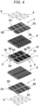
FIG. 4 is an exploded perspective view of a battery block shown inFIG. 3 . -
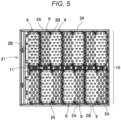
FIG. 5 is a plan view of the battery block of the power supply device shown inFIG. 1 . -
FIG. 6 is a plan view of the battery pack where a sheet heater is disposed in the battery block of the power supply device shown inFIG. 5 . -
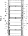
FIG. 7 is an enlarged vertical cross-sectional view of the power supply device along line VII-VII shown inFIG. 1 . -
FIG. 8 is an enlarged cross-sectional view of a main part of the power supply device shown inFIG. 7 . -
FIG. 9 is an exploded perspective view of a conventional power supply device. - Hereinafter, the present invention will be described in detail with reference to the drawings. In the following description, terms indicating specific directions and positions (e.g., "upper", "lower", and other terms including those terms) are used as necessary, but these terms are used to facilitate understanding of the invention with reference to the drawings, and the technical scope of the present invention is not limited by meanings of these terms. Portions denoted by the same reference marks in the plurality of drawings indicate the same or equivalent portions or members.
- Further, the following exemplary embodiment describe specific examples of the technical idea of the present invention, and does not limit the present invention to the following. In addition, unless otherwise specified, dimensions, materials, shapes, relative arrangements, and the like of the components described below are not intended to limit the scope of the present invention, but are intended to be illustrative. In addition, contents described in one exemplary embodiment and example are also applicable to other exemplary embodiments and examples. In addition, sizes, positional relationships, and the like of members shown in the drawings may be exaggerated for clarity of description.
- A power supply device according to a first aspect of the present invention is defined in
claim 1. - In the power supply device described above, each of the battery cells is heated from the one surface on the side of the negative electrode by the sheet heater, so that high safety can be ensured, and reliability as the power supply device can be improved. Since the battery cell is provided with the positive electrode in a metal battery case in an insulated manner, the positive electrode is disposed in an end portion on the side of the positive electrode with an insulator interposed. When a positive electrode lead plate and a negative electrode lead plate are disposed close to each other, and the sheet heater is laminated on surfaces of the positive electrode lead plate and the negative electrode lead plate, moisture absorbed in a conductive portion of the sheet heater or a base sheet of the sheet heater in the power supply device causes a short circuit or electric leakage between the positive electrode and the negative electrode, which causes a decrease in safety. An end portion of the battery cell on the side of the negative electrode is located on a bottom surface of an exterior can and on an end portion opposite to the positive electrode. The sheet heater configured to heat the exterior can from the bottom surface can efficiently conduct heat energy supplied from the lead plate to the whole and quickly heat the whole battery cell. On the side of the positive electrode of the battery cell, the positive electrode is disposed with the insulator interposed. The insulator has extremely low thermal conductivity as compared with metal or the like. For example, as compared with aluminum used for the exterior can, the thermal conductivity of a general insulator is as extremely small as 1/100 or less, and thermal energy supplied to the positive electrode with the lead plate interposed is blocked by the insulator and is not efficiently conducted to the exterior case. Therefore, even when the battery cell is heated from both the side of the positive electrode and the side of the negative electrode, the thermal energy supplied to the side of the positive electrode is blocked by the insulator and is efficiently prevented from being conducted to the whole, and the thermal energy supplied to the side of the negative electrode is extremely efficiently conducted to the whole. The power supply device described above is characterized in that high safety can be ensured while heating the whole battery cell in a state comparable to a device configured to heat a battery cell from both surfaces by heating the battery cell from the one side of the negative electrode.
- In the power supply device according to a second aspect of the present invention, the battery block is divided into a plurality of core modules, each of the core modules includes a plurality of the battery cells, in the core module, the plurality of battery cells are disposed in a parallel posture to one another, a negative electrode surface where the negative electrodes of the plurality of battery cells are disposed in a same plane, and a positive electrode surface where the positive electrodes of the plurality of battery cells are disposed in a same plane are disposed in an opposing surfaces to each other, in the core module, the lead plate is disposed on the negative electrode surface and the positive electrode surface, a negative electrode lead plate on the negative electrode surface is connected to the negative electrodes of the plurality of battery cells, a positive electrode lead plate on the positive electrode surface is connected to the positive electrodes of the plurality of battery cells, and on a side of the negative electrode surface that is one surface of the core module, the sheet heater is thermally coupled to and laminated on a surface of the negative electrode lead plate, and heats the battery cells from the side of the negative electrodes that is one end portions of the battery cells with the negative electrode lead plate interposed.
- In the power supply device described above, while a large number of the battery cells disposed in parallel to each other are heated efficiently and quickly heated by the sheet heater, the overall structure can be simplified and mass production of the battery cells can be efficiently performed.
- In the power supply device according to a third aspect of the present invention, the sheet heater includes: a base sheet made of a nonwoven fabric; a heater wire sewn to the base sheet; and an insulating sheet configured to protect the heater wire, and the insulating sheet is disposed in contact with the lead plate.
- The power supply device described above is characterized in that each of the battery cells can be uniformly heated by the sheet heater while surely insulating the heater wire of the sheet heater.
- The power supply device described above is characterized in that the one sheet heater configured of the heating sheet portions and the joining sheet portion is disposed on the surface of the battery block, and all the battery cells are efficiently and quickly heated from the one surface on the side of the negative electrodes without being heated from the side of the positive electrodes, so that high safety can be ensured.
- In the power supply device according to a fourth aspect of the present invention, each of the heating sheet portions has an elongated shape, and the joining sheet portion is joined to both end portions of the heating sheet portions in a longitudinal direction.
- In the power supply device described above, the heating sheet portions of the sheet heater disposed on the surface of the battery block can be simply and easily disposed at accurate positions, and the side of the negative electrode of each of the battery cells can be efficiently heated with the lead plate interposed.
- In the power supply device according to a fifth aspect of the present invention, the joining sheet portions is disposed with an insulating gap provided between the joining sheet portion and the positive electrode surface.
- In the power supply device described above, the sheet heater can be disposed on the surface of the battery block while surely preventing heating of the side of the positive electrode by the sheet heater.
- In the power supply device according to a sixth aspect of the present invention, the sheet heater includes a heater wire sewn to the joining sheet portion, and the heater wire sewed to the joining sheet portion and the heater wire of the heating sheet portion are a continuous heater wire.
- The power supply device described above is characterized in that it is possible to improve reliability by surely electrically connecting the plurality of heating sheet portions and effectively prevent a failure such as disconnection of the heater wire while inexpensively performing mass production of the sheet heaters in which the plurality of heating sheet portions are joined by the joining sheet portion, and the heating sheet portions and the joining sheet portions have an integrated structure.
- The power supply device according to an seventh aspect of the present invention includes a battery case configured to house the battery block, wherein a cushion sheet is disposed between the battery case and each of the heating sheet portions, and the cushion sheet elastically presses the heating sheet portion against the negative electrode lead plate.
- The power supply device described above is characterized in that the heating sheet portion is surely and stably disposed on the lead plate in a thermally coupled state, and temperature unevenness of all the battery cells can be reduced and uniformly heated by the sheet heater.
- In the power supply device according to a eighth aspect of the present invention, the sheet heaters are disposed on both surfaces of the battery block, the heating sheet portion is laminated on the negative electrode lead plate of each of the core modules, and the heating sheet portions are disposed in opposition to the side of the negative electrodes of all the battery cells.
- The power supply device described above is characterized in that the battery block can be heated from both the surfaces to reduce temperature unevenness of each of the battery cells. In addition, the power supply device described above is characterized in that since the sheet heaters are disposed on both surfaces of the battery block, the battery block configured of a large number of the battery cells can be efficiently heated.
- In the power supply device according to a ninth aspect of the present invention, each of the battery cells is a cylindrical battery. The power supply device described above is characterized in that a cylindrical battery configuring the battery block can be quickly heated while ensuring high safety.
- A power supply device shown in
FIGS. 1 to 3 is configured to be used for, e.g. an electric device, such as a base station, installed outdoors, and is suitable for an application in a use environment of low temperature. The power supply device is therefore used from low to high temperatures, for example, at ambient temperatures ranging from -30°C to 80°C. The power supply device for outdoors is also required to have excellent durability and strength. - In
power supply device 100 shown inFIGS. 1 to 3 ,battery block 10 is accommodated inbattery case 20.Sheet heaters 3 is configured to heatbattery cells 1constituting battery block 10 are disposed insidebattery case 20.Battery block 10 is divided intocore modules 9. Each ofcore modules 9 includes a group ofbattery cells 1. In thiscore module 9, the group ofbattery cells 1 are disposed parallel to one another.Core modules 9 havenegative electrode surface 9B andpositive electrode surfaces 9A. Each of the core modules has a corresponding one ofnegative electrode surfaces 9B and a corresponding one ofpositive electrode surfaces 9A.Negative electrodes 1B of the group ofbattery cells 1 are flush with corresponding one ofnegative electrode surfaces 9B.Positive electrodes 1A of the group ofbattery cells 1 flush with the corresponding one of negativepositive electrode surfaces 9A which is opposite to the corresponding one ofnegative electrode surfaces 9B. Incore module 9, leadplate 2 is disposed on each ofnegative electrode surfaces 9B and each ofpositive electrode surfaces 9A. Negativeelectrode lead plate 2B onnegative electrode surface 9B is connected tonegative electrodes 1B of the group ofbattery cells 1, and positiveelectrode lead plate 2A onpositive electrode surface 9A is connected topositive electrodes 1A of the group ofbattery cells 1, so thatbattery cells 1 are connected in parallel. - In
battery block 10, the plurality ofcore modules 9 are disposed in an array wherenegative electrode surface 9B andpositive electrode surface 9A are alternately located in a same plane. Inbattery block 10, the plurality ofcore modules 9 are disposed,positive electrode surface 9A being disposed betweennegative electrode surfaces 9B,negative electrode surface 9B being disposed betweenpositive electrode surfaces 9A. In each ofcore modules 9, the plurality ofbattery cells 1 are connected bylead plate 2, each ofnegative electrode surface 9B andpositive electrode surface 9A having an elongated shape. Incore modules 9 ofFIG. 4 , the plurality ofbattery cells 1 are disposed in multiple stages and multiple rows, and each ofnegative electrode surface 9B andpositive electrode surface 9A has an elongated shape. Inbattery block 10, the plurality ofcore modules 9 are disposed, elongatednegative electrode surfaces 9B andpositive electrode surfaces 9A being parallel to one another. Incore module 9, negativeelectrode lead plate 2B made of one metal plate is disposed onnegative electrode surface 9B, positive electrode lead plate 2Amade of one metal plate is disposed onpositive electrode surface 9A,negative electrodes 1B ofbattery cells 1 are welded to negativeelectrode lead plate 2B,positive electrodes 1A are welded to positiveelectrode lead plate 2A, and allbattery cells 1 are connected in parallel by negativeelectrode lead plates 2B and positiveelectrode lead plates 2A. - In
battery block 10 including a large number ofcore modules 9,core modules 9 are disposed in multiple stages and multiple rows. Inbattery block 10 shown in the plan view ofFIG. 5 , fourteencore modules 9 are disposed in two columns and seven rows whilespace 11 is provided between the two columns ofcore modules 9. In sevencore modules 9 disposed in each column, positiveelectrode lead plates 2A and negativeelectrode lead plates 2B are connected in series to one another. Incore modules 9 in each column, negativeelectrode lead plates 2B and positiveelectrode lead plates 2A are alternately disposed, and therefore,core modules 9 are connected in series by connectinglead plates 2 adjacent to each other. The two columns ofcore modules 9 may be connected to each other in series or in parallel. - In
core modules 9 disposed in tow, the upper and lower columns shown in the figure,core modules 9 in the upper column andcore modules 9 in the lower column are disposed whilenegative electrode surfaces 9B andpositive electrode surfaces 9A are alternately disposed. That is, each ofnegative electrode surfaces 9B ofcore modules 9 in the upper column are disposed betweennegative electrode surfaces 9B ofcore modules 9 in the lower column, and each ofpositive electrode surfaces 9A ofcore modules 9 in the upper column is disposed betweenpositive electrode surfaces 9A ofcore modules 9 in the lower column. As shown inFIGS. 4 and5 , inbattery block 10 withnegative electrode surfaces 9B ofcore modules 9 disposed alternately,negative electrode surfaces 9B heated by each ofsheet heaters 3 can be uniformly dispersed and disposed on the whole surface ofbattery block 10 to uniformly heatwhole battery cells 1. - As shown in
FIGS. 6 to 8 ,sheet heater 3 includesbase sheet 4 made of nonwoven fabric,heater wire 5 with whichbase sheets 4 is sewn, and insulatingsheet 6 protectingheater wire 5.Base sheet 4 and insulatingsheet 6 are flexible and cushioning nonwoven fabrics with, for example, plastic fibers three-dimensionally assembled without directionality. Heater wires5 is a flexible resistive wire having a surface insulated by an insulating film. A surface of eachbase sheet 4 is sewn with the wire in a predetermined shape.Sheet heater 3 can adjust a partially heating state in accordance with a shape ofheater wire 5 inbase sheet 4. This is becauseheater wire 5 can be sewn in an optimum pattern to increase an amount of heat generation per unit area. Therefore,heater wire 5 inbase sheet 4 such manner thatbattery cells 1 of each ofcore modules 9 may be uniformly heated.Battery block 10 is cooled bybattery case 20, and a temperature of an outer peripheral portion is lower than that of a central portion. Therefore, in the outer peripheral portion ofbattery block 10,sheet heater 3 is sewn in a heater pattern denser than in the central portion to reduce temperature differences among allheated battery cells 1. -
Sheet heater 3 is disposed at a position opposed tobattery cells 1 not on a side ofpositive electrodes 1A, but only on one surface on a side ofnegative electrodes 1B, and is thermally coupled tobattery cells 1 withlead plate 2 interposed to heatbattery cells 1 from the side ofnegative electrodes 1B.Sheet heater 3 configured to heatnegative electrodes 1B without heatingpositive electrodes 1A is placed on the side ofnegative electrode surface 9B of one surface ofcore module 9, and thermally coupled to a surface of negativeelectrode lead plate 2B.Sheet heater 3 heats each ofbattery cells 1 from the side ofnegative electrode 1B, which is one end portion, with negativeelectrode lead plate 2B interposed, and heatsbattery cell 1 from a bottom surface of an exterior can. - In
power supply device 100 shown inFIG. 3 , onesheet heater 3 is disposed on a surface ofbattery block 10 to heat a grouppf battery cells 1 of each ofcore modules 9 from the side ofnegative electrodes 1B. As shown inFIGS. 6 to 8 , insheet heater 3, heating sheet portion 3Ais provided at a position facingnegative electrode surface 9B of each ofcore modules 9, and adjacentheating sheet portions 3A are joined by joiningsheet portions 3B.Sheet heater 3heats battery cells 1 from the side ofnegative electrodes 1B by disposing each ofheating sheet portions 3A facingnegative electrode surface 9B of each ofcore modules 9. Each of joiningsheet portions 3B is disposed at a position facingpositive electrode surface 9A ofcore module 9, and is disposed in a state insulated frompositive electrode surface 9A.Sheet heater 3 has a single sheet shape as a whole by joiningheating sheet portions 3A with joiningsheet portions 3B. - In
sheet heater 3 having a single sheet shape, sinceheating sheet portions 3A and joiningsheet portions 3B have a unified structure, it is not necessary to connect heating sheet portions with lead wires as in a conventional sheet heater. In the sheet heater having the heating sheet portions connected by the lead wires, each of the lead wires is connected to the heater wire of each of heating sheet portions, and the adjacent heating sheet portions are electrically connected via this lead wire. Therefore, there are disadvantages that it takes time and effort to connect the heater wires and the lead wires, so that manufacturing efficiency is deteriorated and manufacturing cost is increased, and that a connection portion between each of the heater wires and each of the lead wires is easily disconnected. In contrast, inintegrated sheet heater 3 havingheating sheet portions 3A and joiningsheet portions 3B of the unified structure, the connection structure between each ofheater wires 5 and each of the lead wires is eliminated,heater wire 5 is sewn to a surface of onebase sheet 4 in a predetermined heater pattern, and then,base sheet 4 is cut to greatly reduce the cost, so that mass production can be efficiently performed. - Further, in
unified sheet heater 3 having each ofheater wires 5 sewn tobase sheet 4 in a predetermined pattern, the heater pattern is more densely arranged to increase the amount of heat generation in the outer portion ofbattery block 10 where heat is easily dissipated. The heater pattern is sparsely arranged to reduce the amount of heat generation in an inside ofbattery block 10 or in a vicinity where a heat generating component is disposed, so that a temperature ofwhole battery block 10 can be made close to uniform. The conventional sheet heater having a plurality of heating sheet portions connected by the lead wires is manufactured by separately manufacturing the plurality of heating sheet portions having different heater patterns and connecting the heating sheet portions having the different heater patterns by the lead wires. Therefore, it is necessary to select specific heating sheet portions having different shapes, to connect the selected heating sheet portions by the lead wires so as to dispose the selected heating sheet portions at specific positions, to define the installation positions of the respective heating sheet portions, and to install the heating sheet portions having the different heater patterns at accurate positions. Therefore, there is a disadvantage that the manufacturing process takes more time and effort. However, sinceintegrated sheet heater 3 is manufactured bysewing heater wires 5 tobase sheets 4 in the specific heater patterns at the specific positions, and then cutting is performed, the heater patterns having different shapes can be arranged at accurate positions without mistakes, and optimal design can be efficiently achieved. - An outer shape of heating sheet portion 3Ais substantially equal to an outer shape of
negative electrode surface 9B ofcore module 9 or an outer shape of negativeelectrode lead plate 2B welded tonegative electrode surface 9B, and all negativeelectrode lead plates 2B are uniformly heated. Incore module 9 ofFIGS. 3 to 5 , sincenegative electrode surface 9B has an elongated shape, the outer shape ofheating sheet portion 3A also has an elongated .shape. In elongatedheating sheet portion 3A, both end portions in a longitudinal direction are joined by joiningsheet portions 3B, andheating sheet portions 3A and joiningsheet portions 3B are configured of onesheet heater 3. Insheet heater 3, both end portions of elongatedheating sheet portions 3A are joined by joiningsheet portions 3B, so that each of heating sheet portions 3Acan be accurately disposed onnegative electrode surface 9B ofcore module 9 without positional deviation when heating sheet portion 3Ais set at a fixed position on the surface ofbattery block 10. In addition, it is possible to efficiently perform mass production ofsheet heater 3 configured of the plurality ofheating sheet portions 3A and the plurality of joiningsheet portions 3B. -
Heating sheet portion 3A is placed on negativeelectrode lead plate 2B to heat negativeelectrode lead plate 2B. Joiningsheet portion 3B is disposed with insulating gap 12 provided between joiningsheet portion 3B andpositive electrode surface 9A, and is disposed to be insulated from positiveelectrode lead plate 2A. Insulating gap 12 insulates joiningsheet portion 3B frompositive electrode surface 9A more reliably byinsulator 13. - Although joining
sheet portions 3B joinheater wires 5 to connectheating sheet portions 3A,heater wires 5 are not necessarily in both joiningsheet portions 3B. This is becausesheet heater 3 connectingheater wires 5 of allheating sheet portions 3A in series to one another heats allheating sheet portions 3A with oneheater wire 5. Since joiningsheet portion 3B thatheater wire 5 is not connected to does not need to be insulated frompositive electrode surface 9A, joiningsheet portion 3B does not necessarily need to provide insulating gap 12 orinsulator 13 between joiningsheet portion 3B andpositive electrode surface 9A. - As shown in
FIG. 7 ,heating sheet portion 3A ofsheet heater 3 is elastically pressed against the surface of negativeelectrode lead plate 2B withcushion sheet 7 interposed to efficiently and uniformly heat negativeelectrode lead plate 2B. Ascushion sheet 7, an elastic sheet of a soft plastic foam such as a soft urethane foam as an insulator is suitable. However, a rubber-like elastic sheet that is elastically deformed by being pressing can also be used.Cushion sheet 7 is a sheet thicker than a distance betweenbattery case 20 and negativeelectrode lead plate 2B in a non-pressing state, and elastically pressesheating sheet portion 3A against negativeelectrode lead plate 2B in a state wherecushion sheet 7 is sandwiched and crushed betweenbattery case 20 and negativeelectrode lead plate 2B. -
Cushion sheet 7 has an outer shape substantially identical to the outer shape ofheating sheet portion 3A, and is placed only on the surface opposed to negativeelectrode lead plate 2B and not on the surface opposed to positiveelectrode lead plate 2A. In this structure, whileheating sheet portion 3A is elastically pressed against negativeelectrode lead plate 2B, gap 14 configured to discharge released gas from a discharge valve (not shown) provided on the side ofpositive electrodes 1A ofbattery cells 1 can be provided betweenbattery case 20 and positiveelectrode lead plate 2A. Further, it is also possible to prevent an adverse effect that moisture absorbed bycushion sheet 7 causes a short circuit on the side ofpositive electrodes 1A ofbattery cells 1. - As shown in
FIGS. 1 and2 ,battery case 20houses battery block 10, and an upper opening portion ofintermediate case 21 is closed byupper surface plate 22 and a lower opening portion is closed bylower surface plate 23.Intermediate case 21,upper surface plate 22, andlower surface plate 23 are made of metal, and are joined by a structure such as screwing, so that an inside has a closed structure. - In
core modules 9 ofbattery block 10,battery cells 1 are disposed in a holder portion provided inplastic battery holder 8, and the plurality ofbattery cells 1 are disposed at fixed positions. Sincebattery holder 8 is manufactured by molding plastic as an insulator, peripheries ofcore modules 9 are insulated bybattery holder 8. The peripheries ofcore modules 9 are insulated bybattery holder 8, but conductive portions are exposed on the surfaces where negativeelectrode lead plate 2B and positiveelectrode lead plate 2A are disposed. - In
battery case 20, insulatingplates 15 such as plastic plates as insulators are disposed on inner surfaces ofupper surface plate 22 andlower surface plate 23. Inpower supply device 100 having this structure, insulatingplates 15 can insulate the inner surface ofupper surface plate 22 and the inner surface oflower surface plate 23 to prevent negativeelectrode lead plates 2B and positiveelectrode lead plates 2A from coming into contact withmetal battery case 20. As shown in a perspective view ofFIG. 2 , insulatingplates 15 closing the upper and lower opening portions ofintermediate case 21 are each provided with elasticbent portions 15A bent into a V-shape on outer peripheral edges. Each of elasticbent portions 15A is inserted into a gap betweenperipheral wall 24 ofintermediate case 21 andbattery block 10 to close the opening portion ofintermediate case 21 without a gap. Inpower supply device 100 with the closed opening portions ofintermediate case 21, the air heated bysheet heaters 3 is prevented from leaking to the outside and circulating, thereby increasing heating efficiency of thebattery cells 1 bysheet heaters 3 and uniformly heating all thebattery cells 1 via the heated internal air. -
Power supply device 100 described above is assembled in the following processes. -
Battery cells 1 are placed at the fixed positions ofplastic battery holder 8. After that, negativeelectrode lead plates 2B are welded tonegative electrodes 1B ofbattery cells 1, and positiveelectrode lead plates 2A are welded topositive electrodes 1A to manufacturebattery block 10. - Since
battery block 10 is divided intocore modules 9, in each ofcore modules 9, negativeelectrode lead plate 2B is welded to the side ofnegative electrodes 1B ofbattery cells 1, and positive electrode lead plate 2Ais welded to the side ofpositive electrodes 1A. Inadjacent core modules 9, negativeelectrode lead plate 2B and positiveelectrode lead plate 2A are alternately disposed, and negativeelectrode lead plates 2B and positiveelectrode lead plates 2A are connected in series bylead plate 2. However,adjacent core modules 9 are connected in parallel by connectinglead plates 2 on the opposite side ofadjacent core modules 9. - Each of
sheet heaters 3 is disposed on respective one of the surfaces ofbattery block 10. Insheet heater 3,heating sheet portions 3A are bonded to negativeelectrode lead plates 2B with a double-sided tape (not shown), and joiningsheet portions 3B are disposed at positions facing positiveelectrode lead plates 2A in an insulated manner. Insheet heater 3, each ofheating sheet portions 3A is bonded to a corresponding one of negativeelectrode lead plates 2B in opposition to each other without being displaced. - Each of
cushion sheets 7 is bonded to the surface of a corresponding one ofheating sheet portions 3A ofsheet heater 3 with a double-sided adhesive tape (not shown).Cushion sheet 7 is bonded to the surface ofheating sheet portion 3A without being displaced. - The lower opening portion of
intermediate case 21 is closed bylower surface plate 23 in a state where insulatingplate 15 is disposed on the inner surface oflower surface plate 23.Lower surface plate 23 is fixed tointermediate case 21 by, for example, screwing.Battery block 10 withsheet heaters 3 and cushionsheets 7 bonded thereto is inserted intointermediate case 21 with the lower opening portion closed bylower surface plate 23, and is disposed at the fixed position. After that, insulatingplates 15 are disposed onbattery block 10, and each of elasticbent portions 15A provided in the outer peripheries of a corresponding one of insulatingplates 15 is inserted betweenperipheral wall 24 ofintermediate case 21 andbattery block 10. - After that,
upper surface plate 22 is fixed tointermediate case 21, and the upper opening portion ofintermediate case 21 is closed byupper surface plate 22.Upper surface plate 23 is fixed tointermediate case 21 by, for example, screwing. - A power supply device according to the present invention includes a sheet heater configured to heat battery cells in a low temperature environment, and is suitably used in an electric device used for an application in a use environment of low temperature, for example, an electric device installed outdoors such as a base station.
-
- 100: power supply device
- 1: battery cell
- 1A: positive electrode
- 1B: negative electrode
- 2: lead plate
- 2A: positive electrode lead plate
- 2B: negative electrode lead plate
- 3: bsheet heater
- 3A: heating sheet portion
- 3B: joining sheet portion
- 4: base sheet
- 5: heater wire
- 6: insulating sheet
- 7: cushion sheet
- 8: battery holder
- 9: core module
- 9A: positive electrode surface
- 9B: negative electrode surface
- 10: battery block
- 11: space
- 12: insulating gap
- 13: insulator
- 14: gap
- 15: insulating plate
- 15A: elastic bent portion
- 20: battery case
- 21: intermediate case
- 22: upper surface plate
- 23: lower surface plate
- 24: peripheral wall
- 90: battery block
- 91: battery cell
- 92: lead plate
- 93: sheet heater
Claims (9)
- A power supply device (100) comprising:a battery block (10) including a plurality of battery cells (1), the plurality of battery cells (1) including positive electrodes (1A) and negative electrodes (1B), each of the plurality of battery cells (1) including a corresponding one of the positive electrodes (1A) and a corresponding one of the negative electrodes (1B) at both ends of the each of the plurality of battery cells (1);lead plates (2) connected to the positive electrode (1A) and the negative electrode (1B) of the plurality of battery cells (1) to electrically connect the battery cells (1) to one another; anda sheet heater (3) configured to heat the battery cells (1), whereinthe sheet heater (3) is placed on a surface of the plurality of battery cells (1) via one of the lead plates (2) on a side of the negative electrode (1B) of the plurality of battery cells (1), the sheet heater (3) being thermally coupled to the surfaces of the plurality of battery cells (1),characterized in that a plurality of core modules are disposed in an array in the battery block (10) such that negative electrode surfaces (9B) and positive electrode surfaces (9A) are alternately disposed while one or more negative electrode surfaces (9B) out of the negative electrode surfaces (9B) are flush with one or more positive electrode surfaces (9A) out of the positive electrode surfaces (9A),the sheet heater (3) includes:a plurality of heating sheet portions (3A) configured to heat the negative electrode surfaces (9B) of the plurality of core modules; anda joining sheet portion (3B) configured to join adjacent ones of the heating sheet portions (3A), andthe joining sheet portion (3B) is disposed opposed to one of the positive electrode surfaces (9A) of the plurality of core modules.
- The power supply device (100) according to claim 1, whereinthe battery block (10) is divided into the plurality of core modules,the plurality of core modules include groups of battery cells (1) out of the plurality of the battery cells (1), each of the plurality of core modules includes a corresponding group of the battery cells (1),the groups of the battery cells (1) of the plurality of core modules are arranged in parallel to one another,the plurality of core modules have the negative electrode surfaces (9B) which negative electrodes (1B) of the groups of the battery cells (1) are flush with,the plurality of core modules have the positive electrode surfaces (9A) which positive electrodes (1A) of the groups of the battery cells (1) are flush with, the positive electrode surfaces (9A) of the plurality of core modules being opposite to the negative electrode surfaces (9B) of the plurality of core modules,the lead plates (2) are disposed on the negative electrode surfaces (9B) and the positive electrode surfaces (9A) of the plurality of core modules,negative electrode lead plates (2B) out of the lead plates (2) which are on the negative electrode surfaces (9B) are connected to the negative electrodes (1B) of the groups of battery cells (1),positive electrode lead plates (2A) out of the lead plates (2) which are on the positive electrode surfaces (9A) are connected to the positive electrodes (1A) of the group of the battery cells (1),the sheet heater (3) is thermally coupled to and placed on surfaces of the negative electrode lead plates (2B) on sides of the negative electrode surfaces (9B) of the plurality of core modules, andthe sheet heater (3) is configured to heat the groups of the battery cells (1) from the negative electrodes (1B) that are one end portions of the groups of the battery cells (1) via the negative electrode lead plates (2B).
- The power supply device (100) according to claim 1 or 2, whereinthe sheet heater (3) includes:a base sheet (4) made of nonwoven fabric;a heater wire (5) with which the base sheet (4) is sewn; andan insulating sheet (6) protecting the heater wire (5), andthe insulating sheet (6) contacts the one of the lead plates (2).
- The power supply device (100) according to any one of claims 1 to 3, whereineach of the heating sheet portions (3A) has an elongated shape, andthe joining sheet portion (3B) is joined to both end portions of the heating sheet portions (3A) in a longitudinal direction.
- The power supply device (100) according to any one of claims 1 to 4, wherein the joining sheet portion (3B) is disposed apart from one of the positive electrode surfaces (9A) via an insulating gap (12) between the joining sheet portion (3B) and the one of the positive electrode surfaces (9A).
- The power supply device (100) according to any one of claims 1 to 5, whereinthe sheet heater (3) includes a heater wire (5) with which the joining sheet portion (3B) is sewn, andthe heater wire (5) with which the joining sheet portion (3B) is sewn and the heater wire (5) of the heating sheet portions (3A) are a continuous heater wire (5).
- The power supply device (100) according to any one of claims 1 to 6, further comprising:a battery case (20) accommodating the battery block (10) therein; anda cushion sheet (7) disposed between the battery case (20) and each of the heating sheet portions (3A), whereinthe cushion sheet (7) elastically presses the heating sheet portions (3A) against the negative electrode lead plates (2B).
- The power supply device (100) according to any one of claims 1 to 7, whereinthe sheet heater (3) comprises sheet heaters disposed on both surfaces of the battery block (10),the heating sheet portions (3A) are placed on the negative electrode lead plates (2B) of the plurality of core modules, andthe heating sheet portions (3A) face the negative electrodes (1B) of all the plurality of battery cells (1).
- The power supply device (100) according to any one of claims 1 to 8, wherein the plurality of battery cells (1) is cylindrical batteries.
Applications Claiming Priority (2)
| Application Number | Priority Date | Filing Date | Title |
|---|---|---|---|
| JP2019064716 | 2019-03-28 | ||
| PCT/JP2020/012308 WO2020196266A1 (en) | 2019-03-28 | 2020-03-19 | Power supply device |
Publications (4)
| Publication Number | Publication Date |
|---|---|
| EP3952008A1 EP3952008A1 (en) | 2022-02-09 |
| EP3952008A4 EP3952008A4 (en) | 2022-06-01 |
| EP3952008B1 true EP3952008B1 (en) | 2023-06-21 |
| EP3952008B8 EP3952008B8 (en) | 2023-07-26 |
Family
ID=72609876
Family Applications (1)
| Application Number | Title | Priority Date | Filing Date |
|---|---|---|---|
| EP20776764.1A Active EP3952008B8 (en) | 2019-03-28 | 2020-03-19 | Power supply device |
Country Status (4)
| Country | Link |
|---|---|
| US (1) | US11916214B2 (en) |
| EP (1) | EP3952008B8 (en) |
| JP (1) | JPWO2020196266A1 (en) |
| WO (1) | WO2020196266A1 (en) |
Families Citing this family (1)
| Publication number | Priority date | Publication date | Assignee | Title |
|---|---|---|---|---|
| EP4016699A1 (en) * | 2020-12-17 | 2022-06-22 | Volvo Car Corporation | Temperature management system |
Family Cites Families (9)
| Publication number | Priority date | Publication date | Assignee | Title |
|---|---|---|---|---|
| JP4925680B2 (en) * | 2006-02-08 | 2012-05-09 | 三洋電機株式会社 | Pack battery |
| EP2530778A1 (en) * | 2010-01-29 | 2012-12-05 | Panasonic Corporation | Cell module |
| EP2365560B1 (en) * | 2010-03-09 | 2012-05-09 | SANYO Electric Co., Ltd. | Battery pack with lead-plates |
| WO2011135762A1 (en) * | 2010-04-28 | 2011-11-03 | パナソニック株式会社 | Battery module |
| EP3220444A1 (en) * | 2016-03-14 | 2017-09-20 | Nordfels GmbH | Battery |
| JP6697332B2 (en) * | 2016-06-28 | 2020-05-20 | 三洋電機株式会社 | Battery system and electric vehicle including battery system |
| JP6460066B2 (en) * | 2016-08-25 | 2019-01-30 | トヨタ自動車株式会社 | Battery pack |
| WO2018165268A1 (en) * | 2017-03-09 | 2018-09-13 | Science Applications International Corporation | Battery assembly |
| DE102018104340A1 (en) * | 2018-02-26 | 2019-08-29 | Metabowerke Gmbh | Battery pack and electric hand tool device and method of manufacture |
-
2020
- 2020-03-19 WO PCT/JP2020/012308 patent/WO2020196266A1/en unknown
- 2020-03-19 US US17/442,043 patent/US11916214B2/en active Active
- 2020-03-19 JP JP2021509311A patent/JPWO2020196266A1/ja active Pending
- 2020-03-19 EP EP20776764.1A patent/EP3952008B8/en active Active
Also Published As
| Publication number | Publication date |
|---|---|
| US11916214B2 (en) | 2024-02-27 |
| JPWO2020196266A1 (en) | 2020-10-01 |
| EP3952008A4 (en) | 2022-06-01 |
| EP3952008A1 (en) | 2022-02-09 |
| US20220190406A1 (en) | 2022-06-16 |
| EP3952008B8 (en) | 2023-07-26 |
| WO2020196266A1 (en) | 2020-10-01 |
Similar Documents
| Publication | Publication Date | Title |
|---|---|---|
| EP3343672B1 (en) | Busbar for cooling battery cell and battery module using same | |
| KR102500561B1 (en) | Battery module and its manufacturing method | |
| US9331313B2 (en) | Battery pack of compact structure | |
| JP6446469B2 (en) | Connector for connecting cellular electrical elements and method for installing such a connector on a battery unit | |
| CN103890997B (en) | Medium-and-large-sized battery assembly | |
| US9917294B2 (en) | Battery cell assembly of novel structure and battery pack employed with the same | |
| EP2500958B1 (en) | Secondary battery | |
| CN113383452B (en) | Battery assembly | |
| CN107565188B (en) | Battery pack | |
| US20220102812A1 (en) | Battery pack | |
| CN112952249B (en) | Battery pack | |
| US20160111760A1 (en) | Power storage module | |
| KR102640328B1 (en) | Large module of battery | |
| US20220285755A1 (en) | Top Cooling Type Battery Pack | |
| EP3952008B1 (en) | Power supply device | |
| JP7325442B2 (en) | battery module | |
| US11670825B2 (en) | Battery pack | |
| KR102272268B1 (en) | Current collector system for battery module, battery module, and vehicle | |
| JP2013545250A (en) | Battery cell | |
| JP7476792B2 (en) | Power storage device | |
| US20220037719A1 (en) | Heated battery module | |
| JP7135363B2 (en) | power storage device | |
| JP2023100002A (en) | Power storage device and power storage facility | |
| CN116706342A (en) | Battery module | |
| CN110858677A (en) | Battery module with heater |
Legal Events
| Date | Code | Title | Description |
|---|---|---|---|
| STAA | Information on the status of an ep patent application or granted ep patent |
Free format text: STATUS: THE INTERNATIONAL PUBLICATION HAS BEEN MADE |
|
| PUAI | Public reference made under article 153(3) epc to a published international application that has entered the european phase |
Free format text: ORIGINAL CODE: 0009012 |
|
| STAA | Information on the status of an ep patent application or granted ep patent |
Free format text: STATUS: REQUEST FOR EXAMINATION WAS MADE |
|
| 17P | Request for examination filed |
Effective date: 20211011 |
|
| AK | Designated contracting states |
Kind code of ref document: A1 Designated state(s): AL AT BE BG CH CY CZ DE DK EE ES FI FR GB GR HR HU IE IS IT LI LT LU LV MC MK MT NL NO PL PT RO RS SE SI SK SM TR |
|
| A4 | Supplementary search report drawn up and despatched |
Effective date: 20220503 |
|
| RIC1 | Information provided on ipc code assigned before grant |
Ipc: H01M 50/512 20210101ALI20220426BHEP Ipc: H01M 50/502 20210101ALI20220426BHEP Ipc: H01M 50/35 20210101ALI20220426BHEP Ipc: H01M 50/224 20210101ALI20220426BHEP Ipc: H01M 50/213 20210101ALI20220426BHEP Ipc: H01M 10/653 20140101ALI20220426BHEP Ipc: H01M 10/6571 20140101ALI20220426BHEP Ipc: H01M 10/6553 20140101ALI20220426BHEP Ipc: H01M 10/643 20140101ALI20220426BHEP Ipc: H01M 10/627 20140101ALI20220426BHEP Ipc: H01M 10/617 20140101ALI20220426BHEP Ipc: H01M 10/615 20140101AFI20220426BHEP |
|
| DAV | Request for validation of the european patent (deleted) | ||
| DAX | Request for extension of the european patent (deleted) | ||
| GRAP | Despatch of communication of intention to grant a patent |
Free format text: ORIGINAL CODE: EPIDOSNIGR1 |
|
| STAA | Information on the status of an ep patent application or granted ep patent |
Free format text: STATUS: GRANT OF PATENT IS INTENDED |
|
| RIC1 | Information provided on ipc code assigned before grant |
Ipc: H01M 50/512 20210101ALI20221215BHEP Ipc: H01M 50/502 20210101ALI20221215BHEP Ipc: H01M 50/35 20210101ALI20221215BHEP Ipc: H01M 50/224 20210101ALI20221215BHEP Ipc: H01M 50/213 20210101ALI20221215BHEP Ipc: H01M 10/653 20140101ALI20221215BHEP Ipc: H01M 10/6571 20140101ALI20221215BHEP Ipc: H01M 10/6553 20140101ALI20221215BHEP Ipc: H01M 10/643 20140101ALI20221215BHEP Ipc: H01M 10/627 20140101ALI20221215BHEP Ipc: H01M 10/617 20140101ALI20221215BHEP Ipc: H01M 10/615 20140101AFI20221215BHEP |
|
| INTG | Intention to grant announced |
Effective date: 20230105 |
|
| GRAS | Grant fee paid |
Free format text: ORIGINAL CODE: EPIDOSNIGR3 |
|
| GRAA | (expected) grant |
Free format text: ORIGINAL CODE: 0009210 |
|
| STAA | Information on the status of an ep patent application or granted ep patent |
Free format text: STATUS: THE PATENT HAS BEEN GRANTED |
|
| RAP3 | Party data changed (applicant data changed or rights of an application transferred) |
Owner name: SANYO ELECTRIC CO., LTD. |
|
| AK | Designated contracting states |
Kind code of ref document: B1 Designated state(s): AL AT BE BG CH CY CZ DE DK EE ES FI FR GB GR HR HU IE IS IT LI LT LU LV MC MK MT NL NO PL PT RO RS SE SI SK SM TR |
|
| REG | Reference to a national code |
Ref country code: DE Ref legal event code: R081 Ref document number: 602020012833 Country of ref document: DE Owner name: PANASONIC ENERGY CO., LTD., MORIGUCHI-SHI, JP Free format text: FORMER OWNER: SANYO ELECTRIC CO., LTD., KADOMA-SHI, OSAKA, JP |
|
| REG | Reference to a national code |
Ref country code: CH Ref legal event code: PK Free format text: BERICHTIGUNG B8 Ref country code: CH Ref legal event code: EP |
|
| REG | Reference to a national code |
Ref country code: DE Ref legal event code: R096 Ref document number: 602020012833 Country of ref document: DE |
|
| REG | Reference to a national code |
Ref country code: AT Ref legal event code: REF Ref document number: 1581565 Country of ref document: AT Kind code of ref document: T Effective date: 20230715 |
|
| RAP2 | Party data changed (patent owner data changed or rights of a patent transferred) |
Owner name: PANASONIC ENERGY CO., LTD. |
|
| REG | Reference to a national code |
Ref country code: IE Ref legal event code: FG4D |
|
| REG | Reference to a national code |
Ref country code: LT Ref legal event code: MG9D |
|
| REG | Reference to a national code |
Ref country code: NL Ref legal event code: MP Effective date: 20230621 |
|
| PG25 | Lapsed in a contracting state [announced via postgrant information from national office to epo] |
Ref country code: SE Free format text: LAPSE BECAUSE OF FAILURE TO SUBMIT A TRANSLATION OF THE DESCRIPTION OR TO PAY THE FEE WITHIN THE PRESCRIBED TIME-LIMIT Effective date: 20230621 Ref country code: NO Free format text: LAPSE BECAUSE OF FAILURE TO SUBMIT A TRANSLATION OF THE DESCRIPTION OR TO PAY THE FEE WITHIN THE PRESCRIBED TIME-LIMIT Effective date: 20230921 |
|
| REG | Reference to a national code |
Ref country code: AT Ref legal event code: MK05 Ref document number: 1581565 Country of ref document: AT Kind code of ref document: T Effective date: 20230621 |
|
| PG25 | Lapsed in a contracting state [announced via postgrant information from national office to epo] |
Ref country code: RS Free format text: LAPSE BECAUSE OF FAILURE TO SUBMIT A TRANSLATION OF THE DESCRIPTION OR TO PAY THE FEE WITHIN THE PRESCRIBED TIME-LIMIT Effective date: 20230621 Ref country code: NL Free format text: LAPSE BECAUSE OF FAILURE TO SUBMIT A TRANSLATION OF THE DESCRIPTION OR TO PAY THE FEE WITHIN THE PRESCRIBED TIME-LIMIT Effective date: 20230621 Ref country code: LV Free format text: LAPSE BECAUSE OF FAILURE TO SUBMIT A TRANSLATION OF THE DESCRIPTION OR TO PAY THE FEE WITHIN THE PRESCRIBED TIME-LIMIT Effective date: 20230621 Ref country code: LT Free format text: LAPSE BECAUSE OF FAILURE TO SUBMIT A TRANSLATION OF THE DESCRIPTION OR TO PAY THE FEE WITHIN THE PRESCRIBED TIME-LIMIT Effective date: 20230621 Ref country code: HR Free format text: LAPSE BECAUSE OF FAILURE TO SUBMIT A TRANSLATION OF THE DESCRIPTION OR TO PAY THE FEE WITHIN THE PRESCRIBED TIME-LIMIT Effective date: 20230621 Ref country code: GR Free format text: LAPSE BECAUSE OF FAILURE TO SUBMIT A TRANSLATION OF THE DESCRIPTION OR TO PAY THE FEE WITHIN THE PRESCRIBED TIME-LIMIT Effective date: 20230922 |
|
| PG25 | Lapsed in a contracting state [announced via postgrant information from national office to epo] |
Ref country code: FI Free format text: LAPSE BECAUSE OF FAILURE TO SUBMIT A TRANSLATION OF THE DESCRIPTION OR TO PAY THE FEE WITHIN THE PRESCRIBED TIME-LIMIT Effective date: 20230621 |
|
| PG25 | Lapsed in a contracting state [announced via postgrant information from national office to epo] |
Ref country code: SK Free format text: LAPSE BECAUSE OF FAILURE TO SUBMIT A TRANSLATION OF THE DESCRIPTION OR TO PAY THE FEE WITHIN THE PRESCRIBED TIME-LIMIT Effective date: 20230621 |
|
| PG25 | Lapsed in a contracting state [announced via postgrant information from national office to epo] |
Ref country code: ES Free format text: LAPSE BECAUSE OF FAILURE TO SUBMIT A TRANSLATION OF THE DESCRIPTION OR TO PAY THE FEE WITHIN THE PRESCRIBED TIME-LIMIT Effective date: 20230621 |
|
| PG25 | Lapsed in a contracting state [announced via postgrant information from national office to epo] |
Ref country code: IS Free format text: LAPSE BECAUSE OF FAILURE TO SUBMIT A TRANSLATION OF THE DESCRIPTION OR TO PAY THE FEE WITHIN THE PRESCRIBED TIME-LIMIT Effective date: 20231021 |
|
| PG25 | Lapsed in a contracting state [announced via postgrant information from national office to epo] |
Ref country code: SM Free format text: LAPSE BECAUSE OF FAILURE TO SUBMIT A TRANSLATION OF THE DESCRIPTION OR TO PAY THE FEE WITHIN THE PRESCRIBED TIME-LIMIT Effective date: 20230621 Ref country code: SK Free format text: LAPSE BECAUSE OF FAILURE TO SUBMIT A TRANSLATION OF THE DESCRIPTION OR TO PAY THE FEE WITHIN THE PRESCRIBED TIME-LIMIT Effective date: 20230621 Ref country code: RO Free format text: LAPSE BECAUSE OF FAILURE TO SUBMIT A TRANSLATION OF THE DESCRIPTION OR TO PAY THE FEE WITHIN THE PRESCRIBED TIME-LIMIT Effective date: 20230621 Ref country code: PT Free format text: LAPSE BECAUSE OF FAILURE TO SUBMIT A TRANSLATION OF THE DESCRIPTION OR TO PAY THE FEE WITHIN THE PRESCRIBED TIME-LIMIT Effective date: 20231023 Ref country code: IS Free format text: LAPSE BECAUSE OF FAILURE TO SUBMIT A TRANSLATION OF THE DESCRIPTION OR TO PAY THE FEE WITHIN THE PRESCRIBED TIME-LIMIT Effective date: 20231021 Ref country code: ES Free format text: LAPSE BECAUSE OF FAILURE TO SUBMIT A TRANSLATION OF THE DESCRIPTION OR TO PAY THE FEE WITHIN THE PRESCRIBED TIME-LIMIT Effective date: 20230621 Ref country code: EE Free format text: LAPSE BECAUSE OF FAILURE TO SUBMIT A TRANSLATION OF THE DESCRIPTION OR TO PAY THE FEE WITHIN THE PRESCRIBED TIME-LIMIT Effective date: 20230621 Ref country code: CZ Free format text: LAPSE BECAUSE OF FAILURE TO SUBMIT A TRANSLATION OF THE DESCRIPTION OR TO PAY THE FEE WITHIN THE PRESCRIBED TIME-LIMIT Effective date: 20230621 Ref country code: AT Free format text: LAPSE BECAUSE OF FAILURE TO SUBMIT A TRANSLATION OF THE DESCRIPTION OR TO PAY THE FEE WITHIN THE PRESCRIBED TIME-LIMIT Effective date: 20230621 |
|
| PG25 | Lapsed in a contracting state [announced via postgrant information from national office to epo] |
Ref country code: PL Free format text: LAPSE BECAUSE OF FAILURE TO SUBMIT A TRANSLATION OF THE DESCRIPTION OR TO PAY THE FEE WITHIN THE PRESCRIBED TIME-LIMIT Effective date: 20230621 |