EP2365560B1 - Battery pack with lead-plates - Google Patents
Battery pack with lead-plates Download PDFInfo
- Publication number
- EP2365560B1 EP2365560B1 EP20100002451 EP10002451A EP2365560B1 EP 2365560 B1 EP2365560 B1 EP 2365560B1 EP 20100002451 EP20100002451 EP 20100002451 EP 10002451 A EP10002451 A EP 10002451A EP 2365560 B1 EP2365560 B1 EP 2365560B1
- Authority
- EP
- European Patent Office
- Prior art keywords
- lead
- plates
- battery
- heat radiating
- external case
- Prior art date
- Legal status (The legal status is an assumption and is not a legal conclusion. Google has not performed a legal analysis and makes no representation as to the accuracy of the status listed.)
- Active
Links
- 239000004033 plastic Substances 0.000 claims abstract description 7
- 229920003023 plastic Polymers 0.000 claims abstract description 7
- 229910052751 metal Inorganic materials 0.000 claims description 8
- 239000002184 metal Substances 0.000 claims description 8
- 238000010276 construction Methods 0.000 claims description 5
- 238000003780 insertion Methods 0.000 claims description 4
- 230000037431 insertion Effects 0.000 claims description 4
- 238000003491 array Methods 0.000 claims description 2
- 229920002050 silicone resin Polymers 0.000 claims description 2
- 230000014759 maintenance of location Effects 0.000 claims 1
- 230000005855 radiation Effects 0.000 description 11
- 238000003466 welding Methods 0.000 description 7
- HBBGRARXTFLTSG-UHFFFAOYSA-N Lithium ion Chemical compound [Li+] HBBGRARXTFLTSG-UHFFFAOYSA-N 0.000 description 6
- 229910001416 lithium ion Inorganic materials 0.000 description 6
- PXHVJJICTQNCMI-UHFFFAOYSA-N Nickel Chemical compound [Ni] PXHVJJICTQNCMI-UHFFFAOYSA-N 0.000 description 5
- 238000007599 discharging Methods 0.000 description 4
- 238000000034 method Methods 0.000 description 4
- 230000004888 barrier function Effects 0.000 description 3
- WABPQHHGFIMREM-UHFFFAOYSA-N lead(0) Chemical compound [Pb] WABPQHHGFIMREM-UHFFFAOYSA-N 0.000 description 3
- XEEYBQQBJWHFJM-UHFFFAOYSA-N Iron Chemical compound [Fe] XEEYBQQBJWHFJM-UHFFFAOYSA-N 0.000 description 2
- 229920000122 acrylonitrile butadiene styrene Polymers 0.000 description 2
- 238000001514 detection method Methods 0.000 description 2
- 239000003792 electrolyte Substances 0.000 description 2
- 238000010438 heat treatment Methods 0.000 description 2
- 239000000463 material Substances 0.000 description 2
- 229910052759 nickel Inorganic materials 0.000 description 2
- 238000003825 pressing Methods 0.000 description 2
- 239000000725 suspension Substances 0.000 description 2
- RYGMFSIKBFXOCR-UHFFFAOYSA-N Copper Chemical compound [Cu] RYGMFSIKBFXOCR-UHFFFAOYSA-N 0.000 description 1
- 229910000881 Cu alloy Inorganic materials 0.000 description 1
- 229910000831 Steel Inorganic materials 0.000 description 1
- 230000002159 abnormal effect Effects 0.000 description 1
- 239000004676 acrylonitrile butadiene styrene Substances 0.000 description 1
- OJIJEKBXJYRIBZ-UHFFFAOYSA-N cadmium nickel Chemical compound [Ni].[Cd] OJIJEKBXJYRIBZ-UHFFFAOYSA-N 0.000 description 1
- 238000001816 cooling Methods 0.000 description 1
- 229910052802 copper Inorganic materials 0.000 description 1
- 239000010949 copper Substances 0.000 description 1
- 230000001627 detrimental effect Effects 0.000 description 1
- 230000002349 favourable effect Effects 0.000 description 1
- 239000011810 insulating material Substances 0.000 description 1
- 229910052742 iron Inorganic materials 0.000 description 1
- 239000002991 molded plastic Substances 0.000 description 1
- 229910000652 nickel hydride Inorganic materials 0.000 description 1
- 239000000088 plastic resin Substances 0.000 description 1
- 239000004417 polycarbonate Substances 0.000 description 1
- 229920000515 polycarbonate Polymers 0.000 description 1
- 239000010959 steel Substances 0.000 description 1
Images


Classifications
-
- H—ELECTRICITY
- H01—ELECTRIC ELEMENTS
- H01M—PROCESSES OR MEANS, e.g. BATTERIES, FOR THE DIRECT CONVERSION OF CHEMICAL ENERGY INTO ELECTRICAL ENERGY
- H01M10/00—Secondary cells; Manufacture thereof
- H01M10/60—Heating or cooling; Temperature control
- H01M10/65—Means for temperature control structurally associated with the cells
- H01M10/655—Solid structures for heat exchange or heat conduction
- H01M10/6554—Rods or plates
-
- H—ELECTRICITY
- H01—ELECTRIC ELEMENTS
- H01M—PROCESSES OR MEANS, e.g. BATTERIES, FOR THE DIRECT CONVERSION OF CHEMICAL ENERGY INTO ELECTRICAL ENERGY
- H01M50/00—Constructional details or processes of manufacture of the non-active parts of electrochemical cells other than fuel cells, e.g. hybrid cells
- H01M50/20—Mountings; Secondary casings or frames; Racks, modules or packs; Suspension devices; Shock absorbers; Transport or carrying devices; Holders
- H01M50/218—Mountings; Secondary casings or frames; Racks, modules or packs; Suspension devices; Shock absorbers; Transport or carrying devices; Holders characterised by the material
- H01M50/22—Mountings; Secondary casings or frames; Racks, modules or packs; Suspension devices; Shock absorbers; Transport or carrying devices; Holders characterised by the material of the casings or racks
- H01M50/227—Organic material
-
- H—ELECTRICITY
- H01—ELECTRIC ELEMENTS
- H01M—PROCESSES OR MEANS, e.g. BATTERIES, FOR THE DIRECT CONVERSION OF CHEMICAL ENERGY INTO ELECTRICAL ENERGY
- H01M10/00—Secondary cells; Manufacture thereof
- H01M10/60—Heating or cooling; Temperature control
- H01M10/61—Types of temperature control
- H01M10/613—Cooling or keeping cold
-
- H—ELECTRICITY
- H01—ELECTRIC ELEMENTS
- H01M—PROCESSES OR MEANS, e.g. BATTERIES, FOR THE DIRECT CONVERSION OF CHEMICAL ENERGY INTO ELECTRICAL ENERGY
- H01M50/00—Constructional details or processes of manufacture of the non-active parts of electrochemical cells other than fuel cells, e.g. hybrid cells
- H01M50/20—Mountings; Secondary casings or frames; Racks, modules or packs; Suspension devices; Shock absorbers; Transport or carrying devices; Holders
- H01M50/204—Racks, modules or packs for multiple batteries or multiple cells
- H01M50/207—Racks, modules or packs for multiple batteries or multiple cells characterised by their shape
- H01M50/213—Racks, modules or packs for multiple batteries or multiple cells characterised by their shape adapted for cells having curved cross-section, e.g. round or elliptic
-
- H—ELECTRICITY
- H01—ELECTRIC ELEMENTS
- H01M—PROCESSES OR MEANS, e.g. BATTERIES, FOR THE DIRECT CONVERSION OF CHEMICAL ENERGY INTO ELECTRICAL ENERGY
- H01M50/00—Constructional details or processes of manufacture of the non-active parts of electrochemical cells other than fuel cells, e.g. hybrid cells
- H01M50/20—Mountings; Secondary casings or frames; Racks, modules or packs; Suspension devices; Shock absorbers; Transport or carrying devices; Holders
- H01M50/289—Mountings; Secondary casings or frames; Racks, modules or packs; Suspension devices; Shock absorbers; Transport or carrying devices; Holders characterised by spacing elements or positioning means within frames, racks or packs
- H01M50/291—Mountings; Secondary casings or frames; Racks, modules or packs; Suspension devices; Shock absorbers; Transport or carrying devices; Holders characterised by spacing elements or positioning means within frames, racks or packs characterised by their shape
-
- H—ELECTRICITY
- H01—ELECTRIC ELEMENTS
- H01M—PROCESSES OR MEANS, e.g. BATTERIES, FOR THE DIRECT CONVERSION OF CHEMICAL ENERGY INTO ELECTRICAL ENERGY
- H01M50/00—Constructional details or processes of manufacture of the non-active parts of electrochemical cells other than fuel cells, e.g. hybrid cells
- H01M50/50—Current conducting connections for cells or batteries
- H01M50/502—Interconnectors for connecting terminals of adjacent batteries; Interconnectors for connecting cells outside a battery casing
- H01M50/503—Interconnectors for connecting terminals of adjacent batteries; Interconnectors for connecting cells outside a battery casing characterised by the shape of the interconnectors
-
- H—ELECTRICITY
- H01—ELECTRIC ELEMENTS
- H01M—PROCESSES OR MEANS, e.g. BATTERIES, FOR THE DIRECT CONVERSION OF CHEMICAL ENERGY INTO ELECTRICAL ENERGY
- H01M50/00—Constructional details or processes of manufacture of the non-active parts of electrochemical cells other than fuel cells, e.g. hybrid cells
- H01M50/50—Current conducting connections for cells or batteries
- H01M50/502—Interconnectors for connecting terminals of adjacent batteries; Interconnectors for connecting cells outside a battery casing
- H01M50/514—Methods for interconnecting adjacent batteries or cells
- H01M50/516—Methods for interconnecting adjacent batteries or cells by welding, soldering or brazing
-
- H—ELECTRICITY
- H01—ELECTRIC ELEMENTS
- H01M—PROCESSES OR MEANS, e.g. BATTERIES, FOR THE DIRECT CONVERSION OF CHEMICAL ENERGY INTO ELECTRICAL ENERGY
- H01M50/00—Constructional details or processes of manufacture of the non-active parts of electrochemical cells other than fuel cells, e.g. hybrid cells
- H01M50/50—Current conducting connections for cells or batteries
- H01M50/502—Interconnectors for connecting terminals of adjacent batteries; Interconnectors for connecting cells outside a battery casing
- H01M50/521—Interconnectors for connecting terminals of adjacent batteries; Interconnectors for connecting cells outside a battery casing characterised by the material
- H01M50/522—Inorganic material
-
- H—ELECTRICITY
- H01—ELECTRIC ELEMENTS
- H01M—PROCESSES OR MEANS, e.g. BATTERIES, FOR THE DIRECT CONVERSION OF CHEMICAL ENERGY INTO ELECTRICAL ENERGY
- H01M10/00—Secondary cells; Manufacture thereof
- H01M10/60—Heating or cooling; Temperature control
- H01M10/64—Heating or cooling; Temperature control characterised by the shape of the cells
- H01M10/643—Cylindrical cells
-
- H—ELECTRICITY
- H01—ELECTRIC ELEMENTS
- H01M—PROCESSES OR MEANS, e.g. BATTERIES, FOR THE DIRECT CONVERSION OF CHEMICAL ENERGY INTO ELECTRICAL ENERGY
- H01M10/00—Secondary cells; Manufacture thereof
- H01M10/60—Heating or cooling; Temperature control
- H01M10/65—Means for temperature control structurally associated with the cells
- H01M10/655—Solid structures for heat exchange or heat conduction
- H01M10/6553—Terminals or leads
-
- Y—GENERAL TAGGING OF NEW TECHNOLOGICAL DEVELOPMENTS; GENERAL TAGGING OF CROSS-SECTIONAL TECHNOLOGIES SPANNING OVER SEVERAL SECTIONS OF THE IPC; TECHNICAL SUBJECTS COVERED BY FORMER USPC CROSS-REFERENCE ART COLLECTIONS [XRACs] AND DIGESTS
- Y02—TECHNOLOGIES OR APPLICATIONS FOR MITIGATION OR ADAPTATION AGAINST CLIMATE CHANGE
- Y02E—REDUCTION OF GREENHOUSE GAS [GHG] EMISSIONS, RELATED TO ENERGY GENERATION, TRANSMISSION OR DISTRIBUTION
- Y02E60/00—Enabling technologies; Technologies with a potential or indirect contribution to GHG emissions mitigation
- Y02E60/10—Energy storage using batteries
Definitions
- the present invention relates to a battery pack with lead-plates weld-attached to electrodes at the ends of a plurality rechargeable batteries.
- the present invention relates to a battery pack in which heat is radiated from each battery via the lead-plates.
- lead projections are established on the lead-plates, and heat is radiated from the batteries through the lead-plates by radiating lead-plate heat from the lead projections. Since heat is radiated from the lead projections of a battery pack with this structure, it is difficult to increase the heat radiating area. Furthermore, since the lead projections connect with battery electrodes and are charged to those voltages, they cannot protrude outside the external case to radiate heat.
- the external case houses a plurality of circular cylindrical rechargeable batteries and is provided with a heat radiating section.
- Heat collectors are disposed next to batteries housed in the central region of the external case, and heat-pipes transfer heat from the heat collectors to the external case heat radiating section for radiation.
- battery heat is transferred to the heat collectors, and heat collector heat is transferred by the heat-pipes to the external case heat radiating section for radiation to the outside.
- JP 2009-176689 discloses a battery pack, in which short circuit of a lead-plate with a radiating plate is certainly prevented, and respective batteries have efficient radiation of heat through the lead plate and the radiating plate by making a thermal conduction from the lead-plate to the radiating plate.
- the present invention was developed with the object of correcting these drawbacks.
- the battery pack of the present invention is provided with a plurality of batteries 1 that can be charged, lead-plates 3 that connect to the electrodes 1A at the ends of the batteries 1, and an external case 2 that houses a battery assembly 9 of batteries 1 connected by lead-plates 3.
- the external case 2 has a heat radiating section 10 on at least one of its opposing surfaces to radiate battery 1 heat.
- Batteries 1 are arranged in parallel orientation and housed in the external case 2 with their electrodes 1A opposite the heat radiating section 10 inside surfaces.
- the battery assembly 9 is housed in the external case 2 with the lead-plates 3, which are connected to electrodes 1A at the ends of the batteries 1, disposed at heat radiating section 10 inside surfaces.
- the lead-plates 3 are thermally connected to the inside surfaces of the heat radiating sections 10.
- the external case 2 is made of plastic and is provided with inward protruding regions 12 that protrude from the heat radiating section 10 inside surfaces to make contact and thermal connection with the surfaces of the lead-plates 3.
- the heat radiating sections 10 have depressions 13 established on the outside opposite the inward protruding regions 12. In this battery pack, battery 1 heat is transferred from the lead-plates 3 to heat radiating section 10 inward protruding regions 12 to radiate heat from the external case 2 to the outside.
- the battery pack described above has the characteristic that heat from each battery can be effectively radiated from the external case to the outside with a simple heat radiating structure. This is because the lead-plates connected to the electrodes of each battery are thermally joined to the inward protruding regions that stand-off from the inside surfaces of the external case heat radiating sections. Further, by providing inward protruding regions, depressions can be established in the external case. Battery heat is transferred from the lead-plates to heat radiating section inward protruding regions, and radiated to the outside from the external case. In this structure, the lead-plates can be put in tight thermal contact over large areas with the inward protruding regions to efficiently radiate lead-plate heat to the outside.
- the battery pack described above connects lead-plates to electrodes at both ends of all the batteries, and lead-plate heat is radiated to the outside from the external case heat radiating section.
- This heat radiating configuration makes it possible to uniformly cool all the batteries, and has the characteristic that the temperature differences between individual batteries can be reduced to enable uniform cooling.
- heat radiating sections 10 can be provided on both opposing sides of the external case 2.
- heat from the lead-plates connected to both ends of the batteries is transferred to the inward protruding regions of heat radiating sections on both sides of the external case to allow battery heat to be radiated to the outside in and extremely efficient manner.
- heat radiating fins 14 can be provided in single-piece construction with the depressions 13 of the heat radiating sections 10.
- the heat radiating fins reinforce the inward protruding regions and prevent mechanical deformation.
- the heat radiating fins which are established on outside surfaces opposite the inward protruding regions, increase the heat radiating area for efficient heat radiation. Inward protruding regions that do not mechanically deform can reliably make tight contact with the lead-plates to maintain ideal thermal connection and improve heat transfer from the lead-plates for efficient heat radiation.
- the heat radiating fins on the outside surface reinforce the inward protruding regions and prevent their deformation. Consequently, even when the batteries become hot, the inward protruding regions remain in tight thermal contact with the lead-plates over a wide area and lead-plate heat is efficiently radiated to the outside.
- the battery pack of the present invention can be provided with an inner case 4 to hold the batteries 1 in fixed positions.
- the inner case 4 can be provided with battery loading sections 22 that are open at both ends and dispose the inserted batteries 1 in fixed positions.
- the inner case 4 can be provided with recessed regions 21 that align the lead-plates 3 in specified positions connected to the electrodes 1A at the ends of the batteries 1 loaded in the battery loading sections 22.
- the outlines of the inward protruding regions 12 established on the inside surfaces of the external case 2 heat radiating sections 10 can be made to fit into the recessed regions 21 and dispose the inward protruding regions 12 in specified locations. This allows the inward protruding regions 12 to align inside the recessed regions 21 and thermally connect with the lead-plates 3.
- the inward protruding regions established on the external case can reliably make thermal connection with the lead-plates without shifting position to enable efficient battery heat radiation. This is because the lead-plates and inward protruding regions can be disposed in fixed positions by the inner case.
- the inner case 4 can be provided with a plurality of columns of recessed regions 21 to dispose a plurality of lead-plates 3 in fixed positions and parallel orientation. Further, a plurality of inward protruding regions 12 can be provided in the external case 2 heat radiating sections 10 for insertion into each recessed region 21. In the battery pack described above, batteries can be efficiently cooled via each lead-plate while reliably preventing short circuits between adjacent lead-plates.
- flexible heat transfer sheet 7 can be inserted between the inward protruding regions 12 established on the external case 2 and the lead-plates 3.
- the lead-plates can transfer heat more efficiently to the inward protruding regions for more efficient heat radiation.
- lead-plates 3 can be sheet-metal that can deform flexibly, and flexible pressure tabs 33 can be provided to resiliently press against the electrodes 1A on the ends of the batteries 1.
- the flexible pressure tabs 33 can project in a flexible manner towards the battery 1 electrodes 1A, and the flexible pressure tabs 33 can press against the battery 1 electrodes 1A for electrical connection.
- the lead-plates can make reliable electrical connection to the battery electrodes without joining the lead-plates to the electrodes by a technique such as spot-welding.
- the lead-plates can be put in tight contact under more favorable conditions with the protruding surfaces of the inward protruding regions to establish thermal connection in an ideal manner.
- the flexible pressure tabs on the lead-plates not only press resiliently against the battery electrodes for electrical connection, but also resiliently press the lead-plates into tight contact with the protruding surfaces of the inward protruding regions as a result of the reaction force of the flexible pressure tabs pressing against the battery electrodes.
- the battery pack of Figs. 1-6 has a battery assembly 9 housed in an external case 2.
- the battery assembly 9 has a plurality of batteries 1 that can be charged connected in series and parallel by lead-plates 3. [external case]
- the external case shown in Figs. 2 , 3 , and 6 houses a battery assembly 9 and has a box-shape with heat radiating sections 10 on opposing surfaces to radiate heat away from the batteries 1.
- the external case 2 of the figures has heat radiating sections 10 provided on both opposing side-walls, the external case can also have a heat radiating section on only one of its opposing side-walls.
- the external case 2 of the figures has rectangular heat radiating sections 10, and perimeter walls 11 connected around those rectangular heat radiating sections 10.
- Each battery 1 is loaded in the battery assembly 9 with an orientation that is perpendicular to the external case 2 heat radiating sections 10, and all the electrodes 1A of the batteries 1 are disposed opposite the inside surface of a heat radiating section 10.
- the external case 2 is made of molded plastic.
- the external case 2 is provided with inward protruding regions 12 on the inside surfaces of the heat radiating sections 10 to make surface-to-surface contact and thermal connection with the lead-plates 3 disposed inside.
- the protruding surfaces of the inward protruding regions 12 are thermally joined to the surfaces of the lead-plates 3.
- the protruding surfaces of the inward protruding regions 12 tightly contact the surfaces of the lead-plates 3 directly.
- the protruding surfaces of the inward protruding regions 12 tightly contact the lead-plates 3 through flexible heat transfer sheet 7.
- depressions 13 can be established in the outside surfaces of the inward protruding regions 12, and heat radiating fins 14 are molded in single-piece construction with the depressions 13.
- the battery assembly 9 of Figs. 2-4 has a plurality of lead-plates 3 disposed in a separated manner on both sides of the battery assembly 9.
- the external case 2 has a plurality of inward protruding regions 12 established to make thermal connection with the surface of each lead-plate 3.
- the battery assembly 9 of the figures has batteries 1 arranged in fixed positions in a plastic inner case 4.
- the inner case 4 is provided with a plurality of columns of recessed regions 21 to dispose the plurality of lead-plates 3 in fixed positions and parallel orientation.
- the external case 2 is provided with a plurality of inward protruding regions 12 in the heat radiating sections 10 that insert into each recessed region 21.
- the outlines of the inward protruding regions 12 are shaped to fit in the recessed regions 21 and hold the battery assembly 9 in a fixed position inside the external case 2.
- the outlines of the inward protruding regions 12 are made slightly smaller than the size of the interiors of the recessed regions 21, and the inward protruding regions 12 insert into the recessed regions 21 in a manner that prevents position shift.
- heat radiating fins 14 are established with the depressions 13 in a manner that does not project out from the heat radiating sections 10.
- the heat radiating fins 14 of the figures are rows of projections disposed in an intersecting manner. These heat radiating fins 14 can reinforce the heat radiating sections 10 while increasing the area for heat radiation.
- heat radiating fins 14 that are arrays of rows of intersecting projections reinforce the inward protruding regions 12 and prevent vertical and horizontal deformation of those inward protruding regions 12. This allows the protruding surfaces of the inward protruding regions 12 to stably press against the surfaces of the lead-plates 3 for thermal connection.
- a configuration of heat radiating fins 14 established with depressions 13 in a manner that does not project from the surfaces of the external case 2 does not increase the size of the external case 2 with projecting fins, and can prevent damage to the heat radiating fins 14 caused by projection from the surface.
- the heat radiating fins can also be made taller to project from the surfaces of the external case to increase the heat radiating area and improve the heat radiating efficiency.
- the heat radiating fins 14 described above are established with the depressions 13, the heat radiating fins can also be local protrusions in depressions or hill-and-valley shapes within depressions.
- the external case 2 is molded from plastic resin such as acrylonitrile-butadiene-styrene (ABS) resin.
- ABS acrylonitrile-butadiene-styrene
- the external case 2 is divided into two parts at the middle of the perimeter walls 11, and is connected together by a fastening method such as screw-fastening or snap-fit connection.
- the external case 2 can be designed in various sizes and shapes depending on the battery pack application, purpose, operating conditions, and the size, shape, and number of batteries employed.
- the external case 2 shown in Figs. 1-3 is divided into a first external case 2A and a second external case 2B.
- the external case 2 of the figures is provided with attachment extensions 15 on its perimeter surfaces to connect the first external case 2A and the second external case 2B.
- the first external case 2A and the second external case 2B are joined together by connecting corresponding attachment extensions 15 together.
- the external case 2 is fastened together by screw-fastening.
- the first external case 2A and the second external case 2B are approximately symmetrical.
- the battery pack is used with the external case 2 in the standing orientation shown in the figures, namely with one of the perimeter walls 11 at the bottom.
- the external case 2 can also be used with one of the heat radiating section 10 surfaces, which is provided with heat radiating fins 14, at the bottom.
- the bottom surface of the external case 2 can be selected depending on battery pack operating conditions.
- Figs. 2-5 show the battery assembly 9.
- the battery assembly 9 of those figures is provided with batteries 1 that can be charged and are disposed next to each other in parallel orientation, an inner case 4 that disposes the batteries 1 in fixed positions, and a plurality of lead-plates 3 weld-attached to electrodes 1A at the ends of each battery 1 disposed in the inner case 4 to electrically connect adjacent batteries 1.
- the batteries 1 of the figures are circular cylindrical batteries.
- a plurality of batteries 1 are arranged in multiple rows and columns with the electrodes 1A at each end of the batteries 1 positioned in common planes.
- the battery assembly 9 of the figures is an array of batteries 1 with six horizontal rows and fourteen vertical columns. Batteries 1 in adjacent columns are shifted vertically to position batteries 1 in one column midway between batteries 1 in an adjacent column. This allows circular cylindrical batteries 1 to be arrayed in multiple columns in close proximity.
- the battery pack of the present invention is not limited to a configuration having the number and arrangement of batteries described above.
- batteries can also be disposed in a rectangular grid arrangement (no column shifting).
- the batteries 1 are batteries that can be charged. Circular cylindrical batteries are used as the batteries 1 in the battery pack of the figures, although rectangular batteries and thin-outline batteries can also be used. In the present embodiment, circular cylindrical lithium ion batteries are used as the batteries 1. Lithium ion batteries are suitable for use in a high capacity, high output battery pack. This is because lithium ion batteries can achieve high capacity-to-weight and capacity-to-volume ratios. However, the battery pack of the present invention is not limited to the use of lithium ion batteries, and rechargeable batteries such as nickel-hydride batteries and nickel-cadmium batteries can also be used.
- the battery assembly 9 shown in Fig. 5 has batteries 1 inserted in specified positions in inner case 4 battery loading sections 22.
- the inner case 4 is formed in a shape that has circular cylindrical battery loading sections 22.
- the battery loading sections 22 are formed with interior shapes that can accept circular cylindrical battery insertion.
- the inner case 4 of the figures is provided with eighty-four battery loading sections 22 to insert batteries 1 in six rows and fourteen columns. Both ends of the battery loading sections 22 are open.
- the battery pack of Fig. 5 has an inner case 4 that is divided into two pieces in the lengthwise direction of the cylindrical batteries 1 (left and right in the figure). The left and right inner case 4 pieces are formed with both ends of the battery loading sections 22 open to accept circular cylindrical batteries 1.
- the inner case 4 is molded with an insulating material such as plastic.
- An inner case 4 molded from plastic in a shape establishing battery loading sections 22 can dispose the plurality of batteries 1 in an array of separate compartments that accurately align those batteries 1 in specified positions. Further, by separating the batteries 1 in independent compartments, conditions that induce battery 1 thermal runaway can be prevented.
- the connected inner case 4, which is molded as two pieces, exposes the electrodes 1A at the ends of the batteries 1 to the outside from the open ends of the battery loading sections 22.
- the lead-plates 3 are weld-attached to the exposed electrodes 1A by a technique such as spot-welding or laser-welding.
- Polycarbonate can be used as the inner case 4 plastic material. This material has high strength and is not easily dissolved by lithium ion battery electrolyte that could leak from a battery. Conversely, ABS resin is easily dissolved by lithium ion battery electrolyte and its use is undesirable.
- the inner case 4 is provided with recessed regions 21 formed to hold lead-plates 3 in fixed positions at both open ends of the battery loading sections 22.
- the lead-plates 3 are inserted into the recessed regions 21 and connected to the electrodes 1A at the ends of the batteries 1. Consequently, the recessed regions 21 are positioned to dispose the lead-plates 3 for connection to the battery 1 electrodes 1A.
- the lead-plates 3 are inserted into the inner case 4 recessed regions 21 and spot-welded or laser-welded to the battery 1 electrodes 1A to connect adjacent batteries 1 in series and parallel.
- a plurality of lead-plates 3 is disposed in parallel orientation with an insulating gap 6 established between each lead-plate 3 and weld-attached to the battery 1 electrodes 1A.
- the battery assembly 9 of Fig. 4 has seven columns of lead-plates 3 disposed at one end of the batteries 1 (upper left end in Fig. 4 ), and each lead-plate 3 is connected to two columns of batteries 1 with six batteries 1 in each column.
- Eight columns of lead-plates 3 are disposed at the other end of the batteries 1 (lower right end in Fig. 4 ) with the lead-plates 3 at both sides acting as output lead-plates 3X that connect one column of six batteries 1.
- the remaining six columns of lead-plates 3 connect two columns of batteries 1 with six batteries 1 in each column.
- These lead-plates 3 connect the six batteries 1 in one column in parallel, and connect batteries 1 in adjacent columns in series.
- the eighty-four batteries 1 are connected with six batteries 1 in parallel and fourteen batteries 1 in series.
- the output lead-plates 3X disposed at both sides of the lower right end of the batteries 1 in Fig. 4 connect six parallel by fourteen series (eighty-four) batteries 1 to output terminals 36.
- Each output lead-plate 3X is provided with an output extension 3B on a side edge to connect to an output terminal 36.
- Each output lead-plate 3X has a band-shaped connecting section that connects six batteries 1 in parallel and a bent section on a side edge that is the output extension 3B disposed on a side of the inner case 4 and connected to an output terminal 36. Since the output extension 3B of an output lead-plate 3X is formed in a wide plate-shape, the electrical resistance of the output extension 3B can be made small. In Fig. 4 , the output lead-plate 3X output extension 3B disposed on the left side is connected to the output terminal 36 through a protection device 37.
- This protection device 37 is a device that can cut-off excessive current flow such as a fuse, a circuit breaker, or a positive thermal coefficient (PTC) current limiting device.
- the output terminals 36 connected to the output lead-plates 3B on both sides are exposed to the outside through openings 16 (refer to Figs. 2 and 3 ) provided in the attachment extensions 15 of the external case 2. Further, as shown in Fig. 1 , the output terminals 36 exposed outside the external case 2 are connected to power cords 40 via bolts 41 to supply power to electrical equipment.
- insulating barriers 17 are formed in single-piece construction with the external case 2 on the attachment extensions 15 projecting from the sides of the exposed output terminals 36. The output terminal 36 and power cord 40 connection regions are protected by these insulating barriers 17.
- the lead-plates 3 are made from sheet-metal with low electrical resistance and superior thermal conductivity.
- nickel, iron, steel, copper, and copper alloys in sheet-metal form can be plated with a metal such as nickel and used as the lead-plates 3.
- a sheet-metal thickness that is optimum for weld-attachment, for example, 0.1mm to 0.3mm sheet-metal can be used as the lead-plates 3. If the lead-plates 3 are too thick or too thin, they cannot be spot-welded or laser-welded to the electrodes 1A at the ends of the batteries 1 with an ideal weld-attach. Since a lead-plate that is too thick requires a large amount of thermal energy for heating and fusing, detrimental effects on the batteries increase. Conversely, a lead-plate that is too thin has high electrical and thermal resistance, and does not have sufficient mechanical strength. Therefore, lead-plate thickness is set to an optimum value considering the amount of current flow and the type of application.
- the lead-plates 3 of Figs. 4 and 6 are provided with slits 31 in locations that are spot-welded to the battery 1 electrodes 1A to reduce the flow of ineffective welding current.
- the lead-plates 3 of the figures are provided with vertical slits 31A, and horizontal slits 31B separated from the vertical slits 31A above and below the vertical slits 31A. Spot-welding electrodes are pressed onto both sides of a vertical slit 31 A to weld-attach the lead-plate 3 on both sides of the vertical slit 31A to an electrode 1A at the end of a battery 1.
- the lead-plates 3 have extensions 3A established at their upper ends for connection to a circuit board 5.
- the lead-plate 3 extensions 3A are connected to the circuit board 5 via leads 35.
- a lead-plate 3 connected to battery 1 electrodes 1A by weld-attachment is stably connected to the batteries 1.
- the lead-plates 3 of Fig. 8 are provided with flexible pressure tabs 33 made of flexibly deformable sheet-metal that press resiliently against the electrodes 1A at the ends of the batteries 1.
- the flexible pressure tabs 33 are bent to resiliently protrude towards the battery 1 electrodes 1A.
- These lead-plates 3 are pressed towards the battery 1 electrodes 1A by the external case 2 inward protruding regions 12 to electrically connect the flexible pressure tabs 33 with the electrodes 1A.
- each flexible pressure tab 33 becomes wider from the center of an electrode 1A towards the electrode 1A perimeter.
- gaps are established between flexible pressure tabs 33 for a configuration that allows each tab 33 to press against an electrode 1A without interference from adjacent tabs 33.
- electrical connection is made by each of a plurality of flexible pressure tabs 33 pressing independently against an electrode 1A to resolve electrical connection problems. This is because electrical connection to an electrode 1A can be made by any of the many flexible pressure tabs 33.
- flexible pressure tabs 33 press against battery 1 electrodes 1A, and in reaction to that pressure force, the lead-plate 3 is pressed resiliently against the surface of an inward protruding region 12. Specifically, the resilience of the flexible pressure tabs 33 presses the tips of the tabs against the battery 1 electrodes 1A in a flexible manner, and presses the parts of the lead-plate 3 with no flexible pressure tabs 33 against the surface of the inward protruding region 12 in a flexible manner.
- this structure also puts the lead-plates 3 in good contact with the inward protruding regions 12 for effective heat transfer from the battery 1 electrodes 1A to the inward protruding regions 12. Further, since the lead-plates 3 do not separate from the battery 1 electrodes 1A due to conditions such as vibration, this battery pack is suitable for applications accompanied by vibration such as in a vehicle battery pack.
- the circuit board 5 that is connected to each lead-plate 3 has electronic parts mounted to implement battery 1 charging control, protection circuitry, and remaining battery capacity computation circuitry. In addition, the circuit board 5 acquires and computes various data such as remaining capacity, abnormal conditions, discharge suspension (commands), and charging suspension (commands). These data are transmitted via lead wires 38 to the electrical equipment that is supplied with power from the battery pack (for example, a two-wheeled vehicle). The electrical equipment performs various control operations based on these data.
- the external case 2 shown in Figs. 1-3 is provided with a lead wire opening 18 through the upper perimeter wall 11 to pass the lead wires 38. The lead wires 38 are run to the outside through the lead wire opening 18.
- the circuit board 5 is attached to the upper surface of the inner case 4.
- the inner case 4 is provided with a plurality of alignment ribs 23 formed in single-piece construction with the inner case 4 around the circuit board 5 to align the circuit board 5 in a specified position.
- the circuit board 5 is guided into a specified position surrounded by the alignment ribs 23 on the upper surface of the inner case 4, and fastened in that position by screws.
- the protection circuitry mounted on the circuit board 5 is circuitry such as a circuit to detect battery 1 over-charging and over-discharging and to control current, and a circuit to detect battery over-charging and cut-off current.
- the protection circuitry is provided with a voltage detection circuit (not illustrated) that detects battery 1 voltage.
- the voltage detection circuit detects the voltage of the batteries 1 via the lead-plates 3 and prevents over-charging and over-discharging.
- the battery pack shown in Fig. 7 has flexible heat transfer sheet 7 disposed between the inside surfaces of the external case 2 and the surfaces of the lead-plates 3. Inward protruding regions 12 of the external case 2 make tight contact with the surfaces of the lead-plates 3 via the flexible heat transfer sheet 7.
- the flexible heat transfer sheet 7 is sandwiched between the lead-plates 3 and the inside surfaces of the external case 2 to transfer heat from the lead-plates 3 to the external case 2.
- the flexible heat transfer sheet 7 is resilient, cushioning sheet with superior heat conductivity such as resilient silicone resin sheet.
- a flexible heat transfer sheet 7 has one side in tight contact with the lead-plates 3 and the other side in tight contact with the inward protruding regions 12 of the external case 2 to efficiently transfer lead-plate 3 heat to the external case 2.
- Flexible heat transfer sheet 7 in tight contact with both the lead-plates 3 and the external case 2 efficiently transfers lead-plate 3 heat to the external case 2, and battery 1 heat is effectively radiated through the lead-plates 3 out of the external case 2.
- the flexible heat transfer sheet 7 can be made thick and tightly attached to both the lead-plates 3 and the inside surfaces of the external case 2. Conversely, the flexible heat transfer sheet 7 can be made thin to efficiently transfer lead-plate 3 heat to the external case 2.
- thickness of the flexible heat transfer sheet 7 is made, for example, 0.5mm to 3mm considering the lead-plate 3 to external case 2 contact tightness and thermal conductivity.
- the flexible heat transfer sheet 7 described above is slightly squeezed together by connecting the first external case 2A and the second external case 2B together to contain the battery assembly 9 inside the external case 2.
- the lead-plates 3 on one side and the inside surfaces of the external case 2 on the other side make tight contact with the flexible heat transfer sheet 7 due to resilient restoring forces in the squeezed flexible heat transfer sheet 7.
- the battery pack described above is assembled in the following manner.
- the battery pack of the present invention is suitable for use in applications that connect a plurality of batteries in parallel and connect those parallel connected batteries in series for higher output.
- the battery pack can be used favorably in applications such as an electric wheel chair, an electric powered bicycle, an electric powered scooter or motorcycle, an electric tool, and a dedicated operation robot.
Abstract
Description
- The present invention relates to a battery pack with lead-plates weld-attached to electrodes at the ends of a plurality rechargeable batteries. In particular, the present invention relates to a battery pack in which heat is radiated from each battery via the lead-plates.
- For a battery pack that has a plurality of batteries connected in series or parallel by lead-plates, it is important for each battery to efficiently radiate heat. Particularly in a battery pack with many batteries connected in series and parallel and having high charging and discharging currents, it is important to efficiently radiate the heat generated by the batteries. To achieve this, a battery pack has been developed that radiates heat from the lead-plates connecting the batteries. (Refer to Japanese Laid-Open Patent Publication No.
2005-317456 - In the battery pack of
JP 2005-317456 A - To enlarge the heat radiating area, a battery pack has been developed that utilizes the external case for heat radiation. (Refer to Japanese Laid-Open Patent Publication No.
2001-76696 JP 2001-76696 A
JP 2009-176689 - The present invention was developed with the object of correcting these drawbacks. Thus, it is an important object of the present invention to provide a battery pack that can effectively radiate the heat from each battery to the outside of the external case while maintaining a simple heat radiating structure.
- The battery pack of the present invention is provided with a plurality of batteries 1 that can be charged, lead-
plates 3 that connect to theelectrodes 1A at the ends of the batteries 1, and anexternal case 2 that houses abattery assembly 9 of batteries 1 connected by lead-plates 3. Theexternal case 2 has aheat radiating section 10 on at least one of its opposing surfaces to radiate battery 1 heat. Batteries 1 are arranged in parallel orientation and housed in theexternal case 2 with theirelectrodes 1A opposite theheat radiating section 10 inside surfaces. Further, thebattery assembly 9 is housed in theexternal case 2 with the lead-plates 3, which are connected toelectrodes 1A at the ends of the batteries 1, disposed atheat radiating section 10 inside surfaces. The lead-plates 3 are thermally connected to the inside surfaces of theheat radiating sections 10. Theexternal case 2 is made of plastic and is provided withinward protruding regions 12 that protrude from theheat radiating section 10 inside surfaces to make contact and thermal connection with the surfaces of the lead-plates 3. Theheat radiating sections 10 havedepressions 13 established on the outside opposite theinward protruding regions 12. In this battery pack, battery 1 heat is transferred from the lead-plates 3 to heat radiatingsection 10inward protruding regions 12 to radiate heat from theexternal case 2 to the outside. - The battery pack described above has the characteristic that heat from each battery can be effectively radiated from the external case to the outside with a simple heat radiating structure. This is because the lead-plates connected to the electrodes of each battery are thermally joined to the inward protruding regions that stand-off from the inside surfaces of the external case heat radiating sections. Further, by providing inward protruding regions, depressions can be established in the external case. Battery heat is transferred from the lead-plates to heat radiating section inward protruding regions, and radiated to the outside from the external case. In this structure, the lead-plates can be put in tight thermal contact over large areas with the inward protruding regions to efficiently radiate lead-plate heat to the outside.
- In addition, the battery pack described above connects lead-plates to electrodes at both ends of all the batteries, and lead-plate heat is radiated to the outside from the external case heat radiating section. This heat radiating configuration makes it possible to uniformly cool all the batteries, and has the characteristic that the temperature differences between individual batteries can be reduced to enable uniform cooling.
- In the battery pack of the present invention,
heat radiating sections 10 can be provided on both opposing sides of theexternal case 2. In this battery pack, heat from the lead-plates connected to both ends of the batteries is transferred to the inward protruding regions of heat radiating sections on both sides of the external case to allow battery heat to be radiated to the outside in and extremely efficient manner. - In the battery pack of the present invention,
heat radiating fins 14 can be provided in single-piece construction with thedepressions 13 of theheat radiating sections 10. In this battery pack, the heat radiating fins reinforce the inward protruding regions and prevent mechanical deformation. At the same time, the heat radiating fins, which are established on outside surfaces opposite the inward protruding regions, increase the heat radiating area for efficient heat radiation. Inward protruding regions that do not mechanically deform can reliably make tight contact with the lead-plates to maintain ideal thermal connection and improve heat transfer from the lead-plates for efficient heat radiation. In particular, when the lead-plates become hot due to battery heating and the hot lead-plates in turn heat the inward protruding regions and reduce their strength, the heat radiating fins on the outside surface reinforce the inward protruding regions and prevent their deformation. Consequently, even when the batteries become hot, the inward protruding regions remain in tight thermal contact with the lead-plates over a wide area and lead-plate heat is efficiently radiated to the outside. - The battery pack of the present invention can be provided with an
inner case 4 to hold the batteries 1 in fixed positions. Theinner case 4 can be provided withbattery loading sections 22 that are open at both ends and dispose the inserted batteries 1 in fixed positions. In addition, theinner case 4 can be provided withrecessed regions 21 that align the lead-plates 3 in specified positions connected to theelectrodes 1A at the ends of the batteries 1 loaded in thebattery loading sections 22. Further, the outlines of theinward protruding regions 12 established on the inside surfaces of theexternal case 2heat radiating sections 10 can be made to fit into therecessed regions 21 and dispose theinward protruding regions 12 in specified locations. This allows theinward protruding regions 12 to align inside therecessed regions 21 and thermally connect with the lead-plates 3. In this battery pack, the inward protruding regions established on the external case can reliably make thermal connection with the lead-plates without shifting position to enable efficient battery heat radiation. This is because the lead-plates and inward protruding regions can be disposed in fixed positions by the inner case. - In the battery pack of the present invention, the
inner case 4 can be provided with a plurality of columns ofrecessed regions 21 to dispose a plurality of lead-plates 3 in fixed positions and parallel orientation. Further, a plurality ofinward protruding regions 12 can be provided in theexternal case 2heat radiating sections 10 for insertion into eachrecessed region 21. In the battery pack described above, batteries can be efficiently cooled via each lead-plate while reliably preventing short circuits between adjacent lead-plates. - In the battery pack of the present invention, flexible
heat transfer sheet 7 can be inserted between theinward protruding regions 12 established on theexternal case 2 and the lead-plates 3. In this battery pack, the lead-plates can transfer heat more efficiently to the inward protruding regions for more efficient heat radiation. - In the battery pack of the present invention, lead-
plates 3 can be sheet-metal that can deform flexibly, andflexible pressure tabs 33 can be provided to resiliently press against theelectrodes 1A on the ends of the batteries 1. Theflexible pressure tabs 33 can project in a flexible manner towards the battery 1electrodes 1A, and theflexible pressure tabs 33 can press against the battery 1electrodes 1A for electrical connection. In this battery pack, the lead-plates can make reliable electrical connection to the battery electrodes without joining the lead-plates to the electrodes by a technique such as spot-welding. At the same time, the lead-plates can be put in tight contact under more favorable conditions with the protruding surfaces of the inward protruding regions to establish thermal connection in an ideal manner. This is because the flexible pressure tabs on the lead-plates not only press resiliently against the battery electrodes for electrical connection, but also resiliently press the lead-plates into tight contact with the protruding surfaces of the inward protruding regions as a result of the reaction force of the flexible pressure tabs pressing against the battery electrodes. - The above and further objects of the present invention as well as the features thereof will become more apparent from the following detailed description to be made in conjunction with the accompanying drawings.
-
-
Fig. 1 is an oblique view of a battery pack for an embodiment of the present invention; -
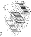
Fig. 2 is an exploded oblique view of the battery pack shown inFig. 1 ; -
Fig. 3 is an oblique view from the backside of the battery pack shown inFig. 2 ; -
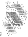
Fig. 4 is an exploded oblique view with one part enlarged of the battery assembly of the battery pack shown inFig. 2 ; -
Fig. 5 is an exploded oblique view of the battery assembly shown inFig. 4 ; -
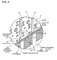
Fig. 6 is an enlarged oblique view partly in cross-section of an important part of the battery pack shown inFig. 1 ; -
Fig. 7 is an exploded oblique view of a battery pack for another embodiment of the present invention; and -
Fig. 8 is an enlarged oblique view showing another example of the lead-plates. - The following describes embodiments of the present invention based on the figures. The battery pack of
Figs. 1-6 has abattery assembly 9 housed in anexternal case 2. Thebattery assembly 9 has a plurality of batteries 1 that can be charged connected in series and parallel by lead-plates 3. [external case] - The external case shown in
Figs. 2 ,3 , and6 houses abattery assembly 9 and has a box-shape withheat radiating sections 10 on opposing surfaces to radiate heat away from the batteries 1. Although theexternal case 2 of the figures hasheat radiating sections 10 provided on both opposing side-walls, the external case can also have a heat radiating section on only one of its opposing side-walls. Theexternal case 2 of the figures has rectangularheat radiating sections 10, andperimeter walls 11 connected around those rectangularheat radiating sections 10. Each battery 1 is loaded in thebattery assembly 9 with an orientation that is perpendicular to theexternal case 2heat radiating sections 10, and all theelectrodes 1A of the batteries 1 are disposed opposite the inside surface of aheat radiating section 10. For a battery pack that houses abattery assembly 9 in theexternal case 2 in this manner, all the batteries 1 are contained in theexternal case 2 in parallel orientation. Since lead-plates 3 are connected to theelectrodes 1A at the ends of all the batteries 1, the lead-plates 3 are disposed between the batteries 1 and theheat radiating sections 10. - The
external case 2 is made of molded plastic. Theexternal case 2 is provided with inward protrudingregions 12 on the inside surfaces of theheat radiating sections 10 to make surface-to-surface contact and thermal connection with the lead-plates 3 disposed inside. The protruding surfaces of the inward protrudingregions 12 are thermally joined to the surfaces of the lead-plates 3. As shown inFig. 6 , the protruding surfaces of the inward protrudingregions 12 tightly contact the surfaces of the lead-plates 3 directly. Or, as shown inFig. 7 , the protruding surfaces of the inward protrudingregions 12 tightly contact the lead-plates 3 through flexibleheat transfer sheet 7. Further, by establishing inward protrudingregions 12 at theexternal case 2heat radiating sections 10,depressions 13 can be established in the outside surfaces of the inward protrudingregions 12, andheat radiating fins 14 are molded in single-piece construction with thedepressions 13. - The
battery assembly 9 ofFigs. 2-4 has a plurality of lead-plates 3 disposed in a separated manner on both sides of thebattery assembly 9. Theexternal case 2 has a plurality of inward protrudingregions 12 established to make thermal connection with the surface of each lead-plate 3. Thebattery assembly 9 of the figures has batteries 1 arranged in fixed positions in a plasticinner case 4. Theinner case 4 is provided with a plurality of columns of recessedregions 21 to dispose the plurality of lead-plates 3 in fixed positions and parallel orientation. As shown inFigs. 2 ,3 , and6 , theexternal case 2 is provided with a plurality of inward protrudingregions 12 in theheat radiating sections 10 that insert into each recessedregion 21. The outlines of the inward protrudingregions 12 are shaped to fit in the recessedregions 21 and hold thebattery assembly 9 in a fixed position inside theexternal case 2. The outlines of the inward protrudingregions 12 are made slightly smaller than the size of the interiors of the recessedregions 21, and the inward protrudingregions 12 insert into the recessedregions 21 in a manner that prevents position shift. By inserting the inward protrudingregions 12 of theexternal case 2 into theinner case 4 recessedregions 21, position shift between theexternal case 2 and thebattery assembly 9 can be prevented. Consequently, thisexternal case 2 can house thebattery assembly 9 in a fixed position, and the inward protrudingregions 12 can be thermally connected to the surfaces of the lead-plates 3. - In the
external case 2 shown inFigs. 2 ,3 , and6 ,heat radiating fins 14 are established with thedepressions 13 in a manner that does not project out from theheat radiating sections 10. Theheat radiating fins 14 of the figures are rows of projections disposed in an intersecting manner. Theseheat radiating fins 14 can reinforce theheat radiating sections 10 while increasing the area for heat radiation. In particular,heat radiating fins 14 that are arrays of rows of intersecting projections reinforce the inward protrudingregions 12 and prevent vertical and horizontal deformation of those inward protrudingregions 12. This allows the protruding surfaces of the inward protrudingregions 12 to stably press against the surfaces of the lead-plates 3 for thermal connection. In addition, a configuration ofheat radiating fins 14 established withdepressions 13 in a manner that does not project from the surfaces of theexternal case 2 does not increase the size of theexternal case 2 with projecting fins, and can prevent damage to theheat radiating fins 14 caused by projection from the surface. However, the heat radiating fins can also be made taller to project from the surfaces of the external case to increase the heat radiating area and improve the heat radiating efficiency. Although theheat radiating fins 14 described above are established with thedepressions 13, the heat radiating fins can also be local protrusions in depressions or hill-and-valley shapes within depressions. However, it is not always necessary to establish heat radiating fins with the depressions on the outside surfaces of the inward protruding regions of the external case heat radiating sections. Here, the surfaces of the external case inward protruding regions are put in contact with the surfaces of the lead-plates for thermal connection and heat is radiated to the outside from inside the depressions. - The
external case 2 is molded from plastic resin such as acrylonitrile-butadiene-styrene (ABS) resin. Theexternal case 2 is divided into two parts at the middle of theperimeter walls 11, and is connected together by a fastening method such as screw-fastening or snap-fit connection. Theexternal case 2 can be designed in various sizes and shapes depending on the battery pack application, purpose, operating conditions, and the size, shape, and number of batteries employed. Theexternal case 2 shown inFigs. 1-3 is divided into a firstexternal case 2A and a secondexternal case 2B. Theexternal case 2 of the figures is provided withattachment extensions 15 on its perimeter surfaces to connect the firstexternal case 2A and the secondexternal case 2B. The firstexternal case 2A and the secondexternal case 2B are joined together by connectingcorresponding attachment extensions 15 together. Theexternal case 2 is fastened together by screw-fastening. The firstexternal case 2A and the secondexternal case 2B are approximately symmetrical. Here, the battery pack is used with theexternal case 2 in the standing orientation shown in the figures, namely with one of theperimeter walls 11 at the bottom. However, theexternal case 2 can also be used with one of theheat radiating section 10 surfaces, which is provided withheat radiating fins 14, at the bottom. In addition, in other battery pack embodiments that include anexternal case 2, the bottom surface of theexternal case 2 can be selected depending on battery pack operating conditions. -
Figs. 2-5 show thebattery assembly 9. Thebattery assembly 9 of those figures is provided with batteries 1 that can be charged and are disposed next to each other in parallel orientation, aninner case 4 that disposes the batteries 1 in fixed positions, and a plurality of lead-plates 3 weld-attached toelectrodes 1A at the ends of each battery 1 disposed in theinner case 4 to electrically connect adjacent batteries 1. - The batteries 1 of the figures are circular cylindrical batteries. A plurality of batteries 1 are arranged in multiple rows and columns with the
electrodes 1A at each end of the batteries 1 positioned in common planes. Thebattery assembly 9 of the figures is an array of batteries 1 with six horizontal rows and fourteen vertical columns. Batteries 1 in adjacent columns are shifted vertically to position batteries 1 in one column midway between batteries 1 in an adjacent column. This allows circular cylindrical batteries 1 to be arrayed in multiple columns in close proximity. However, the battery pack of the present invention is not limited to a configuration having the number and arrangement of batteries described above. For example, batteries can also be disposed in a rectangular grid arrangement (no column shifting). - The batteries 1 are batteries that can be charged. Circular cylindrical batteries are used as the batteries 1 in the battery pack of the figures, although rectangular batteries and thin-outline batteries can also be used. In the present embodiment, circular cylindrical lithium ion batteries are used as the batteries 1. Lithium ion batteries are suitable for use in a high capacity, high output battery pack. This is because lithium ion batteries can achieve high capacity-to-weight and capacity-to-volume ratios. However, the battery pack of the present invention is not limited to the use of lithium ion batteries, and rechargeable batteries such as nickel-hydride batteries and nickel-cadmium batteries can also be used.
- The
battery assembly 9 shown inFig. 5 has batteries 1 inserted in specified positions ininner case 4battery loading sections 22. As shown inFig. 5 , theinner case 4 is formed in a shape that has circular cylindricalbattery loading sections 22. Thebattery loading sections 22 are formed with interior shapes that can accept circular cylindrical battery insertion. Theinner case 4 of the figures is provided with eighty-fourbattery loading sections 22 to insert batteries 1 in six rows and fourteen columns. Both ends of thebattery loading sections 22 are open. The battery pack ofFig. 5 has aninner case 4 that is divided into two pieces in the lengthwise direction of the cylindrical batteries 1 (left and right in the figure). The left and rightinner case 4 pieces are formed with both ends of thebattery loading sections 22 open to accept circular cylindrical batteries 1. Theinner case 4 is molded with an insulating material such as plastic. Aninner case 4 molded from plastic in a shape establishingbattery loading sections 22 can dispose the plurality of batteries 1 in an array of separate compartments that accurately align those batteries 1 in specified positions. Further, by separating the batteries 1 in independent compartments, conditions that induce battery 1 thermal runaway can be prevented. The connectedinner case 4, which is molded as two pieces, exposes theelectrodes 1A at the ends of the batteries 1 to the outside from the open ends of thebattery loading sections 22. The lead-plates 3 are weld-attached to the exposedelectrodes 1A by a technique such as spot-welding or laser-welding. Polycarbonate can be used as theinner case 4 plastic material. This material has high strength and is not easily dissolved by lithium ion battery electrolyte that could leak from a battery. Conversely, ABS resin is easily dissolved by lithium ion battery electrolyte and its use is undesirable. - The
inner case 4 is provided with recessedregions 21 formed to hold lead-plates 3 in fixed positions at both open ends of thebattery loading sections 22. The lead-plates 3 are inserted into the recessedregions 21 and connected to theelectrodes 1A at the ends of the batteries 1. Consequently, the recessedregions 21 are positioned to dispose the lead-plates 3 for connection to the battery 1electrodes 1A. - The lead-
plates 3 are inserted into theinner case 4 recessedregions 21 and spot-welded or laser-welded to the battery 1electrodes 1A to connect adjacent batteries 1 in series and parallel. In thebattery assembly 9 ofFigs. 2-4 , a plurality of lead-plates 3 is disposed in parallel orientation with an insulatinggap 6 established between each lead-plate 3 and weld-attached to the battery 1electrodes 1A. Thebattery assembly 9 ofFig. 4 has seven columns of lead-plates 3 disposed at one end of the batteries 1 (upper left end inFig. 4 ), and each lead-plate 3 is connected to two columns of batteries 1 with six batteries 1 in each column. Eight columns of lead-plates 3 are disposed at the other end of the batteries 1 (lower right end inFig. 4 ) with the lead-plates 3 at both sides acting as output lead-plates 3X that connect one column of six batteries 1. The remaining six columns of lead-plates 3 connect two columns of batteries 1 with six batteries 1 in each column. These lead-plates 3 connect the six batteries 1 in one column in parallel, and connect batteries 1 in adjacent columns in series. Specifically, the eighty-four batteries 1 are connected with six batteries 1 in parallel and fourteen batteries 1 in series. The output lead-plates 3X disposed at both sides of the lower right end of the batteries 1 inFig. 4 connect six parallel by fourteen series (eighty-four) batteries 1 tooutput terminals 36. Each output lead-plate 3X is provided with anoutput extension 3B on a side edge to connect to anoutput terminal 36. Each output lead-plate 3X has a band-shaped connecting section that connects six batteries 1 in parallel and a bent section on a side edge that is theoutput extension 3B disposed on a side of theinner case 4 and connected to anoutput terminal 36. Since theoutput extension 3B of an output lead-plate 3X is formed in a wide plate-shape, the electrical resistance of theoutput extension 3B can be made small. InFig. 4 , the output lead-plate 3X output extension 3B disposed on the left side is connected to theoutput terminal 36 through aprotection device 37. Thisprotection device 37 is a device that can cut-off excessive current flow such as a fuse, a circuit breaker, or a positive thermal coefficient (PTC) current limiting device. Theoutput terminals 36 connected to the output lead-plates 3B on both sides are exposed to the outside through openings 16 (refer toFigs. 2 and3 ) provided in theattachment extensions 15 of theexternal case 2. Further, as shown inFig. 1 , theoutput terminals 36 exposed outside theexternal case 2 are connected topower cords 40 viabolts 41 to supply power to electrical equipment. In theexternal case 2 shown in the figures, insulatingbarriers 17 are formed in single-piece construction with theexternal case 2 on theattachment extensions 15 projecting from the sides of the exposedoutput terminals 36. Theoutput terminal 36 andpower cord 40 connection regions are protected by these insulatingbarriers 17. - The lead-
plates 3 are made from sheet-metal with low electrical resistance and superior thermal conductivity. For example, nickel, iron, steel, copper, and copper alloys in sheet-metal form can be plated with a metal such as nickel and used as the lead-plates 3. A sheet-metal thickness that is optimum for weld-attachment, for example, 0.1mm to 0.3mm sheet-metal can be used as the lead-plates 3. If the lead-plates 3 are too thick or too thin, they cannot be spot-welded or laser-welded to theelectrodes 1A at the ends of the batteries 1 with an ideal weld-attach. Since a lead-plate that is too thick requires a large amount of thermal energy for heating and fusing, detrimental effects on the batteries increase. Conversely, a lead-plate that is too thin has high electrical and thermal resistance, and does not have sufficient mechanical strength. Therefore, lead-plate thickness is set to an optimum value considering the amount of current flow and the type of application. - The lead-
plates 3 ofFigs. 4 and6 are provided withslits 31 in locations that are spot-welded to the battery 1electrodes 1A to reduce the flow of ineffective welding current. The lead-plates 3 of the figures are provided withvertical slits 31A, andhorizontal slits 31B separated from thevertical slits 31A above and below thevertical slits 31A. Spot-welding electrodes are pressed onto both sides of avertical slit 31 A to weld-attach the lead-plate 3 on both sides of thevertical slit 31A to anelectrode 1A at the end of a battery 1. Further, the lead-plates 3 haveextensions 3A established at their upper ends for connection to acircuit board 5. The lead-plate 3extensions 3A are connected to thecircuit board 5 via leads 35. - A lead-
plate 3 connected to battery 1electrodes 1A by weld-attachment is stably connected to the batteries 1. The lead-plates 3 ofFig. 8 are provided withflexible pressure tabs 33 made of flexibly deformable sheet-metal that press resiliently against theelectrodes 1A at the ends of the batteries 1. Theflexible pressure tabs 33 are bent to resiliently protrude towards the battery 1electrodes 1A. These lead-plates 3 are pressed towards the battery 1electrodes 1A by theexternal case 2 inward protrudingregions 12 to electrically connect theflexible pressure tabs 33 with theelectrodes 1A. The lead-plates 3 ofFig. 8 are provided with a plurality offlexible pressure tabs 33 that extend from the centers of the battery 1electrodes 1A in patterns that radiate outward towards theelectrode 1A perimeters. Eachflexible pressure tab 33 becomes wider from the center of anelectrode 1A towards theelectrode 1A perimeter. In addition, gaps are established betweenflexible pressure tabs 33 for a configuration that allows eachtab 33 to press against anelectrode 1A without interference fromadjacent tabs 33. In this type of lead-plate 3, electrical connection is made by each of a plurality offlexible pressure tabs 33 pressing independently against anelectrode 1A to resolve electrical connection problems. This is because electrical connection to anelectrode 1A can be made by any of the manyflexible pressure tabs 33. In this type of lead-plate 3,flexible pressure tabs 33 press against battery 1electrodes 1A, and in reaction to that pressure force, the lead-plate 3 is pressed resiliently against the surface of an inwardprotruding region 12. Specifically, the resilience of theflexible pressure tabs 33 presses the tips of the tabs against the battery 1electrodes 1A in a flexible manner, and presses the parts of the lead-plate 3 with noflexible pressure tabs 33 against the surface of the inwardprotruding region 12 in a flexible manner. Consequently, while resolving connection problems between the lead-plates 3 and battery 1electrodes 1A, this structure also puts the lead-plates 3 in good contact with the inward protrudingregions 12 for effective heat transfer from the battery 1electrodes 1A to the inward protrudingregions 12. Further, since the lead-plates 3 do not separate from the battery 1electrodes 1A due to conditions such as vibration, this battery pack is suitable for applications accompanied by vibration such as in a vehicle battery pack. - The
circuit board 5 that is connected to each lead-plate 3 has electronic parts mounted to implement battery 1 charging control, protection circuitry, and remaining battery capacity computation circuitry. In addition, thecircuit board 5 acquires and computes various data such as remaining capacity, abnormal conditions, discharge suspension (commands), and charging suspension (commands). These data are transmitted vialead wires 38 to the electrical equipment that is supplied with power from the battery pack (for example, a two-wheeled vehicle). The electrical equipment performs various control operations based on these data. Theexternal case 2 shown inFigs. 1-3 is provided with a lead wire opening 18 through theupper perimeter wall 11 to pass thelead wires 38. Thelead wires 38 are run to the outside through thelead wire opening 18. - As shown in
Figs. 2-5 , thecircuit board 5 is attached to the upper surface of theinner case 4. Theinner case 4 is provided with a plurality ofalignment ribs 23 formed in single-piece construction with theinner case 4 around thecircuit board 5 to align thecircuit board 5 in a specified position. Thecircuit board 5 is guided into a specified position surrounded by thealignment ribs 23 on the upper surface of theinner case 4, and fastened in that position by screws. - The protection circuitry mounted on the
circuit board 5 is circuitry such as a circuit to detect battery 1 over-charging and over-discharging and to control current, and a circuit to detect battery over-charging and cut-off current. To detect battery 1 over-charging and over-discharging, the protection circuitry is provided with a voltage detection circuit (not illustrated) that detects battery 1 voltage. The voltage detection circuit detects the voltage of the batteries 1 via the lead-plates 3 and prevents over-charging and over-discharging. - The battery pack shown in
Fig. 7 has flexibleheat transfer sheet 7 disposed between the inside surfaces of theexternal case 2 and the surfaces of the lead-plates 3. Inward protrudingregions 12 of theexternal case 2 make tight contact with the surfaces of the lead-plates 3 via the flexibleheat transfer sheet 7. The flexibleheat transfer sheet 7 is sandwiched between the lead-plates 3 and the inside surfaces of theexternal case 2 to transfer heat from the lead-plates 3 to theexternal case 2. The flexibleheat transfer sheet 7 is resilient, cushioning sheet with superior heat conductivity such as resilient silicone resin sheet. Although not illustrated, a flexibleheat transfer sheet 7 has one side in tight contact with the lead-plates 3 and the other side in tight contact with the inward protrudingregions 12 of theexternal case 2 to efficiently transfer lead-plate 3 heat to theexternal case 2. Flexibleheat transfer sheet 7 in tight contact with both the lead-plates 3 and theexternal case 2 efficiently transfers lead-plate 3 heat to theexternal case 2, and battery 1 heat is effectively radiated through the lead-plates 3 out of theexternal case 2. The flexibleheat transfer sheet 7 can be made thick and tightly attached to both the lead-plates 3 and the inside surfaces of theexternal case 2. Conversely, the flexibleheat transfer sheet 7 can be made thin to efficiently transfer lead-plate 3 heat to theexternal case 2. Therefore, thickness of the flexibleheat transfer sheet 7 is made, for example, 0.5mm to 3mm considering the lead-plate 3 toexternal case 2 contact tightness and thermal conductivity. The flexibleheat transfer sheet 7 described above is slightly squeezed together by connecting the firstexternal case 2A and the secondexternal case 2B together to contain thebattery assembly 9 inside theexternal case 2. The lead-plates 3 on one side and the inside surfaces of theexternal case 2 on the other side make tight contact with the flexibleheat transfer sheet 7 due to resilient restoring forces in the squeezed flexibleheat transfer sheet 7. - The battery pack described above is assembled in the following manner.
- (1) As shown in
Fig. 5 , a plurality of batteries 1 are inserted with prescribed orientation (polarity) intobattery loading sections 22 in theinner case 4. The batteries 1 of the figures are inserted in the same direction (polarity) in vertical columns, and in alternating reverse directions (polarities) in lateral left-to-right rows. After loading all the batteries 1 in theinner case 4battery loading sections 22, the pair ofinner case 4 pieces are fastened together. - (2) As shown in
Fig. 4 , thecircuit board 5 is mounted on top of theinner case 4. Thecircuit board 5 is aligned inside thealignment ribs 23 on the upper surface of theinner case 4 and attached via screws. - (3) The lead-
plates 3 are positioned inside the recessedregions 21 of theinner case 4 and weld-attached to theelectrodes 1A at the ends of each battery 1. The lead-plates 3 are weld-attached to the battery 1electrodes 1A exposed from the open ends of theinner case 4battery loading sections 22 by a technique such as spot-welding or laser-welding. Adjacent lead-plates 3 are disposed in columns separated by insulatinggaps 6 to avoid contact. Lead-plate 3extensions 3A are connected to thecircuit board 5 via leads 35. - (4) As shown in
Figs. 2 and3 , thebattery assembly 9 is enclosed inside theexternal case 2. Here, inward protrudingregions 12 on the inside surfaces of theexternal case 2heat radiating sections 10 are disposed opposite thebattery assembly 9 lead-plates 3 to thermally couple the lead-plates 3 to the surfaces of the inward protrudingregions 12. The surfaces of the inward protruding regions shown inFig. 6 make tight, direct contact with the surfaces of the lead-plates 3 for thermal connection. In the battery pack shown inFig. 7 , flexibleheat transfer sheet 7 is sandwiched between the lead-plates 3 and the inside surfaces of theexternal case 2, and the inward protrudingregions 12 are put in tight contact and thermally coupled with the lead-plates 3 via the flexibleheat transfer sheet 7. Thebattery assembly 9 is installed in theexternal case 2 with the lead-plates 3 in tight, direct contact with the inside surfaces of theexternal case 2 for thermal connection, or with the lead-plates 3 in tight thermal contact with the inside surfaces of theexternal case 2 via flexibleheat transfer sheet 7. - (5) The first
external case 2A and secondexternal case 2A of theexternal case 2 are joined together. - The battery pack of the present invention is suitable for use in applications that connect a plurality of batteries in parallel and connect those parallel connected batteries in series for higher output. For example, the battery pack can be used favorably in applications such as an electric wheel chair, an electric powered bicycle, an electric powered scooter or motorcycle, an electric tool, and a dedicated operation robot.
- The present application is based on Application No.
2008-233712 -
- 1
- BATTERY
- 1A
- ELECTRODE
- 2
- EXTERNAL CASE
- 2A
- FIRST EXTERNAL CASE
- 2B
- SECOND EXTERNAL CASE
- 3
- LEAD-PLATE
- 3X
- OUTPUT LEAD-PLATE
- 3A
- EXTENSION
- 3B
- OUTPUT EXTENSION
- 4
- INNER CASE
- 5
- CIRCUIT BOARD
- 6
- INSULATING GAP
- 7
- FLEXIBLE HEAT TRANSFER SHEET
- 9
- BATTERY ASSEMBLY
- 10
- HEAT RADIATING SECTION
- 11
- PERIMETER WALLS
- 12
- INWARD PROTRUDING REGION
- 13
- DEPRESSION
- 14
- HEAT RADIATING FIN
- 15
- ATTACHMENT EXTENSION
- 16
- OPENING
- 17
- INSULATING BARRIER
- 18
- LEAD WIRE OPENING
- 21
- RECESSED REGION
- 22
- BATTERY LOADING SECTION
- 23
- ALIGNMENT RIB
- 31
- SLITS
- 31A
- VERTICAL SLITS
- 31B
- HORIZONTAL SLITS
- 33
- FLEXIBLE PRESSURE TAB
- 35
- LEAD
- 36
- OUTPUT TERMINAL
- 37
- PROTECTION DEVICE
- 38
- LEAD WIRES
- 40
- POWER CORD
- 41
- BOLT
Claims (16)
- A battery pack comprising:a plurality of batteries (1) that can be charged;lead-plates (3) that connect to electrodes (1A) at the ends of the batteries (1); andan external case (2) that houses a battery assembly (9) with the batteries (1) connected via the lead-plates (3),
characterized in thatthe external case (2) has a heat radiating section (10) established on at least one of its opposing surfaces to radiate battery (1) heat; batteries (1) are disposed in parallel orientation with the electrodes (1A) at the ends of the batteries (1) opposite the inside surface of the heat radiating section (10); the battery assembly (9) is housed inside the external case (2) disposing the lead-plates (3) connecting battery (1) electrodes (1A) at the inside surface of the heat radiating section (10) to thermally couple the lead-plates (3) to the inside surface of the heat radiating section (10);wherein the external case (2) is made of plastic and provided with inward protruding regions (12) on the inside surface of the heat radiating section (10); the inward protruding regions (12) make surface contact and thermally couple with the lead-plates (3) disposed inside the external case (2); the heat radiating section (10) has depressions (13) in the outside surfaces of the inward protruding regions (12); and battery (1) heat is transferred from the lead-plates (3) to the heat radiating section (10) inward protruding regions (12) and radiated from the external case (2) to the outside. - The battery pack as cited in claim 1 wherein the external case (2) has heat radiating sections (10) on both opposing surfaces.
- The battery pack as cited in claim 1 wherein heat radiating fins (14) are formed in single-piece construction in the depressions (13) of the heat radiating section (10).
- The battery pack as cited in claim 3 wherein the external case (2) is provided with heat radiating fins (14) in the depressions (13) of the heat radiating section (10) that do not protrude from the surface of the heat radiating section (10).
- The battery pack as cited in claim 4 wherein heat radiating fins (14) are arrays of a plurality of rows of intersecting projections.
- The battery pack as cited in claim 1 wherein an inner case (4) is provided to dispose the batteries (1) in fixed positions.
- The battery pack as cited in claim 6 wherein the inner case (4) has battery loading sections (22) that are open at both ends and accept battery (1) insertion into fixed positions; recessed regions (21) are provided in battery loading section (22) surfaces to dispose the lead-plates (3), which are connected to the electrodes (1A) at the ends of the batteries (1) loaded in the battery loading sections (22), in fixed positions; the outlines of the inward protruding regions (12) established in the external case (2) heat radiating section (10) are shaped to allow insertion into the recessed regions (21) for retention in fixed positions; and the inward protruding regions (12) are aligned and inserted into the recessed regions (21) to thermally couple the inward protruding regions (12) to the lead-plates (3).
- The battery pack as cited in claim 6 wherein the inner case (4) has a plurality of recessed regions (21) to dispose a plurality of lead-plates (3) in fixed positions and in parallel orientation; and the external case (2) heat radiating section (10) is provided with a plurality of inward protruding regions (12) that insert into each recessed region (21).
- The battery pack as cited in claim 8 wherein the inward protruding regions (12) have outlines shaped smaller than the insides of the recessed regions (21), and the inward protruding regions (12) insert into the recessed regions (21) in a manner that does not shift in position.
- The battery pack as cited in claim 1 wherein flexible heat transfer sheet (7) is sandwiched between external case (2) inward protruding region (12) surfaces and the lead-plates (3).
- The battery pack as cited in claim 10 wherein the flexible heat transfer sheet (7) is flexible sheet made from silicone resin.
- The battery pack as cited in claim 10 wherein the flexible heat transfer sheet (7) has one side in tight contact with the lead-plates (3) and the other side in tight contact with the inward protruding regions (12) of the external case (2) to transfer lead-plate (3) heat to the external case (2).
- The battery pack as cited in claim 1 wherein the lead-plates (3) are flexibly deformable sheet-metal and have flexible pressure tabs (33) that resiliently press against the battery (1) electrodes (1A); and the flexible pressure tabs (33) resiliently protrude towards the battery (1) electrodes (1A) and press against the electrodes (1A) for electrical connection.
- The battery pack as cited in claim 13 wherein the flexible pressure tabs (33) are a plurality of flexible pressure tabs (33) that extend from the centers of the battery (1) electrodes (1A) in patterns that radiate outward towards the electrode (1A) perimeters.
- The battery pack as cited in claim 14 wherein the flexible pressure tabs (33) becomes wider from the center of an electrode (1A) towards the electrode (1A) perimeter.
- The battery pack as cited in claim 1 wherein the lead-plates (3) are weld-attached for connection to the electrodes (1A) at the ends of the batteries (1).
Priority Applications (2)
| Application Number | Priority Date | Filing Date | Title |
|---|---|---|---|
| EP20100002451 EP2365560B1 (en) | 2010-03-09 | 2010-03-09 | Battery pack with lead-plates |
| AT10002451T ATE557433T1 (en) | 2010-03-09 | 2010-03-09 | BATTERY PACK WITH CABLE PLATES |
Applications Claiming Priority (1)
| Application Number | Priority Date | Filing Date | Title |
|---|---|---|---|
| EP20100002451 EP2365560B1 (en) | 2010-03-09 | 2010-03-09 | Battery pack with lead-plates |
Publications (2)
| Publication Number | Publication Date |
|---|---|
| EP2365560A1 EP2365560A1 (en) | 2011-09-14 |
| EP2365560B1 true EP2365560B1 (en) | 2012-05-09 |
Family
ID=42238523
Family Applications (1)
| Application Number | Title | Priority Date | Filing Date |
|---|---|---|---|
| EP20100002451 Active EP2365560B1 (en) | 2010-03-09 | 2010-03-09 | Battery pack with lead-plates |
Country Status (2)
| Country | Link |
|---|---|
| EP (1) | EP2365560B1 (en) |
| AT (1) | ATE557433T1 (en) |
Families Citing this family (6)
| Publication number | Priority date | Publication date | Assignee | Title |
|---|---|---|---|---|
| JP2013109977A (en) * | 2011-11-21 | 2013-06-06 | Yamaha Motor Co Ltd | Battery pack and saddle-ride vehicle having the same |
| CN105514312A (en) * | 2015-12-08 | 2016-04-20 | 合普新能源科技有限公司 | Automotive lithium ion battery module and semi-finished product module thereof |
| ITUA20164736A1 (en) | 2016-06-29 | 2017-12-29 | Ferrari Spa | BATTERY MODULE FOR AN ELECTRICITY ACCUMULATION SYSTEM FOR A VEHICLE WITH ELECTRIC PROPULSION |
| WO2019208219A1 (en) * | 2018-04-25 | 2019-10-31 | 三洋電機株式会社 | Power supply device |
| EP3952008B8 (en) * | 2019-03-28 | 2023-07-26 | Panasonic Energy Co., Ltd. | Power supply device |
| CN113611976B (en) * | 2021-07-22 | 2023-02-24 | 深圳市沃尔德电子有限公司 | Lithium battery protection device for scooter for old people |
Family Cites Families (3)
| Publication number | Priority date | Publication date | Assignee | Title |
|---|---|---|---|---|
| JP4127501B2 (en) * | 2002-11-19 | 2008-07-30 | 松下電器産業株式会社 | Battery connection structure, battery module, and battery pack |
| JP4640348B2 (en) * | 2007-02-01 | 2011-03-02 | トヨタ自動車株式会社 | Power supply |
| JP2009176689A (en) * | 2008-01-28 | 2009-08-06 | Sanyo Electric Co Ltd | Battery pack |
-
2010
- 2010-03-09 AT AT10002451T patent/ATE557433T1/en active
- 2010-03-09 EP EP20100002451 patent/EP2365560B1/en active Active
Also Published As
| Publication number | Publication date |
|---|---|
| ATE557433T1 (en) | 2012-05-15 |
| EP2365560A1 (en) | 2011-09-14 |
Similar Documents
| Publication | Publication Date | Title |
|---|---|---|
| JP5244513B2 (en) | Battery pack | |
| US11139515B2 (en) | Battery module having heat conduction pad | |
| EP3664187B1 (en) | Cylindrical battery cell assembly with improved space utilization and safety, and battery module comprising same | |
| JP5478099B2 (en) | Battery pack | |
| EP2355205B1 (en) | Battery system with a plurality of batteries housed in an external case | |
| US11870046B2 (en) | Battery pack | |
| EP1839349B1 (en) | Sensing board assembly for secondary battery module | |
| KR100700277B1 (en) | Cartridge-type battery pack | |
| EP2355209B1 (en) | Battery system with service plug connection | |
| US7538516B2 (en) | Separable connecting member for secondary battery module and method of improving the performance of battery module by leveling voltage | |
| EP2365560B1 (en) | Battery pack with lead-plates | |
| KR20190064887A (en) | Battery Module Having Heat Dissipation Plate | |
| CN107925140B (en) | Battery pack | |
| WO2008147153A1 (en) | Electrical connecting member of assembling type and secondary battery pack containing the same | |
| KR102587699B1 (en) | Battery Pack | |
| EP3694016B1 (en) | Secondary battery pack including cell frame with coating prevention part | |
| KR20170060451A (en) | Battery pack | |
| KR102116187B1 (en) | Battery pack of improved holder for energy storage system | |
| CN102195010B (en) | Battery pack with guide plate | |
| KR20210151471A (en) | Rechargeable battery pack | |
| TWI442615B (en) | Battery pack with lead plate | |
| CN114467217B (en) | Battery module and battery pack including the same | |
| CN112042004B (en) | Battery module comprising a module housing | |
| WO2018179794A1 (en) | Battery pack |
Legal Events
| Date | Code | Title | Description |
|---|---|---|---|
| PUAI | Public reference made under article 153(3) epc to a published international application that has entered the european phase |
Free format text: ORIGINAL CODE: 0009012 |
|
| 17P | Request for examination filed |
Effective date: 20101126 |
|
| AK | Designated contracting states |
Kind code of ref document: A1 Designated state(s): AT BE BG CH CY CZ DE DK EE ES FI FR GB GR HR HU IE IS IT LI LT LU LV MC MK MT NL NO PL PT RO SE SI SK SM TR |
|
| AX | Request for extension of the european patent |
Extension state: AL BA ME RS |
|
| RIC1 | Information provided on ipc code assigned before grant |
Ipc: H01M 2/10 20060101AFI20110914BHEP Ipc: H01M 10/50 20060101ALI20110914BHEP Ipc: H01M 2/20 20060101ALI20110914BHEP |
|
| GRAP | Despatch of communication of intention to grant a patent |
Free format text: ORIGINAL CODE: EPIDOSNIGR1 |
|
| RAP1 | Party data changed (applicant data changed or rights of an application transferred) |
Owner name: SANYO ELECTRIC CO., LTD. Owner name: YAMAHA HATSUDOKI KABUSHIKI KAISHA |
|
| RIN1 | Information on inventor provided before grant (corrected) |
Inventor name: HAINO MASAMIC/O INTELLECTUAL PROPERTY H.Q. Inventor name: YONEDA HARUHIKOC/O INTELLECTUAL PROPERTY H.Q., Inventor name: FUKUKAWA KOUICHIC/O INTELLECTUAL PROPERTY H.Q., Inventor name: YONEYAMA SHINGOC/O INTELLECTUAL PROPERTY H.Q. |
|
| RIN1 | Information on inventor provided before grant (corrected) |
Inventor name: HAINO MASAMIC/O INTELLECTUAL PROPERTY H.Q. Inventor name: FUKUKAWA KOUICHIC/O INTELLECTUAL PROPERTY H.Q., Inventor name: TERADA JUNJIC/O YAMAHA HATSUDOKI KABUSHIKI KAISHA Inventor name: YONEYAMA SHINGOC/O INTELLECTUAL PROPERTY H.Q. Inventor name: KONDO TOSHIROC/O YAMAHA HATSUDOKI KABUSHIKI KAISHA Inventor name: YONEDA HARUHIKOC/O INTELLECTUAL PROPERTY H.Q., |
|
| GRAS | Grant fee paid |
Free format text: ORIGINAL CODE: EPIDOSNIGR3 |
|
| GRAA | (expected) grant |
Free format text: ORIGINAL CODE: 0009210 |
|
| AK | Designated contracting states |
Kind code of ref document: B1 Designated state(s): AT BE BG CH CY CZ DE DK EE ES FI FR GB GR HR HU IE IS IT LI LT LU LV MC MK MT NL NO PL PT RO SE SI SK SM TR |
|
| REG | Reference to a national code |
Ref country code: GB Ref legal event code: FG4D |
|
| REG | Reference to a national code |
Ref country code: CH Ref legal event code: EP Ref country code: AT Ref legal event code: REF Ref document number: 557433 Country of ref document: AT Kind code of ref document: T Effective date: 20120515 |
|
| REG | Reference to a national code |
Ref country code: IE Ref legal event code: FG4D |
|
| REG | Reference to a national code |
Ref country code: DE Ref legal event code: R096 Ref document number: 602010001280 Country of ref document: DE Effective date: 20120705 |
|
| REG | Reference to a national code |
Ref country code: NL Ref legal event code: VDEP Effective date: 20120509 |
|
| REG | Reference to a national code |
Ref country code: LT Ref legal event code: MG4D Effective date: 20120509 |
|
| PG25 | Lapsed in a contracting state [announced via postgrant information from national office to epo] |
Ref country code: NO Free format text: LAPSE BECAUSE OF FAILURE TO SUBMIT A TRANSLATION OF THE DESCRIPTION OR TO PAY THE FEE WITHIN THE PRESCRIBED TIME-LIMIT Effective date: 20120809 Ref country code: PL Free format text: LAPSE BECAUSE OF FAILURE TO SUBMIT A TRANSLATION OF THE DESCRIPTION OR TO PAY THE FEE WITHIN THE PRESCRIBED TIME-LIMIT Effective date: 20120509 Ref country code: SE Free format text: LAPSE BECAUSE OF FAILURE TO SUBMIT A TRANSLATION OF THE DESCRIPTION OR TO PAY THE FEE WITHIN THE PRESCRIBED TIME-LIMIT Effective date: 20120509 Ref country code: CY Free format text: LAPSE BECAUSE OF FAILURE TO SUBMIT A TRANSLATION OF THE DESCRIPTION OR TO PAY THE FEE WITHIN THE PRESCRIBED TIME-LIMIT Effective date: 20120509 Ref country code: LT Free format text: LAPSE BECAUSE OF FAILURE TO SUBMIT A TRANSLATION OF THE DESCRIPTION OR TO PAY THE FEE WITHIN THE PRESCRIBED TIME-LIMIT Effective date: 20120509 Ref country code: IS Free format text: LAPSE BECAUSE OF FAILURE TO SUBMIT A TRANSLATION OF THE DESCRIPTION OR TO PAY THE FEE WITHIN THE PRESCRIBED TIME-LIMIT Effective date: 20120909 Ref country code: FI Free format text: LAPSE BECAUSE OF FAILURE TO SUBMIT A TRANSLATION OF THE DESCRIPTION OR TO PAY THE FEE WITHIN THE PRESCRIBED TIME-LIMIT Effective date: 20120509 |
|
| REG | Reference to a national code |
Ref country code: AT Ref legal event code: MK05 Ref document number: 557433 Country of ref document: AT Kind code of ref document: T Effective date: 20120509 |
|
| PG25 | Lapsed in a contracting state [announced via postgrant information from national office to epo] |
Ref country code: GR Free format text: LAPSE BECAUSE OF FAILURE TO SUBMIT A TRANSLATION OF THE DESCRIPTION OR TO PAY THE FEE WITHIN THE PRESCRIBED TIME-LIMIT Effective date: 20120810 Ref country code: PT Free format text: LAPSE BECAUSE OF FAILURE TO SUBMIT A TRANSLATION OF THE DESCRIPTION OR TO PAY THE FEE WITHIN THE PRESCRIBED TIME-LIMIT Effective date: 20120910 Ref country code: LV Free format text: LAPSE BECAUSE OF FAILURE TO SUBMIT A TRANSLATION OF THE DESCRIPTION OR TO PAY THE FEE WITHIN THE PRESCRIBED TIME-LIMIT Effective date: 20120509 Ref country code: HR Free format text: LAPSE BECAUSE OF FAILURE TO SUBMIT A TRANSLATION OF THE DESCRIPTION OR TO PAY THE FEE WITHIN THE PRESCRIBED TIME-LIMIT Effective date: 20120509 Ref country code: SI Free format text: LAPSE BECAUSE OF FAILURE TO SUBMIT A TRANSLATION OF THE DESCRIPTION OR TO PAY THE FEE WITHIN THE PRESCRIBED TIME-LIMIT Effective date: 20120509 |
|
| PG25 | Lapsed in a contracting state [announced via postgrant information from national office to epo] |
Ref country code: BE Free format text: LAPSE BECAUSE OF FAILURE TO SUBMIT A TRANSLATION OF THE DESCRIPTION OR TO PAY THE FEE WITHIN THE PRESCRIBED TIME-LIMIT Effective date: 20120509 |
|
| PG25 | Lapsed in a contracting state [announced via postgrant information from national office to epo] |
Ref country code: CZ Free format text: LAPSE BECAUSE OF FAILURE TO SUBMIT A TRANSLATION OF THE DESCRIPTION OR TO PAY THE FEE WITHIN THE PRESCRIBED TIME-LIMIT Effective date: 20120509 Ref country code: AT Free format text: LAPSE BECAUSE OF FAILURE TO SUBMIT A TRANSLATION OF THE DESCRIPTION OR TO PAY THE FEE WITHIN THE PRESCRIBED TIME-LIMIT Effective date: 20120509 Ref country code: NL Free format text: LAPSE BECAUSE OF FAILURE TO SUBMIT A TRANSLATION OF THE DESCRIPTION OR TO PAY THE FEE WITHIN THE PRESCRIBED TIME-LIMIT Effective date: 20120509 Ref country code: SK Free format text: LAPSE BECAUSE OF FAILURE TO SUBMIT A TRANSLATION OF THE DESCRIPTION OR TO PAY THE FEE WITHIN THE PRESCRIBED TIME-LIMIT Effective date: 20120509 Ref country code: EE Free format text: LAPSE BECAUSE OF FAILURE TO SUBMIT A TRANSLATION OF THE DESCRIPTION OR TO PAY THE FEE WITHIN THE PRESCRIBED TIME-LIMIT Effective date: 20120509 Ref country code: RO Free format text: LAPSE BECAUSE OF FAILURE TO SUBMIT A TRANSLATION OF THE DESCRIPTION OR TO PAY THE FEE WITHIN THE PRESCRIBED TIME-LIMIT Effective date: 20120509 Ref country code: DK Free format text: LAPSE BECAUSE OF FAILURE TO SUBMIT A TRANSLATION OF THE DESCRIPTION OR TO PAY THE FEE WITHIN THE PRESCRIBED TIME-LIMIT Effective date: 20120509 |
|
| PG25 | Lapsed in a contracting state [announced via postgrant information from national office to epo] |
Ref country code: IT Free format text: LAPSE BECAUSE OF FAILURE TO SUBMIT A TRANSLATION OF THE DESCRIPTION OR TO PAY THE FEE WITHIN THE PRESCRIBED TIME-LIMIT Effective date: 20120509 |
|
| PLBE | No opposition filed within time limit |
Free format text: ORIGINAL CODE: 0009261 |
|
| STAA | Information on the status of an ep patent application or granted ep patent |
Free format text: STATUS: NO OPPOSITION FILED WITHIN TIME LIMIT |
|
| 26N | No opposition filed |
Effective date: 20130212 |
|
| REG | Reference to a national code |
Ref country code: DE Ref legal event code: R097 Ref document number: 602010001280 Country of ref document: DE Effective date: 20130212 |
|
| PG25 | Lapsed in a contracting state [announced via postgrant information from national office to epo] |
Ref country code: BG Free format text: LAPSE BECAUSE OF FAILURE TO SUBMIT A TRANSLATION OF THE DESCRIPTION OR TO PAY THE FEE WITHIN THE PRESCRIBED TIME-LIMIT Effective date: 20120809 |
|
| PG25 | Lapsed in a contracting state [announced via postgrant information from national office to epo] |
Ref country code: MC Free format text: LAPSE BECAUSE OF NON-PAYMENT OF DUE FEES Effective date: 20130331 Ref country code: ES Free format text: LAPSE BECAUSE OF FAILURE TO SUBMIT A TRANSLATION OF THE DESCRIPTION OR TO PAY THE FEE WITHIN THE PRESCRIBED TIME-LIMIT Effective date: 20120820 |
|
| REG | Reference to a national code |
Ref country code: IE Ref legal event code: MM4A |
|
| PG25 | Lapsed in a contracting state [announced via postgrant information from national office to epo] |
Ref country code: IE Free format text: LAPSE BECAUSE OF NON-PAYMENT OF DUE FEES Effective date: 20130309 |
|
| PG25 | Lapsed in a contracting state [announced via postgrant information from national office to epo] |
Ref country code: MT Free format text: LAPSE BECAUSE OF FAILURE TO SUBMIT A TRANSLATION OF THE DESCRIPTION OR TO PAY THE FEE WITHIN THE PRESCRIBED TIME-LIMIT Effective date: 20120509 |
|
| REG | Reference to a national code |
Ref country code: CH Ref legal event code: PL |
|
| PG25 | Lapsed in a contracting state [announced via postgrant information from national office to epo] |
Ref country code: CH Free format text: LAPSE BECAUSE OF NON-PAYMENT OF DUE FEES Effective date: 20140331 Ref country code: LI Free format text: LAPSE BECAUSE OF NON-PAYMENT OF DUE FEES Effective date: 20140331 |
|
| PG25 | Lapsed in a contracting state [announced via postgrant information from national office to epo] |
Ref country code: SM Free format text: LAPSE BECAUSE OF FAILURE TO SUBMIT A TRANSLATION OF THE DESCRIPTION OR TO PAY THE FEE WITHIN THE PRESCRIBED TIME-LIMIT Effective date: 20120509 |
|
| PG25 | Lapsed in a contracting state [announced via postgrant information from national office to epo] |
Ref country code: TR Free format text: LAPSE BECAUSE OF FAILURE TO SUBMIT A TRANSLATION OF THE DESCRIPTION OR TO PAY THE FEE WITHIN THE PRESCRIBED TIME-LIMIT Effective date: 20120509 |
|
| PG25 | Lapsed in a contracting state [announced via postgrant information from national office to epo] |
Ref country code: HU Free format text: LAPSE BECAUSE OF FAILURE TO SUBMIT A TRANSLATION OF THE DESCRIPTION OR TO PAY THE FEE WITHIN THE PRESCRIBED TIME-LIMIT; INVALID AB INITIO Effective date: 20100309 Ref country code: LU Free format text: LAPSE BECAUSE OF NON-PAYMENT OF DUE FEES Effective date: 20130309 Ref country code: MK Free format text: LAPSE BECAUSE OF FAILURE TO SUBMIT A TRANSLATION OF THE DESCRIPTION OR TO PAY THE FEE WITHIN THE PRESCRIBED TIME-LIMIT Effective date: 20120509 |
|
| REG | Reference to a national code |
Ref country code: FR Ref legal event code: PLFP Year of fee payment: 7 |
|
| REG | Reference to a national code |
Ref country code: FR Ref legal event code: PLFP Year of fee payment: 8 |
|
| REG | Reference to a national code |
Ref country code: FR Ref legal event code: PLFP Year of fee payment: 9 |
|
| REG | Reference to a national code |
Ref country code: DE Ref legal event code: R079 Ref document number: 602010001280 Country of ref document: DE Free format text: PREVIOUS MAIN CLASS: H01M0002100000 Ipc: H01M0050200000 |
|
| PGFP | Annual fee paid to national office [announced via postgrant information from national office to epo] |
Ref country code: FR Payment date: 20220118 Year of fee payment: 13 |
|
| PGFP | Annual fee paid to national office [announced via postgrant information from national office to epo] |
Ref country code: GB Payment date: 20230119 Year of fee payment: 14 Ref country code: DE Payment date: 20230110 Year of fee payment: 14 |
|
| REG | Reference to a national code |
Ref country code: DE Ref legal event code: R081 Ref document number: 602010001280 Country of ref document: DE Owner name: YAMAHA HATSUDOKI K.K., IWATA-SHI, JP Free format text: FORMER OWNERS: SANYO ELECTRIC CO., LTD., MORIGUCHI, OSAKA, JP; YAMAHA HATSUDOKI K.K., IWATA-SHI, SHIZUOKA-KEN, JP Ref country code: DE Ref legal event code: R081 Ref document number: 602010001280 Country of ref document: DE Owner name: PANASONIC ENERGY CO., LTD., MORIGUCHI-SHI, JP Free format text: FORMER OWNERS: SANYO ELECTRIC CO., LTD., MORIGUCHI, OSAKA, JP; YAMAHA HATSUDOKI K.K., IWATA-SHI, SHIZUOKA-KEN, JP |
|
| REG | Reference to a national code |
Ref country code: GB Ref legal event code: 732E Free format text: REGISTERED BETWEEN 20231116 AND 20231122 |