EP3952004A1 - Batteriemodul und vorrichtung - Google Patents
Batteriemodul und vorrichtung Download PDFInfo
- Publication number
- EP3952004A1 EP3952004A1 EP20832295.8A EP20832295A EP3952004A1 EP 3952004 A1 EP3952004 A1 EP 3952004A1 EP 20832295 A EP20832295 A EP 20832295A EP 3952004 A1 EP3952004 A1 EP 3952004A1
- Authority
- EP
- European Patent Office
- Prior art keywords
- battery module
- temperature sensor
- temperature
- top cover
- circuit board
- Prior art date
- Legal status (The legal status is an assumption and is not a legal conclusion. Google has not performed a legal analysis and makes no representation as to the accuracy of the status listed.)
- Granted
Links
Images


Classifications
-
- H—ELECTRICITY
- H01—ELECTRIC ELEMENTS
- H01M—PROCESSES OR MEANS, e.g. BATTERIES, FOR THE DIRECT CONVERSION OF CHEMICAL ENERGY INTO ELECTRICAL ENERGY
- H01M50/00—Constructional details or processes of manufacture of the non-active parts of electrochemical cells other than fuel cells, e.g. hybrid cells
- H01M50/20—Mountings; Secondary casings or frames; Racks, modules or packs; Suspension devices; Shock absorbers; Transport or carrying devices; Holders
- H01M50/204—Racks, modules or packs for multiple batteries or multiple cells
- H01M50/207—Racks, modules or packs for multiple batteries or multiple cells characterised by their shape
- H01M50/209—Racks, modules or packs for multiple batteries or multiple cells characterised by their shape adapted for prismatic or rectangular cells
-
- G—PHYSICS
- G01—MEASURING; TESTING
- G01K—MEASURING TEMPERATURE; MEASURING QUANTITY OF HEAT; THERMALLY-SENSITIVE ELEMENTS NOT OTHERWISE PROVIDED FOR
- G01K1/00—Details of thermometers not specially adapted for particular types of thermometer
- G01K1/14—Supports; Fastening devices; Arrangements for mounting thermometers in particular locations
-
- H—ELECTRICITY
- H01—ELECTRIC ELEMENTS
- H01M—PROCESSES OR MEANS, e.g. BATTERIES, FOR THE DIRECT CONVERSION OF CHEMICAL ENERGY INTO ELECTRICAL ENERGY
- H01M10/00—Secondary cells; Manufacture thereof
- H01M10/42—Methods or arrangements for servicing or maintenance of secondary cells or secondary half-cells
- H01M10/48—Accumulators combined with arrangements for measuring, testing or indicating the condition of cells, e.g. the level or density of the electrolyte
- H01M10/482—Accumulators combined with arrangements for measuring, testing or indicating the condition of cells, e.g. the level or density of the electrolyte for several batteries or cells simultaneously or sequentially
-
- H—ELECTRICITY
- H01—ELECTRIC ELEMENTS
- H01M—PROCESSES OR MEANS, e.g. BATTERIES, FOR THE DIRECT CONVERSION OF CHEMICAL ENERGY INTO ELECTRICAL ENERGY
- H01M10/00—Secondary cells; Manufacture thereof
- H01M10/42—Methods or arrangements for servicing or maintenance of secondary cells or secondary half-cells
- H01M10/48—Accumulators combined with arrangements for measuring, testing or indicating the condition of cells, e.g. the level or density of the electrolyte
- H01M10/486—Accumulators combined with arrangements for measuring, testing or indicating the condition of cells, e.g. the level or density of the electrolyte for measuring temperature
-
- H—ELECTRICITY
- H01—ELECTRIC ELEMENTS
- H01M—PROCESSES OR MEANS, e.g. BATTERIES, FOR THE DIRECT CONVERSION OF CHEMICAL ENERGY INTO ELECTRICAL ENERGY
- H01M50/00—Constructional details or processes of manufacture of the non-active parts of electrochemical cells other than fuel cells, e.g. hybrid cells
- H01M50/10—Primary casings; Jackets or wrappings
- H01M50/147—Lids or covers
- H01M50/148—Lids or covers characterised by their shape
- H01M50/15—Lids or covers characterised by their shape for prismatic or rectangular cells
-
- H—ELECTRICITY
- H01—ELECTRIC ELEMENTS
- H01M—PROCESSES OR MEANS, e.g. BATTERIES, FOR THE DIRECT CONVERSION OF CHEMICAL ENERGY INTO ELECTRICAL ENERGY
- H01M50/00—Constructional details or processes of manufacture of the non-active parts of electrochemical cells other than fuel cells, e.g. hybrid cells
- H01M50/10—Primary casings; Jackets or wrappings
- H01M50/147—Lids or covers
- H01M50/166—Lids or covers characterised by the methods of assembling casings with lids
- H01M50/169—Lids or covers characterised by the methods of assembling casings with lids by welding, brazing or soldering
-
- H—ELECTRICITY
- H01—ELECTRIC ELEMENTS
- H01M—PROCESSES OR MEANS, e.g. BATTERIES, FOR THE DIRECT CONVERSION OF CHEMICAL ENERGY INTO ELECTRICAL ENERGY
- H01M50/00—Constructional details or processes of manufacture of the non-active parts of electrochemical cells other than fuel cells, e.g. hybrid cells
- H01M50/20—Mountings; Secondary casings or frames; Racks, modules or packs; Suspension devices; Shock absorbers; Transport or carrying devices; Holders
- H01M50/284—Mountings; Secondary casings or frames; Racks, modules or packs; Suspension devices; Shock absorbers; Transport or carrying devices; Holders with incorporated circuit boards, e.g. printed circuit boards [PCB]
-
- H—ELECTRICITY
- H01—ELECTRIC ELEMENTS
- H01M—PROCESSES OR MEANS, e.g. BATTERIES, FOR THE DIRECT CONVERSION OF CHEMICAL ENERGY INTO ELECTRICAL ENERGY
- H01M50/00—Constructional details or processes of manufacture of the non-active parts of electrochemical cells other than fuel cells, e.g. hybrid cells
- H01M50/50—Current conducting connections for cells or batteries
- H01M50/502—Interconnectors for connecting terminals of adjacent batteries; Interconnectors for connecting cells outside a battery casing
- H01M50/505—Interconnectors for connecting terminals of adjacent batteries; Interconnectors for connecting cells outside a battery casing comprising a single busbar
-
- H—ELECTRICITY
- H01—ELECTRIC ELEMENTS
- H01M—PROCESSES OR MEANS, e.g. BATTERIES, FOR THE DIRECT CONVERSION OF CHEMICAL ENERGY INTO ELECTRICAL ENERGY
- H01M50/00—Constructional details or processes of manufacture of the non-active parts of electrochemical cells other than fuel cells, e.g. hybrid cells
- H01M50/50—Current conducting connections for cells or batteries
- H01M50/569—Constructional details of current conducting connections for detecting conditions inside cells or batteries, e.g. details of voltage sensing terminals
-
- Y—GENERAL TAGGING OF NEW TECHNOLOGICAL DEVELOPMENTS; GENERAL TAGGING OF CROSS-SECTIONAL TECHNOLOGIES SPANNING OVER SEVERAL SECTIONS OF THE IPC; TECHNICAL SUBJECTS COVERED BY FORMER USPC CROSS-REFERENCE ART COLLECTIONS [XRACs] AND DIGESTS
- Y02—TECHNOLOGIES OR APPLICATIONS FOR MITIGATION OR ADAPTATION AGAINST CLIMATE CHANGE
- Y02E—REDUCTION OF GREENHOUSE GAS [GHG] EMISSIONS, RELATED TO ENERGY GENERATION, TRANSMISSION OR DISTRIBUTION
- Y02E60/00—Enabling technologies; Technologies with a potential or indirect contribution to GHG emissions mitigation
- Y02E60/10—Energy storage using batteries
Definitions
- the present application relates to the technical field of batteries, in particular to a battery module and a device.
- a temperature of a top cover of a battery is closer to an actual temperature inside the battery, and the difference between the temperature of the top cover and the temperature inside the battery under severe working conditions is also within an acceptable range, therefore, to improve accuracy in collection of temperature of the battery module, one method adopted currently is to collect the temperature of the top cover.
- a technical problem to be solved in the present application is to improve accuracy in temperature collection of a battery module.
- the battery module includes: at least two batteries, wherein the batteries are arranged side by side and each battery includes a top cover and an electrode terminal arranged on the top cover; a bus bar, connecting electrode terminals of adjacent batteries; a circuit board, arranged above at least two batteries; and at least one temperature collection unit including a temperature collection structure and a bearing structure, wherein the temperature collection structure includes a temperature sensor, the temperature sensor collects temperature of the top cover and is arranged on the bearing structure, and the bearing structure electrically connects the temperature sensor and the circuit board, and presses, under an effect of at least one of the circuit board and the bus bar, the temperature collection structure to be abutted against the top cover.
- the bearing structure is clamped with the bus bar.
- the bearing structure includes a bearing body, the temperature sensor is arranged on the bearing body, and the bearing body is provided with a first clamping structure, the bus bar is provided with a second clamping structure, and the first clamping structure is matched with the second clamping structure.
- the second clamping structure includes an installation groove
- the bearing body is accommodated in the installation groove
- the first clamping structure includes a clamping groove
- a wall of the installation groove is clamped into the clamping groove
- the first clamping structure further includes a buckle
- the second clamping structure further includes a limiting opening formed on the wall of the installation groove, and the buckle is clamped into the limiting opening.
- the bearing structure is provided with a limiting groove, and the temperature sensor is arranged in the limiting groove.
- the bearing structure includes a bearing body and an elastic sheet, wherein the temperature sensor and the elastic sheet are both arranged on the bearing body, and the elastic sheet is arranged above the temperature sensor.
- the elastic sheet is provided with a first end and a second end which are opposite to each other, wherein the first end is electrically connected with the circuit board, and the second end is electrically connected with the temperature sensor.
- the battery module further includes a metal sheet arranged on the circuit board, and the first end is electrically connected with the circuit board through the metal sheet.
- the first end is concave downwards and is arc-shaped, and the metal sheet is inserted between a lower surface of the first end and the bearing body.
- a gap is formed between the lower surface of the first end and the bearing body, and the gap is smaller than or equal to the thickness of the metal sheet.
- the first end is provided with one of a convex part and a concave part
- the metal sheet is provided with the other one of the convex part and the concave part
- the convex part is clamped with the concave part
- the elastic sheet is arranged inside the bearing body, and an upper surface of the bearing body is provided with an opening for exposing the first end.
- a limiting groove arranged on the bearing body exposes the second end, and the second end is welded with the temperature sensor arranged in the limiting groove.
- the temperature collection unit includes two elastic sheets, and the second ends of the two elastic sheets are respectively electrically connected with a positive electrode and a negative electrode of the temperature sensor.
- the temperature collection structure further includes a thermal conducting pad, and the thermal conducting pad is arranged between the temperature sensor and the top cover and is configured to transfer the temperature of the top cover to the temperature sensor.
- a thickness of the thermal conducting pad at an original state is greater than a distance between a lower surface of the temperature sensor and the top cover.
- the battery further includes a top patch affixed to an upper surface of the top cover, the top patch is provided with a sampling hole for exposing the top cover, and the temperature collection structure is in contact with the top cover through the sampling hole.
- the sampling hole is arranged to be adjacent to a negative electrode terminal of the battery.
- the circuit board is a flexible circuit board, and/or, the temperature sensor is NTC.
- Embodiments of the present application further provide a device including the battery module in the above embodiments, and the battery module is configured to provide electric energy.
- the bearing structure can press, under the effect of one of the circuit board and the bus bar, the temperature collection structure including the temperature sensor to be abutted against the top cover, therefore, the temperature collection structure can be in closer contact with the top cover, which is beneficial for improving accuracy in temperature collection of the battery module.
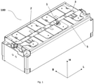
- orientation or positional relationship indicated by such terms as “front, rear, up, down, left, right", “lateral, longitudinal, vertical, horizontal”, and “top, bottom” is generally based on the orientation and position when the battery module in Fig. 1 is normally placed.
- Such terms are merely for the convenience of description of the present application and simplified description, rather than indicating or implying that the device or element referred to must be located in a certain orientation or must be constructed or operated in a certain orientation without a statement to the contrary, therefore, the terms cannot be understood as a limitation to the protection scope of the present application; and such orientation terms as “inner, outside” mean inner or outside relative to the contour of each part itself.
- Figs. 1-21 show one embodiment of a battery module of the present application. Please refer to Figs. 1-21 , the battery module 100 provided in the present application includes:
- the temperature sensor In the existing temperature collection solution of the top cover of a battery, the temperature sensor is generally arranged on a harness plate of the battery module, and the problems lie in that, on the one hand, a contact between the temperature sensor and the top cover is not so tight, and on the other hand, the solution is merely applicable to the battery module with a harness plate, but not applicable to the battery module with no harness plate.
- the bearing structure 13 is added, and the bearing structure 13 is configured to press, under the effect of a circuit board 3 and/or a bus bar 2, the temperature collection structure including the temperature sensor 11 to be abutted against the top cover 52 of the battery 5, then not only the temperature collection structure can be in closer contact with the top cover 52, thereby realizing a more accurate collection of the temperature of the battery module 100, but also the temperature collection solution of the top cover no longer relies on the harness plate, thereby effectively enlarging the application range of the temperature collection solution of the top cover, and expanding the application range of the temperature collection solution of the top cover from only the battery module with the harness plate to the battery module with no harness plate.
- the bearing structure 13 in order to enable the bearing structure 13 to press, under the effect of the bus bar 2, the temperature collection structure to be abutted against the top cover 22, the bearing structure 13 may be connected to the bus bar 2.
- the bus bar 2 can exert a pressing effect onto the temperature collection structure through the bearing structure 13, and the temperature collection structure can then be in closer contact with the top cover 52.
- the temperature collection structure can be further fixed reliably, which is beneficial for improving the stability of contact between the temperature collection structure and the top cover 52, and is further beneficial for improving accuracy of results of temperature collection of the top cover.
- the bearing structure 13 can be connected with the bus bar 2 in a plurality of manners.
- the bearing structure 13 can be in threaded connection with the bus bar 2; for another example, in some other embodiments, the bearing structure 13 can be clamped with the bus bar 2.
- a limiting groove 13a may be arranged on the bearing structure 13, and the temperature sensor 11 may be arranged in the limiting groove 13a.
- a bearing function of the bearing structure 13 to the temperature sensor 11 can be realized, but also a limiting function to the temperature sensor 11 can be realized by the limiting groove 13a, such that the temperature collection structure can be more stably kept at an anticipated position at which the temperature collection structure is in contact with the top cover 52, so as to prevent the risk of incapability in collecting temperature of the top cover when the temperature sensor 11 is displaced under such working conditions as shock or vibration.
- the bearing structure 13 includes a bearing body 131 and an elastic sheet 133, the temperature sensor 11 and the elastic sheet 133 are both arranged on the bearing body 131, and the elastic sheet 133 is arranged above the temperature sensor 11. Based on this, the bearing structure 13 can not only transfer the pressing effect of the circuit board 3 and/or the bus bar 2, meanwhile the bearing structure 13 itself can also exert a pressing effect onto the temperature sensor 11 through the elastic sheet 133 , therefore, the temperature collection structure can be in more reliable contact with the top cover 52, thereby realizing a more accurate temperature collection process.
- the elastic sheet 133 may further be configured to realize electrical connection between the temperature sensor 11 and the circuit board 3, then a part which electrically connects the temperature sensor 11 and the circuit board 3 does not need to be set additionally, therefore, the structure is simple and compact.
- the number of the elastic sheets 133 may be set to be two, the two elastic sheets 133 are respectively electrically connected with a positive electrode and a negative electrode of the temperature sensor 11, and are both electrically connected with the circuit board 3, so as to realize electrical connection between the temperature sensor 11 and the circuit board 3, such that temperature signals collected by the temperature sensor 11 can be smoothly transferred to the circuit board 3, then the circuit board 3 can further transfer the temperature signals to the battery management system (BMS), to serve as a basis for the BMS to control battery security, charging and discharging strategy of the battery, and traffic safety, etc.
- BMS battery management system
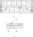
- the temperature collection structure may further include a thermal conducting pad 12 while including a temperature sensor 11, and the thermal conducting pad 12 is arranged between the temperature sensor 11 and the top cover 52. Under this condition, the temperature sensor 11 is in contact with the top cover 52 through the thermal conducting pad 12, and the thermal conducting pad 12 can transfer the temperature of the top cover 52 to the temperature sensor 11. Since the thermal conducting pad 12 has a certain deformability, when the bearing structure 13 exerts a pressing effect onto the temperature collection structure, the thermal conducting pad 12 can deform favorably, to realize closer contact with the top cover 52.
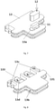
- the battery module 100 includes a battery 5, a bus bar 2, a circuit board 3 and a temperature collection unit 1.
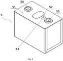
- each battery 5 includes a top cover 52, a top patch 51, a positive electrode terminal 54 and a negative electrode terminal 55.
- the top patch 51 is affixed to an upper surface of the top cover 52, to shield the top cover 52, thereby on the one hand playing an effect of insulation to prevent short circuit between the top cover 52 and an external circuit, and on the other hand playing a role of protection to prevent the top cover 52 from being scratched; and the positive electrode terminal 54 and the negative electrode terminal 55 extend upwards to the outside of the top patch 51 to be electrically connected with the external circuit.
- the top patch 51 is provided with a sampling hole 53, and the sampling hole 53 is a through hole, therefore, the sampling hole 53 can remove shielding of a corresponding part of the top patch 51 to the top cover 52, such that the corresponding part of the top cover 52 is exposed, that is, the sampling hole 53 can expose the top cover 52, in this way, the temperature collection structure of the temperature collection unit 1 can stretch into the sampling hole 53, and is in contact with the top cover 52 at the sampling hole 53, then realizing collection of the temperature of the top cover 52.
- the sampling hole 53 it's convenient for the temperature collection structure to be close to the top cover 52.
- the sampling hole 53 of the present embodiment is arranged between the positive electrode terminal 54 and the negative electrode terminal 55, and is more adjacent to the negative electrode terminal 55.
- a temperature at the negative electrode terminal 55 is closer to the internal temperature of the battery 1, therefore, in the present embodiment, the sampling hole 53 being set to be adjacent to the negative electrode terminal 55 is also beneficial for improving accuracy of temperature collection.
- the bus bar 2 (also known as Busbar or electrical connecting sheet) is configured to connect electrode terminals of adjacent batteries 5, to electrically connect adjacent batteries 5, and realize series and parallel connection of a plurality of batteries 5.
- the circuit board 3 above all the batteries 5 is internally provided with a circuit, and is configured to electrically connect the temperature sensor 11 and the battery management system (BMS). Based on this, the temperature signals collected by the temperature collection structure can be transferred to the BMS via the circuit board 3.
- BMS battery management system
- the circuit board 3 may be a PCB board (Printed Circuit Board) or a FPC board (Flexible Printed Circuit Board).
- the PCB board is high in rigidity and hardness, while the FPC board is high in flexibility and low in hardness.
- the circuit board 3 being an FPC board is taken as an example.
- the FPC board is also called a flexible circuit board, and is a printed circuit board which is manufactured with polyimide or polyester film as a base material and which has high reliability and excellent flexibility, and the FPC board is characterized by high wiring density, light weight, thin thickness and good bending.
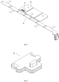
- the circuit board 3 is further provided with a metal sheet 4, and the circuit board 3 is electrically connected with the temperature sensor 11 through the metal sheet 4. In this way, the metal sheet 4 and the circuit board 3 are combined to form a circuit board assembly.
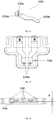
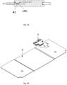
- the temperature collection unit 1 is configured to collect the temperature of the top cover 52. As shown in Fig. 1 , the battery module 100 only includes one temperature collection unit 1. Moreover, as shown in Fig. 6 and Fig. 7 , to realize a function of temperature collection, in the present embodiment, the temperature collection unit 1 includes a temperature collection structure which is provided with a temperature sensor 11 and a thermal conducting pad 12; meanwhile, to fix the temperature collection structure, and to realize sufficient contact between the temperature collection structure and the top cover 52, in the present embodiment, the temperature collection unit 1 further includes a bearing structure 13, and the bearing structure 13 is configured to bear the temperature collection structure and press the temperature collection structure to be abutted against the top cover 52.
- the temperature sensor 11 is configured to collect the temperature and transfer the temperature detection results to the circuit board 3.
- the temperature sensor 11 is NTC (Negative Temperature Coefficient), that is, a thermal resistor with negative temperature coefficient, and a resistance decreases exponentially along with a rise in temperature.
- NTC Negative Temperature Coefficient
- the temperature sensor 11 may also adopt other structural forms like a platinum thermistor.
- the temperature sensor 11 is not in direct contact with the top cover 52, but is in contact with the top cover 52 through the thermal conducting pad 12.
- the thermal conducting pad 12 is arranged between the temperature sensor 11 and the top cover 52, an upper surface of the thermal conducting pad 12 is in contact with a lower surface of the temperature sensor 11, and a lower surface of the thermal conducting pad 12 is in contact with the top cover 52, to transfer the temperature of the top cover 52 to the temperature sensor 11, and realize thermal conduction between the temperature sensor 11 and the top cover 52.
- the thermal conducting pad 12 may be connected with the temperature sensor 11 through such connecting manners as adhesive connection.
- the adhesive connection manner may be realized through coating thermal conductive adhesive between the thermal conducting pad 12 and the temperature sensor 11.
- the thermal conducting pad 12 is of high thermal conductivity coefficient, high thermal conducting efficiency, good compression performance and strong bearing strength, and can bear extrusion of the EOL (End of Life) of the module during expansion deformation and impact vibration. Therefore, when the temperature sensor 11 is in contact with the top cover 52 through the thermal conducting pad 12, not only a more efficient temperature collection process can be realized, but also the contact sufficiency between the temperature collection structure and the top cover 52 can be improved, which is especially dramatic when the bearing structure 13 exerts a pressing effect onto the temperature collection structure.
- the thermal conducting pad 12 is set in such a way that a thickness of the thermal conducting pad 12 in an original state (that is, in an uncompressed state) is greater than a distance between the lower surface of the temperature sensor 11 and the top cover 52, to better match with the bearing structure 13 and be closely abutted against the top cover 52.
- the battery module 100 of the present embodiment does not include a harness plate, therefore, the temperature sensor 11 can no longer be arranged on the harness plate as what is done in the prior art, and the temperature sensor 11 can no longer be fixed by the harness plate.
- the bearing structure 13 arranged in the present embodiment can effectively solve the problem.
- the bearing structure 13 bears the temperature collection structure and is connected with both the bus bar 2 and the circuit board 3, and the bearing structure 13 includes a bearing body 131 and two elastic sheets 133.
- the bearing body 131 provides an installation base for the temperature collection structure and the elastic sheet 133, and is connected with the bus bar 2, such that the connection between the bearing structure 13 and the bus bar 2 is realized, the temperature collection structure is fixed and limited, and the bearing structure 13 can press the temperature collection structure under the effect of the bus bar 2.
- a lower surface of the bearing body 131 is provided with a limiting groove 13a, and the temperature sensor 11 and the thermal conducting pad 12 are both arranged in the limiting groove 13a.
- the temperature collection structure is arranged on the bearing body 131, and the limiting groove 13a can play a certain limiting role on the temperature collection structure, to prevent unanticipated displacement of the temperature sensor 11 and the thermal conducting pad 12 under severe working conditions, which affects accuracy in temperature collection by affecting the contact between the temperature collection structure and the top cover 52.
- the limiting groove 13a of the present embodiment further plays a role of facilitating electrical connection between the elastic sheet 133 and the temperature sensor 11, which will be illustrated in more details below in combination with the setting characteristics of the elastic sheet 133.
- the bearing body 131 of the present embodiment is internally provided with an accommodating space, and the elastic sheets 133 are arranged in the accommodating space, that is, in the present embodiment, the elastic sheet 133 is arranged inside the bearing body 131. Based on this, the bearing body 131 can limit and fix the elastic sheet 133, and prevent the elastic sheet 133 from being damaged or reducing damage to the elastic sheet 133, meanwhile, the bearing body 131 can further exert a certain pressure onto the elastic sheet 133, which is beneficial for enhancing the pressing effect of the elastic sheet 133 on the temperature sensor 11.
- the bearing body 131 is provided with a first clamping structure
- the bus bar 2 is provided with a second clamping structure configured to be clamped with the first clamping structure, in this way, based on the match between the first clamping structure and the second clamping structure, the bearing body 131 is clamped with the bus bar 2.
- the bearing body 131 is clamped onto the bus bar 2, such that the temperature collection unit 1 is entirely fixed by the bus bar 2, moreover, assembly is convenient, and fixation is reliable, displacement does not occur easily due to an external force, thereby improving reliability and stability of the contact between the temperature collection structure and the top cover 52. Meanwhile, the bus bar 2 can exert a pressing effect onto the temperature collection structure through the clamped bearing body 131, such that the temperature sensor 11 can be in closer contact with the top cover 52 through the thermal conducting pad 12, to improve the accuracy in temperature collection.
- the first clamping structure includes a clamping groove 13b and a buckle 13c
- the second clamping structure includes an installation groove 21 and a limiting opening 22.
- the clamping groove 13b is matched with the installation groove 21, to limit up and down as well as left and right displacements of the bearing body 131; and the buckle 13c is matched with the limiting opening 22, to limit the front and rear displacements of the bearing body 31.
- a shape of the installation groove 21 is matched with a shape of the bearing body 131, the bearing body 131 is accommodated in the installation groove 21, and the wall of the installation groove 21 is inserted into the clamping groove 13b, meanwhile, the limiting opening 22 is arranged on the wall of the installation groove 21, and the buckle 13c is clamped into the limiting opening 22.
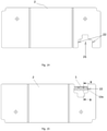
- the installation groove 21 and the bearing body 131 are generally shaped as a Chinese character "convex" along their assembly direction (as shown by an arrow in Fig. 20 , which is also the direction from the circuit board 3 to the bus bar 2), in other words, the installation groove 21 and the bearing body 131 both include two rectangles with different sizes which are arranged along the assembly direction of the installation groove 21 and the bearing body 131 and are connected with each other, wherein the rectangle with a larger area is more adjacent to the circuit board 3 than the rectangle with a smaller area, that is, the area of the rectangle far away from the circuit board 3 is smaller than the area of the other rectangle adjacent to the circuit board 3.
- the clamping groove 13b is arranged between an upper surface and the lower surface of the bearing body 131, and is arranged at an edge of the bearing body 131; while the buckle 13c is arranged at a tail end (that is, the end adjacent to the circuit board 3) of the bearing body 131, and two buckles 13c are arranged at two sides, along a length direction of the battery module 100, of the bearing body 131, correspondingly, as shown in Fig. 14 , the number of the limiting openings 22 is also two, and the two limiting openings 22 are respectively arranged at two opposite side walls, along the length direction of the battery module 100, of the installation groove 21.
- the bearing body 131 of the present embodiment may be a plastic piece, and may be processed through an injection molding process. Since the bearing body 131 is a plastic piece, the bearing body 131 and the bus bar 2 are insulated from each other. It should be understood that, in other embodiments, the bearing body 131 may be made from insulating materials other than plastics.
- the elastic sheet 133 is configured to electrically connect the temperature sensor 11 and the circuit board 3, and exert a pressing effect onto the temperature sensor 11, such that the bearing structure 13 itself also has a certain pushing and pressing effect on the temperature collection structure.
- the elastic sheet 133 as a metal elastic sheet is arranged inside the bearing body 131, and is located above the temperature sensor 11, moreover, the elastic sheet 133 of the present embodiment is provided with a first end 133a and a second end 133b which are opposite to each other, the first end 133a is electrically connected with the circuit board 3, and the second end 133b is electrically connected with the temperature sensor 11.
- the elastic sheet 133 can realize electrical connection between the temperature sensor 11 and the circuit board 3, such that the temperature signals detected by the temperature sensor 11 can be transferred to the circuit board 3 via the elastic sheet 133 and the metal sheet 4, thereby further making it easier for the battery management system to control safety and charging and discharging of the battery based on the detected temperature signals.
- the first end 133a realizes electrical connection with the circuit board 3 through connection with the metal sheet 4. It can be known in combination with Fig. 11 , Fig. 18 and Fig. 19 that, in the present embodiment, the first end 133a is provided with a protruding part 133c, the metal sheet 4 is provided with a concave part 41 matched with the convex part 133c, and the convex part 133c is buckled with the concave part 41. With the match between the convex part 133c and the concave part 41, the first end 133a is clamped with the metal sheet 4, assembly is simple, connection is reliable, and receding of the metal sheet 4 can be prevented.
- the positions of the convex part 133c and the concave part 41 may be interchanged, that is, the convex part 133c may be arranged on the metal sheet 4, and the concave part 41 may be arranged on the first end 133a, in fact, as long as one of the convex part 133c and the concave part 41is arranged on the first end 133a, and the other one of the convex part 133c and the concave part 41 is arranged on the metal sheet 4, the clamping between the first end 133a and the metal sheet 4 can be realized.
- the first end 133a is concave downwards and is arc-shaped, and the metal sheet 4 is inserted between a lower surface of the first end 133a and the bearing body 131. Based on this, the elastic sheet 133 can effectively elastically press the metal sheet 4, which is beneficial for realizing closer contact and more reliable connection between the metal sheet 4 and the first end 133a.
- a gap h exists between the lower surface of the first end 133a and the bearing body 131, and the gap h provides a space for inserting and pulling the metal sheet 4.
- the gap h may be set to be smaller than or equal to a thickness of the metal sheet 4, so as to enhance the elastic pression effect of the elastic sheet 133 on the metal sheet 4, thereby more effectively maintaining a good contact between the elastic sheet 133 and the metal sheet 4.
- the first end 133a which is concave downwards and arc-shaped and the convex part 133c arranged on the first end 133a may be formed by stamping.
- an opening 13d for exposing the first end 133a is disposed on the upper surface of the bearing body 131 of the present embodiment, which not only facilitates deformation of the elastic sheet 133, thereby being beneficial for exerting a pressing effect by the elastic sheet 133 onto the temperature sensor 11, meanwhile, as shown in Fig. 13 , a side wall of the opening 13a (marked as an opening side wall 13f in Fig. 13 ) and a bottom wall of the opening 13a (marked as an opening bottom wall 13e in Fig.
- the setting of the opening 13a also facilitates insertion of the metal sheet 4.
- the opening 13a is arranged corresponding to the elastic sheet 133, and two elastic sheets 133 are arranged in the present embodiment, therefore, the bearing body 131 is also correspondingly provided with two openings 13a.
- the second end 133b is electrically connected with the temperature sensor 11 through welding with the temperature sensor 11.
- the second ends 133b of the two elastic sheets 133 are respectively welded with the positive electrode and the negative electrode of the temperature sensor 11, so as to be respectively electrically connected with the positive electrode and the negative electrode of the temperature sensor 11. Specifically, as shown in Fig.
- the above-mentioned limiting groove 13a arranged on the lower surface of the bearing body 131 is arranged below the second ends 133b of the two elastic sheets 133, and the bearing body 131 exposes the two second ends 133b, to realizing exposure of the two second ends 133b, thereby facilitating contact between the two second ends 133b and the temperature sensor 11, and further facilitating the welding between the two second ends 133b and the temperature sensor 11; meanwhile, it can be known from Fig. 11 and Fig. 12 that, in the present embodiment, the second end 133b is flat, such that the second end 133b can be in more sufficient contact with the temperature sensor 11, thereby being beneficial for realizing more reliable welding between the second end 133b and the temperature sensor 11.
- the temperature sensor 11 is placed in the limiting groove 13a arranged on the bearing body 131, and the positive electrode and the negative electrode of the temperature sensor 11 are welded to the second ends 133b of the two elastic sheets 133, and then the thermal conducting pad 12 is pasted to the lower surface of the temperature sensor 11 to form a temperature collection unit 1.
- the temperature collection unit 1 is inserted into the installation groove 21 of the bus bar 2 according to the direction shown by the horizontal arrow in the figure, such that the wall of the installation groove 21 is clamped into the clamping groove 13b on the bearing body 131, and the buckle 13c on the bearing body 131 is clamped into the limiting opening 22 on the wall of the installation groove 21, thereby realizing fixation between the temperature collection unit 1 and the bus bar 2.
- the sampling assembly is assembled to a semi-finished product of the battery module 100, and the bus bar 2 is welded onto the electrode terminal of the battery 5, to realize assembly of the sampling assembly and the semi-finished product of the battery module 100, and a housing can be further added subsequently to form a battery module 100.
- the bus bar 2 when the bus bar 2 is welded onto the electrode terminal of the battery 5, the bus bar 2 can drive the bearing body 131 to press the thermal conducting pad 12 with the thickness being greater than the distance between the temperature sensor 11 and the top cover 52, such that the thermal conducting pad 12 is in close fit with the top cover 52, to form interference contact as shown in Fig. 3 .
- the bearing structure 13 can press the temperature collection structure towards the direction adjacent to the top cover 52 under the effect of the bus bar 2, as this can improve contact tightness and contact reliability between the top cover 52 and the temperature collection structure, the accuracy in temperature collection is higher then.
- the contact tightness and the long-term contact reliability between the temperature collection structure and the top cover 52 are both improved, even under such severe working conditions as shock and vibration, the temperature collection structure can still be in favorable contact with the top cover 52, therefore, a more accurate and reliable temperature collection process of the top cover can be realized.
- a temperature collection path is as follows: the top cover 52-the thermal conducting pad 12-the temperature sensor 11-the elastic sheet 133-the metal sheet 4-the circuit board 3, which is a short thermal conducting path, with high temperature collection accuracy, and fast response speed.
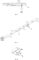
- the number of the temperature collection units 1 may also be two or more, such that the battery module 100 can have at least two temperature sampling points, thereby temperature collection of at least two sampling points being realized.
- each temperature collection unit 1 is arranged on the batteries 5 at different positions along the length direction of the battery module 100.
- two batteries 5 at edges at two sides of the battery module 100 and the battery 5 in the middle position of the battery module 100 may be respectively provided with one temperature collection unit 1.
- the temperature of the batteries 5 at two sides is generally low, and the temperature of the battery 5 in the middle position is high, therefore, temperature collection units 1 arranged at these three points can more accurately collect the temperature of the entire battery module 100.
- Embodiments of the present application further provide a device including the battery module described above, and the battery module is configured to provide electric energy.
- the device may be vehicles or energy-storage devices.
Landscapes
- Chemical & Material Sciences (AREA)
- Chemical Kinetics & Catalysis (AREA)
- Electrochemistry (AREA)
- General Chemical & Material Sciences (AREA)
- Engineering & Computer Science (AREA)
- Manufacturing & Machinery (AREA)
- Physics & Mathematics (AREA)
- General Physics & Mathematics (AREA)
- Battery Mounting, Suspending (AREA)
- Secondary Cells (AREA)
- Connection Of Batteries Or Terminals (AREA)
Applications Claiming Priority (2)
| Application Number | Priority Date | Filing Date | Title |
|---|---|---|---|
| CN201910575261.9A CN112151897B (zh) | 2019-06-28 | 2019-06-28 | 电池模组 |
| PCT/CN2020/092179 WO2020259173A1 (zh) | 2019-06-28 | 2020-05-25 | 电池模组及装置 |
Publications (4)
| Publication Number | Publication Date |
|---|---|
| EP3952004A1 true EP3952004A1 (de) | 2022-02-09 |
| EP3952004A4 EP3952004A4 (de) | 2022-07-13 |
| EP3952004C0 EP3952004C0 (de) | 2024-12-04 |
| EP3952004B1 EP3952004B1 (de) | 2024-12-04 |
Family
ID=73869339
Family Applications (1)
| Application Number | Title | Priority Date | Filing Date |
|---|---|---|---|
| EP20832295.8A Active EP3952004B1 (de) | 2019-06-28 | 2020-05-25 | Batteriemodul und vorrichtung |
Country Status (5)
| Country | Link |
|---|---|
| US (1) | US20220059882A1 (de) |
| EP (1) | EP3952004B1 (de) |
| CN (1) | CN112151897B (de) |
| HU (1) | HUE070211T2 (de) |
| WO (1) | WO2020259173A1 (de) |
Cited By (2)
| Publication number | Priority date | Publication date | Assignee | Title |
|---|---|---|---|---|
| EP4203139A1 (de) * | 2021-12-21 | 2023-06-28 | CALB Co., Ltd. | Batterievorrichtung |
| WO2024145591A1 (en) * | 2022-12-29 | 2024-07-04 | Cps Technology Holdings Llc | Battery cell temperature measurement system |
Families Citing this family (3)
| Publication number | Priority date | Publication date | Assignee | Title |
|---|---|---|---|---|
| CN217134619U (zh) * | 2022-04-11 | 2022-08-05 | 宁德时代新能源科技股份有限公司 | 防撕裂采样结构、电池及用电装置 |
| KR20240175621A (ko) * | 2023-06-13 | 2024-12-20 | 삼성에스디아이 주식회사 | 이차 전지 모듈 |
| CN117175151B (zh) * | 2023-11-02 | 2024-02-02 | 深圳海辰储能科技有限公司 | 用于电池模组的集成板、电池模组、储能设备及用电系统 |
Family Cites Families (22)
| Publication number | Priority date | Publication date | Assignee | Title |
|---|---|---|---|---|
| US8802275B2 (en) * | 2012-02-23 | 2014-08-12 | Samsung Sdi Co., Ltd. | Battery module |
| KR101925934B1 (ko) * | 2012-09-06 | 2018-12-06 | 삼성에스디아이 주식회사 | 배터리 팩 |
| KR102045528B1 (ko) * | 2013-02-14 | 2019-11-15 | 에스케이이노베이션 주식회사 | 배터리 모듈 |
| KR101720614B1 (ko) * | 2013-08-30 | 2017-03-28 | 삼성에스디아이 주식회사 | 배터리 팩 |
| KR101708365B1 (ko) * | 2013-09-13 | 2017-02-20 | 삼성에스디아이 주식회사 | 배터리 팩 |
| CN203503754U (zh) * | 2013-09-26 | 2014-03-26 | 中航锂电(洛阳)有限公司 | 锂离子动力电池盖板组件及使用该组件的锂离子动力电池 |
| CN204243121U (zh) * | 2014-11-05 | 2015-04-01 | 宁德时代新能源科技有限公司 | 一种连接条 |
| KR101678529B1 (ko) * | 2014-11-28 | 2016-11-22 | 삼성에스디아이 주식회사 | 접속 부재를 지지하기 위한 돌출부를 포함하는 이차전지 |
| KR20160085621A (ko) * | 2015-01-08 | 2016-07-18 | 삼성에스디아이 주식회사 | 이차전지 |
| US10573938B2 (en) * | 2015-06-25 | 2020-02-25 | Te Connectivity Corporation | Battery module with a temperature monitoring assembly |
| CN107403889B (zh) * | 2016-05-20 | 2020-06-30 | 莫列斯有限公司 | 电池连接模块 |
| CN205960151U (zh) * | 2016-07-29 | 2017-02-15 | 惠州市蓝微新源技术有限公司 | 温度采集结构及其温度采集组件 |
| CN205985249U (zh) * | 2016-08-11 | 2017-02-22 | 广州小鹏汽车科技有限公司 | 一种电动汽车电池模组温度探测结构 |
| EP3316338B1 (de) * | 2016-10-26 | 2018-10-24 | Samsung SDI Co., Ltd. | Batteriemodul mit einem ansatz für ein temperaturempfindliches element |
| EP3346524A1 (de) * | 2017-01-09 | 2018-07-11 | Samsung SDI Co., Ltd | Batteriemodul mit thermoelementeinheit |
| JP6675352B2 (ja) * | 2017-05-26 | 2020-04-01 | 矢崎総業株式会社 | バスバモジュール及び電源装置 |
| CN207183457U (zh) * | 2017-07-27 | 2018-04-03 | 宁德时代新能源科技股份有限公司 | 电池模组 |
| CN207116634U (zh) * | 2017-09-06 | 2018-03-16 | 宁德时代新能源科技股份有限公司 | 电池模组 |
| CN207558994U (zh) * | 2017-11-29 | 2018-06-29 | 长城汽车股份有限公司 | 电池模组组件和电池包 |
| CN207779574U (zh) * | 2018-01-31 | 2018-08-28 | 长城汽车股份有限公司 | 用于电池的温感器安装组件及电池 |
| CN207884968U (zh) * | 2018-03-13 | 2018-09-18 | 宁德时代新能源科技股份有限公司 | 一种柔性电路板及电池模组 |
| CN109148993A (zh) * | 2018-08-15 | 2019-01-04 | 北京海博思创科技有限公司 | 电池装置及新能源汽车 |
-
2019
- 2019-06-28 CN CN201910575261.9A patent/CN112151897B/zh active Active
-
2020
- 2020-05-25 WO PCT/CN2020/092179 patent/WO2020259173A1/zh not_active Ceased
- 2020-05-25 EP EP20832295.8A patent/EP3952004B1/de active Active
- 2020-05-25 HU HUE20832295A patent/HUE070211T2/hu unknown
-
2021
- 2021-11-05 US US17/520,010 patent/US20220059882A1/en active Pending
Cited By (2)
| Publication number | Priority date | Publication date | Assignee | Title |
|---|---|---|---|---|
| EP4203139A1 (de) * | 2021-12-21 | 2023-06-28 | CALB Co., Ltd. | Batterievorrichtung |
| WO2024145591A1 (en) * | 2022-12-29 | 2024-07-04 | Cps Technology Holdings Llc | Battery cell temperature measurement system |
Also Published As
| Publication number | Publication date |
|---|---|
| CN112151897B (zh) | 2022-03-29 |
| EP3952004A4 (de) | 2022-07-13 |
| US20220059882A1 (en) | 2022-02-24 |
| CN112151897A (zh) | 2020-12-29 |
| WO2020259173A1 (zh) | 2020-12-30 |
| EP3952004C0 (de) | 2024-12-04 |
| HUE070211T2 (hu) | 2025-05-28 |
| EP3952004B1 (de) | 2024-12-04 |
Similar Documents
| Publication | Publication Date | Title |
|---|---|---|
| EP3952004B1 (de) | Batteriemodul und vorrichtung | |
| CN112151703B (zh) | 电池模组 | |
| EP3734692B1 (de) | Batteriemodul und batteriepack | |
| CN201262963Y (zh) | 电池装置 | |
| US7589493B2 (en) | Charger | |
| EP3828986A1 (de) | Zur ermöglichung der genauen temperaturmessung strukturiertes batteriemodul und batteriesatz und kraftfahrzeug damit | |
| CN111653708B (zh) | 一种汇流排及电池模组 | |
| EP2405507A1 (de) | Wiederaufladbare Batterie | |
| CN112151894B (zh) | 电池模组 | |
| EP2645450A1 (de) | Zuverlässige und effiziente Verbindung für Batterien | |
| CN209822826U (zh) | 一种电池模组的采样装置及电池模组 | |
| CN101167198B (zh) | 电池部件 | |
| CN217641690U (zh) | 多极耳电芯及单体电池 | |
| CN220138403U (zh) | 一种电池模块和电池包 | |
| CN114649597B (zh) | 蓄电模块 | |
| US7845991B2 (en) | Apparatus for the electrical connection of cell arresters | |
| CN222620075U (zh) | 电芯温度采集结构、电池模组及动力电池 | |
| EP4513617A2 (de) | Batteriemodul, batteriepack und elektrische vorrichtung | |
| JP2010192310A (ja) | 電池モジュール | |
| CN214957037U (zh) | 电池模组、电池包及车辆 | |
| EP4459740A1 (de) | Batteriemodul | |
| CN223527346U (zh) | Ccs组件和电池模组 | |
| CN119315138B (zh) | 集成式电池包安全检测装置及其加工工艺 | |
| CN216872963U (zh) | 一种汽车电动窗马达壳体结构及汽车电动窗马达 | |
| CN215644637U (zh) | 电池模组和具有其的电池包 |
Legal Events
| Date | Code | Title | Description |
|---|---|---|---|
| STAA | Information on the status of an ep patent application or granted ep patent |
Free format text: STATUS: THE INTERNATIONAL PUBLICATION HAS BEEN MADE |
|
| PUAI | Public reference made under article 153(3) epc to a published international application that has entered the european phase |
Free format text: ORIGINAL CODE: 0009012 |
|
| STAA | Information on the status of an ep patent application or granted ep patent |
Free format text: STATUS: REQUEST FOR EXAMINATION WAS MADE |
|
| 17P | Request for examination filed |
Effective date: 20211103 |
|
| AK | Designated contracting states |
Kind code of ref document: A1 Designated state(s): AL AT BE BG CH CY CZ DE DK EE ES FI FR GB GR HR HU IE IS IT LI LT LU LV MC MK MT NL NO PL PT RO RS SE SI SK SM TR |
|
| A4 | Supplementary search report drawn up and despatched |
Effective date: 20220609 |
|
| RIC1 | Information provided on ipc code assigned before grant |
Ipc: H01M 50/569 20210101ALI20220603BHEP Ipc: H01M 50/15 20210101ALI20220603BHEP Ipc: H01M 50/209 20210101ALI20220603BHEP Ipc: H01M 50/284 20210101ALI20220603BHEP Ipc: H01M 50/502 20210101ALI20220603BHEP Ipc: H01M 10/48 20060101AFI20220603BHEP |
|
| DAV | Request for validation of the european patent (deleted) | ||
| DAX | Request for extension of the european patent (deleted) | ||
| STAA | Information on the status of an ep patent application or granted ep patent |
Free format text: STATUS: EXAMINATION IS IN PROGRESS |
|
| 17Q | First examination report despatched |
Effective date: 20221117 |
|
| GRAP | Despatch of communication of intention to grant a patent |
Free format text: ORIGINAL CODE: EPIDOSNIGR1 |
|
| STAA | Information on the status of an ep patent application or granted ep patent |
Free format text: STATUS: GRANT OF PATENT IS INTENDED |
|
| RAP1 | Party data changed (applicant data changed or rights of an application transferred) |
Owner name: CONTEMPORARY AMPEREX TECHNOLOGY(HONG KONG) LIMITED |
|
| INTG | Intention to grant announced |
Effective date: 20240911 |
|
| GRAS | Grant fee paid |
Free format text: ORIGINAL CODE: EPIDOSNIGR3 |
|
| GRAA | (expected) grant |
Free format text: ORIGINAL CODE: 0009210 |
|
| STAA | Information on the status of an ep patent application or granted ep patent |
Free format text: STATUS: THE PATENT HAS BEEN GRANTED |
|
| AK | Designated contracting states |
Kind code of ref document: B1 Designated state(s): AL AT BE BG CH CY CZ DE DK EE ES FI FR GB GR HR HU IE IS IT LI LT LU LV MC MK MT NL NO PL PT RO RS SE SI SK SM TR |
|
| REG | Reference to a national code |
Ref country code: CH Ref legal event code: EP |
|
| REG | Reference to a national code |
Ref country code: DE Ref legal event code: R096 Ref document number: 602020042660 Country of ref document: DE |
|
| REG | Reference to a national code |
Ref country code: IE Ref legal event code: FG4D |
|
| U01 | Request for unitary effect filed |
Effective date: 20250102 |
|
| U07 | Unitary effect registered |
Designated state(s): AT BE BG DE DK EE FI FR IT LT LU LV MT NL PT RO SE SI Effective date: 20250114 |
|
| PG25 | Lapsed in a contracting state [announced via postgrant information from national office to epo] |
Ref country code: HR Free format text: LAPSE BECAUSE OF FAILURE TO SUBMIT A TRANSLATION OF THE DESCRIPTION OR TO PAY THE FEE WITHIN THE PRESCRIBED TIME-LIMIT Effective date: 20241204 |
|
| PG25 | Lapsed in a contracting state [announced via postgrant information from national office to epo] |
Ref country code: ES Free format text: LAPSE BECAUSE OF FAILURE TO SUBMIT A TRANSLATION OF THE DESCRIPTION OR TO PAY THE FEE WITHIN THE PRESCRIBED TIME-LIMIT Effective date: 20241204 |
|
| PG25 | Lapsed in a contracting state [announced via postgrant information from national office to epo] |
Ref country code: NO Free format text: LAPSE BECAUSE OF FAILURE TO SUBMIT A TRANSLATION OF THE DESCRIPTION OR TO PAY THE FEE WITHIN THE PRESCRIBED TIME-LIMIT Effective date: 20250304 |
|
| PG25 | Lapsed in a contracting state [announced via postgrant information from national office to epo] |
Ref country code: GR Free format text: LAPSE BECAUSE OF FAILURE TO SUBMIT A TRANSLATION OF THE DESCRIPTION OR TO PAY THE FEE WITHIN THE PRESCRIBED TIME-LIMIT Effective date: 20250305 |
|
| PG25 | Lapsed in a contracting state [announced via postgrant information from national office to epo] |
Ref country code: RS Free format text: LAPSE BECAUSE OF FAILURE TO SUBMIT A TRANSLATION OF THE DESCRIPTION OR TO PAY THE FEE WITHIN THE PRESCRIBED TIME-LIMIT Effective date: 20250304 |
|
| REG | Reference to a national code |
Ref country code: HU Ref legal event code: AG4A Ref document number: E070211 Country of ref document: HU |
|
| U20 | Renewal fee for the european patent with unitary effect paid |
Year of fee payment: 6 Effective date: 20250522 |
|
| PG25 | Lapsed in a contracting state [announced via postgrant information from national office to epo] |
Ref country code: SM Free format text: LAPSE BECAUSE OF FAILURE TO SUBMIT A TRANSLATION OF THE DESCRIPTION OR TO PAY THE FEE WITHIN THE PRESCRIBED TIME-LIMIT Effective date: 20241204 |
|
| PG25 | Lapsed in a contracting state [announced via postgrant information from national office to epo] |
Ref country code: PL Free format text: LAPSE BECAUSE OF FAILURE TO SUBMIT A TRANSLATION OF THE DESCRIPTION OR TO PAY THE FEE WITHIN THE PRESCRIBED TIME-LIMIT Effective date: 20241204 |
|
| PGFP | Annual fee paid to national office [announced via postgrant information from national office to epo] |
Ref country code: GB Payment date: 20250519 Year of fee payment: 6 |
|
| PG25 | Lapsed in a contracting state [announced via postgrant information from national office to epo] |
Ref country code: IS Free format text: LAPSE BECAUSE OF FAILURE TO SUBMIT A TRANSLATION OF THE DESCRIPTION OR TO PAY THE FEE WITHIN THE PRESCRIBED TIME-LIMIT Effective date: 20250404 |
|
| PGFP | Annual fee paid to national office [announced via postgrant information from national office to epo] |
Ref country code: HU Payment date: 20250430 Year of fee payment: 6 |
|
| PG25 | Lapsed in a contracting state [announced via postgrant information from national office to epo] |
Ref country code: SK Free format text: LAPSE BECAUSE OF FAILURE TO SUBMIT A TRANSLATION OF THE DESCRIPTION OR TO PAY THE FEE WITHIN THE PRESCRIBED TIME-LIMIT Effective date: 20241204 |
|
| PG25 | Lapsed in a contracting state [announced via postgrant information from national office to epo] |
Ref country code: CZ Free format text: LAPSE BECAUSE OF FAILURE TO SUBMIT A TRANSLATION OF THE DESCRIPTION OR TO PAY THE FEE WITHIN THE PRESCRIBED TIME-LIMIT Effective date: 20241204 |
|
| PLBE | No opposition filed within time limit |
Free format text: ORIGINAL CODE: 0009261 |
|
| STAA | Information on the status of an ep patent application or granted ep patent |
Free format text: STATUS: NO OPPOSITION FILED WITHIN TIME LIMIT |
|
| 26N | No opposition filed |
Effective date: 20250905 |