EP4459740A1 - Batteriemodul - Google Patents
Batteriemodul Download PDFInfo
- Publication number
- EP4459740A1 EP4459740A1 EP23907277.0A EP23907277A EP4459740A1 EP 4459740 A1 EP4459740 A1 EP 4459740A1 EP 23907277 A EP23907277 A EP 23907277A EP 4459740 A1 EP4459740 A1 EP 4459740A1
- Authority
- EP
- European Patent Office
- Prior art keywords
- fpcb
- battery module
- side wall
- module according
- present disclosure
- Prior art date
- Legal status (The legal status is an assumption and is not a legal conclusion. Google has not performed a legal analysis and makes no representation as to the accuracy of the status listed.)
- Pending
Links
Images


Classifications
-
- H—ELECTRICITY
- H01—ELECTRIC ELEMENTS
- H01M—PROCESSES OR MEANS, e.g. BATTERIES, FOR THE DIRECT CONVERSION OF CHEMICAL ENERGY INTO ELECTRICAL ENERGY
- H01M50/00—Constructional details or processes of manufacture of the non-active parts of electrochemical cells other than fuel cells, e.g. hybrid cells
- H01M50/20—Mountings; Secondary casings or frames; Racks, modules or packs; Suspension devices; Shock absorbers; Transport or carrying devices; Holders
- H01M50/284—Mountings; Secondary casings or frames; Racks, modules or packs; Suspension devices; Shock absorbers; Transport or carrying devices; Holders with incorporated circuit boards, e.g. printed circuit boards [PCB]
-
- H—ELECTRICITY
- H01—ELECTRIC ELEMENTS
- H01M—PROCESSES OR MEANS, e.g. BATTERIES, FOR THE DIRECT CONVERSION OF CHEMICAL ENERGY INTO ELECTRICAL ENERGY
- H01M10/00—Secondary cells; Manufacture thereof
- H01M10/42—Methods or arrangements for servicing or maintenance of secondary cells or secondary half-cells
- H01M10/48—Accumulators combined with arrangements for measuring, testing or indicating the condition of cells, e.g. the level or density of the electrolyte
- H01M10/482—Accumulators combined with arrangements for measuring, testing or indicating the condition of cells, e.g. the level or density of the electrolyte for several batteries or cells simultaneously or sequentially
-
- H—ELECTRICITY
- H01—ELECTRIC ELEMENTS
- H01M—PROCESSES OR MEANS, e.g. BATTERIES, FOR THE DIRECT CONVERSION OF CHEMICAL ENERGY INTO ELECTRICAL ENERGY
- H01M10/00—Secondary cells; Manufacture thereof
- H01M10/42—Methods or arrangements for servicing or maintenance of secondary cells or secondary half-cells
- H01M10/48—Accumulators combined with arrangements for measuring, testing or indicating the condition of cells, e.g. the level or density of the electrolyte
- H01M10/486—Accumulators combined with arrangements for measuring, testing or indicating the condition of cells, e.g. the level or density of the electrolyte for measuring temperature
-
- H—ELECTRICITY
- H01—ELECTRIC ELEMENTS
- H01M—PROCESSES OR MEANS, e.g. BATTERIES, FOR THE DIRECT CONVERSION OF CHEMICAL ENERGY INTO ELECTRICAL ENERGY
- H01M50/00—Constructional details or processes of manufacture of the non-active parts of electrochemical cells other than fuel cells, e.g. hybrid cells
- H01M50/20—Mountings; Secondary casings or frames; Racks, modules or packs; Suspension devices; Shock absorbers; Transport or carrying devices; Holders
- H01M50/204—Racks, modules or packs for multiple batteries or multiple cells
- H01M50/207—Racks, modules or packs for multiple batteries or multiple cells characterised by their shape
- H01M50/213—Racks, modules or packs for multiple batteries or multiple cells characterised by their shape adapted for cells having curved cross-section, e.g. round or elliptic
-
- H—ELECTRICITY
- H01—ELECTRIC ELEMENTS
- H01M—PROCESSES OR MEANS, e.g. BATTERIES, FOR THE DIRECT CONVERSION OF CHEMICAL ENERGY INTO ELECTRICAL ENERGY
- H01M50/00—Constructional details or processes of manufacture of the non-active parts of electrochemical cells other than fuel cells, e.g. hybrid cells
- H01M50/20—Mountings; Secondary casings or frames; Racks, modules or packs; Suspension devices; Shock absorbers; Transport or carrying devices; Holders
- H01M50/233—Mountings; Secondary casings or frames; Racks, modules or packs; Suspension devices; Shock absorbers; Transport or carrying devices; Holders characterised by physical properties of casings or racks, e.g. dimensions
- H01M50/238—Flexibility or foldability
-
- H—ELECTRICITY
- H01—ELECTRIC ELEMENTS
- H01M—PROCESSES OR MEANS, e.g. BATTERIES, FOR THE DIRECT CONVERSION OF CHEMICAL ENERGY INTO ELECTRICAL ENERGY
- H01M50/00—Constructional details or processes of manufacture of the non-active parts of electrochemical cells other than fuel cells, e.g. hybrid cells
- H01M50/50—Current conducting connections for cells or batteries
- H01M50/502—Interconnectors for connecting terminals of adjacent batteries; Interconnectors for connecting cells outside a battery casing
- H01M50/519—Interconnectors for connecting terminals of adjacent batteries; Interconnectors for connecting cells outside a battery casing comprising printed circuit boards [PCB]
-
- H—ELECTRICITY
- H01—ELECTRIC ELEMENTS
- H01M—PROCESSES OR MEANS, e.g. BATTERIES, FOR THE DIRECT CONVERSION OF CHEMICAL ENERGY INTO ELECTRICAL ENERGY
- H01M50/00—Constructional details or processes of manufacture of the non-active parts of electrochemical cells other than fuel cells, e.g. hybrid cells
- H01M50/20—Mountings; Secondary casings or frames; Racks, modules or packs; Suspension devices; Shock absorbers; Transport or carrying devices; Holders
- H01M50/249—Mountings; Secondary casings or frames; Racks, modules or packs; Suspension devices; Shock absorbers; Transport or carrying devices; Holders specially adapted for aircraft or vehicles, e.g. cars or trains
-
- Y—GENERAL TAGGING OF NEW TECHNOLOGICAL DEVELOPMENTS; GENERAL TAGGING OF CROSS-SECTIONAL TECHNOLOGIES SPANNING OVER SEVERAL SECTIONS OF THE IPC; TECHNICAL SUBJECTS COVERED BY FORMER USPC CROSS-REFERENCE ART COLLECTIONS [XRACs] AND DIGESTS
- Y02—TECHNOLOGIES OR APPLICATIONS FOR MITIGATION OR ADAPTATION AGAINST CLIMATE CHANGE
- Y02E—REDUCTION OF GREENHOUSE GAS [GHG] EMISSIONS, RELATED TO ENERGY GENERATION, TRANSMISSION OR DISTRIBUTION
- Y02E60/00—Enabling technologies; Technologies with a potential or indirect contribution to GHG emissions mitigation
- Y02E60/10—Energy storage using batteries
Definitions
- the present disclosure relates to a battery module.
- втори ⁇ ески ⁇ в ⁇ ное в ⁇ ное в ⁇ ное в ⁇ ество include nickel-cadmium batteries, nickel-hydrogen batteries, nickel-zinc batteries, lithium secondary batteries and so on, and among them, lithium secondary batteries have little or no memory effect, and thus they are gaining more attention than nickel-based secondary batteries for their advantages that recharging can be done whenever it is convenient, the self-discharge rate is very low and the energy density is high.
- nickel-based secondary batteries include nickel-cadmium batteries, nickel-hydrogen batteries, nickel-zinc batteries, lithium secondary batteries and so on, and among them, lithium secondary batteries have little or no memory effect, and thus they are gaining more attention than nickel-based secondary batteries for their advantages that recharging can be done whenever it is convenient, the self-discharge rate is very low and the energy density is high.
- lithium secondary batteries may be classified into cylindrical secondary batteries in which an electrode assembly is included in a metal can and pouch-type secondary batteries in which an electrode assembly is included in a pouch of an aluminum laminate sheet, according to the shape of an outer packaging.
- the present disclosure is designed to solve these and other problems.
- the present disclosure is directed to providing a battery module including a structure for improving assemblability of a flexible printed circuit board (FPCB) including a temperature sensor.
- FPCB flexible printed circuit board
- the present disclosure is further directed to providing a battery module including a structure for bringing a temperature sensor into close contact with a battery cell while preventing damage to the temperature sensor.
- a battery module includes a case including a base plate and a side wall protruding upwards from the base plate, and providing an internal space; a plurality of battery cells received in the case, and arranged along the side wall; a flexible printed circuit board (FPCB) disposed between any one of the plurality of battery cells and the side wall, and having a surface facing the side wall; and a temperature sensor disposed on the surface of the FPCB.
- FPCB flexible printed circuit board
- the battery module may further include a pad having a compression property between the FPCB and the side wall.
- the plurality of battery cells may have a cylindrical shape extending in a vertical direction, and a portion of the side wall facing the FPCB may have a curved surface along a side of the battery cell facing the FPCB.
- the pad may be attached to the surface of the FPCB.
- the pad may be made of polyurethane.
- the side wall may include a groove in which at least a portion of the pad is received.
- the pad may include an accommodation portion in which the temperature sensor is received.
- the pad may include a portion having a decreasing cross section as it goes downwards.
- the battery module may further include a main FPCB extending along the side wall, and the FPCB may extend and bend from the main FPCB.
- a battery pack according to an embodiment of the present disclosure includes the battery module according to the present disclosure.
- a vehicle according to an embodiment of the present disclosure includes the battery module according to the present disclosure.
- the battery module including the structure for improving assemblability of the flexible printed circuit board (FPCB) including the temperature sensor.
- FPCB flexible printed circuit board
- the battery module including the structure for bringing the temperature sensor into close contact with the battery cell while preventing damage to the temperature sensor.
- the present disclosure may have many other effects, and these effects will be described in each embodiment, or regarding effects that can be easily anticipated by those skilled in the art, the corresponding description is omitted.
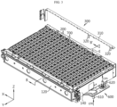
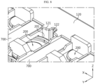
- FIG. 1 shows a battery module according to an embodiment of the present disclosure.
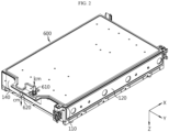
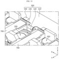
- FIG. 2 is a diagram of the battery module of FIG. 1 when viewed from a different direction.
- FIG. 3 is a partial exploded view of the battery module according to an embodiment of the present disclosure.
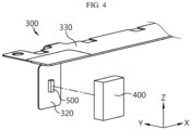
- FIG. 4 is an exploded view of a flexible printed circuit board (FPCB) 300 of the battery module according to an embodiment of the present disclosure.
- FIG. 5 is a diagram showing the FPCB 300 of the battery module according to an embodiment of the present disclosure.
- FIG. 6 is a cross-sectional view of FIG. 5 , taken along the line C-C'.
- the battery module according to an embodiment of the present disclosure may include a case 100, a plurality of battery cells 200, the FPCB 300 and a temperature sensor 500.
- the case 100 may have an internal space.
- the case 100 may include a base plate 110, a side wall 120, a front wall 130 and a rear wall 140.
- the base plate 110 may be a plate of a rectangular shape.
- the side wall 120 may protrude in +Z axis direction or upward direction from the base plate 110.
- the front wall 130 may protrude in +Z axis direction or upward direction from the base plate 110.
- the rear wall 140 may protrude in +Z axis direction or upward direction from the base plate 110.
- the front wall 130, the rear wall 140 and the side wall 120 may be integrally formed with or connected to one another.
- the case 100 may further include a top plate.
- the top plate may cover the internal space.
- the top plate may be integrally formed with or connected or coupled to the front wall 130, the rear wall 140 and the side wall 120.
- the plurality of battery cells 200 may be received in the case 100.
- the plurality of battery cells 200 may refer to secondary batteries.
- the plurality of battery cells 200 may be cylindrical battery cells 200. Alternatively, each of the plurality of battery cells 200 may have a cylindrical shape.
- the plurality of battery cells 200 may be arranged in column. Additionally, the plurality of battery cells 200 may be arranged along the lengthwise direction of the side wall 120, the front wall 130 or the rear wall 140.
- the FPCB 320 may be referred to as a sub FPCB 320.
- the sub FPCB 320 may have a surface facing the side wall 120. The other surface of the sub FPCB 320 may face a side of the battery cell 200.
- the sub FPCB 320 may include a plurality of sub FPCBs 320.
- the temperature sensor 500 may be disposed on one surface of the sub FPCB 320.
- the sub FPCB 320 may include a plurality of sub FPCBs 320, and the temperature sensor 500 may be disposed at each of the sub FPCBs 320.
- the sub FPCB 320 may include two sub FPCBs 320, and the temperature sensor 500 may be disposed at each of the two sub FPCBs 320.
- the temperature sensor 500 since the temperature sensor 500 is disposed at the sub FPCB 320, the temperature sensor 500 may come into close contact with the side 201 of the battery cell 200.
- the side 201 of the battery cell 200 has a curved surface, and the temperature sensor 500 is disposed at the sub FPCB 320, so the temperature sensor 500 may easily come into close contact with the curved surface.
- the battery module may include a heat sink 600.
- the heat sink 600 may be in the shape of rectangular plate.
- the heat sink 600 may come into contact with or be fixed, fastened or coupled to the lower surface of the base plate 110. Alternatively, the heat sink 600 may act as the base plate 110.
- the heat sink 600 may have an inlet port 610 and an outlet port 620.
- a cooling medium (cm) may enter the inlet port 610, pass through a flow path inside the heat sink 600 and exit the outlet port 620. In this instance, to stably control the battery module, it is necessary to measure the highest temperature in the plurality of battery cells 200.
- the plurality of temperature sensors 500 may be disposed at an expected location at which the highest temperature in the plurality of battery cells 200 will occur. Since the temperature of the cooling medium (cm) passing through the heat sink 600 continuously changes while the cooling medium (cm) is moving along the flow path, a temperature difference between the plurality of battery cells 200 may occur.
- the battery module may further include a main FPCB 310 extending along the side wall 120, and the sub FPCB 320 may extend and bend from the main FPCB 310.
- the main FPCB 310 and the sub FPCB 320 may be collectively referred to the FPCB 300.
- the main FPCB 310 and the sub FPCB 320 may be integrally formed with each other.
- the FPCB 300 may further include a connection portion 330 physically and electrically connecting the main FPCB 310 to the sub FPCB 320.
- sub FPCB 320 since the temperature sensor 500 is disposed at the sub FPCB 320, sub FPCB 320 may easily bend and be assembled or fastened to the battery module. Accordingly, it may be possible to improve assemblability and productivity of the battery module.
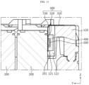
- the battery module may further include a pad 400 having a compression property between the sub FPCB 320 and the side wall 120.
- the pad 400 may be made of a material having the ability to be compressed under applied pressure and restore to its original shape after being compressed.
- the pad 400 may be fixed and compressed between the sub FPCB 320 and the side wall 120.
- the pad 400 may guide the sub FPCB 320 to form a curved surface.
- the pad 400 may bend the sub FPCB 320 to bring the sub FPCB 320 into close contact with the curved surface of the side 201 of the battery cell 200.
- the temperature sensor 500 may come into surface contact or close contact with the curved surface of the side 201 of the cell. Accordingly, it may be possible to improve accuracy of the temperature sensor 500 and accuracy in battery module control.
- the pad 400 of the battery module may be attached to one surface of the sub FPCB 320.
- the temperature sensor 500 may be disposed on one surface of the sub FPCB 320 and the pad 400 may be attached thereto.
- the pad 400 may be configured to maintain the compressibility of about 50% to prevent damage to the temperature sensor 500.
- the applied pressure to the temperature sensor 500 by the pad 400 may be lower than a limit pressure at which temperature sensor 500 normally operates.
- the temperature sensor 500 may come into close contact with the curved surface of the side 201 of the cell without damage caused by the pressure of the pad 400.
- the pad 400 of the battery module according to an embodiment of the present disclosure may be made of polyurethane.
- the temperature sensor 500 may come into surface contact or close contact with the curved surface of the side 201 of the cell. Accordingly, it may be possible to improve accuracy of the temperature sensor 500 and accuracy in battery module control.
- the pad 400 of the battery module may include an accommodation portion 410 in which the temperature sensor 500 is received.
- the temperature sensor 500 since the temperature sensor 500 is received in the accommodation portion 410, the temperature sensor 500 may not be subjected to pressure from the pad 400 when the pad 400 is compressed. Accordingly, the function of the temperature sensor 500 may be stably maintained.
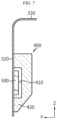
- FIG. 7 is a diagram showing a variation of the FPCB 300 of the battery module according to an embodiment of the present disclosure.
- the pad 400 of the battery module according to an embodiment of the present disclosure may include a portion having a decreasing cross section as it goes toward -Z axis direction or downward direction.
- the pad may include a downward sloping portion.
- the FPCB 300 may be easy to assemble or couple the FPCB 300.
- the FPCB 300 may be assembled or fastened by inserting or interposing it between the side wall 120 and the battery cell 200. Accordingly, since a portion of the pad 400 where the insertion starts has a small cross section, the FPCB 300 may be easily inserted or interposed between the side wall 120 and the battery cell 200.
- the battery module may include a plurality of busbars 700.
- Each of the plurality of busbars 700 may be electrically connected to the plurality of battery cells 200.
- the main FPCB 310 may have a plurality of terminals 340 arranged along the lengthwise direction. The plurality of terminals 340 may be electrically connected to the plurality of busbars 700, respectively.
- FIG. 8 is an enlarged view of section D in FIG. 3 .
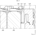
- FIG. 9 is a cross-sectional view of FIG. 3 , taken along the line B-B'.
- FIG. 10 is an enlarged view of section E in FIG. 1 .
- FIG. 11 is a cross-sectional view of FIG. 1 , taken along the line A-A'.
- the plurality of battery cells 200 of the battery module may have a cylindrical shape extending in the vertical direction, and a portion of the side wall 120 facing the sub FPCB 320 may have a curved surface along the side 201 of the battery cell 200 facing the sub FPCB 320.
- the side wall 120 may have the curved surface 121 having the curvature that is similar or substantially equal to the side 201 of the cylindrical battery cell 200.
- the side wall 120 may bend or guide the sub FPCB 320 to bring the sub FPCB 320 into surface contact or close contact with the side 201 of the cylindrical battery cell 200.
- the side wall 120 of the battery module may include a groove in which at least a portion of the pad 400 is received.
- the groove may be formed in the vertical direction or Z axis direction. At least the portion of the pad 400 may be compressed and received in the groove.
- the pressure applied to the temperature sensor 500 by the pad 400 may be mitigated. Accordingly, it may be possible to prevent damage to the temperature sensor 500, and improve safety in battery module control.
- a battery pack according to the present disclosure may include the battery module according to the present disclosure. Additionally, in addition to the battery module according to the present disclosure, the battery pack according to the present disclosure may further include a variety of other components, for example, components of the battery pack known at the time that the application was filed, such as a battery management system (BMS) or the busbar, the pack case 100, a relay, a current sensor and so on.
- BMS battery management system
- the busbar such as a battery management system (BMS) or the busbar, the pack case 100, a relay, a current sensor and so on.
- a vehicle according to the present disclosure may include the battery module according to the present disclosure.
- the battery module according to the present disclosure may be used in a vehicle such as an electric vehicle or a hybrid electric vehicle. Additionally, in addition to the battery module, the vehicle according to the present disclosure may further include any other components included in the vehicle, for example, a vehicle body, a motor, a control device such as an electronic control unit (ECU) and so on.
- ECU electronice control unit
Landscapes
- Chemical & Material Sciences (AREA)
- Chemical Kinetics & Catalysis (AREA)
- Electrochemistry (AREA)
- General Chemical & Material Sciences (AREA)
- Engineering & Computer Science (AREA)
- Manufacturing & Machinery (AREA)
- Battery Mounting, Suspending (AREA)
- Secondary Cells (AREA)
Applications Claiming Priority (3)
| Application Number | Priority Date | Filing Date | Title |
|---|---|---|---|
| KR20220183528 | 2022-12-23 | ||
| KR1020230077754A KR20240101320A (ko) | 2022-12-23 | 2023-06-16 | 배터리 모듈 |
| PCT/KR2023/012126 WO2024135987A1 (ko) | 2022-12-23 | 2023-08-16 | 배터리 모듈 |
Publications (2)
| Publication Number | Publication Date |
|---|---|
| EP4459740A1 true EP4459740A1 (de) | 2024-11-06 |
| EP4459740A4 EP4459740A4 (de) | 2025-04-30 |
Family
ID=91589078
Family Applications (1)
| Application Number | Title | Priority Date | Filing Date |
|---|---|---|---|
| EP23907277.0A Pending EP4459740A4 (de) | 2022-12-23 | 2023-08-16 | Batteriemodul |
Country Status (4)
| Country | Link |
|---|---|
| US (1) | US20250343314A1 (de) |
| EP (1) | EP4459740A4 (de) |
| JP (1) | JP2025511452A (de) |
| WO (1) | WO2024135987A1 (de) |
Family Cites Families (14)
| Publication number | Priority date | Publication date | Assignee | Title |
|---|---|---|---|---|
| JPH0729741U (ja) * | 1993-10-29 | 1995-06-02 | 三洋電機株式会社 | 感温素子を内蔵するパック電池 |
| JP4694278B2 (ja) * | 2005-04-28 | 2011-06-08 | 本田技研工業株式会社 | バッテリユニット構造 |
| JP2007294281A (ja) * | 2006-04-26 | 2007-11-08 | Sony Corp | 電池パック |
| WO2012153239A1 (en) * | 2011-05-06 | 2012-11-15 | Optimal Energy (Pty) Ltd | Battery module and control circuit therefor |
| JP2018063827A (ja) * | 2016-10-12 | 2018-04-19 | 株式会社豊田自動織機 | 電池モジュールの製造方法 |
| JP6552537B2 (ja) * | 2017-03-23 | 2019-07-31 | 矢崎総業株式会社 | プロテクタ及びセンサ取付構造 |
| HRP20220731T1 (hr) | 2017-05-30 | 2022-09-02 | Li-Cycle Corp. | Postupak, uređaj i sustav za povrat materijala iz baterija |
| CN209472024U (zh) * | 2019-02-18 | 2019-10-08 | 广州小鹏汽车科技有限公司 | 电池模组支架和电池模组 |
| KR102222116B1 (ko) * | 2019-07-25 | 2021-03-03 | 삼성에스디아이 주식회사 | 배터리 팩 |
| JP7226176B2 (ja) * | 2019-08-02 | 2023-02-21 | 株式会社オートネットワーク技術研究所 | 測温モジュール及び蓄電モジュール |
| US20210151812A1 (en) * | 2019-11-18 | 2021-05-20 | Farasis Energy (Ganzhou) Co., Ltd. | Battery module and vehicle with the same |
| KR20220101806A (ko) * | 2021-01-12 | 2022-07-19 | 에스케이온 주식회사 | 배터리 모듈 |
| DE102021105833B4 (de) * | 2021-03-10 | 2022-09-29 | Dr. Ing. H.C. F. Porsche Aktiengesellschaft | Batteriemodul |
| CN115397101A (zh) * | 2022-09-19 | 2022-11-25 | 广汽埃安新能源汽车有限公司 | Fpc结构、线束隔离板组件、电池模组及电池包 |
-
2023
- 2023-08-16 EP EP23907277.0A patent/EP4459740A4/de active Pending
- 2023-08-16 JP JP2024550267A patent/JP2025511452A/ja active Pending
- 2023-08-16 US US18/730,988 patent/US20250343314A1/en active Pending
- 2023-08-16 WO PCT/KR2023/012126 patent/WO2024135987A1/ko not_active Ceased
Also Published As
| Publication number | Publication date |
|---|---|
| US20250343314A1 (en) | 2025-11-06 |
| JP2025511452A (ja) | 2025-04-16 |
| EP4459740A4 (de) | 2025-04-30 |
| WO2024135987A1 (ko) | 2024-06-27 |
Similar Documents
| Publication | Publication Date | Title |
|---|---|---|
| US11769925B2 (en) | Battery module having initial pressing force reinforcing structure for cell assembly and method of manufacturing the same | |
| EP3550661B1 (de) | Batteriemodul | |
| US11784360B2 (en) | Battery module | |
| US11121395B2 (en) | Battery module with movable end plate responsive to cell swelling and battery pack including same | |
| JP6496455B2 (ja) | バッテリーモジュール及びこれを含むバッテリーパック | |
| EP2064759B1 (de) | Batteriemodulschnittstelle | |
| CN107438911B (zh) | 具有改进的紧固结构的电池模块 | |
| EP3240062B1 (de) | Batteriemodul und batteriepack damit | |
| EP3671905A1 (de) | Batteriemodul mit einfacherer montage und einem sammelschienenrahmen | |
| US11588193B2 (en) | Battery module | |
| EP3671945A1 (de) | Batteriepack | |
| CN110114932A (zh) | 电池模块以及包括电池模块的电池组和车辆 | |
| EP3792992B1 (de) | Batteriemodul mit modulgehäuse | |
| CN111194486B (zh) | 电池模块 | |
| KR20140083344A (ko) | 파우치형 이차전지 | |
| CN117203836A (zh) | 电池模块、电池组以及包括电池组的能量存储设备 | |
| CN222233703U (zh) | 温度感测构件、包括该温度感测构件的电池模块和电池组 | |
| CN115917834B (zh) | 电池模块、包括该电池模块的电池组和电动车辆 | |
| EP4148864A1 (de) | Batteriepack, elektronische vorrichtung und fahrzeug | |
| EP4459740A1 (de) | Batteriemodul | |
| CN118633196A (zh) | 电池模块 | |
| KR20220109031A (ko) | 전지 모듈 및 이를 포함하는 전지팩 | |
| EP4485618A1 (de) | Flexible leiterplatte und sekundärbatteriemodul damit | |
| KR20240101320A (ko) | 배터리 모듈 | |
| EP4517924A1 (de) | Temperaturerfassungsanordnung und batteriemodul damit |
Legal Events
| Date | Code | Title | Description |
|---|---|---|---|
| STAA | Information on the status of an ep patent application or granted ep patent |
Free format text: STATUS: THE INTERNATIONAL PUBLICATION HAS BEEN MADE |
|
| PUAI | Public reference made under article 153(3) epc to a published international application that has entered the european phase |
Free format text: ORIGINAL CODE: 0009012 |
|
| STAA | Information on the status of an ep patent application or granted ep patent |
Free format text: STATUS: REQUEST FOR EXAMINATION WAS MADE |
|
| 17P | Request for examination filed |
Effective date: 20240729 |
|
| AK | Designated contracting states |
Kind code of ref document: A1 Designated state(s): AL AT BE BG CH CY CZ DE DK EE ES FI FR GB GR HR HU IE IS IT LI LT LU LV MC ME MK MT NL NO PL PT RO RS SE SI SK SM TR |
|
| A4 | Supplementary search report drawn up and despatched |
Effective date: 20250401 |
|
| RIC1 | Information provided on ipc code assigned before grant |
Ipc: H01M 50/238 20210101ALI20250326BHEP Ipc: H01M 50/213 20210101ALI20250326BHEP Ipc: H01M 50/209 20210101ALI20250326BHEP Ipc: H01M 10/04 20060101ALI20250326BHEP Ipc: H01M 10/42 20060101ALI20250326BHEP Ipc: H01M 50/519 20210101ALI20250326BHEP Ipc: H01M 10/48 20060101AFI20250326BHEP |
|
| STAA | Information on the status of an ep patent application or granted ep patent |
Free format text: STATUS: EXAMINATION IS IN PROGRESS |
|
| 17Q | First examination report despatched |
Effective date: 20250807 |