EP3951379B1 - Sprüh-ionisationsvorrichtung, analysevorrichtung und oberflächenbeschichtungsvorrichtung - Google Patents
Sprüh-ionisationsvorrichtung, analysevorrichtung und oberflächenbeschichtungsvorrichtung Download PDFInfo
- Publication number
- EP3951379B1 EP3951379B1 EP20813374.4A EP20813374A EP3951379B1 EP 3951379 B1 EP3951379 B1 EP 3951379B1 EP 20813374 A EP20813374 A EP 20813374A EP 3951379 B1 EP3951379 B1 EP 3951379B1
- Authority
- EP
- European Patent Office
- Prior art keywords
- tube
- outlet
- circumferential surface
- channel
- supply tube
- Prior art date
- Legal status (The legal status is an assumption and is not a legal conclusion. Google has not performed a legal analysis and makes no representation as to the accuracy of the status listed.)
- Active
Links
- 239000007921 spray Substances 0.000 title claims description 65
- 238000004458 analytical method Methods 0.000 title claims description 23
- 239000011248 coating agent Substances 0.000 title claims description 5
- 238000000576 coating method Methods 0.000 title claims description 5
- 239000007788 liquid Substances 0.000 claims description 163
- 230000007423 decrease Effects 0.000 claims description 21
- 238000010438 heat treatment Methods 0.000 claims description 11
- 239000004020 conductor Substances 0.000 claims description 4
- 239000003989 dielectric material Substances 0.000 claims description 4
- 239000000463 material Substances 0.000 claims description 4
- 239000007789 gas Substances 0.000 description 167
- 239000000523 sample Substances 0.000 description 52
- 238000005507 spraying Methods 0.000 description 48
- 230000000052 comparative effect Effects 0.000 description 24
- 238000005259 measurement Methods 0.000 description 16
- 238000010586 diagram Methods 0.000 description 14
- 150000002500 ions Chemical class 0.000 description 14
- 230000001681 protective effect Effects 0.000 description 13
- WEVYAHXRMPXWCK-UHFFFAOYSA-N Acetonitrile Chemical compound CC#N WEVYAHXRMPXWCK-UHFFFAOYSA-N 0.000 description 12
- 230000000694 effects Effects 0.000 description 12
- 238000000034 method Methods 0.000 description 12
- KHWCHTKSEGGWEX-RRKCRQDMSA-N 2'-deoxyadenosine 5'-monophosphate Chemical compound C1=NC=2C(N)=NC=NC=2N1[C@H]1C[C@H](O)[C@@H](COP(O)(O)=O)O1 KHWCHTKSEGGWEX-RRKCRQDMSA-N 0.000 description 9
- 239000012488 sample solution Substances 0.000 description 8
- IJGRMHOSHXDMSA-UHFFFAOYSA-N Atomic nitrogen Chemical compound N#N IJGRMHOSHXDMSA-UHFFFAOYSA-N 0.000 description 7
- 229910001873 dinitrogen Inorganic materials 0.000 description 7
- 238000000132 electrospray ionisation Methods 0.000 description 7
- 239000002904 solvent Substances 0.000 description 7
- 238000011144 upstream manufacturing Methods 0.000 description 7
- 238000000889 atomisation Methods 0.000 description 6
- 239000000243 solution Substances 0.000 description 5
- 239000007864 aqueous solution Substances 0.000 description 4
- 230000015572 biosynthetic process Effects 0.000 description 4
- 230000000903 blocking effect Effects 0.000 description 4
- 239000002245 particle Substances 0.000 description 4
- 238000009834 vaporization Methods 0.000 description 4
- 230000008016 vaporization Effects 0.000 description 4
- 238000006243 chemical reaction Methods 0.000 description 3
- 238000004895 liquid chromatography mass spectrometry Methods 0.000 description 3
- 238000004949 mass spectrometry Methods 0.000 description 3
- 230000001737 promoting effect Effects 0.000 description 3
- 239000000126 substance Substances 0.000 description 3
- XKRFYHLGVUSROY-UHFFFAOYSA-N Argon Chemical compound [Ar] XKRFYHLGVUSROY-UHFFFAOYSA-N 0.000 description 2
- 238000001514 detection method Methods 0.000 description 2
- 239000011521 glass Substances 0.000 description 2
- 239000004033 plastic Substances 0.000 description 2
- 229920003023 plastic Polymers 0.000 description 2
- VYPSYNLAJGMNEJ-UHFFFAOYSA-N Silicium dioxide Chemical compound O=[Si]=O VYPSYNLAJGMNEJ-UHFFFAOYSA-N 0.000 description 1
- RTAQQCXQSZGOHL-UHFFFAOYSA-N Titanium Chemical compound [Ti] RTAQQCXQSZGOHL-UHFFFAOYSA-N 0.000 description 1
- 239000000956 alloy Substances 0.000 description 1
- 229910045601 alloy Inorganic materials 0.000 description 1
- 229910052786 argon Inorganic materials 0.000 description 1
- 239000012472 biological sample Substances 0.000 description 1
- 239000002801 charged material Substances 0.000 description 1
- 238000005260 corrosion Methods 0.000 description 1
- 230000007797 corrosion Effects 0.000 description 1
- 230000008878 coupling Effects 0.000 description 1
- 238000010168 coupling process Methods 0.000 description 1
- 238000005859 coupling reaction Methods 0.000 description 1
- 238000004332 deodorization Methods 0.000 description 1
- 238000004807 desolvation Methods 0.000 description 1
- 239000000428 dust Substances 0.000 description 1
- 238000002330 electrospray ionisation mass spectrometry Methods 0.000 description 1
- -1 elemental analysis Substances 0.000 description 1
- 238000000921 elemental analysis Methods 0.000 description 1
- 239000003480 eluent Substances 0.000 description 1
- 238000001704 evaporation Methods 0.000 description 1
- 230000008020 evaporation Effects 0.000 description 1
- 230000002349 favourable effect Effects 0.000 description 1
- 239000005350 fused silica glass Substances 0.000 description 1
- PCHJSUWPFVWCPO-UHFFFAOYSA-N gold Chemical compound [Au] PCHJSUWPFVWCPO-UHFFFAOYSA-N 0.000 description 1
- 239000010931 gold Substances 0.000 description 1
- 229910052737 gold Inorganic materials 0.000 description 1
- 238000005469 granulation Methods 0.000 description 1
- 230000003179 granulation Effects 0.000 description 1
- 239000011261 inert gas Substances 0.000 description 1
- 238000004811 liquid chromatography Methods 0.000 description 1
- 238000004519 manufacturing process Methods 0.000 description 1
- 239000007769 metal material Substances 0.000 description 1
- 238000012986 modification Methods 0.000 description 1
- 230000004048 modification Effects 0.000 description 1
- 229920001778 nylon Polymers 0.000 description 1
- 239000013618 particulate matter Substances 0.000 description 1
- 238000001556 precipitation Methods 0.000 description 1
- 238000000581 reactive spray deposition Methods 0.000 description 1
- 230000000717 retained effect Effects 0.000 description 1
- 150000003839 salts Chemical class 0.000 description 1
- 230000001954 sterilising effect Effects 0.000 description 1
- 238000004659 sterilization and disinfection Methods 0.000 description 1
- 238000004381 surface treatment Methods 0.000 description 1
- 239000000725 suspension Substances 0.000 description 1
- 239000010936 titanium Substances 0.000 description 1
- 229910052719 titanium Inorganic materials 0.000 description 1
- WFKWXMTUELFFGS-UHFFFAOYSA-N tungsten Chemical compound [W] WFKWXMTUELFFGS-UHFFFAOYSA-N 0.000 description 1
- 229910052721 tungsten Inorganic materials 0.000 description 1
- 239000010937 tungsten Substances 0.000 description 1
- 239000003643 water by type Substances 0.000 description 1
Images


Classifications
-
- B—PERFORMING OPERATIONS; TRANSPORTING
- B05—SPRAYING OR ATOMISING IN GENERAL; APPLYING FLUENT MATERIALS TO SURFACES, IN GENERAL
- B05B—SPRAYING APPARATUS; ATOMISING APPARATUS; NOZZLES
- B05B5/00—Electrostatic spraying apparatus; Spraying apparatus with means for charging the spray electrically; Apparatus for spraying liquids or other fluent materials by other electric means
- B05B5/025—Discharge apparatus, e.g. electrostatic spray guns
- B05B5/03—Discharge apparatus, e.g. electrostatic spray guns characterised by the use of gas, e.g. electrostatically assisted pneumatic spraying
-
- H—ELECTRICITY
- H01—ELECTRIC ELEMENTS
- H01J—ELECTRIC DISCHARGE TUBES OR DISCHARGE LAMPS
- H01J49/00—Particle spectrometers or separator tubes
- H01J49/02—Details
- H01J49/10—Ion sources; Ion guns
- H01J49/16—Ion sources; Ion guns using surface ionisation, e.g. field-, thermionic- or photo-emission
- H01J49/165—Electrospray ionisation
-
- B—PERFORMING OPERATIONS; TRANSPORTING
- B05—SPRAYING OR ATOMISING IN GENERAL; APPLYING FLUENT MATERIALS TO SURFACES, IN GENERAL
- B05B—SPRAYING APPARATUS; ATOMISING APPARATUS; NOZZLES
- B05B5/00—Electrostatic spraying apparatus; Spraying apparatus with means for charging the spray electrically; Apparatus for spraying liquids or other fluent materials by other electric means
- B05B5/001—Electrostatic spraying apparatus; Spraying apparatus with means for charging the spray electrically; Apparatus for spraying liquids or other fluent materials by other electric means incorporating means for heating or cooling, e.g. the material to be sprayed
-
- B—PERFORMING OPERATIONS; TRANSPORTING
- B05—SPRAYING OR ATOMISING IN GENERAL; APPLYING FLUENT MATERIALS TO SURFACES, IN GENERAL
- B05B—SPRAYING APPARATUS; ATOMISING APPARATUS; NOZZLES
- B05B5/00—Electrostatic spraying apparatus; Spraying apparatus with means for charging the spray electrically; Apparatus for spraying liquids or other fluent materials by other electric means
- B05B5/025—Discharge apparatus, e.g. electrostatic spray guns
- B05B5/04—Discharge apparatus, e.g. electrostatic spray guns characterised by having rotary outlet or deflecting elements, i.e. spraying being also effected by centrifugal forces
- B05B5/0426—Means for supplying shaping gas
-
- B—PERFORMING OPERATIONS; TRANSPORTING
- B05—SPRAYING OR ATOMISING IN GENERAL; APPLYING FLUENT MATERIALS TO SURFACES, IN GENERAL
- B05B—SPRAYING APPARATUS; ATOMISING APPARATUS; NOZZLES
- B05B7/00—Spraying apparatus for discharge of liquids or other fluent materials from two or more sources, e.g. of liquid and air, of powder and gas
- B05B7/02—Spray pistols; Apparatus for discharge
- B05B7/06—Spray pistols; Apparatus for discharge with at least one outlet orifice surrounding another approximately in the same plane
- B05B7/062—Spray pistols; Apparatus for discharge with at least one outlet orifice surrounding another approximately in the same plane with only one liquid outlet and at least one gas outlet
- B05B7/066—Spray pistols; Apparatus for discharge with at least one outlet orifice surrounding another approximately in the same plane with only one liquid outlet and at least one gas outlet with an inner liquid outlet surrounded by at least one annular gas outlet
-
- B—PERFORMING OPERATIONS; TRANSPORTING
- B05—SPRAYING OR ATOMISING IN GENERAL; APPLYING FLUENT MATERIALS TO SURFACES, IN GENERAL
- B05B—SPRAYING APPARATUS; ATOMISING APPARATUS; NOZZLES
- B05B5/00—Electrostatic spraying apparatus; Spraying apparatus with means for charging the spray electrically; Apparatus for spraying liquids or other fluent materials by other electric means
- B05B5/025—Discharge apparatus, e.g. electrostatic spray guns
- B05B5/053—Arrangements for supplying power, e.g. charging power
- B05B5/0533—Electrodes specially adapted therefor; Arrangements of electrodes
Definitions
- the present invention relates to a spray ionization device and an analysis device.
- a mass spectrometer can count ions constituting a substance by each mass-to-charge ratio to obtain ionic strength which is quantitative information on the substance.
- the mass spectrometer can perform more accurate analysis by obtaining ionic strength having a favorable signal-to-noise ratio. Therefore, an analysis target, which is an ionized or charged material, needs to be sufficiently introduced.
- Examples of a method of ionizing a liquid sample include an electrospray ionization method.
- electrospray ionization method high voltage of several kilovolts is applied to a sample solution in a narrow tube, a liquid cone (so-called Taylor cone) is formed at the tip of an outlet, electrically charged droplets are ejected from the tip, solvents evaporate to reduce the volume of the electrically charged droplets, and the droplets finally split apart to generate gas-phase ions.
- This method can form electrically charged droplets at a rate of ejecting 1 to 10 ⁇ L/min of solution, in which the eject rate is not sufficient for use in conjunction with a liquid chromatography method.
- a gas spray assisted electrospray ionization method may be an example of a method for supporting generation of electrically charged droplets and vaporization of solvents by ejecting a gas from an outer tube surrounding a narrow tube of a sample solution, in order to promote vaporization of electrically charged droplets.
- Patent Document 1 US Patent No. 8,809,777 , Specification
- Fang Pan ET AL "A robust and extendable sheath flow interface with minimal dead volume for coupling CE with ESI-MS", TALANTA, vol. 180, 1 April 2018 (2018-04-01), pages 376-382, ISSN: 0039-9140, DOI: 10.1016/j.talanta.2017.12.046 discloses a spray ionization device having two concentric tubes and an electrode being provided at the supply end of the first tube which is at the end opposite the outlet and capable of applying voltage to the liquid by way of a power source connected to the electrode.
- An object of the present invention is to solve the aforementioned problems and provide a spray ionization device capable of efficiently obtaining atomized and electrically charged droplets to be ejected, and an analysis device and a surface coating device including the same.
- One aspect of the present invention provides a spray ionization device, according to claim 1.
- the flow of droplets of the liquid ejected from the first outlet of the first tube focuses while being enveloped in the gas flowing through the second channel of the second tube.
- droplets of the liquid can be prevented from contacting the inner circumferential surface of the second tube near the first outlet of the first tube, whereby clogging can be avoided.
- the flow of droplets of the ejected liquid focuses by the gas, whereby the droplets are atomized.
- the electrode applies voltage to the liquid, whereby the ejected and atomized droplets are electrically charged. Therefore, a spray ionization device, which is capable of efficiently obtaining atomized and electrically charged droplets to be ejected, can be provided.
- Another aspect of the present invention provides a spray ionization device, according to claim 8.
- the liquid ejected from the first outlet of the first tube and the gas having flowed through the second channel collide with the reticulated member, or collide with each other at high speed in the region between the first outlet and the opening, whereby electrically charged droplets of the liquid are formed, atomized and ejected from the second outlet through the opening. Therefore, a spray ionization device, which is capable of efficiently obtaining atomized and electrically charged droplets to be ejected, can be provided.
- the scope of the invention is defined by the claims.
- FIG. 1 is a diagram schematically illustrating a configuration of a spray ionization device according to a first embodiment of the present invention.
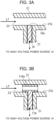
- FIGS. 2A and 2B are cross-sectional views of a nozzle of a sprayer, in which FIG. 2A is an enlarged cross-sectional view of the nozzle of FIG. 1 , and FIG. 2B is a view along arrows Y-Y in FIG. 2A .
- FIGS. 3A and 3B are cross-sectional views schematically illustrating a configuration of an electrode.
- a spray ionization device 10 includes: a sprayer 11; a container 12 containing a sample liquid Lf to be supplied to the sprayer 11; a cylinder 13 for containing a spraying gas Gf to be supplied to the sprayer 11; and a high-voltage power source 14 for applying high voltage to the sample liquid Lf via an electrode 18.
- a nozzle 15 for ejecting electrically charged droplets is formed at one end (hereinafter also referred to as an ejection end) of the sprayer 11 of the spray ionization device 10.
- the sample liquid Lf and the spraying gas Gf are supplied from further toward the opposite end than the nozzle 15 (hereinafter also referred to as a supply end).
- the sample liquid Lf may be continuously or intermittently supplied from the container 12 by way of a pump 17 or the like.
- the sample liquid Lf may contain an analysis target in solvents, or may contain dissolved components, particulate matter, or the like, for example.
- the spraying gas Gf is supplied from the cylinder 13 through the valve 16 to the supply port 22s. Inert gas such as nitrogen gas or argon gas, or air can be used for the spraying gas Gf, for example.
- a heating unit 19 such as a heater or dryer for heating the spraying gas Gf may be provided between the cylinder 13 or the valve 16 and the supply port 22s. The spraying gas Gf is heated, whereby vaporization of solvents in the ejected sample liquid Lf can be promoted, and electrically charged droplets can be obtained more efficiently.
- the sprayer 11 includes a liquid supply tube 21 and a gas supply tube 22 that surrounds the liquid supply tube 21 with a gap.
- the liquid supply tube 21 and the gas supply tube 22 have a double tube structure, in which the tubes are preferably coaxial (central axis X-X) with one another.
- the liquid supply tube 21 extends from the supply end to the ejection end.
- the liquid supply tube 21 includes a first channel 23 being tubular and defined by an inner circumferential surface 21b of the liquid supply tube 21, and includes an outlet 21a of the nozzle 15 at the ejection end.
- a diameter (inner diameter) of the inner circumferential surface 21b of the liquid supply tube 21 is preferably 10 um to 250 um, and a diameter (outer diameter) of an outer circumferential surface 21c of the liquid supply tube 21 is preferably 100 um to 400 ⁇ m.
- an opening diameter of the outlet 21a is preferably 0.2 um to 150 ⁇ m.
- the liquid supply tube 21 may be made of a glass and plastic dielectric material.
- the electrode 18 is provided to the liquid supply tube 21 as described later.
- the gas supply tube 22 includes a second channel 24 defined by an inner circumferential surface 22b of the gas supply tube 22 and the outer circumferential surface 21c of the liquid supply tube 21, and includes an outlet 22a of the nozzle 15.
- a diameter (inner diameter) of the inner circumferential surface 22b of the gas supply tube 22 is not limited in particular, and is, for example, 4 mm, further toward the supply end than the nozzle 15.
- the gas supply tube 22 is made of a dielectric material such as glass or plastics, and is preferably made of silica glass, in particular, fused silica glass.
- the spraying gas Gf is pressurized and supplied from the supply port 22s of the gas supply tube 22, flows through the second channel 24, and is ejected from the outlet 22a.
- a flow rate of the spraying gas Gf is appropriately set in accordance with the flow rate of the sample liquid Lf, and is set to 0.5 L/min to 5.0 L/min, for example.
- the high-voltage power source 14 is a power source for generating high-voltage direct current voltage or high-frequency alternating-current voltage, and is connected to the electrode 18 arranged so as to be able to contact the sample liquid Lf flowing through the sprayer 11.
- the high-voltage power source 14 applies voltage of e.g., 4 kV to the electrode 18, and preferably applies voltage in a range of 0.5 kV to 10 kV in terms of ionization.
- the waveform is not limited in particular, and is a sine wave, a rectangular wave, or the like; and in the case of ionization utilizing a chemical reaction, the frequency is preferably 100 Hz to 1000 kHz.
- the electrode 18 is provided further toward the supply end than the outlet 21a of the liquid supply tube 21, for example, at the supply end of the liquid supply tube 21.
- the electrode 18 is formed so as to be able to contact the sample liquid Lf flowing through the first channel 23.
- the electrode 18 may be provided such that a distal end 18a of the electrode 18 forms a surface contiguous with the inner circumferential surface 21b of the liquid supply tube 21 or projects into the first channel 23.
- the distal end 18a may be provided so as to recede from the inner circumferential surface 21b of the liquid supply tube 21.
- the electrode 118 includes an annular member 118a in the first channel 23 such that the sample liquid Lf can flow through the inside of the annular member 118a.
- the electrode 18 or 118 is preferably made of a platinum-group element, gold, or alloy thereof, in terms of excellent corrosion resistance.
- the electrode 18 or 118 may be made of a metal material such as titanium or tungsten, which may be used for a common electrode.
- part or entirety of the liquid supply tube 21 may be made of an electrical conductor material to form the electrode 18.
- the outlet 21a of the liquid supply tube 21 may be made of an electrical conductor material to form the electrode 18.
- the outlet 22a of the gas supply tube 22 is arranged further toward the distal end than the outlet 21a of the liquid supply tube 21.
- the gas supply tube 22 is formed such that a portion 22b 1 of the inner circumferential surface of the gas supply tube 22 has a diameter that progressively decreases from upstream toward downstream.
- the channel area of the second channel 24 progressively decreases.
- the channel area refers to an area occupied by the second channel 24 on a plane perpendicular to the central axis X, in which the area is surrounded by the inner circumferential surface 22b of the gas supply tube 22 and the outer circumferential surface 21c of the liquid supply tube 21 as illustrated in FIG. 2B .
- the gas supply tube 22 is formed such that the diameter of the inner circumferential surface of the outlet 22a of the gas supply tube 22 is equal to or larger than the opening diameter of the outlet 21a of the surface liquid supply tube 21.
- the flow of the ejected sample liquid Lf focuses by the spraying gas Gf, whereby droplets are atomized. Since the electrode 18 applies high voltage supplied from the high-voltage power source 14 to the sample liquid Lf, the ejected and atomized droplets have been charged. In this manner, the spray ionization device 10 can eject atomized and electrically charged droplets.
- the nozzle 15 of the sprayer 11 preferably includes a constriction portion 26 in the second channel 24, in which the channel area of the second channel 24 is the smallest.
- the constriction portion 26 is provided to a portion 22d, in which the inner circumferential surface 22b of the gas supply tube 22 has a diameter that progressively decreases from upstream toward downstream, and the distance between the inner circumferential surface 22b and the outer circumferential surface 21c of the liquid supply tube 21 is the smallest.
- the outer circumferential surface 21c of the liquid supply tube 21 has a diameter that progressively decreases from upstream toward the outlet 21a at a first rate per length in the X-axis direction;
- the inner circumferential surface 22b of the gas supply tube 22 has a diameter that progressively decreases at a second rate per length in the X-axis direction; and the second rate is set greater than the first rate, whereby the constriction portion 26 is formed at the portion 22d.
- a distance between the portion 22d of the inner circumferential surface of the gas supply tube 22 and the outer circumferential surface 21c of the liquid supply tube 21 is preferably set to 5 um to 20 ⁇ m.
- the constriction portion 26 is arranged upstream of the outlet 21a of the liquid supply tube 21
- This arrangement increases the pressure of the spraying gas Gf flowing through the second channel 24 at the constriction portion 26, increases the flow rate (linear velocity) of the spraying gas Gf having passed through the constriction portion 26, and promoting the atomization of the sample liquid Lf ejected from the outlet 21a of the liquid supply tube 21.
- Droplets ejected from the outlet 21a of the liquid supply tube 21 can be further suppressed from flowing backward through the second channel 24 and entering the constriction portion 26.
- clogging of the constriction portion 26 due to precipitation of components such as salts contained in droplets can be suppressed, whereby stable ejection can be achieved.
- This arrangement achieves a flow-focusing effect, in which droplets ejected from the outlet 21a can be ejected at a narrower angle (i.e., in a smaller lateral spreading range with respect to the ejection direction) than the case without the constriction portion 26.
- the constriction portion 26 is preferably provided 50 um to 2000 um upstream from the outlet 21a.
- the diameter of the inner circumferential surface 22b 2 of the gas supply tube 22 in the vicinity of the outlet 22a may progressively increase from the portion 22d of the constriction portion 26 toward the outlet 22a.
- the channel area of the second channel 24 is progressively widened toward the outlet 22a.
- the outer circumferential surface 21c of the liquid supply tube 21 may have a constant outer diameter toward the outlet 21a, or may have a diameter that progressively decreases as illustrated in FIG. 2A .
- a position 21e, at which the diameter of the outer circumferential surface 21c starts to decrease, is preferably formed upstream of the constriction portion 26.
- the outlet 21a of the liquid supply tube 21 preferably has an opening diameter smaller than the diameter of the inner circumferential surface 22b of the gas supply tube 22 at the constriction portion 26.
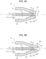
- FIGS. 4A and 4B are cross-sectional views illustrating alternative examples of the gas supply tube of the nozzle of the sprayer.
- the gas supply tube 22 is preferably formed in the nozzle 65 such that at least a portion 72b 2 of the inner circumferential surface of the gas supply tube 22 has a diameter that progressively decreases from the portion 22d of the constriction portion 26 toward the outlet 72a, and the opening diameter (D2) of the outlet 72a of the gas supply tube 22 is equal to or smaller than the diameter D1 (further toward the supply end than the portion 21e) of the outer circumferential surface 21c of the liquid supply tube, at the tip of the outlet 21a of the liquid supply tube 21.
- the formation satisfies a relationship of D1 ⁇ D2.
- the flow-focus effect is further enhanced, in which the ejected, atomized and electrically charged droplets can flow at a narrower angle than the case of the nozzle 15 illustrated in FIGS. 2A and 2B .
- the gas supply tube 22 is formed in the nozzle 75 such that: a portion 72b 2 of the inner circumferential surface of the gas supply tube 22 has a diameter that progressively decreases downstream from the portion 22d of the constriction portion 26; the diameter of the inner circumferential surface of the gas supply tube 22 is the smallest at a portion 82e, further toward the tip than the outlet 21a of the liquid supply tube; and the inner circumferential surface 82b 3 has a diameter that progressively increases toward the outlet 82a, further toward the tip than the outlet 21a of the liquid supply tube.
- An opening diameter D3 of a portion 82e, at which the diameter of the inner circumferential surface of the gas supply tube 22 is the smallest, is formed to be equal to or smaller than the diameter D1 (further toward the supply end than the portion 21e) of the outer circumferential surface 21c of the liquid supply tube.
- the formation satisfies a relationship of D1 ⁇ D3.
- FIG. 5A and FIG. 5B are cross-sectional views of the nozzle of the first variation of the sprayer according to the first embodiment of the present invention, in which FIG. 5A is an enlarged cross-sectional view, and FIG. 5B is a view along arrows Y-Y in FIG. 5A .
- the sprayer of the first variation of the first embodiment includes: the liquid supply tube 21; a gas supply tube 122; a protective tube 127 surrounding the liquid supply tube 21 and provided between the liquid supply tube 21 and the gas supply tube 122; and an electrode 18 for applying high voltage to the sample liquid Lf flowing through the liquid supply tube 21.
- the electrode 18 has the same configuration as illustrated in FIGS. 1 , 3A and 3B .
- the sprayer has a triple tube structure, in which the tubes are preferably coaxial (central axis X-X) with one another.
- the liquid supply tube 21 has the same configuration as the liquid supply tube 21 illustrated in FIGS. 1 , 2A and 2B .
- a second channel 124 of the gas supply tube 122 is a space defined by the outer circumferential surface 127c of the protective tube 127 and the inner circumferential surface 122b of the gas supply tube 122, in which the spraying gas Gf flows through the second channel 124. Note that the spraying gas Gf is not supplied to a space defined by the outer circumferential surface 21c of the liquid supply tube 21 and the inner circumferential surface of the protective tube 127.
- the inner circumferential surface 122b of the gas supply tube 122 has the same shape as the inner circumferential surface 22b of the gas supply tube 22 illustrated in FIGS. 2A and 2B .
- the spray ionization device including the sprayer of the first variation can eject the atomized and electrically charged droplets.
- a constriction portion 126 of the second channel 124 is preferably formed by the outer circumferential surface 127c of the tip 127a of the protective tube 127 and the portion 122b 1 of the inner circumferential surface of the gas supply tube 122.
- the second channel 124 is formed such that the channel area of the second channel 124 progressively decreases from the supply end to the constriction portion 126.
- the spraying gas Gf passes through the constriction portion 126 to gain the flow velocity, and the flow of electrically charged droplets of the sample liquid Lf ejected from the outlet 21a of the liquid supply tube 21 further focuses, promoting atomization of droplets.
- the gas supply tube 122 is formed such that the inner circumferential surface 122b 2 has a constant diameter (inner diameter) from the constriction portion 126 toward the outlet 122a. As a result, the flow of the spraying gas Gf ejected from the constriction portion 126 is not blocked by any members, whereby turbulence can be suppressed from being generated.
- the gas supply tube 122 may be formed such that the inner circumferential surface 122b 2 of the gas supply tube 122 has a diameter that progressively increases from the constriction portion 126 toward the outlet 122a. As a result, the same effects as in the case of the constant diameter can be achieved.
- the gas supply tube 122 may be configured as illustrated in FIGS. 4A and 4B .
- FIGS. 6A and 6B are cross-sectional views of an alternative example of the gas supply tube of the nozzle of the first variation.
- the gas supply tube 122 is formed in the nozzle 165 such that: at least a portion 172b 2 of the inner circumferential surface of the gas supply tube 122 has a diameter that progressively decreases from the portion 122d of the constriction portion 126 toward an outlet 172a; and an opening diameter (D5) of the outlet of the gas supply tube is formed to be equal to or smaller than the diameter D4 of the outer circumferential surface 127c of the protective tube 127, further toward the tip than the outlet 21a of the liquid supply tube 21.
- the formation satisfies a relationship of D4 ⁇ D5.
- the flow-focus effect can be further enhanced, and the ejected, atomized and electrically charged droplets can form a flow at a narrower angle
- the gas supply tube 122 is formed in the nozzle 175 such that: the portion 172b 2 of the inner circumferential surface of the gas supply tube 122 has a diameter that progressively decreases downward from the portion 122d of the constriction portion 126; the diameter of the inner circumferential surface of the gas supply tube 122 is the smallest at a portion 182e, further toward the tip than the outlet 21a of the liquid supply tube; and the inner circumferential surface 182b 3 has a diameter that progressively increases toward the outlet 182a.
- the opening diameter D6 of the portion 182e, at which the diameter of the inner circumferential surface of the gas supply tube 122 is the smallest, is formed to be equal to or smaller than the diameter D4 of the outer circumferential surface 127c of the protective tube 127. Specifically, the formation satisfies a relationship D4 ⁇ D6. As a result, the same flow-focus effect as that of the nozzle 165 of FIG. 6A can be achieved, and the content of the sample liquid Lf becomes more unlikely to adhere to the inner circumferential surface 182b 3 , and clogging becomes more unlikely to occur even if an operation is continued for a long time.
- the opening diameter (diameter) of the outlet 21a of the liquid supply tube 21 is preferably smaller than the diameter of the outer circumferential surface 127c of the tip 127a of the protective tube 127 in the constriction portion 126.
- the nozzle 115 may include, instead of the constriction portion 126, a constriction portion similar to the constriction portion 26 formed by the outer circumferential surface 21c of the liquid supply tube 21 and the portion 22d of the inner circumferential surface of the gas supply tube 22, which is illustrated in FIGS. 2A and 2B .
- the constriction portion may be formed by the outer circumferential surface 21c of the liquid supply tube 21 and any one of the portion 122b 1 in which the inner circumferential surface 122b of the gas supply tube 122 has a diameter that progressively decreases toward the outlet 122a, the portion 122d having the smallest inner diameter, or the portion 122b 2 having the constant inner diameter.
- FIG. 7 is an enlarged cross-sectional view of the nozzle of a second variation of the sprayer of the first embodiment of the present invention.
- the nozzle 215 of the second variation includes a blocking member 228 in a gap between the outer circumferential surface 21c of the liquid supply tube 21 and the inner circumferential surface 127b of the protective tube 127, at the tip 127a toward the ejection end of the protective tube 127, in which the gap is blocked by the blocking member 228.
- the nozzle 215 has the same configuration as the nozzle 215 of the sprayer of the first variation illustrated in FIGS. 5A and 5B .
- the blocking member 228 prevents the spraying gas Gf having passed through the constriction portion 126 from entering the gap between the outer circumferential surface 21c of the liquid supply tube 21 and the inner circumferential surface 127b of the protective tube 127.
- the blocking member 228 may be provided entirely along the axial direction of the gap between the outer circumferential surface 21c of the liquid supply tube 21 and the inner circumferential surface 127b of the protective tube 127.
- a spray ionization device has substantially the same configuration as the spray ionization device according to the first embodiment illustrated in FIG. 1 , and description of the same elements are omitted.
- FIGS. 8A and 8B are cross-sectional views of a nozzle of the spray ionization device according to the second embodiment of the present invention, in which FIG. 8A is an enlarged cross-sectional view of the nozzle, and FIG. 8B is a view along arrows Y-Y in FIG. 8A illustrating the nozzle.
- the sprayer of the spray ionization device includes: a liquid supply tube 21; a gas supply tube 322; and an electrode 18 for applying high voltage to a sample liquid Lf flowing through the liquid supply tube 21.
- the electrode 18 has the same configuration as illustrated in FIGS. and 3B.
- the sprayer has a double tube structure, in which the tubes are preferably coaxial (central axis X-X) with one another.
- the liquid supply tube 21 has substantially the same configuration as the liquid supply tube 21 of the first embodiment illustrated in FIGS. 1 , 2A and 2B .
- the liquid supply tube 21 includes a first channel 23 defined by the inner circumferential surface of the liquid supply tube 21 and extending in the axial direction.
- the sample liquid Lf flows through the liquid supply tube 21 and is ejected from an outlet 21a.
- the gas supply tube 322 has substantially the same configuration as the gas supply tube 22 illustrated in FIGS. 1 , 2A and 2B .
- the gas supply tube 322 includes a second channel 324 defined by the inner circumferential surface 322b of the gas supply tube 322 and the outer circumferential surface 21c of the liquid supply tube 21 and extending in the axial direction.
- the spraying gas Gfs flows through the second channel 324.
- the outlet 21a of the liquid supply tube 21 is located further toward the supply end than the outlet 322a of the gas supply tube 322.
- the gas supply tube 322 includes an ejection port 322d between the outlet 322a of the gas supply tube 322 and the outlet 21a of the liquid supply tube 21.
- the ejection port 322d is a portion in which the diameter of the inner circumferential surface of the gas supply tube 322 is the smallest, and the ejection port 322d is formed narrower than the opening of the outlet 21a of the liquid supply tube 21.
- the opening diameter of the ejection port 322d is smaller than the opening diameter of the outlet 21a of the liquid supply tube 21.
- the sample liquid Lf ejected from the outlet 21a of the liquid supply tube 21 collides with the spraying gas Gf having flowed through the second channel 324, at high speed in the region between the outlet 21a and the ejection port 322d, whereby the electrically charged droplets of the sample liquid Lf are atomized and ejected from the outlet 322a through the ejection port 322d.
- the second channel 324 preferably includes a constriction portion 326 in which the channel area of the second channel 324 is the smallest.
- the constriction portion 326 is formed by a gap between a portion 322b 1 , in which the inner circumferential surface 322b of the gas supply tube 322 has a diameter that progressively decreases from upstream to downstream, and the outer circumferential surface 21c of the outlet 21a of the liquid supply tube 21.
- the spraying gas Gf gains linear velocity in the constriction portion 326 and collides with the sample liquid Lf at high speed in the region between the outlet 21a of the liquid supply tube 21 and the ejection port 322d, whereby atomization of electrically charged droplets of the sample liquid Lf is promoted.
- the spraying gas Gf is ejected from the constriction portion 326 at high speed; therefore, the content of the sample liquid Lf is unlikely to adhere to the vicinity of the ejection port 322d, and clogging is unlikely to occur.
- the liquid supply tube 21 is supported in a cantilever manner at the supply end, whereby when the spraying gas Gf is ejected from the constriction portion 326 at high speed, the outlet 21a of the liquid supply tube 21 easily vibrates in a direction perpendicular to the ejection direction. Then, the gap at the constriction portion 326 temporally changes, so that the flow rate of the spraying gas Gf having passed through the constriction portion 326 changes, and the spraying gas flows locally at higher speed. As a result, the content of the sample liquid Lf is further unlikely to adhere to the vicinity of the ejection port 322d, and clogging is further unlikely to occur.
- FIGS. 9A and 9B are views illustrating a nozzle of a first variation of the sprayer according to the second embodiment of the present invention, in which FIG. 9A is an enlarged cross-sectional view, and FIG. 9B is a view of the nozzle from the ejection end.
- the sprayer of the first variation of the second embodiment includes a liquid supply tube 21, a gas supply tube 422, and an electrode 18 for applying high voltage to the sample liquid Lf flowing through the liquid supply tube 21.
- the electrode 18 has the same configuration as illustrated in FIGS. 1 and 3B .
- the sprayer has a double tube structure, in which the tubes are preferably coaxial (central axis X-X) with one another.
- the liquid supply tube 21 has the same configuration as the liquid supply tube 21 of the second embodiment illustrated in FIGS. 8A and 8B , and the sample liquid Lf is ejected from the outlet 21a.
- the gas supply tube 422 includes a second channel 424 defined by the inner circumferential surface 422b of the gas supply tube 422 and the outer circumferential surface 21c of the liquid supply tube 21 and extending in the axial direction.
- the spraying gas Gf flows through the second channel 424 and is ejected from the outlet 422a.
- a reticulated member 430 is provided to the outlet 422a of the gas supply tube 422.
- the reticulated member 430 is retained by a retaining member 422h and arranged so as to cover the opening of the outlet 422a of the gas supply tube 422.
- a sheet-like mesh sheet can be used for the reticulated member 430.
- a dielectric material can be used for the mesh sheet, and for example, nylon fiber can be used.
- the reticulated member 430 has horizontal lines 430x and vertical lines 430y with an interval of 70 ⁇ m, for example, in which a vertical and horizontal size of each aperture is 35 ⁇ m, for example.
- the distance between the outlet 21a of the liquid supply tube 21 and the reticulated member 430 is set to 100 ⁇ m, for example, and is preferably set to 5 um to 300 ⁇ m.
- FIG. 10 is an enlarged cross-sectional view of a nozzle of a second variation of the sprayer of the second embodiment of the present invention.
- the second variation of the sprayer of the second embodiment includes a liquid supply tube 21, a gas supply tube 522, and an electrode 18 for applying high voltage to the sample liquid Lf flowing through the liquid supply tube 21.
- the electrode 18 has the same configuration as illustrated in FIGS. 1 and 3B .
- the sprayer has a double tube structure, in which the tubes are preferably coaxial (central axis X-X) with one another.
- the liquid supply tube 21 has the same configuration as the liquid supply tube 21 of the second embodiment illustrated in FIGS. 8A and 8B , and the sample liquid Lf is ejected from the outlet 21a.
- the gas supply tube 522 includes a second channel 524 defined by the inner circumferential surface 522b of the gas supply tube 522 and the outer circumferential surface 21c of the liquid supply tube 21 and extending in the axial direction.
- the spraying gas Gf flows through the second channel 524 and is ejected from the outlet 522a.
- the inner circumferential surface 522b of the gas supply tube 522 has a diameter that decreases at a portion 522k further toward the tip than the outlet 21a of the liquid supply tube 21, and the inner circumferential surface 522b 1 is bent perpendicularly to the X-axis direction.
- a bent portion 524k bent toward the outlet 21a of the liquid supply tube 21 is formed in the second channel 524.
- the inner circumferential surface 522b 1 of the gas supply tube 522 is bent perpendicularly to the X-axis direction, or may be bent at an angle that is larger or smaller than the vertical angle, depending on the flow velocity or the like of the spraying gas Gf.
- the spraying gas Gf enters the inside of the liquid supply tube 21 from the outlet 21a and collides with the electrically charged droplets of the sample liquid Lf, whereby atomization of the electrically charged droplets of the sample liquid Lf is promoted.
- the ejection port 522d may be provided with the reticulated member 430 of the sprayer of the first variation illustrated in FIGS. 9A and 9B . As a result, atomization of electrically charged droplets of the sample liquid Lf is further promoted.
- a second gas supply tube may be provided so as to surround the gas supply tube with a gap.
- FIG. 11 is a diagram schematically illustrating a configuration of another variation of the spray ionization device according to the second embodiment of the present invention.
- a spray ionization device 610 includes a second gas supply tube 628 in which a sprayer 611 surrounds a gas supply tube 322, and the nozzle 315 is the nozzle 315 illustrated in FIGS. 8A and 8B .
- a cylinder 613 supplies sheath gas Gf 2 via a valve 616 to a supply port 628s of the second gas supply tube 628.
- the second gas supply tube 628 includes a third channel 629 defined by an outer circumferential surface 322c of the gas supply tube 322 and an inner circumferential surface 628b of the second gas supply tube 628 and extending in the axial direction.
- the inner circumferential surface 628b of the second gas supply tube 628 is formed so as to have a constant diameter toward an outlet 628a.
- the flow of sheath gas Gf 2 flowing through the third channel 629 is restricted from spreading by the inner circumferential surface 628b of the second gas supply tube 628 toward the outlet 628a, and the atomized and electrically charged droplets ejected from the nozzle 315 are enveloped in the sheath gas Gf 2 .
- the outlet 628a of the second gas supply tube 628 ejects the focused, atomized and electrically charged droplets along the axis in the ejection direction.
- a heating unit 619 may be provided downstream of the valve 616 so as to supply the sheath gas Gf 2 as heated gas; or a heating unit such as a ring heater (not illustrated) may be provided downstream of the outlet 322a of the gas supply tube 322 so as to surround a second gas supply tube 622. As a result, desolvation of droplets can be supported.
- the sprayer 611 can employ the nozzle 415 illustrated in FIGS. 9A and 9B or the nozzle 515 illustrated in FIG. 10 , which achieve the same effects as the nozzle 315.
- the sprayer 611 may employ the nozzle 15 illustrated in FIGS. 2A and 2B , the nozzle 65 or 75 illustrated in FIGS. 4A and 4B , the nozzle 115 illustrated in FIGS. 5A and 5B , the nozzle 165 or 175 illustrated in FIGS. 6A and 6B , or the nozzle 215 illustrated FIG. 7 of the first embodiment.
- FIG. 12 is a diagram schematically illustrating a configuration of the alternative example of the second gas supply tube of another variation of the spray ionization device.
- a second gas supply tube 728 of a sprayer 711 of a spray ionization device 710 has the same configuration as the second gas supply tube 628, except that the tip shape of the second gas supply tube 728 differs from the tip shape of the second gas supply tube 628 illustrated in FIG. 11 .
- An inner circumferential surface 728b of the second gas supply tube 728 is formed to have a diameter that progressively decreases toward an outlet 728a, and the channel area of a third channel 729 progressively decreases accordingly.
- the sheath gas Gf 2 flowing through the third channel 729 flows toward the outlet 728a such that the flow focuses while being restricted by the inner circumferential surface 728b of the second gas supply tube 728.
- the atomized and electrically charged droplets ejected from the nozzle 315 are enveloped in the sheath gas Gf 2 and focus onto the axial center along the ejection direction, and the focused, atomized and electrically charged droplets are ejected from the outlet 728a of the second gas supply tube 728.
- FIG. 13 is a diagram schematically illustrating a configuration of an analysis device according to an embodiment of the present invention.
- an analysis device 700 includes a spray ionization device 10 and an analysis unit 701 for introducing atomized and electrically charged droplets from the spray ionization device 10 and performing mass spectrometry or the like.
- the spray ionization device 10 is selected from the spray ionization devices of the first and second embodiments described above.
- the spray ionization device 10 sends the ejected, atomized and electrically charged droplets of the sample liquid Lf to the analysis unit 701.
- the atomized and electrically charged droplets are introduced into the analysis unit 701 in a state in which the molecules, clusters, and the like of components contained in the sample liquid are electrically charged by evaporation of solvents.
- the analysis unit 701 includes, for example, an ion lens, a quadrupole mass filter, and a detection unit (all not illustrated).
- the ion lens focuses ions of the components of the sample liquid Lf generated by the spray ionization device 10, the quadrupole mass filter separates out specific ions based on a mass-to-charge ratio, the detection unit detects the specific ions for each mass number, and outputs corresponding signals.
- the spray ionization device 10 efficiently generates ions of components of the sample liquid and can therefore be used as an ion source of trace components.
- the analysis device 700 is a liquid chromatography-mass spectrometry (LC/MS) device including the spray ionization device 10 as an ion source.
- LC/MS liquid chromatography-mass spectrometry
- Example 1 is the spray ionization device of the first variation of the first embodiment, in which the sprayer including the nozzle 115 illustrated in FIGS. 5A and 5B was used.
- Example 2 is the spray ionization device of the first variation of the second embodiment, in which the sprayer including the nozzle 415 illustrated in FIGS. 9A and 9B was used.
- the inner diameter of the liquid supply tube 21 is 110 ⁇ m
- the inner diameter of the gas supply tube is 170 um
- the vertical and horizontal size of each aperture of the reticulated member is 35 um.
- a sprayer (ESI-probe (ion source)) attached to model API2000, a mass spectrometer manufactured by AB SCIEX, U.S.A. was used in the Comparative Example.
- dAMP Deoxyadenosine monophosphate
- a dAMP solution having 50 ppm concentration was prepared as a sample solution.
- This sample solution was supplied into the sprayer of Examples 1 and 2 and the Comparative Example at a flow rate of 3 ⁇ L/min by a syringe pump.
- a high-voltage power source manufactured by AB SCIEX, Model API2000 equipment was connected to the electrode, and DC voltage of 4.5 kV was applied to the sample solution.
- Nitrogen gas was used as the spraying gas, nitrogen gas was supplied at 1 L/min in Examples 1 and 2, and nitrogen gas was supplied at a set value of 18 as a recommended value of the manufacturer of the mass spectrometer in the Comparative Example.
- FIG. 14 is a diagram illustrating a Measurement Example of signal intensity of Examples 1 and 2 and the Comparative Example.
- FIG. 14 illustrates average values and RSD of the signal intensity.
- the average values of the signal intensity of Examples 1 and 2 were 5.45 ⁇ 10 8 counts and 1.06 ⁇ 10 8 counts, respectively, which were 20 times and 3.8 times the intensity of the Comparative Example which was 2.76 ⁇ 10 7 count, respectively.
- RSDs of the signal intensity of Examples 1 and 2 were 1.3% and 7.1%, respectively, and extremely smaller than RSD of the Comparative Example, which was 43.2%. This fact shows that the sprayers of Examples 1 and 2 were able to ionize dAMP extremely more stably than the sprayer of the Comparative Example.
- Example 1 10% acetonitrile aqueous solution as a sample solution was supplied into the sprayers of Example 1 and the Comparative Example at a flow rate of 100 ⁇ L/min, signal intensity was counted for one second per measurement by the same mass spectrometer as in Measurement Example 1, measurement was performed six times, and an average value was calculated.
- Nitrogen gas was used as spraying gas, the flow rate was set to 1 L/min and 2 L/min, and the temperature was set to 25°C and 100°C, in Example 1.
- a dryer was used for heating the spraying gas.
- nitrogen gas of 100°C and 300°C was ejected from a heating gas nozzle attached to the mass spectrometer at a set value 30 as recommended by the manufacturer of the mass spectrometer.
- a high-voltage power source manufactured by AB SCIEX, Model API2000 equipment
- DC voltage of 4.5 kV was applied to the sample solution.
- FIGS. 15A and 15B are diagrams illustrating another Measurement Example of signal intensity of Example 1 and the Comparative Example, in which FIG. 15A illustrates a case in which the spraying gas was at 25°C and FIG. 15B illustrates a case in which the spraying gas was heated.
- an average of the signal intensity of Example 1 was 3.56 ⁇ 10 6 counts and 7.60 ⁇ 10 6 counts at the flow rates of 1 L/min and 2 L/min, respectively, which were 5 times and 10 times the strength of the Comparative Example, which was 7.26 ⁇ 10 5 counts, respectively. This fact shows that the sprayer of Example 1 was able to perform ionization extremely more efficiently than the sprayer of the Comparative Example and provide higher signal values.
- an average of the signal intensity was 5.54 ⁇ 10 7 counts for the spraying gas at 100°C and the flow rate of 2 L/min of Example 1, which was 6 times and 1.4 times the intensity of the Comparative Example, which was 8.79 ⁇ 10 6 counts and 3.97 ⁇ 10 7 counts for the heated gas at 100°C and 300°C, respectively.
- This fact shows that, even in the case in which the ejection gas was heated, the sprayer of Example 1 was able to perform ionization extremely more efficiently than the sprayer of the Comparative Example and provide higher signal values.
- a high-voltage power source manufactured by AB SCIEX, Model API2000 equipment
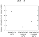
- FIG. 16 is a diagram illustrating a Measurement Example of signal intensity of dAMP of Example 1 and the Comparative Example.
- the signal intensity of Example 1 was 3.9 ⁇ 10 6 counts, which was six times the intensity of the Comparative Example which was 6.5 ⁇ 10 5 counts for the gas heated to 100°C, and twice the intensity of the Comparative Example which was 1.8 ⁇ 10 6 counts for the gas heated to 300°C. This fact shows that the sprayer of Example 1 was able to perform ionization extremely more efficiently than the sprayer of the Comparative Example and provide higher signal values.
- the shape of the cross-section and the channel of the liquid supply tube has been described as circular, but may be triangular, square, pentagonal, hexagonal or other polygonal shapes, or other shapes such as an elliptical shape.
- the shape of the outer circumferential surface and the inner circumferential surface of the gas supply tube and the second gas supply tube can be selected from these shapes, depending on the shape of the liquid supply tube.
- the spray ionization device of the present invention can be used as an ion source of various devices; for example, in the field of trace sample analysis, the spray ionization device can be used for mass spectrometry such as mass spectrometry of molecules in a biological sample, elemental analysis, chemical morphology analysis, and charged particle analysis.
- the spray ionization device of the present invention can be used for surface coating devices utilizing surface coating techniques of spraying electrically charged droplets, and particle forming devices utilizing particle forming techniques by spraying electrically charged droplets of suspension.
- the spray ionization device of the present invention can be used for space processing devices utilizing sterilization, deodorization, dust collection, and chemical reactions, utilizing gas-phase or spatial chemical reactions by spraying electrically charged droplets.
Claims (19)
- Sprühionisationsvorrichtung (10, 610, 710), umfassend:ein erstes Rohr (21) mit einem ersten Kanal (23), durch welchen eine Flüssigkeit strömen kann, wobei das erste Rohr (21) einen ersten Auslass für den Ausstoß der Flüssigkeit an einem Ende und ein gegenüberliegendes Zuführende aufweist;ein das erste Rohr (21) mit einem Spalt umschließendes zweites Rohr (22, 122) und enthaltend einen zweiten Kanal (24, 124), durch welchen ein Gas strömen kann, wobei das zweite Rohr (22, 122) einen zweiten Auslass an dem einen Ende aufweist, der zweite Kanal (24, 124) durch eine äußere Umfangsfläche des ersten Rohres (21) und eine innere Umfangsfläche des zweiten Rohres (22, 122) definiert wird; undeine Elektrode (118), die die durch den ersten Kanal (23) strömende Flüssigkeit kontaktieren kann, wobei die Elektrode (118) weiter in Richtung auf das Zuführende vorgesehen ist als der erste Auslass (21a) des ersten Rohres (21) und geeignet ist, mittels einer Stromquelle (14), die an die Elektrode (118) angeschlossen ist, eine Spannung an die Flüssigkeit anzulegen,wobei die Elektrode ein ringförmiges Element (118a) umfasst, das in dem ersten Kanal (23) angeordnet ist und derart konfiguriert ist, dass die Flüssigkeit durch eine Innenseite des ringförmigen Elements (118A) strömen kann, wobei an dem einen Ende der zweite Auslass weiter in Richtung auf eine Spitze angeordnet ist als der erste Auslass, zumindest ein Abschnitt der inneren Umfangsfläche des zweiten Rohres (22, 122) einen in Richtung auf den zweiten Auslass progressiv abnehmenden Durchmesser aufweist und ein Durchmesser der inneren Umfangsfläche des zweiten Auslasses gleich einem oder größer als ein Öffnungsdurchmesser des ersten Auslasses ist undwobei elektrisch geladene Tröpfchen der Flüssigkeit aus dem zweiten Auslass ausgestoßen werden können.
- Sprühionisationsvorrichtung (10, 610, 710) nach Anspruch 1, wobei der zweite Kanal (24) einen Verengungsbereich (26) aufweist, der weiter in Richtung auf das gegenüberliegende Ende angeordnet ist als der erste Auslass, und wobei eine Kanalfläche des zweiten Kanals (24) von dem gegenüberliegenden Ende zu dem Verengungsbereich (26) progressiv abnimmt.
- Sprühionisationsvorrichtung (10, 610, 710) nach Anspruch 2, wobei der erste Auslass des ersten Rohres (21) einen Öffnungsdurchmesser aufweist, der kleiner ist als der Durchmesser der inneren Umfangsfläche des zweiten Rohres (22) in dem Verengungsbereich (26).
- Sprühionisationsvorrichtung (10, 610, 710) nach Anspruch 1, ferner umfassend:ein drittes Rohr (127) zwischen dem ersten Rohr (21) und dem zweiten Rohr (122), wobei das dritte Rohr (127) das erste Rohr (21) umschließt und dem einen Ende einen dritten Auslass an aufweist,wobei der zweite Kanal (124), durch welche das Gas hindurchströmen kann, durch eine äußere Umfangsfläche des dritten Rohres (127) und die innere Umfangsfläche des zweiten Rohres (122) definiert wird undwobei an dem einen Ende eine Spitze des dritten Rohres (127) weiter in Richtung auf das gegenüberliegende Ende angeordnet ist als der erste Auslass.
- Sprühionisationsvorrichtung (10, 610, 710) nach Anspruch 4, wobei das dritte Rohr (127) einen Verengungsbereich (126) aufweist, der durch eine Spitze der äußeren Umfangsfläche an dem einen Ende des dritten Rohres (127) und die innere Umfangsfläche des zweiten Rohres (122) definiert wird.
- Sprühionisationsvorrichtung (10, 610, 710) nach Anspruch 5, wobei das zweite Rohr (122) derart ausgebildet ist, dass zumindest ein Abschnitt der inneren Umfangsfläche des zweiten Rohres (122) einen Durchmesser aufweist, der von einem Abschnitt des Verengungsbereichs (126) in Richtung auf den zweiten Auslass progressiv abnimmt.
- Sprühionisationsvorrichtung (10, 610, 710) nach Anspruch 4 oder 5, wobei an einer Spitze an dem einen Ende des dritten Rohres (127) ein dielektrisches Material den Spalt zwischen einer inneren Umfangsfläche des dritten Rohres (127) und der äußeren Umfangsfläche des ersten Rohres (21) füllt.
- Sprühionisationsvorrichtung (10, 610, 710), umfassend:ein erstes Rohr (21) mit einem ersten Kanal (23), durch welchen eine Flüssigkeit strömen kann, wobei das erste Rohr (21) einen ersten Auslass für den Ausstoß der Flüssigkeit an einem Ende und ein gegenüberliegendes Zuführende aufweist;ein das erste Rohr (21) mit einem Spalt umschließendes zweites Rohr (322, 422, 522) und enthaltend einen zweiten Kanal (324, 424, 522), durch welchen ein Gas strömen kann, wobei das zweite Rohr (322, 424, 524) einen zweiten Auslass aufweist, der weiter in Richtung auf die Spitze angeordnet ist als der erste Auslass an dem einen Ende, wobei der zweite Kanal (324, 424, 524) durch eine äußere Umfangsfläche des ersten Rohres (21) und eine innere Umfangsfläche des zweiten Rohres (22, 122) definiert wird;eine Elektrode (118), die die durch den ersten Kanal (23) strömende Flüssigkeit kontaktieren kann, wobei die Elektrode (118) weiter in Richtung auf das Zuführende vorgesehen ist als der erste Auslass (21a) des ersten Rohres (21) und geeignet ist, mittels einer Stromquelle (14), die an die Elektrode (118) angeschlossen ist, eine Spannung an die Flüssigkeit anzulegen und wobei die Elektrode ein ringförmiges Element (118a) umfasst, das in dem ersten Kanal (23) angeordnet ist und derart konfiguriert ist, dass die Flüssigkeit durch eine Innenseite des ringförmigen Elements (118a) strömen kann; und ein netzartiges Element (430), das den zweiten Auslass abdeckt, oder eine Öffnung im zweiten Rohr (322, 522) zwischen dem ersten Auslass und dem zweiten Auslass, wobei die Öffnung schmaler ist als eine Öffnung des ersten Auslasses,wobei elektrisch geladene Tröpfchen der Flüssigkeit aus dem zweiten Auslass ausgestoßen werden können.
- Sprühionisationsvorrichtung (10, 610, 710) nach Anspruch 8, wobei an dem einen Ende der zweite Kanal (542) einen gebogenen Abschnitt aufweist, der in Richtung auf den ersten Auslass gebogen ist.
- Sprühionisationsvorrichtung (10, 610, 710) nach Anspruch 8, wobei der zweite Kanal (324) einen Verengungsbereich (326) aufweist, der derart gebildet ist, dass zumindest ein Abschnitt des zweiten Kanals (324) in Richtung auf den zweiten Auslass verengt ist.
- Sprühionisationsvorrichtung (10, 610, 710) nach Anspruch 8, wobei, wenn das netzartige Element (430) vorgesehen ist, der zweite Auslass eine Öffnung aufweist, die breiter ist als die Öffnung des ersten Auslasses.
- Sprühionisationsvorrichtung (10, 610, 710) nach einem der Ansprüche 1 bis 11, ferner umfassend:eine Quelle für das Gas; undeine Heizeinheit (19) zum Erwärmen des Gases zwischen der Quelle und einer Zuführöffnung, die an dem gegenüberliegenden Ende des ersten Rohres (21) vorgesehen ist.
- Sprühionisationsvorrichtung (10, 610, 710) nach einem der Ansprüche 1 bis 12, wobei die Elektrode (118) ein elektrisches Leitermaterial ist, das derart vorgesehen ist, dass es in dem ersten Kanal (23) exponiert ist, oder ein elektrisches Leitermaterial, das zumindest einen Abschnitt des ersten Rohres (21) bildet.
- Sprühionisationsvorrichtung (10, 610, 710) nach einem der Ansprüche 1 bis 13, ferner umfassend:
eine Hochspannungsquelle (14), die an die Elektrode (118) angeschlossen ist, wobei die Hochspannungsquelle (14) an die Elektrode (118) eine Spannung in einem Bereich von 0,5 kV bis 10 kV anlegt. - Sprühionisationsvorrichtung (610, 710) nach einem der Ansprüche 1 bis 14, ferner umfassend:
ein viertes Rohr (628, 728), welches das zweite Rohr (22, 122, 322, 422, 522) mit einem Spalt umschließt und einen dritten Kanal (629, 729) enthält, durch welchen ein Gas strömen kann, wobei das vierte Rohr (628, 728) einen dritten Auslass an einem Ende aufweist, wobei der dritte Kanal (629, 729) durch die äußere Umfangsfläche des zweiten Rohres (22, 122, 322, 422, 522) und eine innere Umfangsfläche des dritten Rohres (127) definiert wird. - Sprühionisationsvorrichtung (710) nach Anspruch 15, wobei an dem einen Ende der dritte Auslass weiter in Richtung auf die Spitze angeordnet ist als der zweite Auslass und wobei eine innere Umfangsfläche des vierten Rohres (728) einen Durchmesser aufweist, der zumindest in Richtung auf den dritten Auslass progressiv abnimmt.
- Sprühionisationsvorrichtung (610, 710) nach Anspruch 15 oder 16, ferner umfassend:
eine zweite Heizeinheit (619) zum Erwärmen des zweiten Gases oder elektrisch geladener Tröpfchen der Flüssigkeit, die zusammen mit dem die elektrisch geladenen Tröpfchen der Flüssigkeit umhüllenden Gas aus dem Auslass ausgestoßen wird. - Analysevorrichtung (700), umfassend:die Sprühionisationsvorrichtung (10, 610, 710) nach einem der Ansprüche 1 bis 17; undeine Analyseeinheit (701), die die von der Sprühionisationsvorrichtung (10, 610, 710) versprühten elektrisch geladenen Tröpfchen einführt und analysiert.
- Oberflächenbeschichtungsvorrichtung, umfassend die Sprühionisationsvorrichtung (10, 610, 710) gemäß einem der Ansprüche 1 bis 17.
Applications Claiming Priority (2)
| Application Number | Priority Date | Filing Date | Title |
|---|---|---|---|
| JP2019097836 | 2019-05-24 | ||
| PCT/JP2020/016540 WO2020241098A1 (ja) | 2019-05-24 | 2020-04-15 | スプレーイオン化装置、分析装置および表面塗布装置 |
Publications (3)
| Publication Number | Publication Date |
|---|---|
| EP3951379A1 EP3951379A1 (de) | 2022-02-09 |
| EP3951379A4 EP3951379A4 (de) | 2022-06-01 |
| EP3951379B1 true EP3951379B1 (de) | 2023-11-22 |
Family
ID=73552862
Family Applications (1)
| Application Number | Title | Priority Date | Filing Date |
|---|---|---|---|
| EP20813374.4A Active EP3951379B1 (de) | 2019-05-24 | 2020-04-15 | Sprüh-ionisationsvorrichtung, analysevorrichtung und oberflächenbeschichtungsvorrichtung |
Country Status (4)
| Country | Link |
|---|---|
| US (1) | US20220305505A1 (de) |
| EP (1) | EP3951379B1 (de) |
| JP (1) | JP7198528B2 (de) |
| WO (1) | WO2020241098A1 (de) |
Families Citing this family (2)
| Publication number | Priority date | Publication date | Assignee | Title |
|---|---|---|---|---|
| JP7186471B2 (ja) * | 2019-07-31 | 2022-12-09 | 国立研究開発法人産業技術総合研究所 | スプレーイオン化装置、分析装置および表面塗布装置 |
| CN218944144U (zh) * | 2022-10-25 | 2023-05-02 | 广州国家实验室 | 一种喷雾喷头及喷雾装置 |
Citations (3)
| Publication number | Priority date | Publication date | Assignee | Title |
|---|---|---|---|---|
| US6140640A (en) * | 1999-02-25 | 2000-10-31 | Water Investments Limited | Electrospray device |
| US20100072394A1 (en) * | 2008-09-25 | 2010-03-25 | Vilmos Kertesz | Pulsed voltage electrospray ion source and method for preventing analyte electrolysis |
| US20170025262A1 (en) * | 2015-07-23 | 2017-01-26 | Beijing Institute Of Technology | Electrospray Ionization Source and LC-MS Interface |
Family Cites Families (10)
| Publication number | Priority date | Publication date | Assignee | Title |
|---|---|---|---|---|
| JPH06310088A (ja) * | 1993-04-23 | 1994-11-04 | Hitachi Ltd | 質量分析装置イオン源 |
| JP4370510B2 (ja) * | 2003-12-25 | 2009-11-25 | 努 升島 | 質量分析用エレクトロスプレーイオン化ノズル |
| JP4254546B2 (ja) * | 2004-01-09 | 2009-04-15 | 株式会社島津製作所 | 質量分析装置 |
| GB2456131B (en) * | 2007-12-27 | 2010-04-28 | Thermo Fisher Scient | Sample excitation apparatus and method for spectroscopic analysis |
| US8039795B2 (en) * | 2008-04-04 | 2011-10-18 | Agilent Technologies, Inc. | Ion sources for improved ionization |
| CA2833675C (en) | 2011-04-20 | 2019-01-15 | Micromass Uk Limited | Atmospheric pressure ion source by interacting high velocity spray with a target |
| JP5240806B2 (ja) * | 2011-12-22 | 2013-07-17 | 独立行政法人産業技術総合研究所 | プラズマを用いて試料をイオン化もしくは原子化して分析を行う分析装置用の噴霧器および分析装置 |
| US8772709B2 (en) * | 2012-07-16 | 2014-07-08 | Bruker Daltonics, Inc. | Assembly for an electrospray ion source |
| US10978287B2 (en) * | 2017-09-14 | 2021-04-13 | Shimadzu Corporation | ESI sprayer and ionizer |
| WO2019065405A1 (ja) * | 2017-09-26 | 2019-04-04 | 国立研究開発法人産業技術総合研究所 | ノズルおよびスプレー |
-
2020
- 2020-04-15 WO PCT/JP2020/016540 patent/WO2020241098A1/ja unknown
- 2020-04-15 JP JP2021522691A patent/JP7198528B2/ja active Active
- 2020-04-15 EP EP20813374.4A patent/EP3951379B1/de active Active
- 2020-04-15 US US17/608,811 patent/US20220305505A1/en active Pending
Patent Citations (3)
| Publication number | Priority date | Publication date | Assignee | Title |
|---|---|---|---|---|
| US6140640A (en) * | 1999-02-25 | 2000-10-31 | Water Investments Limited | Electrospray device |
| US20100072394A1 (en) * | 2008-09-25 | 2010-03-25 | Vilmos Kertesz | Pulsed voltage electrospray ion source and method for preventing analyte electrolysis |
| US20170025262A1 (en) * | 2015-07-23 | 2017-01-26 | Beijing Institute Of Technology | Electrospray Ionization Source and LC-MS Interface |
Non-Patent Citations (2)
| Title |
|---|
| FANG PAN ET AL: "A robust and extendable sheath flow interface with minimal dead volume for coupling CE with ESI-MS", TALANTA, vol. 180, 1 April 2018 (2018-04-01), NL, pages 376 - 382, XP093048188, ISSN: 0039-9140, DOI: 10.1016/j.talanta.2017.12.046 * |
| MAXWELL E J ET AL: "Twenty years of interface development for capillary electrophoresis-electrospray ionization-mass spectrometry", ANALYTICA CHIMICA ACTA, ELSEVIER, AMSTERDAM, NL, vol. 627, no. 1, 3 October 2008 (2008-10-03), pages 25 - 33, XP025408737, ISSN: 0003-2670, [retrieved on 20080627], DOI: 10.1016/J.ACA.2008.06.034 * |
Also Published As
| Publication number | Publication date |
|---|---|
| EP3951379A4 (de) | 2022-06-01 |
| WO2020241098A1 (ja) | 2020-12-03 |
| US20220305505A1 (en) | 2022-09-29 |
| JP7198528B2 (ja) | 2023-01-04 |
| EP3951379A1 (de) | 2022-02-09 |
| JPWO2020241098A1 (de) | 2020-12-03 |
Similar Documents
| Publication | Publication Date | Title |
|---|---|---|
| EP3951379B1 (de) | Sprüh-ionisationsvorrichtung, analysevorrichtung und oberflächenbeschichtungsvorrichtung | |
| US5873523A (en) | Electrospray employing corona-assisted cone-jet mode | |
| JP2019505953A (ja) | Esi動作中の放電を最小化するためのシステム | |
| US7960711B1 (en) | Field-free electrospray nebulizer | |
| EP3971564B1 (de) | Sprüh-ionisationsvorrichtung, analysevorrichtung und oberflächenbeschichtungsvorrichtung | |
| JP5589750B2 (ja) | 質量分析装置用イオン化装置及び該イオン化装置を備える質量分析装置 | |
| JP4556645B2 (ja) | 液体クロマトグラフ質量分析装置 | |
| JP2598566B2 (ja) | 質量分析計 | |
| JPH07288099A (ja) | 電気噴霧形成のための絶縁された針装置 | |
| US8716675B2 (en) | Methods and apparatus for mass spectrometry utilizing an AC electrospray device | |
| JP2004139962A (ja) | エレクトロスプレー質量分析装置 | |
| EP4082669A1 (de) | Sprüh-ionisationsvorrichtung | |
| CN112106170A (zh) | 撞击电离喷雾离子源或电喷雾电离离子源 | |
| JP6945894B2 (ja) | 噴霧器、試料導入ユニットおよび分析装置 | |
| EP4086935A1 (de) | Sprüh-ionisationsvorrichtung, analysevorrichtung und oberflächenbeschichtungsvorrichtung | |
| CN111052302A (zh) | 具有不对称喷雾的apci离子源 | |
| JP4254546B2 (ja) | 質量分析装置 | |
| US20220328300A1 (en) | Method and device for improved performance with micro-electrospray ionization | |
| JP4389515B2 (ja) | 質量分析装置 | |
| US20220001405A1 (en) | Plasma torch, plasma generator, and analysis device | |
| US20240027409A1 (en) | Gas flow nebulizer | |
| JP2012058122A (ja) | 液体クロマトグラフ質量分析装置 |
Legal Events
| Date | Code | Title | Description |
|---|---|---|---|
| STAA | Information on the status of an ep patent application or granted ep patent |
Free format text: STATUS: THE INTERNATIONAL PUBLICATION HAS BEEN MADE |
|
| PUAI | Public reference made under article 153(3) epc to a published international application that has entered the european phase |
Free format text: ORIGINAL CODE: 0009012 |
|
| STAA | Information on the status of an ep patent application or granted ep patent |
Free format text: STATUS: REQUEST FOR EXAMINATION WAS MADE |
|
| 17P | Request for examination filed |
Effective date: 20211104 |
|
| AK | Designated contracting states |
Kind code of ref document: A1 Designated state(s): AL AT BE BG CH CY CZ DE DK EE ES FI FR GB GR HR HU IE IS IT LI LT LU LV MC MK MT NL NO PL PT RO RS SE SI SK SM TR |
|
| A4 | Supplementary search report drawn up and despatched |
Effective date: 20220503 |
|
| RIC1 | Information provided on ipc code assigned before grant |
Ipc: H01J 49/16 20060101ALI20220426BHEP Ipc: B05B 7/06 20060101ALI20220426BHEP Ipc: B05B 5/025 20060101ALI20220426BHEP Ipc: G01N 27/62 20210101AFI20220426BHEP |
|
| DAV | Request for validation of the european patent (deleted) | ||
| DAX | Request for extension of the european patent (deleted) | ||
| STAA | Information on the status of an ep patent application or granted ep patent |
Free format text: STATUS: EXAMINATION IS IN PROGRESS |
|
| 17Q | First examination report despatched |
Effective date: 20221122 |
|
| REG | Reference to a national code |
Ref country code: DE Ref legal event code: R079 Ref document number: 602020021617 Country of ref document: DE Free format text: PREVIOUS MAIN CLASS: G01N0027620000 Ipc: B05B0005000000 Ref country code: DE Ref legal event code: R079 Free format text: PREVIOUS MAIN CLASS: G01N0027620000 Ipc: B05B0005000000 |
|
| RIC1 | Information provided on ipc code assigned before grant |
Ipc: B05B 5/03 20060101ALI20230523BHEP Ipc: B05B 5/053 20060101ALI20230523BHEP Ipc: B05B 5/04 20060101ALI20230523BHEP Ipc: H01J 49/16 20060101ALI20230523BHEP Ipc: B05B 7/06 20060101ALI20230523BHEP Ipc: B05B 5/16 20060101ALI20230523BHEP Ipc: B05B 5/00 20060101AFI20230523BHEP |
|
| GRAP | Despatch of communication of intention to grant a patent |
Free format text: ORIGINAL CODE: EPIDOSNIGR1 |
|
| STAA | Information on the status of an ep patent application or granted ep patent |
Free format text: STATUS: GRANT OF PATENT IS INTENDED |
|
| INTG | Intention to grant announced |
Effective date: 20230727 |
|
| GRAS | Grant fee paid |
Free format text: ORIGINAL CODE: EPIDOSNIGR3 |
|
| GRAA | (expected) grant |
Free format text: ORIGINAL CODE: 0009210 |
|
| STAA | Information on the status of an ep patent application or granted ep patent |
Free format text: STATUS: THE PATENT HAS BEEN GRANTED |
|
| AK | Designated contracting states |
Kind code of ref document: B1 Designated state(s): AL AT BE BG CH CY CZ DE DK EE ES FI FR GB GR HR HU IE IS IT LI LT LU LV MC MK MT NL NO PL PT RO RS SE SI SK SM TR |
|
| REG | Reference to a national code |
Ref country code: GB Ref legal event code: FG4D |
|
| REG | Reference to a national code |
Ref country code: CH Ref legal event code: EP |
|
| REG | Reference to a national code |
Ref country code: DE Ref legal event code: R096 Ref document number: 602020021617 Country of ref document: DE |
|
| REG | Reference to a national code |
Ref country code: IE Ref legal event code: FG4D |
|
| REG | Reference to a national code |
Ref country code: LT Ref legal event code: MG9D |
|
| REG | Reference to a national code |
Ref country code: NL Ref legal event code: MP Effective date: 20231122 |
|
| PG25 | Lapsed in a contracting state [announced via postgrant information from national office to epo] |
Ref country code: GR Free format text: LAPSE BECAUSE OF FAILURE TO SUBMIT A TRANSLATION OF THE DESCRIPTION OR TO PAY THE FEE WITHIN THE PRESCRIBED TIME-LIMIT Effective date: 20240223 |
|
| PG25 | Lapsed in a contracting state [announced via postgrant information from national office to epo] |
Ref country code: IS Free format text: LAPSE BECAUSE OF FAILURE TO SUBMIT A TRANSLATION OF THE DESCRIPTION OR TO PAY THE FEE WITHIN THE PRESCRIBED TIME-LIMIT Effective date: 20240322 |
|
| PG25 | Lapsed in a contracting state [announced via postgrant information from national office to epo] |
Ref country code: LT Free format text: LAPSE BECAUSE OF FAILURE TO SUBMIT A TRANSLATION OF THE DESCRIPTION OR TO PAY THE FEE WITHIN THE PRESCRIBED TIME-LIMIT Effective date: 20231122 |
|
| REG | Reference to a national code |
Ref country code: AT Ref legal event code: MK05 Ref document number: 1633362 Country of ref document: AT Kind code of ref document: T Effective date: 20231122 |
|
| PG25 | Lapsed in a contracting state [announced via postgrant information from national office to epo] |
Ref country code: NL Free format text: LAPSE BECAUSE OF FAILURE TO SUBMIT A TRANSLATION OF THE DESCRIPTION OR TO PAY THE FEE WITHIN THE PRESCRIBED TIME-LIMIT Effective date: 20231122 |
|
| PG25 | Lapsed in a contracting state [announced via postgrant information from national office to epo] |
Ref country code: AT Free format text: LAPSE BECAUSE OF FAILURE TO SUBMIT A TRANSLATION OF THE DESCRIPTION OR TO PAY THE FEE WITHIN THE PRESCRIBED TIME-LIMIT Effective date: 20231122 |
|
| PG25 | Lapsed in a contracting state [announced via postgrant information from national office to epo] |
Ref country code: ES Free format text: LAPSE BECAUSE OF FAILURE TO SUBMIT A TRANSLATION OF THE DESCRIPTION OR TO PAY THE FEE WITHIN THE PRESCRIBED TIME-LIMIT Effective date: 20231122 |
|
| PG25 | Lapsed in a contracting state [announced via postgrant information from national office to epo] |
Ref country code: NL Free format text: LAPSE BECAUSE OF FAILURE TO SUBMIT A TRANSLATION OF THE DESCRIPTION OR TO PAY THE FEE WITHIN THE PRESCRIBED TIME-LIMIT Effective date: 20231122 Ref country code: LT Free format text: LAPSE BECAUSE OF FAILURE TO SUBMIT A TRANSLATION OF THE DESCRIPTION OR TO PAY THE FEE WITHIN THE PRESCRIBED TIME-LIMIT Effective date: 20231122 Ref country code: IS Free format text: LAPSE BECAUSE OF FAILURE TO SUBMIT A TRANSLATION OF THE DESCRIPTION OR TO PAY THE FEE WITHIN THE PRESCRIBED TIME-LIMIT Effective date: 20240322 Ref country code: GR Free format text: LAPSE BECAUSE OF FAILURE TO SUBMIT A TRANSLATION OF THE DESCRIPTION OR TO PAY THE FEE WITHIN THE PRESCRIBED TIME-LIMIT Effective date: 20240223 Ref country code: ES Free format text: LAPSE BECAUSE OF FAILURE TO SUBMIT A TRANSLATION OF THE DESCRIPTION OR TO PAY THE FEE WITHIN THE PRESCRIBED TIME-LIMIT Effective date: 20231122 Ref country code: BG Free format text: LAPSE BECAUSE OF FAILURE TO SUBMIT A TRANSLATION OF THE DESCRIPTION OR TO PAY THE FEE WITHIN THE PRESCRIBED TIME-LIMIT Effective date: 20240222 Ref country code: AT Free format text: LAPSE BECAUSE OF FAILURE TO SUBMIT A TRANSLATION OF THE DESCRIPTION OR TO PAY THE FEE WITHIN THE PRESCRIBED TIME-LIMIT Effective date: 20231122 Ref country code: PT Free format text: LAPSE BECAUSE OF FAILURE TO SUBMIT A TRANSLATION OF THE DESCRIPTION OR TO PAY THE FEE WITHIN THE PRESCRIBED TIME-LIMIT Effective date: 20240322 |