EP3950488A1 - Schwimmende aquatische stützvorrichtung - Google Patents
Schwimmende aquatische stützvorrichtung Download PDFInfo
- Publication number
- EP3950488A1 EP3950488A1 EP20786731.8A EP20786731A EP3950488A1 EP 3950488 A1 EP3950488 A1 EP 3950488A1 EP 20786731 A EP20786731 A EP 20786731A EP 3950488 A1 EP3950488 A1 EP 3950488A1
- Authority
- EP
- European Patent Office
- Prior art keywords
- floating
- support rod
- ball
- water
- type
- Prior art date
- Legal status (The legal status is an assumption and is not a legal conclusion. Google has not performed a legal analysis and makes no representation as to the accuracy of the status listed.)
- Withdrawn
Links
Images


Classifications
-
- B—PERFORMING OPERATIONS; TRANSPORTING
- B63—SHIPS OR OTHER WATERBORNE VESSELS; RELATED EQUIPMENT
- B63B—SHIPS OR OTHER WATERBORNE VESSELS; EQUIPMENT FOR SHIPPING
- B63B39/00—Equipment to decrease pitch, roll, or like unwanted vessel movements; Apparatus for indicating vessel attitude
- B63B39/02—Equipment to decrease pitch, roll, or like unwanted vessel movements; Apparatus for indicating vessel attitude to decrease vessel movements by displacement of masses
-
- B—PERFORMING OPERATIONS; TRANSPORTING
- B63—SHIPS OR OTHER WATERBORNE VESSELS; RELATED EQUIPMENT
- B63B—SHIPS OR OTHER WATERBORNE VESSELS; EQUIPMENT FOR SHIPPING
- B63B35/00—Vessels or similar floating structures specially adapted for specific purposes and not otherwise provided for
- B63B35/44—Floating buildings, stores, drilling platforms, or workshops, e.g. carrying water-oil separating devices
-
- F—MECHANICAL ENGINEERING; LIGHTING; HEATING; WEAPONS; BLASTING
- F03—MACHINES OR ENGINES FOR LIQUIDS; WIND, SPRING, OR WEIGHT MOTORS; PRODUCING MECHANICAL POWER OR A REACTIVE PROPULSIVE THRUST, NOT OTHERWISE PROVIDED FOR
- F03D—WIND MOTORS
- F03D13/00—Assembly, mounting or commissioning of wind motors; Arrangements specially adapted for transporting wind motor components
- F03D13/20—Arrangements for mounting or supporting wind motors; Masts or towers for wind motors
- F03D13/25—Arrangements for mounting or supporting wind motors; Masts or towers for wind motors specially adapted for offshore installation
- F03D13/256—Arrangements for mounting or supporting wind motors; Masts or towers for wind motors specially adapted for offshore installation on a floating support, i.e. floating wind motors
-
- B—PERFORMING OPERATIONS; TRANSPORTING
- B63—SHIPS OR OTHER WATERBORNE VESSELS; RELATED EQUIPMENT
- B63B—SHIPS OR OTHER WATERBORNE VESSELS; EQUIPMENT FOR SHIPPING
- B63B1/00—Hydrodynamic or hydrostatic features of hulls or of hydrofoils
- B63B1/02—Hydrodynamic or hydrostatic features of hulls or of hydrofoils deriving lift mainly from water displacement
- B63B1/10—Hydrodynamic or hydrostatic features of hulls or of hydrofoils deriving lift mainly from water displacement with multiple hulls
- B63B1/14—Hydrodynamic or hydrostatic features of hulls or of hydrofoils deriving lift mainly from water displacement with multiple hulls the hulls being interconnected resiliently or having means for actively varying hull shape or configuration
-
- B—PERFORMING OPERATIONS; TRANSPORTING
- B63—SHIPS OR OTHER WATERBORNE VESSELS; RELATED EQUIPMENT
- B63B—SHIPS OR OTHER WATERBORNE VESSELS; EQUIPMENT FOR SHIPPING
- B63B15/00—Superstructures, deckhouses, wheelhouses or the like; Arrangements or adaptations of masts or spars, e.g. bowsprits
- B63B2015/0016—Masts characterized by mast configuration or construction
- B63B2015/005—Masts characterized by mast configuration or construction with means for varying mast position or orientation with respect to the hull
- B63B2015/0066—Inclinable masts with passive righting means, e.g. counterbalancing means
-
- B—PERFORMING OPERATIONS; TRANSPORTING
- B63—SHIPS OR OTHER WATERBORNE VESSELS; RELATED EQUIPMENT
- B63B—SHIPS OR OTHER WATERBORNE VESSELS; EQUIPMENT FOR SHIPPING
- B63B17/00—Vessels parts, details, or accessories, not otherwise provided for
- B63B2017/0072—Seaway compensators
-
- B—PERFORMING OPERATIONS; TRANSPORTING
- B63—SHIPS OR OTHER WATERBORNE VESSELS; RELATED EQUIPMENT
- B63B—SHIPS OR OTHER WATERBORNE VESSELS; EQUIPMENT FOR SHIPPING
- B63B35/00—Vessels or similar floating structures specially adapted for specific purposes and not otherwise provided for
- B63B35/44—Floating buildings, stores, drilling platforms, or workshops, e.g. carrying water-oil separating devices
- B63B2035/4433—Floating structures carrying electric power plants
- B63B2035/4453—Floating structures carrying electric power plants for converting solar energy into electric energy
-
- B—PERFORMING OPERATIONS; TRANSPORTING
- B63—SHIPS OR OTHER WATERBORNE VESSELS; RELATED EQUIPMENT
- B63B—SHIPS OR OTHER WATERBORNE VESSELS; EQUIPMENT FOR SHIPPING
- B63B35/00—Vessels or similar floating structures specially adapted for specific purposes and not otherwise provided for
- B63B35/44—Floating buildings, stores, drilling platforms, or workshops, e.g. carrying water-oil separating devices
- B63B2035/4433—Floating structures carrying electric power plants
- B63B2035/446—Floating structures carrying electric power plants for converting wind energy into electric energy
-
- B—PERFORMING OPERATIONS; TRANSPORTING
- B63—SHIPS OR OTHER WATERBORNE VESSELS; RELATED EQUIPMENT
- B63B—SHIPS OR OTHER WATERBORNE VESSELS; EQUIPMENT FOR SHIPPING
- B63B2209/00—Energy supply or activating means
- B63B2209/18—Energy supply or activating means solar energy
-
- B—PERFORMING OPERATIONS; TRANSPORTING
- B63—SHIPS OR OTHER WATERBORNE VESSELS; RELATED EQUIPMENT
- B63B—SHIPS OR OTHER WATERBORNE VESSELS; EQUIPMENT FOR SHIPPING
- B63B2209/00—Energy supply or activating means
- B63B2209/20—Energy supply or activating means wind energy
-
- B—PERFORMING OPERATIONS; TRANSPORTING
- B63—SHIPS OR OTHER WATERBORNE VESSELS; RELATED EQUIPMENT
- B63B—SHIPS OR OTHER WATERBORNE VESSELS; EQUIPMENT FOR SHIPPING
- B63B2221/00—Methods and means for joining members or elements
- B63B2221/20—Joining substantially rigid elements together by means that allow one or more degrees of freedom, e.g. hinges, articulations, pivots, universal joints, telescoping joints, elastic expansion joints, not otherwise provided for in this class
- B63B2221/22—Joining substantially rigid elements together by means that allow one or more degrees of freedom, e.g. hinges, articulations, pivots, universal joints, telescoping joints, elastic expansion joints, not otherwise provided for in this class by means that allow one or more degrees of angular freedom, e.g. hinges, articulations, pivots, universal joints, not otherwise provided for in this class
-
- F—MECHANICAL ENGINEERING; LIGHTING; HEATING; WEAPONS; BLASTING
- F03—MACHINES OR ENGINES FOR LIQUIDS; WIND, SPRING, OR WEIGHT MOTORS; PRODUCING MECHANICAL POWER OR A REACTIVE PROPULSIVE THRUST, NOT OTHERWISE PROVIDED FOR
- F03D—WIND MOTORS
- F03D13/00—Assembly, mounting or commissioning of wind motors; Arrangements specially adapted for transporting wind motor components
- F03D13/20—Arrangements for mounting or supporting wind motors; Masts or towers for wind motors
- F03D13/25—Arrangements for mounting or supporting wind motors; Masts or towers for wind motors specially adapted for offshore installation
-
- F—MECHANICAL ENGINEERING; LIGHTING; HEATING; WEAPONS; BLASTING
- F05—INDEXING SCHEMES RELATING TO ENGINES OR PUMPS IN VARIOUS SUBCLASSES OF CLASSES F01-F04
- F05B—INDEXING SCHEME RELATING TO WIND, SPRING, WEIGHT, INERTIA OR LIKE MOTORS, TO MACHINES OR ENGINES FOR LIQUIDS COVERED BY SUBCLASSES F03B, F03D AND F03G
- F05B2240/00—Components
- F05B2240/90—Mounting on supporting structures or systems
- F05B2240/93—Mounting on supporting structures or systems on a structure floating on a liquid surface
-
- F—MECHANICAL ENGINEERING; LIGHTING; HEATING; WEAPONS; BLASTING
- F05—INDEXING SCHEMES RELATING TO ENGINES OR PUMPS IN VARIOUS SUBCLASSES OF CLASSES F01-F04
- F05B—INDEXING SCHEME RELATING TO WIND, SPRING, WEIGHT, INERTIA OR LIKE MOTORS, TO MACHINES OR ENGINES FOR LIQUIDS COVERED BY SUBCLASSES F03B, F03D AND F03G
- F05B2240/00—Components
- F05B2240/90—Mounting on supporting structures or systems
- F05B2240/95—Mounting on supporting structures or systems offshore
-
- Y—GENERAL TAGGING OF NEW TECHNOLOGICAL DEVELOPMENTS; GENERAL TAGGING OF CROSS-SECTIONAL TECHNOLOGIES SPANNING OVER SEVERAL SECTIONS OF THE IPC; TECHNICAL SUBJECTS COVERED BY FORMER USPC CROSS-REFERENCE ART COLLECTIONS [XRACs] AND DIGESTS
- Y02—TECHNOLOGIES OR APPLICATIONS FOR MITIGATION OR ADAPTATION AGAINST CLIMATE CHANGE
- Y02E—REDUCTION OF GREENHOUSE GAS [GHG] EMISSIONS, RELATED TO ENERGY GENERATION, TRANSMISSION OR DISTRIBUTION
- Y02E10/00—Energy generation through renewable energy sources
- Y02E10/50—Photovoltaic [PV] energy
-
- Y—GENERAL TAGGING OF NEW TECHNOLOGICAL DEVELOPMENTS; GENERAL TAGGING OF CROSS-SECTIONAL TECHNOLOGIES SPANNING OVER SEVERAL SECTIONS OF THE IPC; TECHNICAL SUBJECTS COVERED BY FORMER USPC CROSS-REFERENCE ART COLLECTIONS [XRACs] AND DIGESTS
- Y02—TECHNOLOGIES OR APPLICATIONS FOR MITIGATION OR ADAPTATION AGAINST CLIMATE CHANGE
- Y02E—REDUCTION OF GREENHOUSE GAS [GHG] EMISSIONS, RELATED TO ENERGY GENERATION, TRANSMISSION OR DISTRIBUTION
- Y02E10/00—Energy generation through renewable energy sources
- Y02E10/70—Wind energy
- Y02E10/727—Offshore wind turbines
Definitions
- the present invention relates to a floating-type on-water support apparatus, and more specifically, to a floating-type on-water support apparatus configured to maintain horizontality of a heavy offshore structure and support the heavy offshore structure.
- a floating-type on-water support apparatus which is disclosed in Public Patent No. 10-2017-0108900 and Registered Patent No. 10-1857949 and on which a wind power generator or another structure can be installed, is developed in order to install the wind power generator on the sea because a magnitude of wind is not large due to friction with the ground of the land.
- the above-disclosed floating-type on-water support apparatus includes a ball, a floating part, and a support rod.
- the floating part floats on water and supports the ball.
- the support rod is coupled to the ball, and one end of the support rod is heavier than the other end thereof. Accordingly, the support rod stands vertically.
- a wind power generator or another structure may be installed on one end of the support rod.
- a load of a support rod is focused on a portion which supports a ball of a floating part. Accordingly, there is a problem in that the portion supporting the ball of the floating part may not withstand the load and may be damaged.
- the support rod is coupled to the ball.
- the ball since the ball is supported by the floating part, the ball may be rotated. Accordingly, the support rod may also be rotated about a central axis thereof.
- the wind power generator when a wind power generator is installed on the support rod, the wind power generator may be rotated about the central axis. Then, since blades of the wind power generator are not directed to face the wind, there is a problem in that a power generation quantity is reduced.
- the present invention is directed to providing a floating-type on-water support apparatus allowing a floating part which supports a ball to be prevented from being damaged.
- the present invention is also directed to providing a floating-type on-water support apparatus allowing a support rod, which is configured to support a structure, to be prevented from being rotated about an axis of the support rod even when the support rod may be rotated about a ball.
- a floating-type on-water support apparatus including a ball, a floating unit, a support rod, and a base unit.
- the floating unit includes a floating part, wherein the floating part has an upper plate supporting the ball so that the ball is rotatable, an interior formed to be hollow, and a lower plate provided with a spherical surface portion and floats on water.
- One end of the support rod is exposed above the water so that a structure is installable thereon and the other end thereof is heavier than the one end so as to stand vertically to be accommodated in the floating part, and the support rod is coupled to the ball.
- One end of the base unit is installed on a lower portion of the support rod to support the support rod and the other end thereof is in roll contact with the spherical surface portion.
- a floating-type on-water support apparatus including a ball, a floating unit, a support rod, and a center pendulum.
- the floating unit includes a floating part, wherein the floating part has an upper plate supporting the ball so that the ball is rotatable, an interior formed to be hollow, and a lower plate provided with a spherical surface portion and floats on water.
- One end of a support rod is exposed above the water so that a structure is installable thereon and the other end thereof is coupled to the ball to stand vertically and be accommodated in the floating part.
- the center pendulum is positioned to be rolled on the spherical surface portion to press a lower end of the support rod so as to allow the support rod to stand.
- the lower end of the support rod may surround an upper portion of the center pendulum so that the center pendulum is not separated from the support rod.
- the support rod may be supported by the center pendulum using a bearing.
- the support rod may be slidably coupled to pass through the ball.
- a guide groove may be formed in the ball along a circumferential surface passing through the support rod.
- the floating unit further may include a restriction protrusion fitted into the guide groove to restrict rotation of the ball about an axis of the support rod.
- the floating unit may further include a fixing member used to install the restriction protrusion on the floating part.
- the ball may further include a fixing groove formed in the guide groove at two sides of the ball to be perpendicular to a central axis of the support rod.
- the restriction protrusion may be coupled to the fixing member to be moved toward or away from the fixing member in a radius direction of the ball so as to be fitted into the fixing groove.
- the fixing member may include a moving plate and a fixing frame.
- the moving plate may be coupled to the restriction protrusion so that the restriction protrusion is moved forward or rearward when the restriction protrusion is rotated and may be bent in a circumferential direction of the ball.
- the fixing frame may be coupled to the floating part to restrict the moving plate to slide only within a predetermined distance in the circumferential direction of the ball.
- the fixing member may further include a clamp coupled to the fixing frame to press the moving plate so as to fix sliding of the moving plate.
- a floating-type on-water support apparatus including a floating unit, a support unit, a base unit, and an installation base.
- the floating unit includes a floating part of which an interior is formed to be hollow so that the floating part floats on water and in which a spherical surface portion is formed on a lower surface in the interior.
- the support unit includes an upper support rod coupled to an upper portion of the floating part and a lower support rod of which one end is coupled to the upper support rod using a universal joint and the other end is heavier than the one end to stand vertically and is accommodated in the floating part.
- One end of the base unit is installed on the other end of the lower support rod to support the lower support rod and the other end thereof is in roll contact with the spherical surface portion.
- the installation base is exposed above the floating unit so that a structure is installable on one end thereof and is coupled to the lower support rod.
- the floating-type on-water support apparatus may further include a blocking cover coupled to the floating part to prevent water, on which the floating unit floats, from being introduced into the ball.
- a floating-type on-water support apparatus including a floating unit, a support unit, a center pendulum, and an installation base.
- the floating unit includes a floating part of which an interior is formed to be hollow so that the floating part floats on water and in which a spherical surface portion is formed on a lower surface in the interior.
- the support unit includes an upper support rod coupled to an upper portion of the floating part and a lower support rod coupled to the upper support rod using a universal joint and is accommodated in the floating part.
- the center pendulum is positioned to be rolled on the spherical surface portion to press a lower end of the lower support rod so as to allow the lower support rod to stand.
- the installation base is exposed above the floating unit so that a structure is installed one end thereof, and coupled to the lower support rod.
- the lower support rod may surround an upper portion of the center pendulum so that the center pendulum is not separated from the lower support rod.
- the lower support rod may be supported by the center pendulum using a bearing.
- the upper support rod may be coupled to an upper portion of the floating part to be vertically slidable.
- the floating-type on-water support apparatus may further include a blocking cover coupled to the floating part to prevent water from being introduced into the universal joint.
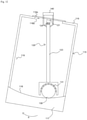
- FIGS. 1 to 5 One embodiment of a floating-type on-water support apparatus according to the present invention will be described with reference to FIGS. 1 to 5 .
- the floating-type on-water support apparatus includes a ball 10, a floating unit 15, a support rod 25, a base unit 30, and a solar panel 35.
- a guide groove 11 and fixing grooves 13 are formed in the ball 10.
- the guide groove 11 is formed along a circumferential surface of a virtual cross section passing through a center of the ball 10. That is, the guide groove 11 is formed along the circumferential surface in which a diameter of the ball 10 is defined.
- the fixing grooves 13 are formed in the guide groove 11 at two sides, which are opposite to each other, of the ball 10 in directions toward the center of the ball 10.
- the support rod 25 is coupled to the ball 10, and since the support rod 25 should stand vertically so that one end 25a of the support rod 25 is moved upward and the other end thereof is moved downward, the other end is formed to be heavier than the one end 25a.
- a structure such as a wind power generator may be installed on the one end 25a of the support rod 25.
- the support rod 25 is coupled to pass through the guide groove 11 and the center of the ball 10 to be perpendicular to the fixing grooves 13.
- a fluid may be injected into or is discharged from the support rod 25 as in the conventional invention.
- the floating unit 15 includes a floating part 16, restriction protrusions 17, and fixing members 20.
- the floating part 16 floats on water, and an interior of the floating part 16 is formed to be hollow to accommodate the other end of the support rod 25.
- An upper plate 16a of the floating part 16 supports the ball so that the ball 10 is rotatable.
- a ball accommodation part 16a_1 for accommodating and supporting the ball 10 is formed in the upper plate 16a. That is, the ball 10 may be seated and rotated in the ball accommodation part 16a_1.
- a spherical surface portion 16c is provided on a lower plate 16b.
- restriction protrusion 17 One end of the restriction protrusion 17 is fitted into the guide groove 11 so that the ball 10 is not rotated about an axis of the support rod 25.
- a screw is formed on the other end of the restriction protrusion 17 so that the restriction protrusion 17 is moved forward or rearward in the fixing member 20.
- the fixing members 20 serve to install the restriction protrusions 17 on the floating part 15.
- the fixing members 20 include moving plates 21, fixing frames 22, and clamps 23.
- the moving plate 21 is screw-coupled to the other end of the restriction protrusion 17 so that the restriction protrusion 17 is moved forward or rearward when the restriction protrusion 17 is rotated and is formed to be bent in a circumferential direction of the ball 10.
- the fixing frame 22 is coupled to the upper plate 16a of the floating part 16 so that the moving plate 21 is slidable within a predetermined distance in a curvature direction of the moving plate 21.
- the fixing frame 22 guides the moving plate 21 to slide, and in this case, collision bars 22a are formed to be spaced apart from each other by the distance so that the moving plate 21 collides with the restriction protrusion 17 after sliding the predetermined distance. That is, the restriction protrusion 17 may slide only between the collision bars 22a spaced apart from each other by the predetermined distance. Accordingly, the moving plate 21 is also slidable only within the predetermined distance like the collision bar 22a.
- the clamp 23 restricts sliding of the moving plate 21.
- the moving plate 21 should not slide and the moving plate 21 should be fixed to not slide.
- the sliding of the moving plate 21 may be restricted by the clamp 23.
- the clamp 23 is coupled to the fixing frame 22 to press the moving plate 21 when the clamp 23 is coupled to the fixing frame 22.
- the clamp 23 is screw-coupled to the fixing frame 22 to press the moving plate 21.
- One end 31 of the base unit 30 may be installed on a lower portion of the support rod 25 so that the lower plate 16b may support the support rod 25, and the other end 33 thereof is in contact with the spherical surface portion 16c.
- the other end 33 of the base unit 30 is in contact with the spherical surface portion 16c to be rollable thereon. Accordingly, the other end 33 may be implemented as a wheel, a ball, or the like.
- a structure may be installed on the one end 25a of the support rod 25. In this case, since a weight of the structure is large, an excessive weight may be applied to the upper plate 16a of the floating part 16. Accordingly, since the upper plate 16a may be damaged, the base unit 30 serves to disperse some of the weight applied to the support rod 25 to the lower plate 16b.
- the solar panel 35 is installed on the upper plate 16a of the floating part 16. Accordingly, the floating-type on-water support apparatus according to the present embodiment may be self-powered. In the case of the present embodiment, the solar panel 35 is installed on the upper plate of the floating part 16, but a vertical wind power generator may be installed instead of the solar panel 35, or both of the vertical wind power generator and the solar panel 35 may be installed thereon. The solar panel 35 and the vertical wind power generator may also be installed on any embodiment which will be described below.
- the support rod 25 stands vertically, and the one end 25a is moved upward from the sea and the other end is accommodated in the floating part 16.
- the wind power generator or the like is installed on the one end 25a of the support rod 25.
- the base unit 30 is in contact with the spherical surface portion 16c to be rollable on the spherical surface portion 16c. Accordingly, although the base unit 30 is in contact with the spherical surface portion 16c, as a frictional force is minimized, the floating part 16 may be shaken with respect to the support rod 25, and as illustrated in FIG. 5 , even when the floating part 16 or the support rod 25 are shaken, the base unit 30 is supported by the spherical surface portion 16c.
- the support rod 25 is not affected by a wave. That is, even when the wave hits the support rod 25, the floating part 16 is shaken but the support rod 25 is prevented from being shaken.
- the restriction protrusion 17 when the restriction protrusion 17 is rotated and fitted into the guide groove 11 of the ball 10, the ball 10 is prevented from being rotated about the axis of the support rod 25.
- the ball 10 is restricted from being rotated about the axis of the support rod 25 but may be rotated about an axis perpendicular to the axis of the support rod 25. Accordingly, even when a wave hits and shakes the floating part 16, the shaking of the floating part 16 is not transferred to the support rod 25.
- the moving plate 21, on which the restriction protrusion 17 is installed may slide the predetermined distance. Accordingly, the support rod 25 may be shaken about the axis of the support rod 25 within the predetermined distance.
- the moving plate 21 coupled to the restriction protrusion 17 may slide to reduce the impact.
- the moving plates 21 positioned at one side slides the moving plates 21 positioned at both sides of the ball 10 slide in the same direction.
- the moving plates 21 slide in the circumferential direction of the ball 10. Accordingly, even when the moving plates 21 slide, a predetermined distance between the restriction protrusions 17 positioned at both sides of the ball 10 is maintained. Accordingly, the restriction protrusions 17 are not separated from the guide groove 11 of the ball.
- the guide groove 11 is formed in the ball 10 and the restriction protrusion 17 is fitted into the guide groove 11, rotation about the axis of the support rod 25 may be restricted. Accordingly, in a case in which the wind power generator or the like is installed on the support rod 25, rotation of a shaft of the wind power generator due to wind may be prevented. However, in this case, the shaft of the wind power generator may be rotated within the predetermined distance within which the moving plate 21 is moved in the circumferential direction of the ball 10.
- the restriction protrusion 17 when the restriction protrusion 17 is rotated to be moved further forward, the restriction protrusion 17 is rotated and fitted into the fixing groove 13.
- the ball 10 may be restricted form being rotated in the other direction and may be rotated about an axis of the restriction protrusion 17.
- FIG. 6 is a view illustrating a floating-type on-water support apparatus according to another embodiment of the present invention.
- the embodiment of FIG. 6 further includes blocking covers 45 in addition to the embodiment of FIG. 1 .
- the blocking covers 45 are installed on a floating part 16 to prevent water from being introduced into a ball 10.
- the blocking covers 45 are formed of a flexible material to be deformed when the floating part 16 is shaken.
- FIG. 7 is a view illustrating a floating-type on-water support apparatus according to still another embodiment of the present invention.
- FIGS. 1 to 4 includes the restriction protrusion 17 and the fixing member 20 for restricting rotation of the ball 10.
- a restriction protrusion 18 is formed as a ball type to restrict rotation of a ball 10 and fitted into a guide groove 11.
- the ball 10 does not need a fixing groove 13, and a groove capable of accommodating the restriction protrusion 18 is formed in a floating part 16. Since the restriction protrusion 18 is accommodated in the floating part 16, a fixing member 20 is also not needed. Meanwhile, in order to reduce friction between the ball 10 and the floating part 16, a bearing 19 supporting the ball 10 may be installed in the floating part 16.
- FIG. 8 is a view illustrating a floating-type on-water support apparatus according to yet another embodiment of the present invention.
- the floating-type on-water support apparatus includes a ball 10, a floating unit, a support rod 26, and a center pendulum 40.
- the ball 10 and the floating unit are the same as those of the embodiment illustrated in FIGS. 1 to 5 .
- the floating unit includes a floating part 15, and the ball 10 may be restricted in the floating part 15 by a restriction protrusion 17 and a fixing member 20 as in FIG. 1 or by a restriction protrusion 18 as in FIG. 7 .
- the support rod 26 is coupled to the ball 10 so that one end thereof is exposed from the floating part 16 to the outside, and the other end thereof is accommodated in the floating part 16 like the embodiment illustrated in FIG. 1 .
- a structure such as a wind power generator or the like may be installed on one end of the support rod 26.
- a groove may be formed in the other end of the support rod 26 to surround an upper portion of the center pendulum 40 so that the center pendulum 40 is not separated from the support rod 26.
- the groove of the other end of the support rod 26 is formed to have a spherical surface to be supported by the center pendulum 40.
- the center pendulum 40 serves to stand the support rod 26 vertically. To this end, the center pendulum 40 is disposed on a spherical surface portion 16c of the floating part 16 to be rollable and positioned in the groove of the support rod 26 to support the support rod 26. In this case, since the center pendulum 40 supports the support rod 26 using bearings 19, friction between the center pendulum 40 and the support rod 26 may be minimized. Since the center pendulum 40 may roll on the spherical surface portion 16c, the center pendulum 40 always tries to be positioned at the lowest point of the spherical surface portion 16c. When the support rod 26 is inclined, since the center pendulum 40 is restricted by the support rod 26, the center pendulum 40 is moved upward.
- FIG. 9 is a view illustrating a floating-type on-water support apparatus according to yet another embodiment of the present invention.
- a support rod 26 passes through and is slidably installed in a ball 10 in addition to the embodiment of FIG. 8 .
- the center of the ball 10 matches with a center of the spherical surface portion 16c of the floating part 16, but in the embodiment of FIG. 9 , a center of the ball 10 does not need to match with a center of a spherical surface portion 16c.
- FIGS. 10 to 12 are views illustrating a floating-type on-water support apparatus according to another embodiment of the present invention.
- the floating-type on-water support apparatus according to another embodiment will be described with reference to FIGS. 10 to 12 .
- the floating-type on-water support apparatus includes a floating unit, a support unit 120, a center pendulum 130, and an installation base 140.
- the floating unit includes a floating part 115, and like the above-described embodiment, an accommodation part 119 is formed in the floating part 115, and a spherical surface portion 118 is formed on a lower surface 117. However, a through hole 116a is formed in an upper portion 116 so that an installation base 140 passes therethrough.
- the support unit 120 includes an upper support rod 121 and a lower support rod 123 and is installed in the accommodation part 119 of the floating part 115.
- the upper support rod 121 is coupled to the upper portion 116 of the floating part 115.
- an upper end of the upper support rod 121 is formed as a support plate 119a and is coupled to the upper portion 116 so that the support plate 119a is disposed across the through hole 116a.
- An upper end of the lower support rod 123 is coupled to a lower end of the upper support rod 121 using a universal joint 124. Accordingly, the upper support rod 121 may be rotated in front, rear, left, and right directions with respect to the lower support rod 123.
- a groove is formed in a lower portion of the lower support rod 123 to surround an upper portion of the center pendulum 130 so that the center pendulum 130 is not separated from the lower support rod 123.
- the lower portion of the lower support rod 123 is formed to have a spherical surface so as to be supported by the center pendulum 130.
- the center pendulum 130 serves to stand the lower support rod 123 up vertically. To this end, the center pendulum 130 is disposed on a spherical surface portion 118 of the floating part 115 to be rollable and positioned in the groove of the lower support rod 123 to support the lower support rod 123. In this case, since the center pendulum 130 supports the lower support rod 123 using bearings 131, friction between the center pendulum 130 and the lower support rod 123 may be minimized. Since the center pendulum 130 may be rollable on the spherical surface portion 118, the center pendulum 130 always tries to be positioned at the lowest point of the spherical surface portion 118.
- the installation base 140 is exposed above the floating unit so that a structure such as a wind power generator is installed thereon, passes through the through hole 116a of the floating part 115, and is coupled to the lower support rod 123. Accordingly, since the installation base 140 is integrally coupled to the lower support rod 123, an angle, which is the same as an angle of the lower support rod 123, of the installation base 140 is maintained. Accordingly, when the lower support rod 123 stands, the installation base 140 also stands. When the structure is installed on the installation base 140, some of a load applied to the installation base 140 is transferred to an upper portion 116 of the floating part 115, and the remaining load is supported by the center pendulum 130. Accordingly, even in the case of the present embodiment, the load of the structure is dispersed to the upper and lower portions of the floating part 115.
- the upper support rod 121 is coupled to the lower support rod 123 using the universal joint 124, the upper support rod 121 is rotatable in the front and rear or left and right directions with respect to the lower support rod 123. Accordingly, when a wave hits the floating part 115, as illustrated in FIG. 12 , the floating part 115 is shaken in the front and rear or left and right directions. Even when the floating part 115 is shaken in the front and rear or left and right directions, the center pendulum 130 is positioned at the lowest point of the spherical surface portion 118 due to the weight thereof.
- the lower support rod 123 Since the center pendulum 130 is restricted by the lower support rod 123, the lower support rod 123 is not shaken in the front and rear or left and right directions and stands vertically. Accordingly, even in the case of the present embodiment, since the installation base 140 stands vertically, when the wind power generator is installed on the installation base 140, the wind power generator may be maintained vertically regardless of a wave.
- FIG. 13 is a view illustrating a floating-type on-water support apparatus according to yet another embodiment of the present invention.
- the floating-type on-water support apparatus illustrated in FIG. 13 incudes a floating unit, a support unit 120, a base unit 30, and an installation base 140.
- the floating unit is the same as that of the embodiment illustrated in FIG. 10 and includes a floating part 115.
- the support unit 120 includes an upper support rod 121 and a lower support rod 124.
- a lower end of the lower support rod 124 is formed to be lighter than an upper end thereof like the support rod 25 of the embodiment illustrated in FIG. 1 .
- the lower support rod 124 stands vertically due to a weight thereof.
- the base unit 30 is in roll contact with a spherical surface portion of the floating part 115 to support the lower support rod 124 like the embodiment illustrated in FIG. 1 .
- the installation base 140 is the same as that of the embodiment illustrated in FIG. 10 .
- the lower support rod 124 may stand vertically due to a weight thereof, and a load applied to the installation base 140 may be dispersed to upper and lower portions of the floating part 115.
- FIG. 14 is a view illustrating a floating-type on-water support apparatus according to yet another embodiment of the present invention.
- a support unit 120 may vertically slide on an upper portion 116 of a floating part 115 in addition to the embodiment illustrated in FIG. 10 .
- the floating part 115 includes a guide 114 disposed on the upper portion 116, and an upper support rod 121 is installed to be vertically slidable along the guide 114. That is, in the embodiment illustrated in FIG. 10 , the upper support rod 121 is fixedly coupled to the upper portion 116 of the floating part 115, but in the case of the present embodiment, the upper support rod 121 is loaded on the upper portion 116 of the floating part 115, and the guide 114 restricts the upper support rod 121 to only slide vertically.
- a base unit supports a support rod from a lower plate of a floating part. Accordingly, since the support rod is supported on an upper plate and the lower plate of the floating part, an excessive load is prevented from being applied to the upper plate.
- the support rod coupled to the ball may be prevented from being rotated about a central axis thereof. Accordingly, when a wind power generator is installed on the support rod, rotation of a shaft of the wind power generator due to wind can be prevented.
- a moving plate can slide a predetermined distance on a fixing frame.
- a load which rotates the support rod about an axis thereof is large, since some of the load can be absorbed, the restriction protrusion or the ball can be prevented from being damaged due to the excessive load.
Landscapes
- Engineering & Computer Science (AREA)
- Combustion & Propulsion (AREA)
- Mechanical Engineering (AREA)
- Chemical & Material Sciences (AREA)
- Ocean & Marine Engineering (AREA)
- Civil Engineering (AREA)
- Architecture (AREA)
- Structural Engineering (AREA)
- Sustainable Energy (AREA)
- General Engineering & Computer Science (AREA)
- Life Sciences & Earth Sciences (AREA)
- Sustainable Development (AREA)
- Wind Motors (AREA)
Applications Claiming Priority (2)
| Application Number | Priority Date | Filing Date | Title |
|---|---|---|---|
| KR20190040943 | 2019-04-08 | ||
| PCT/KR2020/000100 WO2020209483A1 (ko) | 2019-04-08 | 2020-01-03 | 부유식 수상지지장치 |
Publications (2)
| Publication Number | Publication Date |
|---|---|
| EP3950488A1 true EP3950488A1 (de) | 2022-02-09 |
| EP3950488A4 EP3950488A4 (de) | 2023-01-11 |
Family
ID=72752075
Family Applications (1)
| Application Number | Title | Priority Date | Filing Date |
|---|---|---|---|
| EP20786731.8A Withdrawn EP3950488A4 (de) | 2019-04-08 | 2020-01-03 | Schwimmende aquatische stützvorrichtung |
Country Status (9)
| Country | Link |
|---|---|
| US (1) | US11970249B2 (de) |
| EP (1) | EP3950488A4 (de) |
| JP (1) | JP7181423B2 (de) |
| KR (1) | KR102273303B1 (de) |
| CN (1) | CN114026017B (de) |
| AU (1) | AU2020271449A1 (de) |
| SG (1) | SG11202110854PA (de) |
| TW (1) | TWI749448B (de) |
| WO (1) | WO2020209483A1 (de) |
Cited By (1)
| Publication number | Priority date | Publication date | Assignee | Title |
|---|---|---|---|---|
| EP3960616A4 (de) * | 2019-04-29 | 2023-01-11 | Su Hwan Kim | Schwimmende aquatische stützvorrichtung |
Families Citing this family (2)
| Publication number | Priority date | Publication date | Assignee | Title |
|---|---|---|---|---|
| KR20230096203A (ko) * | 2021-12-22 | 2023-06-30 | 현대자동차주식회사 | 재생에너지 생산장치 및 이의 제어방법 |
| CN118323376B (zh) * | 2024-06-17 | 2024-08-23 | 宏华海洋油气装备(江苏)有限公司 | 一种新型漂浮式风机平台 |
Family Cites Families (18)
| Publication number | Priority date | Publication date | Assignee | Title |
|---|---|---|---|---|
| JPS61159431U (de) * | 1985-03-25 | 1986-10-02 | ||
| US4681053A (en) * | 1985-10-25 | 1987-07-21 | Kemal Butka | Vessel such a ship, boat and the like provided with stabilizing means |
| JPH0693795B2 (ja) * | 1989-02-28 | 1994-11-16 | 日本電気株式会社 | 監視制御通信装置 |
| JPH08192793A (ja) * | 1995-01-19 | 1996-07-30 | Yamaha Motor Co Ltd | ヨットの帆装構造 |
| JPH09142379A (ja) * | 1995-11-24 | 1997-06-03 | Ishikawajima Harima Heavy Ind Co Ltd | 浮体構造物の減揺装置 |
| JP2003301837A (ja) | 2002-04-11 | 2003-10-24 | Fjc:Kk | 回転体 |
| GB0520571D0 (en) * | 2005-10-10 | 2005-11-16 | Kelly H P G | Float for sea wave energy conversion plant |
| JP5918503B2 (ja) * | 2011-11-04 | 2016-05-18 | 拓樹 中村 | 浮体式流体力利用システム及びこれを用いた風力推進船 |
| KR101296234B1 (ko) * | 2011-11-25 | 2013-08-13 | 주식회사 브리콘 | 부유식 발전 장치 |
| TW201430213A (zh) * | 2013-01-18 | 2014-08-01 | Buh-Wi Li | 船載式海浪發電裝置 |
| AT516579B1 (de) * | 2014-11-14 | 2024-06-15 | Dual Docker Gmbh | Vorrichtung zum Festlegen von Schwimmkörpern |
| JP2016109126A (ja) * | 2014-11-29 | 2016-06-20 | 岬環境プラン株式会社 | 潮流発電装置及び潮流発電方法 |
| JP6571998B2 (ja) * | 2015-06-09 | 2019-09-04 | 東芝ライフスタイル株式会社 | 冷蔵庫 |
| JP6266685B2 (ja) * | 2016-04-07 | 2018-01-24 | 拓樹 中村 | 浮体式流体力利用システム及びこれを用いた風力推進船 |
| KR101857949B1 (ko) | 2016-07-26 | 2018-05-15 | 창이테크(주) | 부유식 수상 지지장치 |
| CN206164440U (zh) * | 2016-10-31 | 2017-05-10 | 十堰市扬天节能环保工程有限公司 | 一种漂浮式光伏发电支架 |
| CN107725258B (zh) * | 2017-04-28 | 2019-11-15 | 李广明 | 波浪发电单元、波浪发电装置及波浪发电机组 |
| KR102138806B1 (ko) | 2017-08-18 | 2020-07-28 | 창이테크(주) | 부유식 수상 지지장치 |
-
2019
- 2019-12-16 KR KR1020190167598A patent/KR102273303B1/ko active Active
-
2020
- 2020-01-03 CN CN202080026007.4A patent/CN114026017B/zh active Active
- 2020-01-03 SG SG11202110854PA patent/SG11202110854PA/en unknown
- 2020-01-03 JP JP2021560372A patent/JP7181423B2/ja active Active
- 2020-01-03 EP EP20786731.8A patent/EP3950488A4/de not_active Withdrawn
- 2020-01-03 AU AU2020271449A patent/AU2020271449A1/en not_active Abandoned
- 2020-01-03 WO PCT/KR2020/000100 patent/WO2020209483A1/ko not_active Ceased
- 2020-01-03 US US17/602,647 patent/US11970249B2/en active Active
- 2020-01-21 TW TW109102187A patent/TWI749448B/zh not_active IP Right Cessation
Cited By (1)
| Publication number | Priority date | Publication date | Assignee | Title |
|---|---|---|---|---|
| EP3960616A4 (de) * | 2019-04-29 | 2023-01-11 | Su Hwan Kim | Schwimmende aquatische stützvorrichtung |
Also Published As
| Publication number | Publication date |
|---|---|
| CN114026017A (zh) | 2022-02-08 |
| CN114026017B (zh) | 2025-02-18 |
| JP2022528274A (ja) | 2022-06-09 |
| US20220161905A1 (en) | 2022-05-26 |
| KR102273303B1 (ko) | 2021-07-06 |
| EP3950488A4 (de) | 2023-01-11 |
| US11970249B2 (en) | 2024-04-30 |
| AU2020271449A1 (en) | 2021-12-02 |
| TW202038553A (zh) | 2020-10-16 |
| KR20200118750A (ko) | 2020-10-16 |
| TWI749448B (zh) | 2021-12-11 |
| WO2020209483A1 (ko) | 2020-10-15 |
| JP7181423B2 (ja) | 2022-11-30 |
| SG11202110854PA (en) | 2021-10-28 |
Similar Documents
| Publication | Publication Date | Title |
|---|---|---|
| EP3950488A1 (de) | Schwimmende aquatische stützvorrichtung | |
| KR101971471B1 (ko) | 부유식 수상 지지장치 | |
| ES2952751T3 (es) | Método de desmontaje y sistema de desmontaje para un amortiguador de vibraciones de una torre de aerogenerador | |
| EP3219983A1 (de) | Klingentransportfahrzeug | |
| US9233733B2 (en) | Mast stabilizing device | |
| EP2841769B1 (de) | Windturbine auf einem durch ein erhöhtes verankerungssystem stabilisierten schwimmenden träger | |
| US11920312B1 (en) | Docking guide for boat | |
| JP2005180351A (ja) | 水上用風力発電装置 | |
| KR102351484B1 (ko) | 선박용 해양수거장비의 평형유지장치 | |
| US12240569B2 (en) | Floating type aquatic support apparatus | |
| KR101035045B1 (ko) | 보조날개가 없는 풍력발전기 | |
| US5154386A (en) | Pivotal mount for a radome | |
| CN116222521A (zh) | 一种自然资源规划设计用测量装置 | |
| KR102138806B1 (ko) | 부유식 수상 지지장치 | |
| KR20220057995A (ko) | 부잔교 연결장치 | |
| US2321213A (en) | Ship torpedo protector | |
| KR102006888B1 (ko) | 선박 계류장치 | |
| CN110576420B (zh) | 轴的防碰撞缓冲装置 | |
| KR20170121822A (ko) | 균일류 중 축경사 프로펠러 캐비테이션 시험이 가능한 단독시험장치 | |
| KR20240094656A (ko) | 다용도 클램프 장치 | |
| JP2018031316A (ja) | 風力発電装置 |
Legal Events
| Date | Code | Title | Description |
|---|---|---|---|
| STAA | Information on the status of an ep patent application or granted ep patent |
Free format text: STATUS: THE INTERNATIONAL PUBLICATION HAS BEEN MADE |
|
| PUAI | Public reference made under article 153(3) epc to a published international application that has entered the european phase |
Free format text: ORIGINAL CODE: 0009012 |
|
| STAA | Information on the status of an ep patent application or granted ep patent |
Free format text: STATUS: REQUEST FOR EXAMINATION WAS MADE |
|
| 17P | Request for examination filed |
Effective date: 20211105 |
|
| AK | Designated contracting states |
Kind code of ref document: A1 Designated state(s): AL AT BE BG CH CY CZ DE DK EE ES FI FR GB GR HR HU IE IS IT LI LT LU LV MC MK MT NL NO PL PT RO RS SE SI SK SM TR |
|
| DAV | Request for validation of the european patent (deleted) | ||
| DAX | Request for extension of the european patent (deleted) | ||
| A4 | Supplementary search report drawn up and despatched |
Effective date: 20221209 |
|
| RIC1 | Information provided on ipc code assigned before grant |
Ipc: F03D 13/20 20160101ALI20221205BHEP Ipc: B63B 35/44 20060101AFI20221205BHEP |
|
| STAA | Information on the status of an ep patent application or granted ep patent |
Free format text: STATUS: THE APPLICATION IS DEEMED TO BE WITHDRAWN |
|
| 18D | Application deemed to be withdrawn |
Effective date: 20250801 |