EP3945673B1 - Spannungsvergleicher - Google Patents
Spannungsvergleicher Download PDFInfo
- Publication number
- EP3945673B1 EP3945673B1 EP21187089.4A EP21187089A EP3945673B1 EP 3945673 B1 EP3945673 B1 EP 3945673B1 EP 21187089 A EP21187089 A EP 21187089A EP 3945673 B1 EP3945673 B1 EP 3945673B1
- Authority
- EP
- European Patent Office
- Prior art keywords
- voltage
- node
- transistor
- circuit
- value
- Prior art date
- Legal status (The legal status is an assumption and is not a legal conclusion. Google has not performed a legal analysis and makes no representation as to the accuracy of the status listed.)
- Active
Links
Images


Classifications
-
- H—ELECTRICITY
- H02—GENERATION; CONVERSION OR DISTRIBUTION OF ELECTRIC POWER
- H02M—APPARATUS FOR CONVERSION BETWEEN AC AND AC, BETWEEN AC AND DC, OR BETWEEN DC AND DC, AND FOR USE WITH MAINS OR SIMILAR POWER SUPPLY SYSTEMS; CONVERSION OF DC OR AC INPUT POWER INTO SURGE OUTPUT POWER; CONTROL OR REGULATION THEREOF
- H02M3/00—Conversion of DC power input into DC power output
- H02M3/02—Conversion of DC power input into DC power output without intermediate conversion into AC
- H02M3/04—Conversion of DC power input into DC power output without intermediate conversion into AC by static converters
- H02M3/10—Conversion of DC power input into DC power output without intermediate conversion into AC by static converters using discharge tubes with control electrode or semiconductor devices with control electrode
- H02M3/145—Conversion of DC power input into DC power output without intermediate conversion into AC by static converters using discharge tubes with control electrode or semiconductor devices with control electrode using devices of a triode or transistor type requiring continuous application of a control signal
- H02M3/155—Conversion of DC power input into DC power output without intermediate conversion into AC by static converters using discharge tubes with control electrode or semiconductor devices with control electrode using devices of a triode or transistor type requiring continuous application of a control signal using semiconductor devices only
- H02M3/156—Conversion of DC power input into DC power output without intermediate conversion into AC by static converters using discharge tubes with control electrode or semiconductor devices with control electrode using devices of a triode or transistor type requiring continuous application of a control signal using semiconductor devices only with automatic control of output voltage or current, e.g. switching regulators
- H02M3/158—Conversion of DC power input into DC power output without intermediate conversion into AC by static converters using discharge tubes with control electrode or semiconductor devices with control electrode using devices of a triode or transistor type requiring continuous application of a control signal using semiconductor devices only with automatic control of output voltage or current, e.g. switching regulators including plural semiconductor devices as final control devices for a single load
- H02M3/1588—Conversion of DC power input into DC power output without intermediate conversion into AC by static converters using discharge tubes with control electrode or semiconductor devices with control electrode using devices of a triode or transistor type requiring continuous application of a control signal using semiconductor devices only with automatic control of output voltage or current, e.g. switching regulators including plural semiconductor devices as final control devices for a single load comprising at least one synchronous rectifier element
-
- G—PHYSICS
- G01—MEASURING; TESTING
- G01R—MEASURING ELECTRIC VARIABLES; MEASURING MAGNETIC VARIABLES
- G01R19/00—Arrangements for measuring currents or voltages or for indicating presence or sign thereof
- G01R19/165—Indicating that current or voltage is either above or below a predetermined value or within or outside a predetermined range of values
- G01R19/16566—Circuits and arrangements for comparing voltage or current with one or several thresholds and for indicating the result not covered by subgroups G01R19/16504, G01R19/16528, G01R19/16533
- G01R19/16576—Circuits and arrangements for comparing voltage or current with one or several thresholds and for indicating the result not covered by subgroups G01R19/16504, G01R19/16528, G01R19/16533 comparing DC or AC voltage with one threshold
-
- G—PHYSICS
- G01—MEASURING; TESTING
- G01R—MEASURING ELECTRIC VARIABLES; MEASURING MAGNETIC VARIABLES
- G01R19/00—Arrangements for measuring currents or voltages or for indicating presence or sign thereof
- G01R19/165—Indicating that current or voltage is either above or below a predetermined value or within or outside a predetermined range of values
- G01R19/16566—Circuits and arrangements for comparing voltage or current with one or several thresholds and for indicating the result not covered by subgroups G01R19/16504, G01R19/16528, G01R19/16533
- G01R19/1659—Circuits and arrangements for comparing voltage or current with one or several thresholds and for indicating the result not covered by subgroups G01R19/16504, G01R19/16528, G01R19/16533 to indicate that the value is within or outside a predetermined range of values (window)
-
- H—ELECTRICITY
- H02—GENERATION; CONVERSION OR DISTRIBUTION OF ELECTRIC POWER
- H02M—APPARATUS FOR CONVERSION BETWEEN AC AND AC, BETWEEN AC AND DC, OR BETWEEN DC AND DC, AND FOR USE WITH MAINS OR SIMILAR POWER SUPPLY SYSTEMS; CONVERSION OF DC OR AC INPUT POWER INTO SURGE OUTPUT POWER; CONTROL OR REGULATION THEREOF
- H02M1/00—Details of apparatus for conversion
- H02M1/0003—Details of control, feedback or regulation circuits
- H02M1/0009—Devices or circuits for detecting current in a converter
-
- H—ELECTRICITY
- H02—GENERATION; CONVERSION OR DISTRIBUTION OF ELECTRIC POWER
- H02M—APPARATUS FOR CONVERSION BETWEEN AC AND AC, BETWEEN AC AND DC, OR BETWEEN DC AND DC, AND FOR USE WITH MAINS OR SIMILAR POWER SUPPLY SYSTEMS; CONVERSION OF DC OR AC INPUT POWER INTO SURGE OUTPUT POWER; CONTROL OR REGULATION THEREOF
- H02M3/00—Conversion of DC power input into DC power output
- H02M3/02—Conversion of DC power input into DC power output without intermediate conversion into AC
- H02M3/04—Conversion of DC power input into DC power output without intermediate conversion into AC by static converters
- H02M3/10—Conversion of DC power input into DC power output without intermediate conversion into AC by static converters using discharge tubes with control electrode or semiconductor devices with control electrode
- H02M3/145—Conversion of DC power input into DC power output without intermediate conversion into AC by static converters using discharge tubes with control electrode or semiconductor devices with control electrode using devices of a triode or transistor type requiring continuous application of a control signal
- H02M3/155—Conversion of DC power input into DC power output without intermediate conversion into AC by static converters using discharge tubes with control electrode or semiconductor devices with control electrode using devices of a triode or transistor type requiring continuous application of a control signal using semiconductor devices only
- H02M3/156—Conversion of DC power input into DC power output without intermediate conversion into AC by static converters using discharge tubes with control electrode or semiconductor devices with control electrode using devices of a triode or transistor type requiring continuous application of a control signal using semiconductor devices only with automatic control of output voltage or current, e.g. switching regulators
-
- H—ELECTRICITY
- H02—GENERATION; CONVERSION OR DISTRIBUTION OF ELECTRIC POWER
- H02M—APPARATUS FOR CONVERSION BETWEEN AC AND AC, BETWEEN AC AND DC, OR BETWEEN DC AND DC, AND FOR USE WITH MAINS OR SIMILAR POWER SUPPLY SYSTEMS; CONVERSION OF DC OR AC INPUT POWER INTO SURGE OUTPUT POWER; CONTROL OR REGULATION THEREOF
- H02M1/00—Details of apparatus for conversion
- H02M1/0003—Details of control, feedback or regulation circuits
- H02M1/0025—Arrangements for modifying reference values, feedback values or error values in the control loop of a converter
-
- H—ELECTRICITY
- H03—ELECTRONIC CIRCUITRY
- H03K—PULSE TECHNIQUE
- H03K5/00—Manipulating of pulses not covered by one of the other main groups of this subclass
- H03K5/22—Circuits having more than one input and one output for comparing pulses or pulse trains with each other according to input signal characteristics, e.g. slope, integral
- H03K5/24—Circuits having more than one input and one output for comparing pulses or pulse trains with each other according to input signal characteristics, e.g. slope, integral the characteristic being amplitude
- H03K5/2472—Circuits having more than one input and one output for comparing pulses or pulse trains with each other according to input signal characteristics, e.g. slope, integral the characteristic being amplitude using field effect transistors
Definitions
- the present description relates generally to electronic devices and, more specifically, to devices comprising a circuit configured to determine whether a voltage is within a given range, for example DC/DC voltage converters comprising such a circuit, of the switching power supply type, which convert a direct current (DC) supply voltage into a direct current (DC) output voltage, in particular DC/DC voltage converters of the step-down ("buck") type in which the direct current output voltage has a lower value than that of the direct current supply voltage.
- DC/DC voltage converters comprising such a circuit
- DC/DC voltage converters comprising such a circuit
- DC/DC voltage converters of the switching power supply type, which convert a direct current (DC) supply voltage into a direct current (DC) output voltage
- DC/DC voltage converters of the step-down ("buck") type in which the direct current output voltage has a lower value than that of the direct current supply voltage.
- a supply voltage of the converter is cut (or chopped) by switching switches so as to implement phases of energy accumulation in an assembly comprising an inductive element and a capacitive element and phases of restitution, to a load connected to the output of the converter, of the energy accumulated in this assembly.
- each operating cycle of the converter comprises a phase of energy accumulation in the assembly followed by a phase of energy restitution to the load connected to the converter.
- the energy accumulation phase the current flowing through the inductive element increases.
- the energy restitution phase the current flowing through the inductive element decreases.
- it is desirable that the current crossing the inductive element is zero at the beginning of the energy accumulation phase and at the end of the energy restitution phase.
- the document US 2011/0148377 discloses a supply voltage converter.
- the paper by Srinjoy Mitra and Giacomo Indiveri discloses a low-power dual-threshold comparator for neuromorphic systems.
- the paper US 2009/0167261 discloses a current measuring device.
- the document US 6480135 discloses a Flash-type analog-to-digital converter.
- One embodiment overcomes all or part of the drawbacks of known devices comprising a circuit configured to determine the sign of a current.
- One embodiment provides an electronic device as defined in the claims.
- the expressions “approximately”, “approximately”, “substantially”, and “of the order of” mean to within 10%, preferably to within 5%.
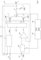
- FIG. 1 represents an electronic device comprising an embodiment of a circuit 10 configured to determine whether an input voltage is within a voltage range.
- the circuit 10 is configured to compare said input voltage to first and second voltage thresholds, different from each other.
- the device comprises a circuit 20, for example a power stage.
- the circuit 20 is an example of a circuit configured to generate the input voltage of the circuit 10.
- the circuit 20 comprises two transistors 202 and 204.
- the transistors 202 and 204 are connected, preferably connected, in series between a rail 3 for applying a supply voltage Vbat and a rail 5 for applying a reference voltage, for example the ground GND.
- one of the conduction terminals, source or drain, of the transistor 202 is connected, preferably connected, to rail 3 and the other conduction terminal, drain or source, is connected, preferably connected, to a central node 206.
- One of the conduction terminals of transistor 204, source or drain is connected, preferably connected, to node 206 and the other conduction terminal, drain or source, is connected, preferably connected, to rail 5.
- transistor 202 is a P-type field effect transistor, or PMOS
- transistor 204 is an N-type field effect transistor, or NMOS.
- Circuit 20 comprises two inputs 208 and 210.
- Input 208 receives a signal GP for controlling transistor 202.
- Input 208 is thus connected, preferably to the control terminal, or gate, of transistor 202.
- Input 210 receives a signal GN for controlling transistor 204.
- Input 210 is thus connected, preferably to the control terminal, or gate, of transistor 204.
- the node 206 is connected, preferably connected, to an input node 102 of the circuit 10.
- a current Ic is provided, via the nodes 206 and 102, at the input of the circuit 10.
- a voltage VLX, on the node 206 is provided on the input node 102 of the circuit 10.
- the node 206 is for example connected to a load, the load being for example supplied by the circuit 20.
- the circuit 20 further comprises two diodes 218 and 220.
- the diodes 218 and 220 are connected in series between the rail 3 and the rail 5. More precisely, a first terminal, anode or cathode, of the diode 220 is connected, preferably connected, to the rail 5 and a second terminal, cathode or anode, of the diode 220 is connected, preferably connected, to the node 206.
- a first terminal, anode or cathode, of the diode 218 is connected, preferably connected, to the node 206 and a second terminal, cathode or anode, of the diode 218 is connected, preferably connected to rail 3.
- the first terminals of diodes 218 and 220 are the anodes and the second terminals of diodes 218 and 220 are the cathodes.
- Node 206 is thus connected to the anode of one of the diodes and to the cathode of the other diode.
- each diode is connected, preferably connected, in parallel with one of the transistors 202 and 204.
- the anode of the diode 218 is connected, preferably connected, to the source of the transistor 202 and the cathode of the diode 218 is connected, preferably connected, to the drain of the transistor 202.
- the anode of the diode 220 is connected, preferably connected, to the source of the transistor 204 and the cathode of the diode 220 is connected, preferably connected, to the drain of the transistor 204.
- the cathode of the diode 218 is also connected, preferably connected, to the substrate of the transistor 202.
- the anode of the diode 220 is also, for example, connected, preferably connected, to the substrate of the transistor 204.
- the diodes 218 and 220 are respectively the intrinsic diodes of the transistors 202 and 204. 204.
- Circuit 10 includes input 102 and two outputs 104 and 106.
- Input 102 receives voltage VLX, which is to be compared to the voltage range, and more precisely, which is to be compared to the first and second voltage thresholds.
- the first and second thresholds are respectively the positive supply voltage Vbat of the device and a reference voltage GND, preferably ground.
- the output 104 provides a POS signal, preferably binary
- the output 106 provides a NEG signal, preferably binary.
- the circuit 10 determines that the input voltage is greater than the first threshold Vbat of the range, the NEG signal takes a first value, for example a high value.
- the voltage NEG takes a second value, for example a low value.
- the signal POS takes a first value, for example a high value. If the input voltage is higher than the second threshold, the voltage POS takes a second value, for example a low value.
- both POS and NEG signals have a low value, it means that the input voltage is between the first and second thresholds. If the NEG signal has a high value and the POS signal has a low value, the input voltage has a value greater than the first threshold. If the NEG signal has a low value and the POS signal has a high value, the input voltage has a value less than the second threshold.
- the circuit 10 comprises two transistors 108 and 110 connected in series between the rails 3 and 5. More precisely, one of the conduction terminals, source or drain, of the transistor 108 is connected, preferably connected, to a node 112. The other conduction terminal of the transistor 108, drain or source, is connected, preferably connected, to the input node 102. One of the conduction terminals of the transistor 110, source or drain, is connected, preferably connected, to the node 102. The other conduction terminal of the transistor 110, drain or source, is connected, preferably connected, to a node 114.
- transistor 110 is a P-type field effect transistor, or PMOS
- transistor 108 is an N-type field effect transistor, or NMOS.
- transistors 108 and 110 are coupled, preferably connected, to node 102, by their respective sources.
- Transistor 108 is controlled by a voltage whose value is substantially equal, preferably equal, to the second voltage threshold, here the reference voltage GND. In other words, the control terminal, or gate, of the transistor 108 is connected to the rail 5 for applying the voltage GND.
- the transistor 110 is controlled by a voltage whose value is substantially equal, preferably equal, to the first voltage threshold, here the supply voltage Vbat. In other words, the control terminal, or gate, of the transistor 110 is connected to the rail 3 for applying the voltage Vbat.
- Node 112 is connected to rail 3, preferably by a resistive element, or resistor, 116.
- Node 112 is also connected to output node 104, preferably by a circuit, or inverter, 117 configured to invert binary signals.
- circuit 117 receives a low value as input, it provides a high value as output and vice versa.
- Node 114 is connected to rail 5, preferably by a resistive element, or resistor, 118.
- Node 114 is also connected to output node 106, preferably by two circuits, or inverters, 120 and 122 in series configured to invert the binary signals.
- the resistive element 116, the transistor 108, the transistor 110 and the resistive element 118 are thus connected in series in this order between the rail 3 and the rail 5.
- Circuits 117, 120 and 122 ensure that the POS and NEG signals are binary signals having recognizable high and low values.
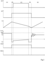
- FIG 2 represents timing diagrams illustrating the operation of the embodiment of the figure 1 . More precisely, the figure 2 represents the behavior of the control signals GN, GP, the current Ic, the voltage VLX on the node 206, and the signals POS and NEG, during an operating cycle of the circuit 20 of the figure 1 and during a part (E) of a following cycle.
- the operating cycle comprises for example four phases: a phase (A) of accumulation of energy in an inductive element not shown in figure 1 one terminal of which is connected to node 102, an intermediate phase (B), an energy restitution phase (C), and a compensation phase (D).
- the transistor 202 is on and the transistor 204 is off. This corresponds, in the embodiment of the figure 1 , to the control signal GN having a low value and to the control signal GP having a low value.
- the voltage VLX therefore has a positive value V1, lower than the value Vbat.
- the voltage VLX being lower than the control voltage of the transistor 110, that is to say the supply voltage Vbat, the gate-source voltage of the transistor 110 is positive.
- the transistor 110 therefore remains blocked during phase (A).
- the voltage on the node 114 has a low value, for example substantially equal to the reference voltage GND.
- the signal NEG, at the output of the inverters 120 and 122 therefore has a low value.
- the voltage VLX is higher than the control voltage of the transistor 108, i.e. the reference voltage GND, the gate-source voltage of the transistor 108 is negative.
- the transistor 108 therefore remains blocked during phase (A).
- the voltage on the node 112 has a high value, for example substantially equal to the voltage Vbat.
- phase (B) transistors 204 and 202 are blocked. This corresponds, in the embodiment of the figure 1 , to the GN control signal having a low value and to the GP control signal having a high value.
- the phase (B) is an intermediate phase to ensure that transistors 208 and 210 are not on simultaneously.
- node 206 is no longer supplied by rail 3.
- Current Ic therefore decreases.
- Current Ic is positive and transistors 202 and 204 are off.
- Current Ic therefore flows through diode 220.
- Voltage VLX takes a negative value V3.
- the voltage VLX being lower than the control voltage of the transistor 110, that is to say the supply voltage Vbat, the gate-source voltage of the transistor 110 is positive.
- the transistor 110 therefore remains blocked during phase (B).
- the voltage on the node 114 is a low value, for example substantially equal to the reference voltage GND.
- the signal NEG, at the output of the inverters 120 and 122 therefore has a low value.
- the voltage VLX is negative. In other words, the voltage VLX is lower than the control voltage of the transistor 108, i.e. the reference voltage GND.
- the gate-source voltage of the transistor 108 is therefore positive.
- the transistor 108 is therefore conducting during phase (B).
- the voltage on the node 112 has a low value, for example substantially equal to the voltage V3.
- the POS and NEG signals therefore indicate that the VLX voltage is below both the Vbat and GND thresholds. More precisely, the low value of the NEG signal indicates that the VLX voltage is below the Vbat threshold and is either in the range between the GND and Vbat values, or out of the range and below the GND threshold. The high value of the POS signal indicates that the VLX voltage is below the GND threshold value, and is therefore out of the range between the GND and Vbat values.
- phase (C) i.e. the energy restitution phase
- transistor 204 is on and transistor 202 is off. This corresponds, in the embodiment of the figure 1 , to the control signal GN having a high value and to the control signal GP having a high value.
- the voltage VLX increases, but remains negative.
- phase (C) the current Ic decreases, node 206 no longer being supplied by rail 3.
- the voltage VLX being lower than the control voltage of the transistor 110, that is to say the supply voltage Vbat, the gate-source voltage of the transistor 110 is positive.
- the transistor 110 therefore remains blocked during the phase (C).
- the voltage on the node 114 has a low value, for example substantially equal to the reference voltage GND.
- the signal NEG, at the output of the inverters 120 and 122 therefore has a low value.
- the voltage VLX is negative. In other words, the voltage VLX is lower than the control voltage of the transistor 108, i.e. the reference voltage GND.
- the gate-source voltage of the transistor 108 is therefore positive.
- the transistor 108 is therefore conducting during phase (B).
- the voltage on the node 112 has a low value, for example substantially equal to the voltage V3.
- phase (D) transistor 204 is blocked and transistor 202 is blocked. This corresponds, in the embodiment of the figure 1 , to the GN control signal having a low value and to the GP control signal having a high value.
- phase (B) the current Ic is positive and the transistors 202 and 204 are blocked.
- the current Ic therefore passes through the diode 220.
- the voltage VLX takes a negative value V3.
- the voltage VLX being, as in phase (B), lower than the control voltage of the transistor 110, that is to say the supply voltage Vbat, the gate-source voltage of the transistor 110 is positive.
- the transistor 110 therefore remains blocked during phase (B).
- the voltage on the node 114 has a low value, for example substantially equal to the reference voltage GND.
- the signal NEG, at the output of the inverters 120 and 122 therefore has a low value.
- the voltage VLX is negative. In other words, the voltage VLX is lower than the control voltage of the transistor 108, i.e. the reference voltage GND.
- the gate-source voltage of the transistor 108 is therefore positive.
- the transistor 108 is therefore conducting during phase (B).
- the voltage on the node 112 has a low value, for example substantially equal to the voltage V3.
- phase (D) the current Ic continues to decrease. Phase (D) ends when the current Ic reaches zero.
- Phase (D) is for example followed by a phase (E) corresponding for example to phase (A) of a following operating cycle or to a stationary phase.
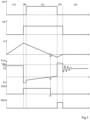
- FIG 3 represents timing diagrams illustrating the operation of the embodiment of the figure 1 . More precisely, the figure 3 represents the behavior of the control signals GN, GP, the current Ic, the voltage VLX on the node 206, and the signals POS and NEG, during an operating cycle of the circuit 20 of the figure 1 .
- the operating cycle includes, as in figure 2 , four phases: a phase (A) of energy accumulation in the inductive element, an intermediate phase (B), a phase (C) of energy restitution, and a phase (D) of compensation.
- Phases (A) and (B) are identical to phases (A) and (B) of the figure 2 . They will therefore not be described again.
- the transistor 204 is on and the transistor 202 is off. This corresponds, in the embodiment of the figure 1 , to the GN control signal having a high value and to the GP control signal having a high value.
- the voltage VLX increases during phase (C). At a time tz of phase (C), the voltage VLX reaches zero, then continues to increase. The current Ic decreases during phase (C). At time tz, the current Ic reaches zero. During phase (C), the current Ic is thus positive before time tz and negative after time tz and the voltage VLX is positive before time tz, and negative after time tz.
- the voltage VLX is lower than the first voltage threshold Vbat.
- the signal NEG maintains the low value.
- the voltage VLX is lower than the second voltage threshold GND before time tz, and higher than the second threshold after time tz.
- the signal POS takes the high value before time tz and the low value after time tz.
- phase (D) transistor 204 is blocked and transistor 202 is blocked. This corresponds, in the embodiment of the figure 1 , to the GN control signal having a low value and to the GP control signal having a high value.
- Transistors 202 and 204 being blocked, and the current Ic being negative, diode 218 becomes active.
- Voltage VLX therefore becomes higher than voltage Vbat, for example substantially equal to voltage Vbat plus voltage threshold of diode 218.
- the current Ic increases until it reaches zero.
- phase (D) is completed.
- the voltage VLX being higher than the control voltage of the transistor 110, i.e. the supply voltage Vbat, the signal NEG has a high value.
- the voltage VLX is higher than the control voltage of the transistor 108, i.e. the reference voltage GND, the signal POS has a low value.
- Phase (D) is followed by a phase (E), in which the device behaves similarly to its behavior in phase (A).
- phase (E) corresponds to a stationary phase.
- the converter 1 is a DC/DC converter, of the switching power supply type, which converts a direct current (DC) supply voltage into a direct current (DC) output voltage.
- the converter 1 is configured to provide a DC output voltage Vout.
- the converter comprises an output node 2, on which the voltage Vout is available.
- Converter 1 is supplied by a DC supply voltage Vbat. Converter 1 is then connected between a first conductive rail, or node, 3 set to voltage Vbat, and a second conductive rail, or node, 5 set to reference potential GND.
- Converter 1 is configured to provide voltage Vout at a value equal to a setpoint value. For this, converter 1 receives, on an input node 7, a DC setpoint voltage Vref referenced to potential GND, the value of which is representative of the setpoint value of voltage Vout, preferably equal to the setpoint value of voltage Vout.
- the voltages Vout, Vbat and Vref are positive.
- converter 1 is a buck converter, meaning that the setpoint value of voltage Vout is lower than the value of voltage Vbat. In other words, the value of voltage Vout is lower than that of voltage Vbat.
- the converter 1 comprises a first MOS ("metal oxide semiconductor") transistor 9, preferably a PMOS transistor (P-channel MOS transistor).
- the transistor 9 may also be an NMOS transistor associated with a bootstrap system.
- the MOS transistor 9 is connected between the rail 3 and an internal node 11.
- a first conduction terminal of the transistor 9, for example its source is connected to the rail 3, a second conduction terminal of the transistor 9, for example its drain, being connected to the node 11.
- the converter 1 further comprises a second MOS transistor 13, preferably an NMOS transistor (N-channel MOS transistor).
- the transistor 13 is connected between the node 11 and the rail 5.
- a first conduction terminal of the transistor 13, for example its source is connected to the rail 5
- a second conduction terminal of the transistor 13, for example its drain being connected to the node 11.
- the NMOS transistor 13 can be replaced by a diode or a Schottky diode.
- transistors 9 and 13 are connected in series between rails 3 and 5, and are connected to each other at internal node 11.
- Converter 1 comprises an inductive element or inductance 15.
- Inductance 15 is connected between node 11 and node 2.
- the converter 1 comprises a control circuit 17.
- the circuit 17 is configured to implement, or control, the operating cycles of the converter 1, so as to regulate the voltage Vout so that its value is equal to the set value Vref.
- Converter 1 includes an output capacitor 16 connected between node 2 and rail 5.
- this capacitor is of the order of 2.2 ⁇ F to 20 ⁇ F, or even more.
- This output capacitor acts as a filter. In other words, this output capacitor of the converter makes it possible to smooth the current present on node 2 and to store energy supplied to node 2 by the converter.
- a load is connected between node 2 and rail 5 so as to be supplied by voltage Vout.
- This load comprises for example an input capacitor between node 2 and rail 5.
- converter 1 is configured to operate in pulse frequency modulation (discontinuous conduction mode).
- Circuit 17 is then configured to start an operating cycle of converter 1 when the value of the voltage Vout is lower than the set value Vref and the two transistors 9 and 13 are in the blocked state. More particularly, at the start of each operating cycle, the circuit 17 is configured to control the setting to the passing state of the transistor 9, the transistor 13 being left in the blocked state. Energy is then accumulated in the inductor 15 and in the capacitor 16, for a first duration TPon for example constant for each operating cycle where the transistor 9 is maintained in the on state by the circuit 17, a current IL then flowing in the inductor 15.
- the circuit 17 is configured to control the setting of the transistor 9 to the off state and the setting of the transistor 13 to the on state. Energy is then restored by the inductor 15 and the capacitor 16, to the load connected at the output of the converter, for a second duration TNon for example constant for each operating cycle where the transistor 13 is maintained in the on state by the circuit 17, the current IL in the inductor decreasing.
- the circuit 17 is configured to control the setting of the transistor 13 to the off state.
- the duration TNon is determined so that the instant when the circuit 17 controls the switching off of the transistor 13 corresponds to the instant when the current IL flowing through the inductance 15 is zero.
- this is not always the case, which poses a problem.
- FIG. 5 represents timing diagrams illustrating an example of desired operation of converter 1 of the figure 4 .
- a timeline A (at the top of the figure 5 ) illustrates the evolution, as a function of time t, of the voltage Vout, in volts V
- a timing diagram B (at the bottom of the figure 5 ) illustrating the corresponding evolution, as a function of time t, of the current IL passing through the inductance 15.
- transistors 9 and 13 are in the off state, current IL is zero, and the value of voltage Vout is greater than its set value, in this example the value of voltage Vref.
- voltage Vout decreases, for example because the load connected to converter 1 consumes current and discharges the output capacitor.
- the voltage Vout becomes lower than its set value Vref. This is detected by the circuit 17 of the converter 1 which then controls the switching on of the transistor 9. The transistor 9 becomes on at time t2.
- inductance 15 has one terminal connected to node 2 and one terminal coupled to rail 3, via transistor 9.
- the current IL flowing through inductance 15 increases.
- circuit 17 controls the switching on of transistor 13 and the switching off of transistor 9.
- the current in the inductance has a maximum value ILp.
- inductance 15 has one terminal connected to node 2 and one terminal coupled to rail 5, via transistor 13. Current IL flowing through inductance 15 decreases.
- circuit 17 controls the blocking of transistor 13.
- current IL is then zero at time t4.
- this is not always the case.
- the circuit 17 implements a new operating cycle as described in relation to the successive times t2, t3 and t4.
- timing diagram A1 represents an ideal or theoretical example of the evolution of the current IL
- a timing diagram A2 represents the voltage Vout corresponding to the variations of the current IL of the timing diagram A1
- a timing diagram B1 represents an example of the real evolution of the current IL
- a timing diagram B2 represents the voltage Vout corresponding to the variations of the current IL of the timing diagram B1.
- These timing diagrams illustrate an example of operation where, for several successive operating cycles, the voltage Vout is lower than the voltage Vref at the end of each operating cycle of the converter 1. considers that the current taken on the output node is a constant current Iout.
- the current IL reaches its maximum value ILp.
- transistors 9 and 13 are switched to the off state and the on state respectively. As a result, the current decreases until a following time t32 equal to t31 + TNon.
- transistor 13 is switched to the off state at time t32, and current IL is zero at this time t32.
- transistor 9 is switched to the on state, which marks the start of a new operating cycle. Current IL then increases until a following time t33 equal to t32 + TPon.
- the current IL reaches the value ILp.
- transistors 9 and 13 are switched to the off state and the on state respectively. As a result, the current decreases until a following time t34 equal to t33 + TNo.
- transistor 13 is switched to the off state at time t34, and current IL is zero at time t34.
- the transistor 13 At time t34, the voltage Vout being lower than the voltage Vref, the transistor 13 is switched to the on state, which marks the start of a new operating cycle.
- the current IL increases until a following instant t35 equal to t34 + TPon.
- the current IL reaches the value ILp.
- transistors 9 and 13 are switched to the off state and the on state respectively. As a result, the current decreases until a following time t36 equal to t35 + TNo.
- transistor 13 is switched to the off state at time t36, and current IL is zero at time t36.
- Timing diagrams B1 and B2 illustrate a corresponding example of real operation of converter 1.
- the practical case is considered where transistor 13 is not immediately switched to the off state at the end of the time TNon which has elapsed since its last switching to the on state.
- current IL reaches its maximum value ILp. Furthermore, transistors 9 and 13 are switched to the off state and the on state respectively. As a result, the current decreases until a subsequent time t42 equal to t41 + TNon. The current is zero at time t42. However, the switching of transistor 13 to the off state is only effective at time t43 after time t42. Thus, between times t42 and t43, current IL is negative and decreases. In other words, the current flows in inductance 15 from node 11 to node 2 before time t42, is zero at time t42, and flows in inductance 15, from node 2 to node 11 after time t42.
- transistor 9 is switched to the on state at time t43, which marks the start of a new operating cycle. Current IL then increases until a following time t44 equal to t43 + TPon.
- current IL reaches a value ILp', lower than the maximum value ILp because duration TPon is constant at each cycle. Furthermore, transistors 9 and 13 are switched to the off state and the on state respectively. As a result, current IL decreases until a following time t46 equal to t44 + TNon, current IL being zero at a time t45 between times t44 and t46. Furthermore, switching of transistor 13 to the off state is only effective at a time t47 after time t46. Thus, between times t45 and t47, current IL is negative and decreases to a lower value (or greater in absolute value) than that reached at time t43.
- the transistor 9 is switched to the on state at time t47, which marks the start of a new cycle of operation.
- the current IL then increases until a following instant t48 equal to t47 + TPon.
- current IL reaches a value ILp'', lower than value ILp'. Furthermore, transistors 9 and 13 are switched to the off state and the on state respectively. As a result, current IL decreases until a subsequent time t50 equal to t48 + TNon, current IL becoming zero at a time t49 between times t48 and t50. Furthermore, switching of transistor 13 to the off state is only effective at a time t51 subsequent to time t50. Thus, between times t49 and t51, current IL is negative and decreases to a lower value (or greater in absolute value) than that reached at time t47.
- the value of the current supplied to the load decreases from one cycle to the next, which has a negative impact on the power supply to the load.
- the maximum value of the current IL could decrease to infinity, but, in practice, the transistor 13 can, in some cases, be destroyed, or damaged, before that by negative values of the current IL. that transistor 13 is not able to circulate between its conduction terminals.
- the transistor 13 is switched to the blocked state while the current IL is not zero and is still positive.
- the current IL increases from an increasingly higher value, from which it follows that the current IL reaches an increasingly higher maximum value, and that the operating cycle ends with an increasingly higher non-zero and positive value of the current IL.
- This operation is less troublesome than that described in relation to the timing diagrams B1 and B2 because, after several operating cycles, the voltage Vout will have returned to its set value Vref. Thus, the following operating cycle will not be immediately implemented which will allow time for the current IL to cancel out.
- FIG 7 represents an example of application of the embodiment of circuit 10 of the figure 1 , in a DC/DC voltage converter.
- the converter of the figure 7 includes the elements described in relation to the figure 4 , circuit 17 being more detailed.
- the converter comprises transistors 9 and 13, inductance 15 and capacitor 16, described in relation to the figure 4 .
- Transistors 9 and 13 are, like transistors 202 and 204 of the figure 1 , connected, preferably connected, in series between the rail 3 for applying a supply voltage Vbat and the rail 5 for applying a reference voltage, for example the ground GND.
- one of the conduction terminals, source or drain, of the transistor 9 is connected, preferably connected, to the rail 3 and the other conduction terminal, drain or source, is connected, preferably connected, to the central node 11.
- One of the conduction terminals of the transistor 13, source or drain is connected, preferably connected, to the node 11 and the other conduction terminal, drain or source, is connected, preferably connected, to the rail 5.
- transistor 9 is a P-type field effect transistor, or PMOS
- transistor 13 is an N-type field effect transistor, or NMOS.
- Each of transistors 9 and 13 includes an intrinsic diode not shown.
- the intrinsic diodes not shown are, like diodes 218 and 220 of the figure 1 , connected in series between rail 3 and rail 5. More precisely, a first terminal, anode or cathode, of the intrinsic diode of transistor 13 is connected, preferably connected, to rail 5 and a second terminal, cathode or anode, of said diode is connected, preferably connected, to rail 5. preferably connected, to node 11. A first terminal, anode or cathode, of the intrinsic diode of transistor 9 is connected, preferably connected, to node 11 and a second terminal, cathode or anode, of said diode is connected, preferably connected, to rail 3.
- the first terminals of the intrinsic diodes are the anodes and the second terminals of the intrinsic diodes are the cathodes.
- Node 11 is thus connected to the anode of one of the diodes and to the cathode of the other diode.
- the converter comprises a circuit 180 for generating the control signals GP, GN, a circuit 182 for supplying a signal PWN determining the durations TPon and TNon, a circuit 184 configured to determine the start times of each operating cycle and a circuit 186 generating a variable voltage.
- the circuit 180 comprises first and second outputs 180a and 180b, respectively connected, preferably connected, to the outputs 175 and 176 of the circuit 17.
- the circuit 180 generates, on the first output 180a, the signal GP for controlling the transistor 9, and on the second output 180b the signal GN for controlling the transistor 13.
- the circuit 180 comprises an input 180c connected, preferably connected, to an output of the circuit 182.
- the circuit 182 provides on this output the signal PWN determining the durations TPon and TNon, and thus determining the durations of the energy accumulation and energy restitution phases.
- the circuit 182 comprises two inputs 182a and 182b, respectively connected, preferably connected, to the inputs 171 and 172 of the circuit 17.
- the circuit 182 therefore generates the signal PWN according to the value of the voltage Vout, received on the input 172, and the setpoint voltage Vref, received on the input 171, and more precisely, according to the difference between these values.
- the voltage Vout is lower than the voltage Vref
- the TPon duration is increased and the TNon duration is decreased.
- the Vout voltage is greater than the Vref voltage
- the TNon duration is increased and the TPon duration is decreased.
- the converter comprises the circuit 184 configured to determine the start times of each operating cycle. More precisely, the circuit 184 is configured to determine the time at which the current Ic reaches the zero value, i.e. the end of an operating cycle. In practice, this corresponds to the detection of a crossing of the voltage VLX with the zero value.
- the circuit 184 comprises an output connected, preferably connected, to the circuit 180 so as to provide this information by a signal S taking a high value when the current Ic reaches the zero value.
- Circuit 184 is for example a zero crossing detect circuit ("Zero Crossing Detect" in English, or ZCD). Circuit 184 includes a comparator.
- the comparator of circuit 184 is subject to the faults mentioned in relation to the Figure 6B . More specifically, the propagation delay and the offset of the input voltages of said comparator result in comparison defects, as described in relation to the Figure 6B .
- Circuit 184 is connected as input to rail 5, providing the reference voltage GND, and to node 11, providing the voltage VLX.
- Circuit 184 is connected to rail 5 by circuit 186 configured to modify the value to which voltage VLX is compared, so as to compensate for propagation delay and comparator offset of circuit 184.
- circuit 186 is a variable voltage source.
- the output voltage of circuit 186 i.e. the input voltage of circuit 184 which is compared with voltage VLX, may be different from zero.
- Circuit 184 does not compare voltage VLX with the zero value but with the output value of circuit 186.
- the output value of circuit 186 is for example modified at each operating cycle.
- circuit 186 receives a signal d.
- Signal d is generated by a circuit assembly comprising a circuit 10 and a circuit 190.
- Circuit 10 is therefore connected, preferably connected, at the input to node 11.
- Circuit 10 comprises two outputs on which the signals POS and NEG are generated.
- the circuit 190 is connected, preferably connected, at the input, to the outputs of the circuit 10 and therefore receives the signals POS and NEG at the input.
- the circuit 190 determines the sign of the current Ic during the phase (D) and generates the signal d controlling the modification of the output value of the circuit 186.
- the voltage modification of the circuit 186 is therefore dependent on the sign of the current Ic during the phase (D) and preferably independent of the sign of the current during the other phases.
- FIG 8 represents timing diagrams illustrating an example of operation of the embodiment of the figure 7 .
- There figure 8 represents two operating cycles of the converter, separated from each other by a shutdown phase.
- transistors 9 and 13 are blocked. This corresponds to signals GN and GP having respectively a low value and a high value.
- the current Ic is zero and the voltage VLX has a value substantially equal to a voltage V2, positive and lower than the voltage Vbat.
- the signal S preferably binary, has for example a low value.
- Time t60 a phase (A) of an operating cycle begins.
- Time t60 therefore corresponds to the end of a phase (E) and the beginning of a phase (A).
- transistor 9 turns on.
- the value of the control signal GP takes the other binary value, here the low value.
- Node 11 is therefore supplied by rail 3.
- the voltage on the node takes the value V1, slightly lower than the value Vbat but higher than the value V2, and the current Ic increases.
- phase (A) ends and phase (B) begins.
- the duration of phase (A) corresponds to the duration TPon.
- phase (B) is an intermediate phase ensuring that transistors 9 and 13 are not on simultaneously. During phase (B), node 11 is no longer supplied by rail 3. Current Ic therefore decreases.
- the current Ic is positive and the transistors 202 and 204 are blocked. The current Ic therefore passes through the diode 220.
- the voltage VLX takes a negative value V3.
- phase (B) As described in relation to the figures 2 And 3 , the POS signal takes a high value. However, the circuit 190 does not take into account the POS and NEG signals during phase (B).
- phase (B) ends and phase (C) begins.
- Transistor 13 is on and transistor 9 is off. This corresponds, in the embodiment of the figure 7 , to the GN control signal having a high value and to the control signal GP having a high value.
- the voltage VLX increases and the current Ic flowing through the inductance 15 decreases, the node 11 no longer being supplied by the rail 3.
- the circuit 184 has a propagation delay of a value D.
- the output S of the circuit 184 only takes a high value, indicating the crossing of the current Ic with the zero value, at a time t66 separated from the time tz1 by the duration D. Between the time tz1 and the time t66, the current Ic becomes negative.
- phase (C) is thus finished and phase (D) begins.
- phase (D) transistors 9 and 13 are blocked. This corresponds, in the embodiment of the figure 7 , to the GN control signal having a low value and to the GP control signal having a high value.
- Transistors 9 and 13 being blocked, and the current Ic being negative, the intrinsic diode of transistor 9 becomes active.
- the voltage VLX therefore becomes higher than the voltage Vbat, for example substantially equal to the voltage Vbat plus the threshold voltage of the diode.
- the current Ic increases until it reaches zero at a time t68.
- the diode is no longer conducting and phase (D) is terminated.
- phase (E) is followed by a second operating cycle comprising a phase (A) between times t70 and t72, a phase (B) between time t72 and a time t74, a phase (C) between time t74 and time t76, and a phase (D) between time t76 and time t78.
- the second operating cycle differs from the first cycle in that, before phase (C), for example during phase (A), circuit 190 supplies a signal d to circuit 186 so as to modify the value of the output signal of circuit 186.
- the value of the output of circuit 186 is modified so as to be equal to a value V4 lower than the value of the reference voltage, here ground.
- circuit 184 compares voltage VLX to value V4.
- Value V4 is reached here, at time tz2, earlier than zero value is reached.
- Phase (C) ends time D after time tz2. The negative value reached by current Ic at the end of phase (C) is closer to zero than the value reached by current Ic at the end of the previous phase (C).
- An advantage of the described embodiments is that it is possible to compare a voltage at two thresholds by a simple circuit.
Landscapes
- Engineering & Computer Science (AREA)
- Power Engineering (AREA)
- Physics & Mathematics (AREA)
- General Physics & Mathematics (AREA)
- Dc-Dc Converters (AREA)
- Electromagnetism (AREA)
- Radar, Positioning & Navigation (AREA)
- Automation & Control Theory (AREA)
- Measurement Of Current Or Voltage (AREA)
- Manipulation Of Pulses (AREA)
Claims (9)
- Elektronische Vorrichtung, die Folgendes aufweist:- eine erste Schaltung (20) mit einem ersten (202, 9) und einem zweiten (204, 13) Transistor, die zwischen einem Knoten (3) zum Anlegen einer Versorgungsspannung (Vbat) und einem Knoten (5) zum Anlegen einer Referenzspannung (GND) in Reihe geschaltet sind, wobei der erste und der zweite Transistor über einen ersten Knoten (206, 11) miteinander verbunden sind; und- eine zweite Schaltung (10), die konfiguriert ist zum Vergleichen einer ersten Spannung (VLX) am ersten Knoten mit ersten (Vbat) und zweiten (GND) Spannungsschwellenwerten,wobei die zweite Schaltung einen dritten (108) und einen vierten (110) Transistor aufweist, die zwischen einem zweiten (112) und einem dritten (114) Knoten in Reihe geschaltet sind, wobei der dritte und der vierte Transistor über einen vierten Knoten (102), der mit dem ersten Knoten verbunden ist, miteinander verbunden sind, und wobei der zweite Knoten (112) über ein erstes Widerstandselement (116) mit dem Knoten (3) zum Anlegen der Versorgungsspannung (Vbat) verbunden ist, und wobei der dritte Knoten (114) mit dem Knoten (5) zum Anlegen der Referenzspannung (GND) über ein zweites Widerstandselement (118) verbunden ist, wobei der Steueranschluss des dritten Transistors (108) mit einem Knoten zum Anlegen des zweiten Spannungsschwellenwerts verbunden ist, und der Steueranschluss des vierten Transistors (110) mit einem Knoten zum Anlegen des ersten Spannungsschwellenwerts verbunden ist, wobei die zweite Schaltung (10) Folgendes aufweist:- einen ersten Ausgangsknoten (106), der konfiguriert ist zum Liefern eines Signals (NEG), das einen ersten Wert annimmt, wenn die erste Spannung (VLX) höher als der erste Spannungsschwellenwert (Vbat) ist, und einen zweiten Wert annimmt, wenn die erste Spannung (VLX) niedriger als der erste Spannungsschwellenwert (Vbat) ist, wobei der erste Ausgangsknoten (106) mit dem dritten Knoten (114) verbunden ist; und- einen zweiten Ausgangsknoten (104), der konfiguriert ist zum Liefern eines Signals (POS) liefert, das einen ersten Wert annimmt, wenn die erste Spannung (VLX) niedriger als der zweite Spannungsschwellenwert (GND) ist, und einen zweiten Wert annimmt, wenn die erste Spannung höher als der zweite Spannungsschwellenwert ist, wobei der zweite Ausgangsknoten (104) mit dem zweiten Knoten (112) verbunden ist.
- Verfahren zum Steuern eines elektronischen Geräts, das Folgendes aufweist:- eine erste Schaltung (20) mit einem ersten (202, 9) und einem zweiten (204, 13) Transistor, die zwischen einem Knoten (3) zum Anlegen einer Versorgungsspannung (Vbat) und einem Knoten (5) zum Anlegen einer Referenzspannung (GND) in Reihe geschaltet sind, wobei der erste und der zweite Transistor über einen ersten Knoten (206, 11) miteinander verbunden sind; und- eine zweite Schaltung (10),wobei die zweite Schaltung konfiguriert ist zum Vergleichen einer ersten Spannung (VLX) am ersten Knoten mit ersten (Vbat) und zweiten (GND) Spannungsschwellenwerten,wobei die zweite Schaltung einen dritten (108) und einen vierten (110) Transistor aufweist, die zwischen einem zweiten (112) und einem dritten (114) Knoten in Reihe geschaltet sind, wobei der dritte und der vierte Transistor über einen vierten Knoten (102), der mit dem ersten Knoten verbunden ist, miteinander verbunden sind, und wobei der zweite Knoten (112) über ein erstes Widerstandselement (116) mit dem Knoten (3) zum Anlegen der Versorgungsspannung (Vbat) verbunden ist, und wobei der dritte Knoten (114) mit dem Knoten (5) zum Anlegen der Referenzspannung (GND) über ein zweites Widerstandselement (118) verbunden ist, wobei der Steueranschluss des dritten Transistors (108) mit einem Knoten zum Anlegen des zweiten Spannungsschwellenwerts verbunden ist, und der Steueranschluss des vierten Transistors (110) mit einem Knoten zum Anlegen des ersten Spannungsschwellenwerts verbunden ist, wobei die zweite Schaltung (10) Folgendes aufweist:- einen ersten Ausgangsknoten (106), der ein Signal (NEG) liefert, das einen ersten Wert annimmt, wenn die erste Spannung (VLX) höher als der erste Spannungsschwellenwert (Vbat) ist, und einen zweiten Wert annimmt, wenn die erste Spannung (VLX) niedriger als der erste Spannungsschwellenwert (Vbat) ist, wobei der erste Ausgangsknoten (106) mit dem dritten Knoten (114) verbunden ist; und- einen zweiten Ausgangsknoten (104), der ein Signal (POS) liefert, das einen ersten Wert annimmt, wenn die erste Spannung (VLX) niedriger als die zweite Spannungsschwelle (GND) ist, und einen zweiten Wert annimmt, wenn die erste Spannung höher als die zweite Spannungsschwelle ist, wobei der zweite Ausgangsknoten (104) mit dem zweiten Knoten (112) verbunden ist.
- Vorrichtung nach Anspruch 1 oder Verfahren nach Anspruch 2, wobei die erste Spannungsschwelle die Versorgungsspannung (Vbat) und die zweite Spannungsschwelle die Referenzspannung (GND) ist.
- Vorrichtung nach Anspruch 1 oder 3 oder Verfahren nach Anspruch 2 oder 3, wobei der erste Ausgangsknoten (106) über zwei Inverterschaltungen (120, 122) mit dem zweiten Knoten (114) verbunden ist und der zweite Ausgangsknoten (104) über eine Inverterschaltung (117) mit dem zweiten Knoten (112) verbunden ist.
- Vorrichtung nach einem der Ansprüche 1, 3 oder 4 oder Verfahren nach einem der Ansprüche 2 bis 4, wobei der erste Transistor (202) parallel zu einer ersten Diode (218) geschaltet ist, der zweite Transistor (204) parallel zu einer zweiten Diode (220) geschaltet ist, wobei die Anode der ersten Diode und die Kathode der zweiten Diode mit dem ersten Knoten (206) verbunden sind.
- Vorrichtung nach einem der Ansprüche 1 oder 3 bis 5 oder Verfahren nach einem der Ansprüche 2 bis 5, wobei die Vorrichtung ein Schaltnetzteil ist.
- Vorrichtung oder Verfahren nach Anspruch 6, wobei die Vorrichtung eine dritte Schaltung (184) aufweist, die konfiguriert ist zum Vergleichen einer ersten Spannung (VLX) mit einer zweiten Spannung, wobei die zweite Spannung variabel ist und von den Signalen an den ersten und zweiten Ausgangsknoten abhängt.
- Vorrichtung nach einem der Ansprüche 1 oder 3 bis 7 oder Verfahren nach einem der Ansprüche 2 bis 7, wobei die Vorrichtung eine vierte Schaltung aufweist, die konfiguriert ist zum Steuern der ersten und zweiten Transistoren so, dass jeder Betriebszyklus aufeinanderfolgend aufweist:- eine erste Phase, in der der erste Transistor eingeschaltet und der zweite Transistor ausgeschaltet ist;- eine zweite Phase, in der der erste und der zweite Transistor ausgeschaltet sind;- eine dritte Phase, in der der erste Transistor ausgeschaltet ist und der zweite Transistor eingeschaltet ist; und- eine vierte Phase, in der der erste und der zweite Transistor ausgeschaltet sind.
- Vorrichtung oder Verfahren nach den Ansprüchen 7 und 8, wobei die Änderung der zweiten Spannung von den Signalen an den ersten und zweiten Ausgangsknoten während der vierten Phase abhängt.
Applications Claiming Priority (1)
| Application Number | Priority Date | Filing Date | Title |
|---|---|---|---|
| FR2008088A FR3113139B1 (fr) | 2020-07-30 | 2020-07-30 | Comparateur de tension |
Publications (2)
| Publication Number | Publication Date |
|---|---|
| EP3945673A1 EP3945673A1 (de) | 2022-02-02 |
| EP3945673B1 true EP3945673B1 (de) | 2024-10-09 |
Family
ID=73013685
Family Applications (1)
| Application Number | Title | Priority Date | Filing Date |
|---|---|---|---|
| EP21187089.4A Active EP3945673B1 (de) | 2020-07-30 | 2021-07-22 | Spannungsvergleicher |
Country Status (4)
| Country | Link |
|---|---|
| US (1) | US11736018B2 (de) |
| EP (1) | EP3945673B1 (de) |
| CN (2) | CN216904672U (de) |
| FR (1) | FR3113139B1 (de) |
Families Citing this family (4)
| Publication number | Priority date | Publication date | Assignee | Title |
|---|---|---|---|---|
| FR3113139B1 (fr) * | 2020-07-30 | 2022-11-25 | St Microelectronics Rousset | Comparateur de tension |
| CN115149821A (zh) * | 2021-03-31 | 2022-10-04 | 意法半导体(鲁塞)公司 | 电压转换器 |
| FR3121556B1 (fr) * | 2021-03-31 | 2023-03-10 | St Microelectronics Rousset | Convertisseur de tension |
| FR3146558A1 (fr) * | 2023-03-10 | 2024-09-13 | Stmicroelectronics International N.V. | Procédé de calibration d'un convertisseur à découpage |
Citations (1)
| Publication number | Priority date | Publication date | Assignee | Title |
|---|---|---|---|---|
| US8692534B2 (en) * | 2007-12-17 | 2014-04-08 | St-Ericsson Sa | Current measuring device |
Family Cites Families (14)
| Publication number | Priority date | Publication date | Assignee | Title |
|---|---|---|---|---|
| JP4360010B2 (ja) | 2000-04-27 | 2009-11-11 | ソニー株式会社 | 並列型アナログ−ディジタル変換器 |
| JP4685531B2 (ja) * | 2005-07-11 | 2011-05-18 | ローム株式会社 | 降圧型スイッチングレギュレータおよびその制御回路ならびにそれを用いた電子機器 |
| GB0912745D0 (en) * | 2009-07-22 | 2009-08-26 | Wolfson Microelectronics Plc | Improvements relating to DC-DC converters |
| EP2302776B1 (de) * | 2009-09-29 | 2012-10-31 | STMicroelectronics Srl | Spannungsdetektor für Halbbrückenschaltung |
| US8278897B2 (en) * | 2009-12-17 | 2012-10-02 | Semiconductor Components Industries, Llc | Power supply converter and method |
| US8508207B2 (en) * | 2010-10-29 | 2013-08-13 | R2 Semiconductor | Controlling a skew time of switches of a switching regulator |
| EP2940847A1 (de) * | 2014-04-30 | 2015-11-04 | Dialog Semiconductor GmbH | Verfahren und Vorrichtung für eine adaptive Schwelle eines Nulldurchgangkomparators, basierend auf dem Strom in den parasitären bipolaren Transistoren |
| US10381927B2 (en) * | 2017-07-17 | 2019-08-13 | Dialog Semiconductor (Uk) Limited | Pulse-frequency modulation constant on-time with peak-current servo |
| US10749436B2 (en) * | 2018-01-09 | 2020-08-18 | Dialog Semiconductor (Uk) Limited | Zero cross comparator |
| TWI686045B (zh) * | 2019-02-13 | 2020-02-21 | 新唐科技股份有限公司 | 零電流偵測系統 |
| CN110138209B (zh) * | 2019-05-13 | 2021-08-06 | 矽力杰半导体技术(杭州)有限公司 | 开关电源的模式切换电路和模式切换方法 |
| FR3102900B1 (fr) * | 2019-11-05 | 2023-10-27 | St Microelectronics Grenoble 2 | Convertisseur de tension |
| FR3113139B1 (fr) * | 2020-07-30 | 2022-11-25 | St Microelectronics Rousset | Comparateur de tension |
| FR3121556B1 (fr) * | 2021-03-31 | 2023-03-10 | St Microelectronics Rousset | Convertisseur de tension |
-
2020
- 2020-07-30 FR FR2008088A patent/FR3113139B1/fr active Active
-
2021
- 2021-07-08 US US17/370,609 patent/US11736018B2/en active Active
- 2021-07-22 EP EP21187089.4A patent/EP3945673B1/de active Active
- 2021-07-29 CN CN202121743945.4U patent/CN216904672U/zh not_active Withdrawn - After Issue
- 2021-07-29 CN CN202110863231.5A patent/CN114070058B/zh active Active
Patent Citations (1)
| Publication number | Priority date | Publication date | Assignee | Title |
|---|---|---|---|---|
| US8692534B2 (en) * | 2007-12-17 | 2014-04-08 | St-Ericsson Sa | Current measuring device |
Also Published As
| Publication number | Publication date |
|---|---|
| CN216904672U (zh) | 2022-07-05 |
| EP3945673A1 (de) | 2022-02-02 |
| US20220038003A1 (en) | 2022-02-03 |
| FR3113139A1 (fr) | 2022-02-04 |
| US11736018B2 (en) | 2023-08-22 |
| CN114070058B (zh) | 2025-10-28 |
| FR3113139B1 (fr) | 2022-11-25 |
| CN114070058A (zh) | 2022-02-18 |
Similar Documents
| Publication | Publication Date | Title |
|---|---|---|
| EP3945673B1 (de) | Spannungsvergleicher | |
| EP4037170B1 (de) | Synchronisierung einer elektronischen vorrichtung | |
| EP3382875A1 (de) | Gleichstrom-gleichstrom-wandler | |
| EP3945674A1 (de) | Spannungswandler | |
| EP3771082A1 (de) | Schaltnetzteil | |
| EP3499699A1 (de) | Stromzuführung mit partitionierung, und ihr steuerverfahren | |
| FR3102620A1 (fr) | Convertisseur de tension | |
| FR3102900A1 (fr) | Convertisseur de tension | |
| EP4068606B1 (de) | Spannungswandler | |
| EP4037174B1 (de) | Synchronisierung einer elektronischen vorrichtung | |
| EP2932588B1 (de) | Schaltung zum vergleichen einer spannung mit einem schwellenwert und umwandlung von elektrischer energie | |
| EP4044415A1 (de) | Starten einer stromzuführung mit partitionierung | |
| EP4102701A1 (de) | Leistungswandler | |
| EP3576268B1 (de) | Elektronischer stromkreis | |
| FR3102621A1 (fr) | Comparateur de tension | |
| EP4092892A1 (de) | Schaltnetzteil | |
| EP3771080A1 (de) | Starten eine stromzuführung mit partitionierung | |
| EP3633487A1 (de) | Schaltwandler | |
| FR3113140A1 (fr) | Convertisseur de tension | |
| EP4346077B1 (de) | Transistorsteuerung | |
| EP4089906A1 (de) | Dc-dc-abwärtswandler mit abschaltfunktion | |
| FR3113142A1 (fr) | Convertisseur de tension | |
| FR3103581A1 (fr) | Pompe de charge | |
| FR2758021A1 (fr) | Circuit elevateur de tension | |
| EP1710913B1 (de) | Getakte Stromversorgung |
Legal Events
| Date | Code | Title | Description |
|---|---|---|---|
| PUAI | Public reference made under article 153(3) epc to a published international application that has entered the european phase |
Free format text: ORIGINAL CODE: 0009012 |
|
| STAA | Information on the status of an ep patent application or granted ep patent |
Free format text: STATUS: REQUEST FOR EXAMINATION WAS MADE |
|
| 17P | Request for examination filed |
Effective date: 20210722 |
|
| AK | Designated contracting states |
Kind code of ref document: A1 Designated state(s): AL AT BE BG CH CY CZ DE DK EE ES FI FR GB GR HR HU IE IS IT LI LT LU LV MC MK MT NL NO PL PT RO RS SE SI SK SM TR |
|
| STAA | Information on the status of an ep patent application or granted ep patent |
Free format text: STATUS: EXAMINATION IS IN PROGRESS |
|
| 17Q | First examination report despatched |
Effective date: 20221201 |
|
| GRAP | Despatch of communication of intention to grant a patent |
Free format text: ORIGINAL CODE: EPIDOSNIGR1 |
|
| STAA | Information on the status of an ep patent application or granted ep patent |
Free format text: STATUS: GRANT OF PATENT IS INTENDED |
|
| GRAJ | Information related to disapproval of communication of intention to grant by the applicant or resumption of examination proceedings by the epo deleted |
Free format text: ORIGINAL CODE: EPIDOSDIGR1 |
|
| STAA | Information on the status of an ep patent application or granted ep patent |
Free format text: STATUS: EXAMINATION IS IN PROGRESS |
|
| GRAP | Despatch of communication of intention to grant a patent |
Free format text: ORIGINAL CODE: EPIDOSNIGR1 |
|
| STAA | Information on the status of an ep patent application or granted ep patent |
Free format text: STATUS: GRANT OF PATENT IS INTENDED |
|
| INTG | Intention to grant announced |
Effective date: 20240503 |
|
| INTG | Intention to grant announced |
Effective date: 20240527 |
|
| GRAS | Grant fee paid |
Free format text: ORIGINAL CODE: EPIDOSNIGR3 |
|
| GRAA | (expected) grant |
Free format text: ORIGINAL CODE: 0009210 |
|
| STAA | Information on the status of an ep patent application or granted ep patent |
Free format text: STATUS: THE PATENT HAS BEEN GRANTED |
|
| AK | Designated contracting states |
Kind code of ref document: B1 Designated state(s): AL AT BE BG CH CY CZ DE DK EE ES FI FR GB GR HR HU IE IS IT LI LT LU LV MC MK MT NL NO PL PT RO RS SE SI SK SM TR |
|
| REG | Reference to a national code |
Ref country code: CH Ref legal event code: EP |
|
| REG | Reference to a national code |
Ref country code: IE Ref legal event code: FG4D Free format text: LANGUAGE OF EP DOCUMENT: FRENCH |
|
| REG | Reference to a national code |
Ref country code: DE Ref legal event code: R096 Ref document number: 602021019815 Country of ref document: DE |
|
| REG | Reference to a national code |
Ref country code: LT Ref legal event code: MG9D |
|
| REG | Reference to a national code |
Ref country code: NL Ref legal event code: MP Effective date: 20241009 |
|
| REG | Reference to a national code |
Ref country code: AT Ref legal event code: MK05 Ref document number: 1731675 Country of ref document: AT Kind code of ref document: T Effective date: 20241009 |
|
| PG25 | Lapsed in a contracting state [announced via postgrant information from national office to epo] |
Ref country code: NL Free format text: LAPSE BECAUSE OF FAILURE TO SUBMIT A TRANSLATION OF THE DESCRIPTION OR TO PAY THE FEE WITHIN THE PRESCRIBED TIME-LIMIT Effective date: 20241009 |
|
| PG25 | Lapsed in a contracting state [announced via postgrant information from national office to epo] |
Ref country code: NL Free format text: LAPSE BECAUSE OF FAILURE TO SUBMIT A TRANSLATION OF THE DESCRIPTION OR TO PAY THE FEE WITHIN THE PRESCRIBED TIME-LIMIT Effective date: 20241009 |
|
| PG25 | Lapsed in a contracting state [announced via postgrant information from national office to epo] |
Ref country code: PT Free format text: LAPSE BECAUSE OF FAILURE TO SUBMIT A TRANSLATION OF THE DESCRIPTION OR TO PAY THE FEE WITHIN THE PRESCRIBED TIME-LIMIT Effective date: 20250210 Ref country code: HR Free format text: LAPSE BECAUSE OF FAILURE TO SUBMIT A TRANSLATION OF THE DESCRIPTION OR TO PAY THE FEE WITHIN THE PRESCRIBED TIME-LIMIT Effective date: 20241009 Ref country code: IS Free format text: LAPSE BECAUSE OF FAILURE TO SUBMIT A TRANSLATION OF THE DESCRIPTION OR TO PAY THE FEE WITHIN THE PRESCRIBED TIME-LIMIT Effective date: 20250209 |
|
| PG25 | Lapsed in a contracting state [announced via postgrant information from national office to epo] |
Ref country code: FI Free format text: LAPSE BECAUSE OF FAILURE TO SUBMIT A TRANSLATION OF THE DESCRIPTION OR TO PAY THE FEE WITHIN THE PRESCRIBED TIME-LIMIT Effective date: 20241009 |
|
| PG25 | Lapsed in a contracting state [announced via postgrant information from national office to epo] |
Ref country code: BG Free format text: LAPSE BECAUSE OF FAILURE TO SUBMIT A TRANSLATION OF THE DESCRIPTION OR TO PAY THE FEE WITHIN THE PRESCRIBED TIME-LIMIT Effective date: 20241009 |
|
| PG25 | Lapsed in a contracting state [announced via postgrant information from national office to epo] |
Ref country code: ES Free format text: LAPSE BECAUSE OF FAILURE TO SUBMIT A TRANSLATION OF THE DESCRIPTION OR TO PAY THE FEE WITHIN THE PRESCRIBED TIME-LIMIT Effective date: 20241009 |
|
| PG25 | Lapsed in a contracting state [announced via postgrant information from national office to epo] |
Ref country code: NO Free format text: LAPSE BECAUSE OF FAILURE TO SUBMIT A TRANSLATION OF THE DESCRIPTION OR TO PAY THE FEE WITHIN THE PRESCRIBED TIME-LIMIT Effective date: 20250109 |
|
| PG25 | Lapsed in a contracting state [announced via postgrant information from national office to epo] |
Ref country code: GR Free format text: LAPSE BECAUSE OF FAILURE TO SUBMIT A TRANSLATION OF THE DESCRIPTION OR TO PAY THE FEE WITHIN THE PRESCRIBED TIME-LIMIT Effective date: 20250110 Ref country code: LV Free format text: LAPSE BECAUSE OF FAILURE TO SUBMIT A TRANSLATION OF THE DESCRIPTION OR TO PAY THE FEE WITHIN THE PRESCRIBED TIME-LIMIT Effective date: 20241009 Ref country code: AT Free format text: LAPSE BECAUSE OF FAILURE TO SUBMIT A TRANSLATION OF THE DESCRIPTION OR TO PAY THE FEE WITHIN THE PRESCRIBED TIME-LIMIT Effective date: 20241009 |
|
| PG25 | Lapsed in a contracting state [announced via postgrant information from national office to epo] |
Ref country code: PL Free format text: LAPSE BECAUSE OF FAILURE TO SUBMIT A TRANSLATION OF THE DESCRIPTION OR TO PAY THE FEE WITHIN THE PRESCRIBED TIME-LIMIT Effective date: 20241009 |
|
| PG25 | Lapsed in a contracting state [announced via postgrant information from national office to epo] |
Ref country code: RS Free format text: LAPSE BECAUSE OF FAILURE TO SUBMIT A TRANSLATION OF THE DESCRIPTION OR TO PAY THE FEE WITHIN THE PRESCRIBED TIME-LIMIT Effective date: 20250109 |
|
| PG25 | Lapsed in a contracting state [announced via postgrant information from national office to epo] |
Ref country code: SM Free format text: LAPSE BECAUSE OF FAILURE TO SUBMIT A TRANSLATION OF THE DESCRIPTION OR TO PAY THE FEE WITHIN THE PRESCRIBED TIME-LIMIT Effective date: 20241009 |
|
| PG25 | Lapsed in a contracting state [announced via postgrant information from national office to epo] |
Ref country code: DK Free format text: LAPSE BECAUSE OF FAILURE TO SUBMIT A TRANSLATION OF THE DESCRIPTION OR TO PAY THE FEE WITHIN THE PRESCRIBED TIME-LIMIT Effective date: 20241009 |
|
| REG | Reference to a national code |
Ref country code: DE Ref legal event code: R097 Ref document number: 602021019815 Country of ref document: DE |
|
| PG25 | Lapsed in a contracting state [announced via postgrant information from national office to epo] |
Ref country code: EE Free format text: LAPSE BECAUSE OF FAILURE TO SUBMIT A TRANSLATION OF THE DESCRIPTION OR TO PAY THE FEE WITHIN THE PRESCRIBED TIME-LIMIT Effective date: 20241009 |
|
| PG25 | Lapsed in a contracting state [announced via postgrant information from national office to epo] |
Ref country code: RO Free format text: LAPSE BECAUSE OF FAILURE TO SUBMIT A TRANSLATION OF THE DESCRIPTION OR TO PAY THE FEE WITHIN THE PRESCRIBED TIME-LIMIT Effective date: 20241009 |
|
| PG25 | Lapsed in a contracting state [announced via postgrant information from national office to epo] |
Ref country code: SK Free format text: LAPSE BECAUSE OF FAILURE TO SUBMIT A TRANSLATION OF THE DESCRIPTION OR TO PAY THE FEE WITHIN THE PRESCRIBED TIME-LIMIT Effective date: 20241009 |
|
| PG25 | Lapsed in a contracting state [announced via postgrant information from national office to epo] |
Ref country code: CZ Free format text: LAPSE BECAUSE OF FAILURE TO SUBMIT A TRANSLATION OF THE DESCRIPTION OR TO PAY THE FEE WITHIN THE PRESCRIBED TIME-LIMIT Effective date: 20241009 |
|
| PG25 | Lapsed in a contracting state [announced via postgrant information from national office to epo] |
Ref country code: IT Free format text: LAPSE BECAUSE OF FAILURE TO SUBMIT A TRANSLATION OF THE DESCRIPTION OR TO PAY THE FEE WITHIN THE PRESCRIBED TIME-LIMIT Effective date: 20241009 |
|
| PLBE | No opposition filed within time limit |
Free format text: ORIGINAL CODE: 0009261 |
|
| STAA | Information on the status of an ep patent application or granted ep patent |
Free format text: STATUS: NO OPPOSITION FILED WITHIN TIME LIMIT |
|
| PG25 | Lapsed in a contracting state [announced via postgrant information from national office to epo] |
Ref country code: SE Free format text: LAPSE BECAUSE OF FAILURE TO SUBMIT A TRANSLATION OF THE DESCRIPTION OR TO PAY THE FEE WITHIN THE PRESCRIBED TIME-LIMIT Effective date: 20241009 |
|
| 26N | No opposition filed |
Effective date: 20250710 |
|
| PGFP | Annual fee paid to national office [announced via postgrant information from national office to epo] |
Ref country code: DE Payment date: 20250620 Year of fee payment: 5 |
|
| REG | Reference to a national code |
Ref country code: CH Ref legal event code: H13 Free format text: ST27 STATUS EVENT CODE: U-0-0-H10-H13 (AS PROVIDED BY THE NATIONAL OFFICE) Effective date: 20260224 |
|
| PG25 | Lapsed in a contracting state [announced via postgrant information from national office to epo] |
Ref country code: LU Free format text: LAPSE BECAUSE OF NON-PAYMENT OF DUE FEES Effective date: 20250722 |
|
| GBPC | Gb: european patent ceased through non-payment of renewal fee |
Effective date: 20250722 |