EP3945218A1 - Kreiselpumpe - Google Patents
Kreiselpumpe Download PDFInfo
- Publication number
- EP3945218A1 EP3945218A1 EP21187851.7A EP21187851A EP3945218A1 EP 3945218 A1 EP3945218 A1 EP 3945218A1 EP 21187851 A EP21187851 A EP 21187851A EP 3945218 A1 EP3945218 A1 EP 3945218A1
- Authority
- EP
- European Patent Office
- Prior art keywords
- cooling jacket
- pump
- space
- centrifugal pump
- jacket space
- Prior art date
- Legal status (The legal status is an assumption and is not a legal conclusion. Google has not performed a legal analysis and makes no representation as to the accuracy of the status listed.)
- Granted
Links
Images



Classifications
-
- F—MECHANICAL ENGINEERING; LIGHTING; HEATING; WEAPONS; BLASTING
- F04—POSITIVE - DISPLACEMENT MACHINES FOR LIQUIDS; PUMPS FOR LIQUIDS OR ELASTIC FLUIDS
- F04D—NON-POSITIVE-DISPLACEMENT PUMPS
- F04D13/00—Pumping installations or systems
- F04D13/02—Units comprising pumps and their driving means
- F04D13/06—Units comprising pumps and their driving means the pump being electrically driven
- F04D13/08—Units comprising pumps and their driving means the pump being electrically driven for submerged use
- F04D13/086—Units comprising pumps and their driving means the pump being electrically driven for submerged use the pump and drive motor are both submerged
-
- F—MECHANICAL ENGINEERING; LIGHTING; HEATING; WEAPONS; BLASTING
- F04—POSITIVE - DISPLACEMENT MACHINES FOR LIQUIDS; PUMPS FOR LIQUIDS OR ELASTIC FLUIDS
- F04D—NON-POSITIVE-DISPLACEMENT PUMPS
- F04D29/00—Details, component parts, or accessories
- F04D29/58—Cooling; Heating; Diminishing heat transfer
- F04D29/5806—Cooling the drive system
Definitions
- the invention relates to a centrifugal pump with a motor housing with a drive motor arranged in the motor housing and a pump housing arranged on the motor housing forming a pump chamber with an impeller arranged in the pump chamber and drivable by the drive motor for conveying a fluid, the motor housing coaxially on the outside of a one Cooling jacket space forming cooling jacket is surrounded, which cooling jacket space has an opening from the pump chamber into the cooling jacket space cooling jacket inlet through which funded by the impeller fluid can flow into the cooling jacket space.
- the invention also relates to the use of the centrifugal pump as a submersible sewage and/or sewage pump or in a lifting station.
- Watertight encapsulated submersible motors are used in particular in dirty water and/or sewage submersible pumps or in lifting systems. Compared to standard motors, such watertight encapsulated submersible motors do not have simple active cooling by means of an air flow. The power loss of the submersible motor is usually dissipated by passive cooling via the medium surrounding it. Setting up the submersible motor in the air means that the operating times or power yields are short, and that active materials such as copper or iron are used relatively frequently. In order to generate economic solutions under these aspects, oil-filled motors, oil-filled motors with internal cooling or dry motors with external, closed circulation cooling or open jacket flow cooling are used.
- jacket flow cooling With jacket flow cooling, the total volume flow or only a partial volume flow for cooling the motor is introduced into the cooling jacket, which, however, causes problems and in particular can lead to a reduction in operational reliability. Over time, solids conveyed through the cooling jacket space can lead to sedimentation of the cooling jacket space, particularly in the case of sewage pumps.
- a centrifugal pump with a motor housing with a drive motor arranged in the motor housing and a pump housing arranged on the motor housing forming a pump chamber with an impeller arranged in the pump chamber and drivable by the drive motor for pumping a fluid
- the motor housing is coaxially surrounded on the outside by a cooling jacket that forms a cooling jacket space, which cooling jacket space has a cooling jacket inlet that opens out of the pump space into the cooling jacket space, through which fluid conveyed by the impeller can flow into the cooling jacket space, and the cooling jacket space has a cooling jacket outlet opening inside the pump housing and outside the pump space, through which the fluid can flow out of the cooling jacket space.
- An essential point of the invention is therefore that the fluid, after flowing through the cooling jacket space after cooling the drive motor, does not flow into the pump space, for example not in a space behind the impeller and/or an edge side space of the impeller as is known from the prior art, but outside of the flows out of the pump chamber.
- a cooling jacket backflow therefore takes place back in front of a suction mouth of the centrifugal pump, for example into a suction strainer of the centrifugal pump in front of the pump chamber.
- the proposed recirculation of the fluid as a cooling volume flow out of the pump chamber effectively minimizes the entry of solids into the peripheral side chamber and thus significantly increases the operational reliability of the centrifugal pump, since blocking of the impeller is reduced in this way.
- sedimentation of the cooling jacket space is reduced over time or even completely avoided, since solids conveyed through the cooling jacket space can be conveyed through the cooling jacket outlet, in particular into the suction mouth of the centrifugal pump.
- a centrifugal pump is generally referred to as a flow machine that uses a rotary movement and dynamic forces to convey liquids as the fluid.
- the centrifugal force occurring in the radial flow is used for delivery, so that centrifugal pumps are also referred to as centrifugal pumps.
- the motor housing is preferably arranged above the pump housing, connected to it in a stationary manner and/or designed in one piece.
- the fluid preferably comprises water or some other liquid medium such as waste water.
- the fluid can include solids such as impurities of any kind, in particular faeces, sediments, dirt, sand, or also smaller pieces of wood, undergrowth, textiles or rags or the like.
- the impeller is preferably arranged entirely in the pump chamber.
- the motor housing and/or cooling jacket may comprise a cylindrical shape which may taper away from the pump housing.
- the motor housing and/or the cooling jacket space is preferably made of metal, in particular stainless steel, and/or the pump housing is made of plastic.
- the cooling jacket space preferably surrounds the motor housing at least in part and in particular completely, particularly preferably along a lateral surface of the motor housing.
- the cooling jacket inlet is preferably arranged in a pressure outlet of the pump housing and/or in the pump housing in such a way that a rotational movement of the impeller allows fluid to flow into the cooling jacket space and/or pumps it.
- the cooling jacket space is preferably closed in a fluid-tight manner except for the cooling jacket inlet and the cooling jacket outlet.
- the cooling jacket outlet opens out in an intake area of the impeller in front of the pump chamber and/or the cooling jacket outlet opens out in front of the pump chamber on the inflow side.
- the fluid is therefore not returned behind the impeller, as in the designs known from the prior art, but in any case outside of the pump chamber containing the impeller, in particular in front of the pump chamber, as suggested by the development, which eliminates the risk of the fluid delivery flow breaking off or at least noticeably reduced.
- the cooling jacket inlet is arranged in an overpressure area of the pump chamber and/or the cooling jacket outlet is arranged in a negative pressure area of the pump housing.
- the overpressure area is preferably provided behind the impeller in what is known as the edge side space of the pump space.
- the vacuum area is preferably provided in an intake area of the pump housing in front of the pump chamber. Due to a differential pressure between the cooling jacket inlet, at which overpressure is created due to the rotational movement of the impeller, and the cooling jacket outlet, with the lower negative pressure in comparison, fluid flows through the cooling jacket from the cooling jacket inlet to the cooling jacket outlet to cool the drive motor.
- the pump housing has a suction strainer provided on the inflow side in front of the pump chamber, with the cooling jacket outlet being covered by the suction strainer.
- the suction strainer can be designed as a grid-like configuration and be provided underneath a bottom plate of the pump housing, be part of the bottom plate and/or the pump housing and/or be designed in one piece with them. In this way, the suction strainer is located in the intake area and/or vacuum area of the centrifugal pump.
- the centrifugal pump has a pipe provided in the cooling jacket space, which opens into the cooling jacket outlet at a first end of the cooling jacket space and extends axially parallel to an axis of the impeller to a second end of the cooling jacket space opposite the first end and on the other hand opens into the cooling jacket space at the second end.
- the tube is bent at the second end to form a circular flow, for example with a radius of 28 mm through 15, 30 or 45 degrees or more degrees.
- the tube is preferably made of metal, in particular stainless steel.
- the first end preferably forms the cooling jacket outlet.
- the tube preferably has a diameter of 8, 10 or 12 mm.
- the first end preferably faces the motor housing at a lower edge of the cooling jacket and the second end preferably faces away from the motor housing at an upper edge of the cooling jacket.
- Cooling jacket outlet and tube can be formed in one piece.
- the cooling jacket outlet can be inserted into the pump housing, for example by milling, into which the tube can be inserted.
- a cooling jacket inlet pipe provided in the cooling jacket space can be provided, which on the one hand opens into the cooling jacket inlet at a first end of the cooling jacket space, extends axially parallel to an axis of the impeller to a second end of the cooling jacket space opposite the first end and on the other hand at the second End opens into the cooling jacket space.
- Cooling jacket inlet and cooling jacket inlet pipe can be designed in one piece.
- the cooling jacket inlet can be inserted into the pump housing, for example by milling, into which the cooling jacket inlet pipe can be inserted.
- the tube has a first vent opening at the first end in the cooling jacket space. Solids of greater density and/or weight can be discharged through the first vent opening. Furthermore, the operational reliability of the centrifugal pump is improved by the first vent opening, since due to the first vent opening, air cannot suddenly escape into the pump housing.
- the first vent opening preferably has a diameter of 3, 4, 5, 6, 7 or 8 mm. More preferably, the tube at the first end has two oppositely provided first ventilation openings. The first ventilation opening can be designed as a transverse bore.
- the tube is bent at the second end, extends axially parallel back as far as the first end and, on the other hand, opens into the cooling jacket space at the first end.
- the tube is preferably bent 180 degrees or approximately 180 degrees at the second end.
- the tube is preferably bent to form a circular flow, for example with a radius of 28 mm through 15, 30, 45 or 60 degrees.
- the tube can also extend back approximately parallel to the axis, for example pivoted by a few degrees, up to the first end.
- a second ventilation opening is provided in the curved area. Solids of lower density and/or weight can be discharged through the second vent opening. Furthermore, the cooling jacket can be reliably vented through the second ventilation opening and it can be prevented that the cooling jacket is not sucked empty via the cooling jacket outlet when the fluid level in the cooling jacket is falling.
- the second vent opening preferably has a diameter of 3, 4, 5, 6, 7 or 8 mm.
- the second ventilation opening can be designed as a transverse bore. More preferably, the tube has two oppositely provided second vent openings.
- the centrifugal pump has a second pipe provided in the cooling jacket space, which is at the first end of the cooling jacket space on the one hand opens into the cooling jacket outlet and on the other hand into the cooling jacket space.
- the second tube is preferably designed in one piece with the cooling jacket outlet.
- two cooling jacket outlets can be provided, which can be arranged next to one another.
- the second tube can be designed so that it can be inserted into the cooling jacket outlet. Particles of greater density in the lower area of the cooling jacket can be discharged through the second pipe.
- the operational reliability of the centrifugal pump is improved by the second tube, since air cannot suddenly escape into the pump housing due to the second tube.
- the second tube is preferably designed to be shorter than the first tube.
- the second tube preferably has a diameter of 8, 10 or 12 mm.
- the centrifugal pump is designed as a submersible pump or as a lifting system.
- a submersible pump is a transportable or stationary installed centrifugal pump that is immersed as a fluid in the liquid to be pumped.
- Submersible pumps are used in particular in water supply and waste water disposal.
- Submersible pumps are used, among other things, for pumping coarsely contaminated fluids, such as in particular waste water or dirty water, but also for other fluid media with a high proportion of solids, such as stones, rubble and the like.
- free-flow impellers, single-channel impellers, multi-channel impellers, diagonal impellers, helical impellers and propeller impellers are used as impeller shapes.
- Lifting stations are understood to be automatically working systems that drain wastewater that occurs below a backflow level in a backflow-proof manner or pump it to a higher level.
- the sewage lifting plant is usually set up at the lowest point in a basement, either freestanding or in a pit, or housed in a shaft, a so-called pump sump.
- the object of the invention is also achieved by using a centrifugal pump as described above as a submersible sewage and/or sewage pump or in a lifting station.
- the centrifugal pump can also be used for a drinking water system or other fluid-conveying applications, which may include types of systems not mentioned here.
- Dirty water and/or sewage submersible pumps are used in particular for pumping out dirty water, for example from floods, in flooded building pits, in laundry rooms, in muddy pits, in biotopes and/or garden ponds, seepage shafts and in cellars, in particular for pumping fluids such as water with various degrees of contamination such as stones, mud or rubble.
- FIG. 1 shows a schematic partially open side view in the transverse direction of a centrifugal pump as a sewage pump according to a preferred embodiment of the invention.
- the centrifugal pump has a motor housing 1 made of stainless steel, which is placed on a pump housing 2 made of plastic.
- a drive motor 3 in 3 shown, provided which has an in 3
- the vertical shaft shown drives an impeller 5 provided in a pump chamber 4 formed by the pump housing 2 for pumping water as the fluid.
- the cylindrical motor housing 1 is surrounded coaxially on the outside of its lateral surface by a cylindrical cooling jacket 7 forming a cooling jacket space 6 .
- the cooling jacket 7 is shown open in the middle in the plane of the drawing in order to allow a partial insight into the cooling jacket space 6 .
- a tubular cooling jacket inlet 8 which opens out of the pump space 4 into the cooling jacket space 6 .
- the cooling jacket inlet 8 opens into the pump chamber 4 in an overpressure region of the pump chamber 4 in what is known as a peripheral side chamber 9, so that the impeller conveys fluid through the cooling jacket inlet 8 into the cooling jacket chamber 6 when rotating.
- the tubular cooling jacket inlet 8 continues via a stainless steel pipe 10 from the pump chamber 4 first in the plane of the drawing vertically upwards into the pump chamber 4 and bends in the cooling jacket chamber 6 to form a circular flow towards its end with a radius of 28 mm over 60° bent off.
- a cooling jacket outlet 11 is provided for returning the fluid conveyed into the cooling jacket space 6 in this way, which is located in the cooling jacket space 6 parallel to the Stainless steel tube 10 and the tubular cooling jacket inlet 8 extends.
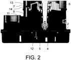
- the cooling jacket outlet 11 opens inside the pump housing 2 but outside the pump chamber 4, namely in an intake area of the impeller 4 on the inflow side and thus in a negative pressure area in front of the pump chamber 4 13 is a longitudinal sectional view of a lower part of the centrifugal pump according to FIG 1 showing 2 is evident.
- the recirculation of the fluid out of the pump chamber 4 minimizes the entry of solids into the peripheral side chamber 9 and improves the operational reliability of the centrifugal pump.
- a pipe 13 also made of stainless steel, is provided in the cooling jacket space 6 , which opens into the cooling jacket outlet 9 at a first end of the cooling jacket space 6 or continues from the cooling jacket outlet 9 into the cooling jacket space 6 .
- the pipe 13 extends in the cooling jacket space 6 parallel to an axis of the impeller 4 in the plane of the drawing vertically upwards to a second end of the cooling jacket space 6 opposite the first end and opens at the second end into the cooling jacket space 6.
- the pipe 13 also bends through 60 degrees at the second end with a radius of 28 mm.
- the tube 13 has a first vent opening 14 with a diameter of 6 mm for discharging solids of greater density and/or weight.
- FIG. 3 shows a schematic, partially transparent centrifugal pump as part of a lifting system on the left and a sectional view of the centrifugal pump as a lifting system according to a further preferred embodiment of the invention on the right.
- the tube 13 is bent through 180 degrees at the second end and extends axially parallel back to the first end.
- the pipe 13 opens into the cooling jacket space 6 and again bends over 60 degrees with a radius of 28 mm.
- a second vent opening 14 is provided in the curved area for discharging solids of low density and/or weight.
- a second pipe 16 is provided in the cooling jacket space, which at the first end of the cooling jacket space 6 opens into the cooling jacket outlet 11 on the one hand and into the cooling jacket space 6 on the other.
- the second tube 16 extends parallel to the tube 13 but is shorter.
- a respective cooling jacket outlet 11 is provided for the tube 13 and the second tube 16 .
- Sufficient fluid is conveyed back into the pump housing 2 through the shorter second pipe 16 so that the risk of the fluid flow in the pump chamber 4 abruptly breaking off is averted.
- the stainless steel tube, the tube 13 and the second tube 16 each have a diameter of 8 mm.
- the described recirculation of the fluid out of the pump chamber 4 reduces the entry of solids into the edge side chamber 6, which improves the operational reliability of the centrifugal pump, since blocking of the impeller 5 by solids otherwise conveyed towards the impeller 5 is reduced.
- sedimentation of the cooling jacket space 6 over time is reduced or even completely avoided, since solids conveyed through the cooling jacket space 6 can be conveyed through the cooling jacket outlet 11 in particular into a suction mouth of the centrifugal pump.
Landscapes
- Engineering & Computer Science (AREA)
- Mechanical Engineering (AREA)
- General Engineering & Computer Science (AREA)
- Physics & Mathematics (AREA)
- Thermal Sciences (AREA)
- Structures Of Non-Positive Displacement Pumps (AREA)
Abstract
Description
- Die Erfindung betrifft eine Kreiselpumpe mit einem Motorgehäuse mit einem in dem Motorgehäuse angeordneten Antriebsmotor und einem an dem Motorgehäuse angeordneten einen Pumpenraum ausbildenden Pumpengehäuse mit einem in dem Pumpenraum angeordneten und von dem Antriebsmotor antreibbaren Laufrad zum Fördern eines Fluids, wobei das Motorgehäuse koaxial außen von einem einen Kühlmantelraum ausbildenden Kühlmantel umgeben ist, welcher Kühlmantelraum einen aus dem Pumpenraum in den Kühlmantelraum mündenden Kühlmanteleinlass aufweist, durch welchen von dem Laufrad gefördertes Fluid in den Kühlmantelraum einströmbar ist. Die Erfindung betrifft ferner eine Verwendung der Kreiselpumpe als Schmutzwasser und/oder Abwasser-Tauchpumpe oder in einer Hebeanlage.
- Wasserdichtgekapselte Tauchmotoren finden insbesondere in Schmutzwasser und/oder Abwasser-Tauchpumpen oder in Hebeanlagen Verwendung. Gegenüber Normmotoren besitzen solche wasserdichtgekapselten Tauchmotoren keine einfache aktive Kühlung mittels eines Luftstroms. Üblicherweise wird die Verlustleistung des Tauchmotors durch passive Kühlung über das ihn umgebende Medium abgeführt. Eine Aufstellung des Tauchmotors in Luft bedingt insofern geringe Betriebszeiten oder Leistungsausbeuten bzw. einen relativ hohen Einsatz aktiver Materialien wie Kupfer oder Eisen. Um unter diesen Aspekten wirtschaftliche Lösungen zu generieren, kommen ölgefüllte Motoren, ölgefüllte Motoren mit interner Kühlung oder trockene Motoren mit externer, geschlossener Umlaufkühlung oder offener Mantelstromkühlung zum Einsatz.
- Bei der Mantelstromkühlung wird der Gesamtvolumenstrom bzw. nur ein Teilvolumenstrom zum Kühlen des Motors in den Kühlmantel eingeleitet, was jedoch zu Problemen und insbesondere zur Reduzierung der Betriebssicherheit führen kann. Denn durch den Kühlmantelraum geförderte Feststoffe können über die Zeit zur Sedimentation des Kühlmantelraums insbesondere bei Abwasserpumpen führen.
- Ausgehend von dieser Situation ist es eine Aufgabe der vorliegenden Erfindung, eine Kreiselpumpe anzugeben, die durch eine verbesserte Betriebssicherheit gekennzeichnet ist.
- Die Aufgabe der Erfindung wird durch die Merkmale des unabhängigen Anspruchs gelöst. Vorteilhafte Ausgestaltungen sind in den Unteransprüchen angegeben.
- Demnach wird die Aufgabe gelöst durch eine Kreiselpumpe mit einem Motorgehäuse mit einem in dem Motorgehäuse angeordneten Antriebsmotor und einem an dem Motorgehäuse angeordneten einen Pumpenraum ausbildenden Pumpengehäuse mit einem in dem Pumpenraum angeordneten und von dem Antriebsmotor antreibbaren Laufrad zum Fördern eines Fluids, wobei
das Motorgehäuse koaxial außen von einem einen Kühlmantelraum ausbildenden Kühlmantel umgeben ist, welcher Kühlmantelraum einen aus dem Pumpenraum in den Kühlmantelraum mündenden Kühlmanteleinlass aufweist, durch welchen von dem Laufrad gefördertes Fluid in den Kühlmantelraum einströmbar ist, und
der Kühlmantelraum einen innerhalb des Pumpengehäuses und außerhalb des Pumpenraums mündenden Kühlmantelauslass aufweist, durch welchen das Fluid aus dem Kühlmantelraum ausströmbar ist. - Ein wesentlicher Punkt der Erfindung ist demnach, dass das Fluid nach Durchströmen des Kühlmantelraums nach Kühlen des Antriebsmotors nicht in den Pumpenraum, beispielsweise nicht in einem Raum hinter dem Laufrad und/oder einem Randseitenraum des Laufrads wie aus dem Stand der Technik bekannt, sondern außerhalb des Pumpenraums ausströmt. Eine Kühlmantelrückströmung erfolgt also zurück vor einen Saugmund der Kreiselpumpe beispielsweise in einen Saugkorb der Kreiselpumpe vor dem Pumpenraum.
- Durch die vorgeschlagene Rückführung des Fluids als Kühlvolumenstrom aus dem Pumpenraum hinaus wird ein Eintrag von Feststoffen in den Randseitenraum wirksam minimiert und somit die Betriebssicherheit der Kreiselpumpe deutlich gesteigert, da derart ein Blockieren des Laufrades reduziert wird. Gleichsam wird eine Sedimentation des Kühlmantelraums über die Zeit verringert oder sogar vollständig vermieden, da durch den Kühlmantelraum geförderte Feststoffe durch den Kühlmantelauslass insbesondere in den Saugmund der Kreiselpumpe förderbar sind.
- Gerade bei Abwasserpumpen ist ein sicherer Betrieb mit einer Kühlmantelraumkühlung nur gewährleistet, wenn in den Pumpenraum immer ein Luftwassergemisch zurückgeführt wird. Sofern die Rückführung des Fluids als Kühlmediums konstruktiv so ausgeführt wird, dass nach einem Einschalten des Antriebsmotors zuerst nur Luft in den Pumpenraum gedrückt wird, kann es zum Abreißen eines Fluidförderstroms kommen. Das Abreißen geschieht insbesondere dann, wenn die im Kühlmantel befindliche Luft durch das zuströmende Fluid komprimiert wird und in der Folge schlagartig in den Pumpenraum entweicht. Bei der vorgeschlagenen Lösung wird dieses Problem dadurch eliminiert, dass das Fluid aus dem Kühlmantel nicht in den Pumpenraum sondern außerhalb diesen entweicht. Mit anderen Worten ist ein Rücklauf des Fluids so gestaltet, dass das Laufrad stets mit genügendem Fluid beaufschlagt ist und ein plötzlicher Eintrag von Luft vermieden wird.
- Als Kreiselpumpe wird im Allgemeinen eine Strömungsmaschine bezeichnet, die eine Drehbewegung und dynamische Kräfte zur Förderung überwiegend von Flüssigkeiten als Fluid nutzt. Neben einer tangentialen Beschleunigung des Fluids, auch Medium genannt, wird in radialer Strömung auftretende Fliehkraft zur Förderung genutzt, so dass Kreiselpumpen ebenso als Zentrifugalpumpen bezeichnet werden. Im regulären Betrieb der Kreiselpumpe ist das Motorgehäuse bevorzugt oberhalb des Pumpengehäuses angeordnet, mit diesem ortsfest verbunden und/oder einteilig gestaltet. Das Fluid umfasst bevorzugt Wasser oder ein sonstiges flüssiges Medium wie beispielsweise Abwasser. Das Fluid kann Feststoffe wie beispielsweise Verunreinigungen jeglicher Art, insbesondere Fäkalien, Sedimente, Dreck, Sand, oder auch kleinere Holz-, Gestrüpp-, Textilien- oder Lappenteile oder dergleichen umfassen. Das Laufrad ist bevorzugt vollständig in dem Pumpenraum angeordnet.
- Das Motorgehäuse und/oder der Kühlmantel kann eine zylinderartige Form umfassen, welche konisch weg vom Pumpengehäuse zulaufen kann. Bevorzugt ist das Motorgehäuse und/oder der Kühlmantelraum aus Metall, insbesondere aus Edelstahl, und/oder das Pumpengehäuse aus Kunststoff gestaltet. Bevorzugt umgibt der Kühlmantelraum das Motorgehäuse wenigstens zum Teil und insbesondere vollständig, besonders bevorzugt entlang einer Mantelfläche des Motorgehäuses. Der Kühlmanteleinlass ist bevorzugt in einem Druckabgang des Pumpengehäuses und/oder derart in dem Pumpengehäuse angeordnet, dass eine Rotationsbewegung des Laufrads Fluid in den Kühlmantelraum einströmen lässt und/oder pumpt. Der Kühlmantelraum ist bevorzugt bis auf den Kühlmanteleinlass und den Kühlmantelauslass fluiddicht geschlossen.
- Nach einer bevorzugten Weiterbildung mündet der Kühlmantelauslass in einem Ansaugbereich des Laufrades vor dem Pumpenraum und/oder mündet der Kühlmantelauslass anströmseitig vor dem Pumpenraum. Eine Rückführung des Fluids erfolgt also nicht hinter das Laufrad wie bei den aus dem Stand der Technik bekannten Ausgestaltungen, sondern in jedem Fall außerhalb des das Laufrad aufweisenden Pumpenraums, insbesondere wie durch die Weiterbildung vorgeschlagen vor den Pumpenraum, was eine Gefahr des Abreißens des Fluidförderstroms eliminiert oder zumindest merklich reduziert.
- Gemäß einer anderen bevorzugten Weiterbildung ist der Kühlmanteleinlass in einem Überdruckbereich des Pumpenraums angeordnet und/oder ist der Kühlmantelauslass in einem Unterdruckbereich des Pumpengehäuses angeordnet. Der Überdruckbereich ist bevorzugt hinter dem Laufrad in dem sogenannten Randseitenraum des Pumpenraums vorgesehen. Der Unterdruckbereich ist bevorzugt in einem Ansaugbereich des Pumpengehäuses vor dem Pumpenraum vorgesehen. Durch einen Differenzdruck zwischen Kühlmanteleinlass, an dem aufgrund der Rotationsbewegung des Laufrads Überdruck entsteht, und Kühlmantelauslass, mit demgegenüber geringerem Unterdruck, strömt Fluid durch den Kühlmantel vom Kühlmanteleinlass zum Kühlmantelauslass zum Kühlen des Antriebsmotors.
- Nach einer weiteren bevorzugten Ausgestaltung weist das Pumpengehäuse einen anströmseitig vor dem Pumpenraum vorgesehenen Saugkorb auf, wobei der Kühlmantelauslass von dem Saugkorb verdeckt ist. Der Saugkorb kann als eine gitterartige Ausgestaltung gestaltet sein und unterhalb einer Bodenplatte des Pumpengehäuses vorgesehen sein, Teil der Bodenplatte und/oder des Pumpengehäuses sein und/oder einstückig mit diesen gestaltet sein. Derart befindet sich der Saugkorb in dem Ansaugbereich und/oder Unterdruckbereich der Kreiselpumpe.
- Gemäß einer anderen bevorzugten Weiterbildung weist die Kreiselpumpe ein in dem Kühlmantelraum vorgesehenes Rohr auf, welches einerseits an einem ersten Ende des Kühlmantelraums in den Kühlmantelauslass mündet, sich achsparallel zu einer Achse des Laufrades bis hin zu einem zu dem ersten Ende entgegengesetzten zweiten Ende des Kühlmantelraums erstreckt und andererseits an dem zweiten Ende in den Kühlmantelraum mündet. Bevorzugt ist das Rohr an dem zweiten Ende zum Ausbilden einer zirkularen Strömung gebogen, beispielsweise mit einem Radius von 28 mm über 15, 30 oder 45 Grad oder mehr Grad. Das Rohr ist bevorzugt aus Metall, insbesondere aus Edelstahl ausgeführt. Bevorzugt bildet das erste Ende den Kühlmantelauslass aus. Das Rohr weist bevorzugt einen Durchmesser von 8, 10 oder 12 mm auf. Im regulären Betrieb ist das erste Ende bevorzugt an einem unteren Rand des Kühlmantels dem Motorgehäuse zugewandt und das zweite Ende bevorzugt an einem oberen Rand des Kühlmantels dem Motorgehäuse abgewandt. Kühlmantelauslass und Rohr können einstückig ausgebildet sein. Ebenso kann der Kühlmantelauslass in das Pumpengehäuse eingefügt sein, beispielsweise durch Fräsen, in welches das Rohr einsteckbar ist.
- Ferner kann ein in dem Kühlmantelraum vorgesehenes Kühlmanteleinlassrohr vorgesehen sein, welches einerseits an einem ersten Ende des Kühlmantelraums in den Kühlmanteleinlass mündet, sich achsparallel zu einer Achse des Laufrades bis hin zu einem zu dem ersten Ende entgegengesetzten zweiten Ende des Kühlmantelraums erstreckt und andererseits an dem zweiten Ende in den Kühlmantelraum mündet. Kühlmanteleinlass und Kühlmanteleinlassrohr können einstückig ausgebildet sein. Ebenso kann der Kühlmanteleinlass in das Pumpengehäuse eingefügt sein, beispielsweise durch Fräsen, in welches das Kühlmanteleinlassrohr einsteckbar ist.
- Nach einer weiteren bevorzugten Ausgestaltung weist das Rohr an dem ersten Ende in dem Kühlmantelraum eine erste Entlüftungsöffnung auf. Durch die erste Entlüftungsöffnung können Feststoffe größerer Dichte und/oder Gewicht abgeführt werden. Ferner wird durch die erste Entlüftungsöffnung die Betriebssicherheit der Kreiselpumpe verbessert, da aufgrund der ersten Entlüftungsöffnung Luft nicht schlagartig in das Pumpengehäuse entweichen kann. Die erste Entlüftungsöffnung weist bevorzugt einen Durchmesser von 3, 4, 5, 6, 7 oder 8 mm auf. Weiter bevorzugt weist das Rohr an dem ersten Ende zwei gegenüberliegend vorgesehene erste Entlüftungsöffnungen auf. Die erste Entlüftungsöffnung kann als Querbohrung gestaltet sein.
- Gemäß einer anderen bevorzugten Weiterbildung ist das Rohr an dem zweiten Ende gebogen, erstreckt sich achsparallel bis hin zu dem ersten Ende zurück und mündet anderseits an dem ersten Ende in den Kühlmantelraum. Das Rohr ist an dem zweiten Ende bevorzugt um 180 Grad oder annähernd um 180 Grad gebogen. An dem ersten Ende ist das Rohr zum Ausbilden einer zirkularen Strömung bevorzugt gebogen, beispielsweise mit einem Radius von 28 mm über 15, 30, 45 oder 60 Grad. Das Rohr kann sich ebenso annähernd achsparallel, beispielsweise um einige Grad verschwenkt, bis hin zu dem ersten Ende zurückerstrecken.
- Nach einer weiteren bevorzugten Ausgestaltung ist in dem gebogenen Bereich eine zweite Entlüftungsöffnung vorgesehen. Durch die zweite Entlüftungsöffnung können Feststoffe geringerer Dichte und/oder Gewicht abgeführt werden. Ferner kann durch die zweite Entlüftungsöffnung der Kühlmantel prozesssicher entlüftet werden und es kann verhindert werden, dass der Kühlmantel bei in dem Kühlmantel absinkendem Fluidniveau nicht über den Kühlmantelauslass leer gesaugt wird. Die zweite Entlüftungsöffnung weist bevorzugt einen Durchmesser von 3, 4, 5, 6, 7 oder 8 mm auf. Die zweite Entlüftungsöffnung kann als Querbohrung gestaltet sein. Weiter bevorzugt weist das Rohr zwei gegenüberliegend vorgesehene zweite Entlüftungsöffnungen auf.
- Gemäß einer anderen bevorzugten Weiterbildung weist die Kreiselpumpe ein zweites in dem Kühlmantelraum vorgesehenes Rohr auf, welches an dem ersten Ende des Kühlmantelraums einerseits in den Kühlmantelauslass und andererseits in den Kühlmantelraum mündet. Bevorzugt ist das zweite Rohr einstückig mit dem Kühlmantelauslass gestaltet. Zu diesem Zweck können zwei Kühlmantelauslässe vorgesehen sein, welche nebeneinander benachbart angeordnet sein können. Ebenso kann das zweite Rohr in den Kühlmantelausass einsteckbar gestaltet sein. Durch das zweite Rohr können Partikel größerer Dichte im unteren Bereich des Kühlmantels abgeführt werden. Ferner wird durch das zweite Rohr die Betriebssicherheit der Kreiselpumpe verbessert, da aufgrund des zweiten Rohrs Luft nicht schlagartig in das Pumpengehäuse entweichen kann. Das zweite Rohr ist bevorzugt kürzer als das erste Rohr gestaltet. Das zweite Rohr weist bevorzugt einen Durchmesser von 8, 10 oder 12 mm auf.
- Nach einer bevorzugten Weiterbildung ist die Kreiselpumpe als Tauchpumpe oder als Hebeanlage ausgeführt. Als Tauchpumpewird eine transportable oder stationär eingebaute Kreiselpumpe verstanden, die in die zu fördernde Flüssigkeit als Fluid eingetaucht wird. Tauchpumpen finden insbesondere in der Wasserversorgung und in der Abwasserentsorgung Verwendung. Tauchpumpen dienen unter Anderem zum Fördern grob verunreinigten Fluids, wie insbesondere Abwasser oder Schmutzwasser aber auch für andere fluide Medien, mit einem hohem Feststoffanteil wie beispielsweise Steinen, Geröll und Ähnlichem. Als Laufradformen finden insbesondere Freistromrad, Einkanalrad, Mehrkanalrad, Diagonalrad, Schraubenrad und Propellerrad Verwendung. Als Hebeanlagen werden automatisch arbeitende Anlagen verstanden, die Abwasser, das unter einer Rückstauebene anfällt, rückstausicher ableiten oder auf ein höherliegendes Niveau pumpen. Die Abwasserhebeanlage wird in der Regel an einem tiefsten Punkt in einem Keller entweder frei oder in einer Grube aufgebaut, oder in einem Schacht, einem sogenannten Pumpensumpf, untergebracht.
- Die Aufgabe der Erfindung wird weiterhin gelöst durch eine Verwendung einer Kreiselpumpe wie zuvor beschrieben als Schmutzwasser und/oder Abwasser-Tauchpumpe oder in einer Hebeanlage. Darüber hinaus lässt sich die Kreiselpumpe auch für eine Trinkwasseranlage oder sonstige Fluid-fördernde Anwendungen verwenden, wobei hier nicht genannte Anlagenarten umfasst sein können. Schmutzwasser- und/oder Abwasser-Tauchpumpen dienen insbesondere zum Abpumpen von verdrecktem Wasser beispielsweise von Hochwasser, in überfluteten Baugruben, in Waschküchen, in schlammigen Gruben, in Biotopen und/oder von Gartenteichen, von Sickerschächten sowie in Kellern, uns insbesondere zum Pumpen von Fluiden wie Wasser mit verschiedenen Verunreinigungsgraden wie beispielsweise Steine, Schlamm oder Geröll.
- Insbesondere der Eintrag von Steinchen als Feststoffe in den Randseitenraum kann bei aus dem Stand der Technik bekannten Schmutzwasserpumpen zu häufigem Blockieren des Laufrads führen und die Betriebssicherheit deutlich herabsetzen. Durch die vorgeschlagene Verwendung lässt sich langfristig ein hoher Wirkungsgrad der Schmutzwasser- und/oder Abwasser-Tauchpumpe sicherstellen, da das vorgenannte Problem wie ebenso bei einer Hebeanlage eliminiert wird. Bei einer Hebeanlage lässt sich bei der vorgeschlagenen Lösung auf aus dem Stand der Technik bekannten Entlüftungsleitungen außerhalb des Kühlmantels verzichten und die Entlüftung des Kühlmantels durch die vorgeschlagene Lösung bewerkstelligen.
- Nachfolgend wird die Erfindung unter Bezugnahme auf die anliegenden Zeichnungen anhand bevorzugter Ausführungsbeispiele näher erläutert.
- In den Zeichnungen zeigen
- Fig. 1
- eine schematische teilgeöffnete Seitansicht einer Kreiselpumpe als Schmutzwasserpumpe gemäß einem bevorzugten Ausführungsbeispiel der Erfindung,
- Fig. 2
- eine Schnittansicht eines unteren Teils der Kreiselpumpe gemäß
Fig. 1 , - Fig. 3
- links eine schematische teildursichtige Kreiselpumpe als Teil einer Hebeanlage sowie rechts eine Schnittansicht der Kreiselpumpe als Teil einer Hebeanlage gemäß einem weiteren bevorzugten Ausführungsbeispiel der Erfindung, und
- Fig. 4
- eine Schnittansicht eines unteren Teils einer Kreiselpumpe als Abwasserpumpe gemäß einem weiteren bevorzugten Ausführungsbeispiel der Erfindung.
-
Fig. 1 zeigt eine schematische teilgeöffnete Seitansicht in Querrichtung einer Kreiselpumpe als Schmutzwasserpumpe gemäß einem bevorzugten Ausführungsbeispiel der Erfindung. - Die Kreiselpumpe weist ein Motorgehäuse 1 aus Edelstahl auf, welches auf einem Pumpengehäuse 2 aus Kunststoff aufgesetzt ist. In dem Motorgehäuse 1 ist ein Antriebsmotor 3, in
Fig. 3 gezeigt, vorgesehen, welcher über eine inFig. 3 gezeigte senkrecht stehende Welle ein in einem vom dem Pumpengehäuse 2 ausgebildeten Pumpenraum 4 vorgesehenes Laufrad 5 zum Fördern von Wasser als Fluid antreibt. Das zylinderartige Motorgehäuse 1 ist koaxial außen an seiner Mantelfläche umlaufend von einem einen Kühlmantelraum 6 ausbildenden zylinderartigen Kühlmantel 7 umgeben. Der Kühlmantel 7 ist in der Zeichnungsebene mittig geöffnet dargestellt, um einen teilweisen Einblick in den Kühlmantelraum 6 zu gewähren. - In dem Kühlmantelraum 6 ist einerseits ein rohrartiger Kühlmanteleinlass 8 vorgesehen, der aus dem Pumpenraum 4 in den Kühlmantelraum 6 mündet. Der Kühlmanteleinlass 8 mündet in dem Pumpenraum 4 in einem Überdruckbereich des Pumpenraums 4 in einen sogenannten Randseitenraum 9, so dass das Laufrad beim Rotieren Fluid durch den Kühlmanteleinlass 8 in den Kühlmantelraum 6 hineinfördert. Der rohrartige Kühlmanteleinlass 8 setzt sich über ein Edelstahlrohr 10 von dem Pumpenraums 4 zunächst in der Zeichnungsebene vertikal nach oben in den Pumpenraum 4 fort und knickt in dem Kühlmantelraum 6 zum Ausbilden einer zirkularen Strömung zu seinem Ende hin mit einem Radius von 28 mm über 60° gebogen ab.
- Zum Rückführen des derart in den Kühlmantelraum 6 geförderten Fluids ist andererseits ein Kühlmantelauslass 11 vorgesehen, der sich in dem Kühlmantelraum 6 parallel zu dem Edelstahlrohr 10 bzw. dem rohrartigen Kühlmanteleinlass 8 erstreckt. Der Kühlmantelauslass 11 mündet innerhalb des Pumpengehäuses 2 jedoch außerhalb des Pumpenraums 4, nämlich in einem Ansaugbereich des Laufrades 4 anströmseitig und derart in einem Unterdruckbereich vor dem Pumpenraum 4. Ein anströmseitig vor dem Pumpenraum 4 vorgesehener Saugkorb 12 verdeckt den Kühlmantelauslass 11, wie auch aus der eine Schnittansicht in Längsrichtung eines unteren Teils der Kreiselpumpe gemäß
Fig. 1 zeigendenFig. 2 ersichtlich ist. Durch die Rückführung des Fluids aus dem Pumpenraum 4 hinaus wird ein Eintrag von Feststoffen in den Randseitenraum 9 minimiert und die Betriebssicherheit der Kreiselpumpe verbessert. - Wie insbesondere auf
Fig. 1 ersichtlich, ist in dem Kühlmantelraum 6 ein ebenso aus Edelstahl bestehendes Rohr 13 vorgesehen, welches an einem ersten Ende des Kühlmantelraums 6 in den Kühlmantelauslass 9 mündet bzw. sich von diesem von dem Kühlmantelauslass 9 in den Kühlmantelraum 6 fortsetzt. Das Rohr 13 erstreckt sich in dem Kühlmantelraum 6 achsparallel zu einer Achse des Laufrades 4 in der Zeichnungsebene senkrecht nach oben bis hin zu einem zu dem ersten Ende entgegengesetzten zweiten Ende des Kühlmantelraums 6 und mündet an dem zweiten Ende in den Kühlmantelraum 6. Das Rohr 13 knickt an dem zweiten Ende ebenso mit einem Radius von 28 mm über 60 Grad gebogen ab. An dem ersten Ende weist das Rohr 13 eine erste Entlüftungsöffnung 14 mit einem Durchmesser von 6 mm zum Abführen von Feststoffen größerer Dichte und/oder Gewicht auf. -
Fig. 3 zeigt links eine schematische teildurchsichtige Kreiselpumpe als Teil einer Hebeanlage sowie rechts eine Schnittansicht der Kreiselpumpe als Hebeanlage gemäß einem weiteren bevorzugten Ausführungsbeispiel der Erfindung. Wie in der Figur links zu erkennen, ist das Rohr 13 an dem zweiten Ende um 180 Grad gebogen und erstreckt sich achsparallel zurück bis hin zu dem ersten Ende. An dem ersten Ende mündet das Rohr 13 in den Kühlmantelraum 6 und knickt wiederum mit einem Radius von 28 mm über 60 Grad gebogen ab. In dem gebogenen Bereich ist eine zweite Entlüftungsöffnung 14 zum Abführen von Feststoffen geringer Dichte und/oder Gewicht vorgesehen. - Schließlich zeigt
Fig. 4 eine Schnittansicht eines unteren Teils einer Kreiselpumpe als Abwasserpumpe gemäß einem weiteren bevorzugten Ausführungsbeispiel der Erfindung. Neben dem Rohr 13 ist ein zweite Rohr 16 in dem Kühlmantelraum vorgesehen, welches an dem ersten Ende des Kühlmantelraums 6 einerseits in den Kühlmantelauslass 11 und andererseits in den Kühlmantelraum 6 mündet. Das zweite Rohr 16 erstreckt sich parallel zu dem Rohr 13, ist jedoch kürzer. Für das Rohr 13 und das zweite Rohr 16 ist ein jeweiliger Kühlmantelauslass 11 vorgesehen. Durch das kürzere zweite Rohr 16 wird ausreichend Fluid zurück in das Pumpengehäuse 2 gefördert, so dass die Gefahr eines schlagartigen Abreißens des Fluidstroms im Pumpenraum 4 gebannt ist. Das Edelstahlrohr, das Rohr 13 sowie das zweite Rohr 16 weisen jeweils einen Durchmesser von 8 mm auf. - Durch die beschriebene Rückführung des Fluids aus dem Pumpenraum 4 hinaus wird ein Eintrag von Feststoffen in den Randseitenraum 6 reduziert, wodurch sich die Betriebssicherheit der Kreiselpumpe verbessert, da derart ein Blockieren des Laufrades 5 durch ansonsten hin zum Laufrad 5 hin geförderte Feststoffe reduziert wird. Gleichsam wird eine Sedimentation des Kühlmantelraums 6 über die Zeit verringert oder sogar vollständig vermieden, da durch den Kühlmantelraum 6 geförderte Feststoffe durch den Kühlmantelauslass 11 insbesondere in einen Saugmund der Kreiselpumpe förderbar sind.
- Die beschriebenen Ausführungsbeispiele sind lediglich Beispiele, die im Rahmen der Ansprüche auf vielfältige Weise modifiziert und/oder ergänzt werden können. Jedes Merkmal, das für ein bestimmtes Ausführungsbeispiel beschrieben wurde, kann eigenständig oder in Kombination mit anderen Merkmalen in einem beliebigen anderen Ausführungsbeispiel genutzt werden. Jedes Merkmal, dass für ein Ausführungsbeispiel einer bestimmten Kategorie beschrieben wurde, kann auch in entsprechender Weise in einem Ausführungsbeispiel einer anderen Kategorie eingesetzt werden.
Bezugszeichenliste Motorgehäuse 1 Pumpengehäuse 2 Antriebsmotor 3 Pumpenraum 4 Laufrad 5 Kühlmantelraum 6 Kühlmantel 7 Kühlmanteleinlass 8 Randseitenraum 9 Edelstahlrohr 10 Kühlmantelauslass 11 Saugkorb 12 Rohr 13 Erste Entlüftungsöffnung 14 Zweite Entlüftungsöffnung 15 Zweiten Rohr 16
Claims (11)
- Kreiselpumpe mit einem Motorgehäuse (1) mit einem in dem Motorgehäuse (1) angeordneten Antriebsmotor (3) und einem an dem Motorgehäuse (1) angeordneten einen Pumpenraum (4) ausbildenden Pumpengehäuse (2) mit einem in dem Pumpenraum (4) angeordneten und von dem Antriebsmotor (3) antreibbaren Laufrad (5) zum Fördern eines Fluids, wobei
das Motorgehäuse (1) koaxial außen von einem einen Kühlmantelraum (6) ausbildenden Kühlmantel (7) umgeben ist,
der Kühlmantelraum (6) einen aus dem Pumpenraum (4) in den Kühlmantelraum (6) mündenden Kühlmanteleinlass (8) aufweist, durch welchen von dem Laufrad (5) gefördertes Fluid in den Kühlmantelraum (6) einströmbar ist, und
der Kühlmantelraum (6) einen innerhalb des Pumpengehäuses (2) und außerhalb des Pumpenraums (4) mündenden Kühlmantelauslass (11) aufweist, durch welchen das Fluid aus dem Kühlmantelraum (6) ausströmbar ist. - Kreiselpumpe nach dem vorhergehenden Anspruch, wobei der Kühlmantelauslass (11) in einem Ansaugbereich des Laufrads (5) vor dem Pumpenraum (4) mündet und/oder der Kühlmantelauslass (11) anströmseitig vor dem Pumpenraum (4) mündet.
- Kreiselpumpe nach einem der vorhergehenden Ansprüche, wobei der Kühlmanteleinlass (8) in einem Überdruckbereich des Pumpenraums (4) angeordnet ist und/oder der Kühlmantelauslass (11) in einem Unterdruckbereich des Pumpengehäuses (3) angeordnet ist.
- Kreiselpumpe nach einem der vorhergehenden Ansprüche, wobei das Pumpengehäuse (2) einen anströmseitig vor dem Pumpenraum (4) vorgesehenen Saugkorb (12) aufweist und der Kühlmantelauslass (11) von dem Saugkorb (12) verdeckt ist.
- Kreiselpumpe nach einem der vorhergehenden Ansprüche, mit einem in dem Kühlmantelraum (6) vorgesehenen Rohr (13), welches einerseits an einem ersten Ende des Kühlmantelraums (6) in den Kühlmantelauslass (11) mündet, sich achsparallel zu einer Achse des Laufrads (5) bis hin zu einem zu dem ersten Ende entgegengesetzten zweiten Ende des Kühlmantelraums (6) erstreckt und andererseits an dem zweiten Ende in den Kühlmantelraum (6) mündet.
- Kreiselpumpe nach dem vorhergehenden Anspruch, wobei das Rohr (13) an dem ersten Ende des Kühlmantelraums (6) eine erste Entlüftungsöffnung (14) aufweist.
- Kreiselpumpe nach einem der beiden vorhergehenden Ansprüche, wobei das Rohr (13) an dem zweiten Ende gebogen ist, sich achsparallel bis hin zu dem ersten Ende zurück erstreckt und an dem ersten Ende in den Kühlmantelraum (6) mündet.
- Kreiselpumpe nach dem vorhergehenden Anspruch, wobei in dem gebogenen Bereich eine zweite Entlüftungsöffnung (15) vorgesehen ist.
- Kreiselpumpe nach einem der vier vorhergehenden Ansprüche, mit einem zweiten in dem Kühlmantelraum (6) vorgesehen Rohr (16), welches an dem ersten Ende des Kühlmantelraums (6) einerseits in den Kühlmantelauslass (11) und andererseits in den Kühlmantelraum (6) mündet.
- Kreiselpumpe nach einem der vorhergehenden Ansprüche, wobei die Kreiselpumpe als Tauchpumpe oder als Hebeanlage ausgeführt ist.
- Verwendung einer Kreiselpumpe nach einem der vorhergehenden Kreiselpumpen-Ansprüche als Schmutzwasser und/oder Abwasser-Tauchpumpe oder in einer Hebeanlage.
Applications Claiming Priority (1)
| Application Number | Priority Date | Filing Date | Title |
|---|---|---|---|
| LU101956A LU101956B1 (de) | 2020-07-27 | 2020-07-27 | Kreiselpumpe |
Publications (2)
| Publication Number | Publication Date |
|---|---|
| EP3945218A1 true EP3945218A1 (de) | 2022-02-02 |
| EP3945218B1 EP3945218B1 (de) | 2024-05-22 |
Family
ID=72474355
Family Applications (1)
| Application Number | Title | Priority Date | Filing Date |
|---|---|---|---|
| EP21187851.7A Active EP3945218B1 (de) | 2020-07-27 | 2021-07-27 | Kreiselpumpe |
Country Status (3)
| Country | Link |
|---|---|
| EP (1) | EP3945218B1 (de) |
| LU (1) | LU101956B1 (de) |
| PL (1) | PL3945218T3 (de) |
Citations (7)
| Publication number | Priority date | Publication date | Assignee | Title |
|---|---|---|---|---|
| JPS51154703U (de) * | 1975-05-31 | 1976-12-09 | ||
| EP0531267A2 (de) * | 1991-09-03 | 1993-03-10 | ITT Flygt Aktiebolag | Motorkühlungsvorrichtung |
| DE4319619A1 (de) * | 1993-06-14 | 1994-12-15 | Wilo Gmbh | Tauchmotorpumpe |
| JP2001304197A (ja) * | 2000-04-28 | 2001-10-31 | Kubota Corp | 水中ポンプ |
| DE102005034341A1 (de) * | 2005-07-22 | 2007-01-25 | Ksb Aktiengesellschaft | Tauchmotorpumpe mit Kühlmantel |
| DE102007036240A1 (de) * | 2007-08-02 | 2009-02-05 | Continental Automotive Gmbh | Flüssigkeitspumpe |
| CN105673574A (zh) * | 2016-03-18 | 2016-06-15 | 池泉 | 低噪音多级离心泵 |
-
2020
- 2020-07-27 LU LU101956A patent/LU101956B1/de active IP Right Grant
-
2021
- 2021-07-27 PL PL21187851.7T patent/PL3945218T3/pl unknown
- 2021-07-27 EP EP21187851.7A patent/EP3945218B1/de active Active
Patent Citations (7)
| Publication number | Priority date | Publication date | Assignee | Title |
|---|---|---|---|---|
| JPS51154703U (de) * | 1975-05-31 | 1976-12-09 | ||
| EP0531267A2 (de) * | 1991-09-03 | 1993-03-10 | ITT Flygt Aktiebolag | Motorkühlungsvorrichtung |
| DE4319619A1 (de) * | 1993-06-14 | 1994-12-15 | Wilo Gmbh | Tauchmotorpumpe |
| JP2001304197A (ja) * | 2000-04-28 | 2001-10-31 | Kubota Corp | 水中ポンプ |
| DE102005034341A1 (de) * | 2005-07-22 | 2007-01-25 | Ksb Aktiengesellschaft | Tauchmotorpumpe mit Kühlmantel |
| DE102007036240A1 (de) * | 2007-08-02 | 2009-02-05 | Continental Automotive Gmbh | Flüssigkeitspumpe |
| CN105673574A (zh) * | 2016-03-18 | 2016-06-15 | 池泉 | 低噪音多级离心泵 |
Also Published As
| Publication number | Publication date |
|---|---|
| EP3945218B1 (de) | 2024-05-22 |
| PL3945218T3 (pl) | 2024-08-05 |
| LU101956B1 (de) | 2022-01-27 |
Similar Documents
| Publication | Publication Date | Title |
|---|---|---|
| DE69206082T2 (de) | Motorkühlungsvorrichtung. | |
| DE69005510T2 (de) | Pumpe um Gas von einer zu pumpenden Flüssigkeit abzutrennen. | |
| WO2014187648A1 (de) | Mehrstufiges selbstansaugendes kreiselpumpenaggregat | |
| DE69119183T3 (de) | Kreiselpumpe mit Abdichtungsmitteln | |
| WO2011079892A1 (de) | Tauchpumpe | |
| DE7507522U (de) | Kreiselpumpe | |
| LU101566B1 (de) | Kreiselpumpe mit einem selbsttätigen Ventil | |
| EP3945218B1 (de) | Kreiselpumpe | |
| WO2011091809A1 (de) | Gartenpumpenanordnung | |
| DE102005034341A1 (de) | Tauchmotorpumpe mit Kühlmantel | |
| DE29514402U1 (de) | Vorrichtung zum Verbessern des Ansaugverhaltens von Strömungsförderpumpen | |
| DE69607779T2 (de) | Variabler Pegelabsaugvorrichtung | |
| EP3978760B1 (de) | Tauchkreiselpumpe | |
| EP3405677B1 (de) | Entlüftungseinrichtung für eine pumpe in einem behälter | |
| DE3538050A1 (de) | Zentrifugalpumpe | |
| EP0599204A1 (de) | Tauchpumpenaggregat | |
| DE29710133U1 (de) | Vorrichtung zum beruhigenden und verwirbelungsarmen Sammeln und Heben von Abwässern | |
| DE3539883A1 (de) | Selbstansaugende kreiselpumpe | |
| AT246671B (de) | Tauchbarer Zentrifugalgasabscheider | |
| EP1522734B1 (de) | Verfahren zum Betreiben einer Hebeeinrichtung zum Abpumpen von verunreinigten flüssigen Medien, insbesondere Kühlschmiermittel | |
| EP4202223A1 (de) | Kreiselpumpe zum fördern eines fluids | |
| DE2526032A1 (de) | Abwasserhebeanlage fuer einen im erdreich eingebetteten sammelbehaelter | |
| EP3405681B1 (de) | Entlüftungseinrichtung für eine pumpe in einem behälter | |
| DE102024124629A1 (de) | Vorrichtung für eine Kreiselpumpenanordnung | |
| DE69407257T2 (de) | Gehäuse für eine Rotationspumpe |
Legal Events
| Date | Code | Title | Description |
|---|---|---|---|
| PUAI | Public reference made under article 153(3) epc to a published international application that has entered the european phase |
Free format text: ORIGINAL CODE: 0009012 |
|
| STAA | Information on the status of an ep patent application or granted ep patent |
Free format text: STATUS: THE APPLICATION HAS BEEN PUBLISHED |
|
| AK | Designated contracting states |
Kind code of ref document: A1 Designated state(s): AL AT BE BG CH CY CZ DE DK EE ES FI FR GB GR HR HU IE IS IT LI LT LU LV MC MK MT NL NO PL PT RO RS SE SI SK SM TR |
|
| STAA | Information on the status of an ep patent application or granted ep patent |
Free format text: STATUS: REQUEST FOR EXAMINATION WAS MADE |
|
| 17P | Request for examination filed |
Effective date: 20220705 |
|
| RBV | Designated contracting states (corrected) |
Designated state(s): AL AT BE BG CH CY CZ DE DK EE ES FI FR GB GR HR HU IE IS IT LI LT LU LV MC MK MT NL NO PL PT RO RS SE SI SK SM TR |
|
| P01 | Opt-out of the competence of the unified patent court (upc) registered |
Effective date: 20230615 |
|
| GRAP | Despatch of communication of intention to grant a patent |
Free format text: ORIGINAL CODE: EPIDOSNIGR1 |
|
| STAA | Information on the status of an ep patent application or granted ep patent |
Free format text: STATUS: GRANT OF PATENT IS INTENDED |
|
| INTG | Intention to grant announced |
Effective date: 20231213 |
|
| GRAS | Grant fee paid |
Free format text: ORIGINAL CODE: EPIDOSNIGR3 |
|
| GRAA | (expected) grant |
Free format text: ORIGINAL CODE: 0009210 |
|
| STAA | Information on the status of an ep patent application or granted ep patent |
Free format text: STATUS: THE PATENT HAS BEEN GRANTED |
|
| AK | Designated contracting states |
Kind code of ref document: B1 Designated state(s): AL AT BE BG CH CY CZ DE DK EE ES FI FR GB GR HR HU IE IS IT LI LT LU LV MC MK MT NL NO PL PT RO RS SE SI SK SM TR |
|
| REG | Reference to a national code |
Ref country code: GB Ref legal event code: FG4D Free format text: NOT ENGLISH |
|
| REG | Reference to a national code |
Ref country code: CH Ref legal event code: EP |
|
| REG | Reference to a national code |
Ref country code: DE Ref legal event code: R096 Ref document number: 502021003771 Country of ref document: DE |
|
| REG | Reference to a national code |
Ref country code: IE Ref legal event code: FG4D Free format text: LANGUAGE OF EP DOCUMENT: GERMAN |
|
| REG | Reference to a national code |
Ref country code: LT Ref legal event code: MG9D |
|
| REG | Reference to a national code |
Ref country code: NL Ref legal event code: MP Effective date: 20240522 |
|
| PG25 | Lapsed in a contracting state [announced via postgrant information from national office to epo] |
Ref country code: IS Free format text: LAPSE BECAUSE OF FAILURE TO SUBMIT A TRANSLATION OF THE DESCRIPTION OR TO PAY THE FEE WITHIN THE PRESCRIBED TIME-LIMIT Effective date: 20240922 |
|
| PG25 | Lapsed in a contracting state [announced via postgrant information from national office to epo] |
Ref country code: BG Free format text: LAPSE BECAUSE OF FAILURE TO SUBMIT A TRANSLATION OF THE DESCRIPTION OR TO PAY THE FEE WITHIN THE PRESCRIBED TIME-LIMIT Effective date: 20240522 |
|
| PG25 | Lapsed in a contracting state [announced via postgrant information from national office to epo] |
Ref country code: HR Free format text: LAPSE BECAUSE OF FAILURE TO SUBMIT A TRANSLATION OF THE DESCRIPTION OR TO PAY THE FEE WITHIN THE PRESCRIBED TIME-LIMIT Effective date: 20240522 Ref country code: FI Free format text: LAPSE BECAUSE OF FAILURE TO SUBMIT A TRANSLATION OF THE DESCRIPTION OR TO PAY THE FEE WITHIN THE PRESCRIBED TIME-LIMIT Effective date: 20240522 |
|
| PG25 | Lapsed in a contracting state [announced via postgrant information from national office to epo] |
Ref country code: GR Free format text: LAPSE BECAUSE OF FAILURE TO SUBMIT A TRANSLATION OF THE DESCRIPTION OR TO PAY THE FEE WITHIN THE PRESCRIBED TIME-LIMIT Effective date: 20240823 |
|
| PG25 | Lapsed in a contracting state [announced via postgrant information from national office to epo] |
Ref country code: PT Free format text: LAPSE BECAUSE OF FAILURE TO SUBMIT A TRANSLATION OF THE DESCRIPTION OR TO PAY THE FEE WITHIN THE PRESCRIBED TIME-LIMIT Effective date: 20240923 |
|
| PG25 | Lapsed in a contracting state [announced via postgrant information from national office to epo] |
Ref country code: NL Free format text: LAPSE BECAUSE OF FAILURE TO SUBMIT A TRANSLATION OF THE DESCRIPTION OR TO PAY THE FEE WITHIN THE PRESCRIBED TIME-LIMIT Effective date: 20240522 |
|
| PG25 | Lapsed in a contracting state [announced via postgrant information from national office to epo] |
Ref country code: ES Free format text: LAPSE BECAUSE OF FAILURE TO SUBMIT A TRANSLATION OF THE DESCRIPTION OR TO PAY THE FEE WITHIN THE PRESCRIBED TIME-LIMIT Effective date: 20240522 |
|
| PG25 | Lapsed in a contracting state [announced via postgrant information from national office to epo] |
Ref country code: LV Free format text: LAPSE BECAUSE OF FAILURE TO SUBMIT A TRANSLATION OF THE DESCRIPTION OR TO PAY THE FEE WITHIN THE PRESCRIBED TIME-LIMIT Effective date: 20240522 |
|
| PG25 | Lapsed in a contracting state [announced via postgrant information from national office to epo] |
Ref country code: PT Free format text: LAPSE BECAUSE OF FAILURE TO SUBMIT A TRANSLATION OF THE DESCRIPTION OR TO PAY THE FEE WITHIN THE PRESCRIBED TIME-LIMIT Effective date: 20240923 Ref country code: NO Free format text: LAPSE BECAUSE OF FAILURE TO SUBMIT A TRANSLATION OF THE DESCRIPTION OR TO PAY THE FEE WITHIN THE PRESCRIBED TIME-LIMIT Effective date: 20240822 Ref country code: NL Free format text: LAPSE BECAUSE OF FAILURE TO SUBMIT A TRANSLATION OF THE DESCRIPTION OR TO PAY THE FEE WITHIN THE PRESCRIBED TIME-LIMIT Effective date: 20240522 Ref country code: LV Free format text: LAPSE BECAUSE OF FAILURE TO SUBMIT A TRANSLATION OF THE DESCRIPTION OR TO PAY THE FEE WITHIN THE PRESCRIBED TIME-LIMIT Effective date: 20240522 Ref country code: IS Free format text: LAPSE BECAUSE OF FAILURE TO SUBMIT A TRANSLATION OF THE DESCRIPTION OR TO PAY THE FEE WITHIN THE PRESCRIBED TIME-LIMIT Effective date: 20240922 Ref country code: HR Free format text: LAPSE BECAUSE OF FAILURE TO SUBMIT A TRANSLATION OF THE DESCRIPTION OR TO PAY THE FEE WITHIN THE PRESCRIBED TIME-LIMIT Effective date: 20240522 Ref country code: GR Free format text: LAPSE BECAUSE OF FAILURE TO SUBMIT A TRANSLATION OF THE DESCRIPTION OR TO PAY THE FEE WITHIN THE PRESCRIBED TIME-LIMIT Effective date: 20240823 Ref country code: FI Free format text: LAPSE BECAUSE OF FAILURE TO SUBMIT A TRANSLATION OF THE DESCRIPTION OR TO PAY THE FEE WITHIN THE PRESCRIBED TIME-LIMIT Effective date: 20240522 Ref country code: ES Free format text: LAPSE BECAUSE OF FAILURE TO SUBMIT A TRANSLATION OF THE DESCRIPTION OR TO PAY THE FEE WITHIN THE PRESCRIBED TIME-LIMIT Effective date: 20240522 Ref country code: BG Free format text: LAPSE BECAUSE OF FAILURE TO SUBMIT A TRANSLATION OF THE DESCRIPTION OR TO PAY THE FEE WITHIN THE PRESCRIBED TIME-LIMIT Effective date: 20240522 Ref country code: RS Free format text: LAPSE BECAUSE OF FAILURE TO SUBMIT A TRANSLATION OF THE DESCRIPTION OR TO PAY THE FEE WITHIN THE PRESCRIBED TIME-LIMIT Effective date: 20240822 |
|
| PG25 | Lapsed in a contracting state [announced via postgrant information from national office to epo] |
Ref country code: DK Free format text: LAPSE BECAUSE OF FAILURE TO SUBMIT A TRANSLATION OF THE DESCRIPTION OR TO PAY THE FEE WITHIN THE PRESCRIBED TIME-LIMIT Effective date: 20240522 |
|
| PG25 | Lapsed in a contracting state [announced via postgrant information from national office to epo] |
Ref country code: EE Free format text: LAPSE BECAUSE OF FAILURE TO SUBMIT A TRANSLATION OF THE DESCRIPTION OR TO PAY THE FEE WITHIN THE PRESCRIBED TIME-LIMIT Effective date: 20240522 |
|
| PG25 | Lapsed in a contracting state [announced via postgrant information from national office to epo] |
Ref country code: CZ Free format text: LAPSE BECAUSE OF FAILURE TO SUBMIT A TRANSLATION OF THE DESCRIPTION OR TO PAY THE FEE WITHIN THE PRESCRIBED TIME-LIMIT Effective date: 20240522 |
|
| PG25 | Lapsed in a contracting state [announced via postgrant information from national office to epo] |
Ref country code: SK Free format text: LAPSE BECAUSE OF FAILURE TO SUBMIT A TRANSLATION OF THE DESCRIPTION OR TO PAY THE FEE WITHIN THE PRESCRIBED TIME-LIMIT Effective date: 20240522 Ref country code: RO Free format text: LAPSE BECAUSE OF FAILURE TO SUBMIT A TRANSLATION OF THE DESCRIPTION OR TO PAY THE FEE WITHIN THE PRESCRIBED TIME-LIMIT Effective date: 20240522 |
|
| PG25 | Lapsed in a contracting state [announced via postgrant information from national office to epo] |
Ref country code: SK Free format text: LAPSE BECAUSE OF FAILURE TO SUBMIT A TRANSLATION OF THE DESCRIPTION OR TO PAY THE FEE WITHIN THE PRESCRIBED TIME-LIMIT Effective date: 20240522 Ref country code: RO Free format text: LAPSE BECAUSE OF FAILURE TO SUBMIT A TRANSLATION OF THE DESCRIPTION OR TO PAY THE FEE WITHIN THE PRESCRIBED TIME-LIMIT Effective date: 20240522 Ref country code: EE Free format text: LAPSE BECAUSE OF FAILURE TO SUBMIT A TRANSLATION OF THE DESCRIPTION OR TO PAY THE FEE WITHIN THE PRESCRIBED TIME-LIMIT Effective date: 20240522 Ref country code: DK Free format text: LAPSE BECAUSE OF FAILURE TO SUBMIT A TRANSLATION OF THE DESCRIPTION OR TO PAY THE FEE WITHIN THE PRESCRIBED TIME-LIMIT Effective date: 20240522 Ref country code: CZ Free format text: LAPSE BECAUSE OF FAILURE TO SUBMIT A TRANSLATION OF THE DESCRIPTION OR TO PAY THE FEE WITHIN THE PRESCRIBED TIME-LIMIT Effective date: 20240522 |
|
| PG25 | Lapsed in a contracting state [announced via postgrant information from national office to epo] |
Ref country code: MC Free format text: LAPSE BECAUSE OF FAILURE TO SUBMIT A TRANSLATION OF THE DESCRIPTION OR TO PAY THE FEE WITHIN THE PRESCRIBED TIME-LIMIT Effective date: 20240522 |
|
| REG | Reference to a national code |
Ref country code: DE Ref legal event code: R097 Ref document number: 502021003771 Country of ref document: DE |
|
| REG | Reference to a national code |
Ref country code: CH Ref legal event code: PL |
|
| PG25 | Lapsed in a contracting state [announced via postgrant information from national office to epo] |
Ref country code: LU Free format text: LAPSE BECAUSE OF NON-PAYMENT OF DUE FEES Effective date: 20240727 |
|
| PLBE | No opposition filed within time limit |
Free format text: ORIGINAL CODE: 0009261 |
|
| STAA | Information on the status of an ep patent application or granted ep patent |
Free format text: STATUS: NO OPPOSITION FILED WITHIN TIME LIMIT |
|
| PG25 | Lapsed in a contracting state [announced via postgrant information from national office to epo] |
Ref country code: LU Free format text: LAPSE BECAUSE OF NON-PAYMENT OF DUE FEES Effective date: 20240727 |
|
| PG25 | Lapsed in a contracting state [announced via postgrant information from national office to epo] |
Ref country code: SI Free format text: LAPSE BECAUSE OF FAILURE TO SUBMIT A TRANSLATION OF THE DESCRIPTION OR TO PAY THE FEE WITHIN THE PRESCRIBED TIME-LIMIT Effective date: 20240522 Ref country code: BE Free format text: LAPSE BECAUSE OF NON-PAYMENT OF DUE FEES Effective date: 20240731 Ref country code: CH Free format text: LAPSE BECAUSE OF NON-PAYMENT OF DUE FEES Effective date: 20240731 |
|
| 26N | No opposition filed |
Effective date: 20250225 |
|
| REG | Reference to a national code |
Ref country code: BE Ref legal event code: MM Effective date: 20240731 |
|
| PGFP | Annual fee paid to national office [announced via postgrant information from national office to epo] |
Ref country code: PL Payment date: 20250620 Year of fee payment: 5 |
|
| PGFP | Annual fee paid to national office [announced via postgrant information from national office to epo] |
Ref country code: GB Payment date: 20250619 Year of fee payment: 5 |
|
| PGFP | Annual fee paid to national office [announced via postgrant information from national office to epo] |
Ref country code: FR Payment date: 20250620 Year of fee payment: 5 |
|
| PG25 | Lapsed in a contracting state [announced via postgrant information from national office to epo] |
Ref country code: IE Free format text: LAPSE BECAUSE OF NON-PAYMENT OF DUE FEES Effective date: 20240727 |
|
| PG25 | Lapsed in a contracting state [announced via postgrant information from national office to epo] |
Ref country code: SE Free format text: LAPSE BECAUSE OF FAILURE TO SUBMIT A TRANSLATION OF THE DESCRIPTION OR TO PAY THE FEE WITHIN THE PRESCRIBED TIME-LIMIT Effective date: 20240522 |
|
| PGFP | Annual fee paid to national office [announced via postgrant information from national office to epo] |
Ref country code: DE Payment date: 20250620 Year of fee payment: 5 |
|
| PGFP | Annual fee paid to national office [announced via postgrant information from national office to epo] |
Ref country code: IT Payment date: 20250619 Year of fee payment: 5 |
|
| PGFP | Annual fee paid to national office [announced via postgrant information from national office to epo] |
Ref country code: AT Payment date: 20251020 Year of fee payment: 5 |
|
| PG25 | Lapsed in a contracting state [announced via postgrant information from national office to epo] |
Ref country code: SM Free format text: LAPSE BECAUSE OF FAILURE TO SUBMIT A TRANSLATION OF THE DESCRIPTION OR TO PAY THE FEE WITHIN THE PRESCRIBED TIME-LIMIT; INVALID AB INITIO Effective date: 20210727 |
|
| PG25 | Lapsed in a contracting state [announced via postgrant information from national office to epo] |
Ref country code: CY Free format text: LAPSE BECAUSE OF FAILURE TO SUBMIT A TRANSLATION OF THE DESCRIPTION OR TO PAY THE FEE WITHIN THE PRESCRIBED TIME-LIMIT; INVALID AB INITIO Effective date: 20210727 |
|
| PG25 | Lapsed in a contracting state [announced via postgrant information from national office to epo] |
Ref country code: HU Free format text: LAPSE BECAUSE OF FAILURE TO SUBMIT A TRANSLATION OF THE DESCRIPTION OR TO PAY THE FEE WITHIN THE PRESCRIBED TIME-LIMIT; INVALID AB INITIO Effective date: 20210727 |