EP1522734B1 - Verfahren zum Betreiben einer Hebeeinrichtung zum Abpumpen von verunreinigten flüssigen Medien, insbesondere Kühlschmiermittel - Google Patents
Verfahren zum Betreiben einer Hebeeinrichtung zum Abpumpen von verunreinigten flüssigen Medien, insbesondere Kühlschmiermittel Download PDFInfo
- Publication number
- EP1522734B1 EP1522734B1 EP04022303A EP04022303A EP1522734B1 EP 1522734 B1 EP1522734 B1 EP 1522734B1 EP 04022303 A EP04022303 A EP 04022303A EP 04022303 A EP04022303 A EP 04022303A EP 1522734 B1 EP1522734 B1 EP 1522734B1
- Authority
- EP
- European Patent Office
- Prior art keywords
- free
- bypass
- centrifugal pump
- flow centrifugal
- impeller
- Prior art date
- Legal status (The legal status is an assumption and is not a legal conclusion. Google has not performed a legal analysis and makes no representation as to the accuracy of the status listed.)
- Expired - Lifetime
Links
- 239000007788 liquid Substances 0.000 title claims abstract description 47
- 238000000034 method Methods 0.000 title claims abstract description 18
- 239000005068 cooling lubricant Substances 0.000 title claims description 30
- 238000005086 pumping Methods 0.000 claims abstract description 11
- 238000007789 sealing Methods 0.000 claims description 3
- 238000006073 displacement reaction Methods 0.000 claims 7
- 238000010276 construction Methods 0.000 claims 1
- 239000002826 coolant Substances 0.000 abstract description 7
- 238000011010 flushing procedure Methods 0.000 description 7
- 238000012545 processing Methods 0.000 description 3
- 238000003860 storage Methods 0.000 description 3
- 238000013022 venting Methods 0.000 description 3
- 238000004140 cleaning Methods 0.000 description 2
- 238000005520 cutting process Methods 0.000 description 2
- 239000012535 impurity Substances 0.000 description 2
- 238000004519 manufacturing process Methods 0.000 description 2
- 238000005299 abrasion Methods 0.000 description 1
- 230000015572 biosynthetic process Effects 0.000 description 1
- 238000004891 communication Methods 0.000 description 1
- 230000000694 effects Effects 0.000 description 1
- 239000000839 emulsion Substances 0.000 description 1
- 238000005755 formation reaction Methods 0.000 description 1
- 238000009434 installation Methods 0.000 description 1
- 238000003754 machining Methods 0.000 description 1
- 238000003801 milling Methods 0.000 description 1
- 239000000203 mixture Substances 0.000 description 1
- 239000003921 oil Substances 0.000 description 1
- 230000035699 permeability Effects 0.000 description 1
- 238000000746 purification Methods 0.000 description 1
- 238000012958 reprocessing Methods 0.000 description 1
- 239000000758 substrate Substances 0.000 description 1
Images


Classifications
-
- F—MECHANICAL ENGINEERING; LIGHTING; HEATING; WEAPONS; BLASTING
- F04—POSITIVE - DISPLACEMENT MACHINES FOR LIQUIDS; PUMPS FOR LIQUIDS OR ELASTIC FLUIDS
- F04D—NON-POSITIVE-DISPLACEMENT PUMPS
- F04D7/00—Pumps adapted for handling specific fluids, e.g. by selection of specific materials for pumps or pump parts
- F04D7/02—Pumps adapted for handling specific fluids, e.g. by selection of specific materials for pumps or pump parts of centrifugal type
- F04D7/04—Pumps adapted for handling specific fluids, e.g. by selection of specific materials for pumps or pump parts of centrifugal type the fluids being viscous or non-homogenous
-
- F—MECHANICAL ENGINEERING; LIGHTING; HEATING; WEAPONS; BLASTING
- F04—POSITIVE - DISPLACEMENT MACHINES FOR LIQUIDS; PUMPS FOR LIQUIDS OR ELASTIC FLUIDS
- F04D—NON-POSITIVE-DISPLACEMENT PUMPS
- F04D15/00—Control, e.g. regulation, of pumps, pumping installations or systems
- F04D15/0005—Control, e.g. regulation, of pumps, pumping installations or systems by using valves
- F04D15/0011—Control, e.g. regulation, of pumps, pumping installations or systems by using valves by-pass valves
-
- F—MECHANICAL ENGINEERING; LIGHTING; HEATING; WEAPONS; BLASTING
- F04—POSITIVE - DISPLACEMENT MACHINES FOR LIQUIDS; PUMPS FOR LIQUIDS OR ELASTIC FLUIDS
- F04D—NON-POSITIVE-DISPLACEMENT PUMPS
- F04D9/00—Priming; Preventing vapour lock
- F04D9/004—Priming of not self-priming pumps
- F04D9/005—Priming of not self-priming pumps by adducting or recycling liquid
-
- F—MECHANICAL ENGINEERING; LIGHTING; HEATING; WEAPONS; BLASTING
- F05—INDEXING SCHEMES RELATING TO ENGINES OR PUMPS IN VARIOUS SUBCLASSES OF CLASSES F01-F04
- F05D—INDEXING SCHEME FOR ASPECTS RELATING TO NON-POSITIVE-DISPLACEMENT MACHINES OR ENGINES, GAS-TURBINES OR JET-PROPULSION PLANTS
- F05D2260/00—Function
- F05D2260/60—Fluid transfer
- F05D2260/604—Vortex non-clogging type pumps
Definitions
- the present invention relates to a method of operating a lifting device for pumping out contaminated liquid media, such as cooling lubricants using at least one free-flow centrifugal pump, and a lifting device and a free-flow centrifugal pump for carrying out the method.
- lifting devices and free-flow centrifugal pumps are known in many forms and designs in the market and in use.
- such lifting devices are used with free-flow centrifugal pumps and subsequent flushing troughs, in particular to collect contaminated liquid media, arising from machine tools, to collect in the lifting device and by means of the freewheeling centrifugal pump and pumping a.
- cleaning device, filter device, reprocessing device od.
- Supply a
- a homogeneous pumping out of contaminated media, especially cooling lubricant is not possible. Therefore, there is often a backflow in the cooling lubricant channel, whereby the rinsing effect is prevented for the chip transport and uneven amount of quantity of cooling lubricant to the cutting machining center or the cutting processing machines is provided. Therefore, there is no homogeneous processing of the contaminated medium, especially liquid coolant and also no low supply of purified coolant possible, which is undesirable.
- the US 5,114,312 discloses a centrifugal pump having a main axial suction port, wherein in the radial region this has an inlet and an outlet. Inlet and outlet communicate with each other, whereby the pump flow can be diverted via the ports at the radial inlet and outlet into partial streams via separate services.
- the WO 88/05132 A discloses a pump structure in which liquid is added to the storage in the drive-side region near the drive and the storage of the actual pump impeller, to prevent drive-side secondary air or false air from entering the pump chamber.
- the present invention is therefore based on the object to provide a method and a lifting device and a free-flow centrifugal pump for carrying out the method with which the aforementioned disadvantages can be eliminated in a simple and cost-effective manner, and in which a homogeneous suction of liquid contaminated media, how cooling lubricant is made possible.
- an overall height, in particular installation height of the lifting device should be possible with a simultaneously reduced minimum level in the lifting container.
- the suction or a Intake area of the free-flow centrifugal pump used in a lifting device additionally preferably to supply via a bypass with liquid medium, in particular cooling lubricant.
- the bypass is preferably spaced and arranged centrally in front of the suction opening of the pump housing of the free-flow centrifugal pump and preferably leads permanently liquid medium to the pump housing or the impeller of the free-flow centrifugal pump.
- a height of the lifting device can be reduced, so that overall much lower lifting devices can be produced with subsequent flushing channels.
- the following devices such as, for example, treatment devices, filter devices which clean contaminated liquid media, in particular contaminated liquid cooling lubricant, can be operated more homogeneously.
- a storage container for providing purified liquid coolant can be made much smaller, since a more homogeneous transporting and providing of cooling lubricant in this way is possible.
- bypass outside and is assigned separately to the free-stream centrifugal pump. This can be provided, for example, in a tub bottom of the lifting device.
- the bypass may be inserted into a suction line, wherein it is common in all embodiments that an outlet opening of the bypass is preferably centered on the intake or centric on the impeller of the free-flow centrifugal pump.
- an inventive lifting means R 1 has a free-flow centrifugal pump F 1 which projects into a lifting vessel 1 of the lifting device R. 1
- the free-flow centrifugal pump F 1 has a drive unit 2, in particular an electric motor, which drives an impeller 4 indicated by dashed lines via a drive shaft 3, which is only indicated here.
- the impeller 4 is seated in a pump housing 5, to which preferably centrally to the impeller 4 in a lower housing part 6, a suction port 7 connects.
- liquid medium in particular cooling lubricant
- a further use such as, for example, a treatment or purification device, filter device, etc., in order to contaminate it Liquid media, or contaminated cooling lubricant can be cleaned and then returned to a same or further use.
- the free-flow centrifugal pump F 1 is inserted vertically in a lifting container 1, to which a flushing trough 9 connects.
- contaminated liquid medium in particular cooling lubricant, consisting of emulsions, oils, contaminated media such as chips, abrasion od.
- cooling lubricant consisting of emulsions, oils, contaminated media such as chips, abrasion od.
- machine tools such as turning centers, milling centers, etc. in the lifting container 1.
- the lifting container 1 collects in the region of a trough 10, the mixture of cooling lubricant and impurities and is further pumped there for further processing, in particular for cleaning by means of the free-stream centrifugal pump F 1 through the outlet 8 and further transported.
- the outlet opening 12 is preferably aligned centrally to the suction port 7 or centrally and in a common axis to the impeller 4 of the free-flow centrifugal pump F 1 .
- the outlet opening 12 of the bypass 11 is also spaced apart in the impeller 4 and the suction port 7 of the free-flow centrifugal pump F 1 .
- bypass 11 cooling lubricant from the entire system of the free-flow centrifugal pump F 1 permanently supplied, wherein the supply under a pressure of about 0.2 bar to 3 bar, preferably 0.5 bar. Further, a delivery volume of about 5% to 15%, preferably 10% of the total delivery of the free-flow centrifugal pump F 1, the bypass 11 is supplied to displace sucked secondary air and to reduce a minimum level.
- a lifting device R 2 is shown, in which a free-flow centrifugal pump F 2 on a substrate 13 is arranged in a horizontal version.
- a suction line 14 connects, which is in communication with the flushing trough 9.
- a bypass 11 adjoins the suction line 14 which supplies a partial flow of liquid medium, in particular cooling lubricant, to the suction opening 7 or the impeller 4 of the free-flow centrifugal pump F 2 in the manner described above.
- the outlet opening 12 and the bypass 11 is aligned centrally on the impeller 4 and lying in one axis, so that in this manner described above, liquid medium or cooling lubricant of the free-flow centrifugal pump F 2 can be permanently supplied to vent or an aspiration to reduce secondary air, wherein an efficiency of the free-flow centrifugal pump F 1 , in particular the lifting device R 2 is substantially improved.
- a free-flow centrifugal pump F 3 of conventional type is shown in which at least one or a plurality of bypasses 11 can be connected or connected at different locations in a pump housing 5, in particular in a lower housing part 6 in the manner described above to reduce secondary air during the aspiration of liquid medium or to vent the free-flow centrifugal pump F 3 .
- bypass 11 preferably centrally in front of the suction port 7 of the free-flow centrifugal pump F 3 can be assigned or opens directly into the lower housing part 6 of the pump housing 5, so that the outlet port 12 of the bypass 11 to the impeller. 4 the free-stream centrifugal pump F 3 is aligned.
- the bypass 11 in the pump housing 5 or housing part 6 axially, or radially or intervening axially to radially aligned with the impeller 4.
- the bypass 11 is arranged centrally and spaced from the intake opening 7.
Landscapes
- Engineering & Computer Science (AREA)
- Mechanical Engineering (AREA)
- General Engineering & Computer Science (AREA)
- Life Sciences & Earth Sciences (AREA)
- Sustainable Development (AREA)
- Structures Of Non-Positive Displacement Pumps (AREA)
- Jet Pumps And Other Pumps (AREA)
- Lubricants (AREA)
Description
- Die vorliegende Erfindung betrifft ein Verfahren zum Betreiben einer Hebeeinrichtung zum Abpumpen von verunreinigten flüssigen Medien, wie Kühlschmiermittel unter Verwendung zumindest einer Freistromkreiselpumpe sowie eine Hebeeinrichtung und eine Freistromkreiselpumpe zum Durchführen des Verfahrens.
- Derartige Verfahren, Hebeeinrichtungen sowie Freistromkreiselpumpen sind in vielfältiger Form und Ausführung im Markt bekannt und gebräuchlich. Im Markt werden bspw. derartige Hebeeinrichtungen mit eingesetzten Freistromkreiselpumpen und anschliessenden Spülrinnen eingesetzt, um insbesondere verunreinigte flüssige Medien, entstehend aus verspanenden Bearbeitungsmaschinen aufzufangen, in der Hebeeinrichtung zu sammeln und mittels der Freistromkreiselpumpe abzupumpen und einer bspw. Reinigungseinrichtung, Filtereinrichtung, Wiederaufbearbeitungseinrichtung od. dgl. zuzuführen.
- Nachteilig hierbei ist, dass derartige Hebeeinrichtungen apparativ aufwendig und gross hergestellt werden müssen, so dass noch eine Mindestfüllstandshöhe bei eingesetzten Freistromkreiselpumpen erreicht werden kann, um die verunreinigten Medien abzupumpen.
- Durch sich ändernden Anforderungen an moderne Untergrundbeschaffenheitsstrukturen in Fertigungshallen, hinsichtlich Dichtheit, Durchlässigkeit etc., können in herkömmliche Fertigungszentren keine wannenartige Ausformungen mehr eingebracht werden, um entsprechende Hebeeinrichtungen aufzustellen. Heutzutage werden Fertigungsmaschinen niedriger und bedienerfreundlicher hergestellt, so dass auch betreffend die daran anschliessenden Spülrinnen mit anschliessenden Hebebehältern bzw. Hebeeinrichtungen andere Anforderungen gestellt werden.
- Daher ist es erforderlich, die Mindestbefüllzustände von Hebeeinrichtungen zu reduzieren, um noch herkömmliche Freistromkreiselpumpen einsetzen zu können.
- Ein homogenes Abpumpen von verunreinigten Medien, insbesondere Kühlschmiermittel ist bisher nicht möglich. Es stellt sich daher häufig ein Rückstau in der Kühlschmiermittelrinne ein, wodurch die Spülwirkung für den Spänetransport unterbunden wird und ungleichmässig viel Quantität an Kühlschmiermittel dem zerspanenden Bearbeitungszentrum oder den zerspanenden Bearbeitungsmaschinen zur Verfügung gestellt wird. Daher ist keine homogene Bearbeitung des verunreinigten Mediums, insbesondere flüssigem Kühlschmiermittels sowie auch keine geringe Bevorratung von gereinigtem Kühlschmiermittel möglich, was unerwünscht ist.
- Die
US 5,114,312 offenbart eine Kreiselpumpe, die eine axialen Hauptansaugstutzen aufweist, wobei im radialen Bereich diese einen Einlass sowie einen Auslass aufweist. Einlass und Auslass stehen miteinander in Verbindung, wobei der Pumpenstrom über die Anschlüsse am radialen Einlass und Auslass in Teilströme über separate Leistungen umgeleitet werden können. DieWO 88/05132 A - Der vorliegenden Erfindung liegt daher die Aufgabe zugrunde, ein Verfahren, sowie eine Hebeeinrichtung und eine Freistromkreiselpumpe zum Durchführen des Verfahrens zu schaffen, mit welchen auf einfache und kostengünstige Weise die vorgenannten Nachteile beseitigt werden können, und in welchen ein homogenes Absaugen von flüssigen verunreinigten Medien, wie Kühlschmiermittel ermöglicht wird. Zudem soll eine Gesamthöhe, insbesondere Einbauhöhe der Hebeeinrichtung bei einem gleichzeitig reduzierten Mindestfüllstand im Hebebehälter möglich sein.
- Zur Lösung dieser Aufgabe führen die Merkmale der Kennzeichen der Patentansprüche 1, 2, 11 und 19.
- Bei der vorliegenden Erfindung hat sich als besonders vorteilhaft erwiesen, die Ansaugöffnung oder einen Ansaugbereich der in eine Hebeeinrichtung eingesetzten Freistromkreiselpumpe zusätzlich vorzugsweise über einen Bypass mit flüssigem Medium, insbesondere Kühlschmiermittel zu versorgen. Dabei ist der Bypass vorzugsweise beabstandet und zentrisch vor der Ansaugöffnung des Pumpengehäuses der Freistromkreiselpumpe angeordnet und führt vorzugsweise permanent flüssiges Medium dem Pumpengehäuse bzw. dem Flügelrad der Freistromkreiselpumpe zu. Hierdurch wird ein permanentes Entlüften bzw. Befüllen des Pumpengehäuses der Freistromkreiselpumpe gewährleistet, wobei ca. 5% bis 15% des gesamten zu fördernden flüssigen Mediums, vorzugsweise 5% bis 10% des flüssigen Mediums bzw. Kühlschmiermittels, welches auch als verunreinigte Fraktion verwendet werden kann, dem Flügelrad bzw. der Ansaugöffnung der Freistromkreiselpumpe zugeführt wird. Hierdurch lässt sich ein Mindestfüllstand der Freistromkreiselpumpe im Betrieb wesentlich reduzieren, und ein homogenes Fördern bzw. Abpumpen von flüssigem Medium stellt sich ein.
- Es stellen sich keine Druckschwankungen oder unterschiedliche Niveaus im Hebebehälter mehr ein, da die Freistromkreiselpumpe eine permanente homogene Förderleistung erbringt und sich die Schwankungen, durch bisherige angesaugte Nebenluft, nicht mehr einstellen.
- Auf diese Weise lässt sich auch eine Bauhöhe der Hebeeinrichtung reduzieren, so dass insgesamt wesentlich niedrigere Hebeeinrichtungen mit anschliessenden Spülrinnen hergestellt werden können. Auch lassen sich hierdurch die nachfolgenden Einrichtungen, wie bspw. Aufbereitungseinrichtungen, Filtereinrichtungen, die verunreinigte flüssige Medien, insbesondere verunreinigtes flüssiges Kühlschmiermittel reinigen, homogener betreiben. Zusätzlich lässt sich auch ein Vorratsbehältnis zum Bereitstellen von gereinigten flüssigem Kühlschmiermittel wesentlich kleiner ausbilden, da ein homogeneres Transportieren und zur Verfügung stellen von Kühlschmiermittel auf diese Weise möglich ist.
- Im Rahmen der vorliegenden Erfindung soll ferner liegen, dass der Bypass ausserhalb und separat der Freistromstromkreiselpumpe zugeordnet ist. Dieser kann bspw. in einem Wannenboden der Hebeeinrichtung vorgesehen sein. Bei einer liegenden Ausführung der Freistromkreiselpumpe kann der Bypass in eine Saugleitung eingesetzt sein, wobei in allen Ausführungsbeispielen gemeinsam ist, dass eine Auslassöffnung des Bypasses vorzugsweise zentrisch auf die Ansaugöffnung bzw. zentrisch auf das Flügelrad der Freistromkreiselpumpe ausgerichtet ist.
- Weitere Vorteile, Merkmale und Einzelheiten der Erfindung ergeben sich aus der nachfolgenden Beschreibung bevorzugter Ausführungsbeispiele sowie anhand der Zeichnung; diese zeigt in
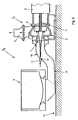
- Figur 1 eine schematisch dargestellte Seitenansicht einer Hebeeinrichtung zum Abpumpen von verunreinigten flüssigen Medien, insbesondere Kühlschmiermittel mit einer Freistromkreiselpumpe;
- Figur 2 eine schematisch dargestellte Seitenansicht auf ein weiteres Ausführungsbeispiel einer weiteren Hebeeinrichtung gemäss Figur 1;
- Figur 3 eine schematisch dargestellte teilweise aufgeschnittene Freistromkreiselpumpe zum Betreiben einer Hebeeinrichtung.
- Gemäss Figur 1 weist eine erfindungsgemässe Hebeeinrichtung R1 eine Freistromkreiselpumpe F1 auf, die in einen Hebebehälter 1 der Hebeeinrichtung R1 einragt.
- Die Freistromkreiselpumpe F1 besitzt eine Antriebseinheit 2, insbesondere Elektromotor, der über eine hier nur angedeutet Antriebswelle 3 ein gestrichelt angedeutetes Flügelrad 4 antreibt. Das Flügelrad 4 sitzt in einem Pumpengehäuse 5, an welches vorzugsweise zentrisch zum Flügelrad 4 in einem unteren Gehäuseteil 6 eine Ansaugöffnung 7 anschliesst.
- Vom Pumpengehäuse 5 wird über die Ansaugöffnung 7 flüssiges Medium, insbesondere Kühlschmiermittel angesaugt und über einen Auslass 8 einer weiteren Verwendung wie bspw. Aufbereitungs- oder Reinigungseinrichtung, Filtereinrichtung etc. zugeführt, damit verunreinigte flüssige Medien, bzw. verunreinigtes Kühlschmiermittel gereinigt werden können und danach wieder einer gleichen oder weiteren Verwendung zugeführt werden kann.
- Zu dem vorliegenden Ausführungsbeispiel ist die Freistromkreiselpumpe F1 in einem Hebebehälter 1 lotrecht eingesetzt, an welchen ein Spülrinne 9 anschliesst.
- Von einem hier nicht näher dargestellten Auffangbecken oder Spülrinne 9 selbst, gelangt verunreinigtes flüssiges Medium, insbesondere Kühlschmiermittel, bestehend aus Emulsionen, Ölen, verschmutzten Medien wie Späne, Abrieb od. dgl., bspw. von verspanenden Bearbeitungsmaschinen, wie Drehzentren, Fräszentren etc. in den Hebebehälter 1.
- Im Hebebehälter 1 sammelt sich im Bereich eines Wannenbodens 10 das Gemisch aus Kühlschmiermittel und Verunreinigungen und wird dort zur weiteren Bearbeitung, insbesondere zur Reinigung mittels der Freistromkreiselpumpe F1 über den Auslass 8 weiter gepumpt bzw. weiter transportiert.
- Bei derartigen Freistromkreiselpumpe F1 ist von Nachteil, dass diese erst einen sehr grossen Füllstand erreichen müssen, bis diese die vollständige Leistung, nach dem Entlüften und Ansaugen von Nebenluft erzielen.
- Bei der vorliegenden Erfindung hat sich als besonderes vorteilhaft erwiesen, an den Wannenboden 10 einen Bypass 11 anzuschliessen, dessen Auslassöffnung 12 vorzugsweise zentrisch zur Ansaugöffnung 7 bzw. zentrisch und in einer gemeinsamen Achse liegend zum Flügelrad 4 der Freistromkreiselpumpe F1 ausgerichtet ist.
- Die Auslassöffnung 12 des Bypasses 11 ist zudem gegenüber im Flügelrad 4 bzw. der Ansaugöffnung 7 der Freistromkreiselpumpe F1 beabstandet.
- Es hat sich bei der vorliegenden Erfindung als besonders vorteilhaft erwiesen, permanent flüssiges Medium, insbesondere Kühlschmiermittel über den Bypass 11 der Freistromkreiselpumpe F1 zuzuführen, so dass sich ein Ansaugen von Nebenluft wesentlich reduzieren lässt, so dass die Freistromkreiselpumpe F1 erheblich schneller auf ihre Maximalleistung kommt und sich ein Mindestfüllstand hierdurch deutlich reduzieren lässt.
- Dabei wird bei der vorliegenden Erfindung über den Bypass 11 Kühlschmiermittel aus dem gesamten System der Freistromkreiselpumpe F1 permanent zugeführt, wobei die Zufuhr unter einem Druck von etwa 0,2 bar bis 3 bar, vorzugsweise 0,5 bar erfolgt. Ferner wird ein Fördervolumen von etwa 5% bis 15%, vorzugsweise 10% der Gesamtfördermenge der Freistromkreiselpumpe F1 dem Bypass 11 zugeführt, um angesaugte Nebenluft zu verdrängen und einen Mindestfüllstand zu reduzieren.
- Auf diese Weise lässt sich ein homogenes Ansaugen von flüssigen Medien, insbesondere Kühlschmiermittel mit Verunreinigungen gewährleisten, ohne dass sich Kühlschmiermittel bzw. das flüssige Medium in der Spülrinne 9 anstaut, bis die Freistromkreiselpumpe F1 entlüftet ist und die Nebenluft aus dieser abgeführt ist. Dies führt zu einem wesentlich homogeneren Bereitstellen von Kühlschmiermitteln.
- In dem Ausführungsbeispiel der vorliegenden Erfindung gemäss Figur 2 ist eine Hebeeinrichtung R2 aufgezeigt, bei welcher eine Freistromkreiselpumpe F2 auf einem Untergrund 13 in einer liegenden Ausführung angeordnet ist. An deren Ansaugöffnung 7 schliesst eine Saugleitung 14 an, die mit der Spülrinne 9 in Verbindung steht.
- Wie in dem Ausführungsbeispiel gemäss Figur 2 angedeutet, schliesst an die Saugleitung 14 ein Bypass 11 an, der in oben beschriebener Weise einen Teilstrom an flüssigem Medium, insbesondere Kühlschmiermittel der Ansaugöffnung 7 bzw. des Flügelrades 4 der Freistromkreiselpumpe F2 zuführt. Vorzugesweise ist die Auslassöffnung 12 bzw. der Bypass 11 auf das Flügelrad 4 zentrisch und in einer Achse liegend ausgerichtet, so dass hierüber in oben beschriebener Weise flüssiges Medium bzw. Kühlschmiermittel der Freistromkreiselpumpe F2 permanent zugeführt werden kann, um zu entlüften bzw. ein Ansaugen von Nebenluft zu vermindern, wobei ein Wirkungsgrad der Freistromkreiselpumpe F1, insbesondere der Hebeeinrichtung R2 wesentlich verbessert wird.
- In dem Ausführungsbeispiel der vorliegenden Erfindung gemäss Figur 3 ist eine Freistromkreiselpumpe F3 herkömmlicher Art aufgezeigt, bei welcher in einem Pumpengehäuse 5, insbesondere in einem unteren Gehäuseteil 6 zumindest eine oder eine Mehrzahl von Bypässen 11 an unterschiedlichen Orten anschliessen bzw. angeschlossen werden können, um in oben beschriebener Weise Nebenluft beim Ansaugen von flüssigem Medium zu reduzieren bzw. die Freistromkreiselpumpe F3 zu entlüften.
- Auf diese Weise lässt sich auch ein Mindestfüllstand zum Betreiben der Freistromkreiselpumpe F3 erheblich reduzieren.
- Ferner soll im Rahmen der vorliegenden Erfindung liegen, dass zusätzlich oberhalb des Flügelrades 4, und oberhalb des Pumpengehäuses 5 in einem Zwischengehäuse 15, insbesondere bei Unterdruck zusätzlich Sperrflüssigkeit, bspw. als reines Kühlschmiermittel über eine separate Zuführleitung 16 zugeführt werden kann, so dass ein Ansaugen von Nebenluft im lagerseitigen Bereich der Antriebswelle 3 zusätzlich vermieden bzw. reduziert wird.
- Dies soll ebenfalls im Rahmen der vorliegenden Erfindung liegen.
- Wichtig ist jedoch bei der vorliegenden Erfindung, dass insbesondere der Bypass 11 vorzugsweise zentrisch vor der Ansaugöffnung 7 der Freistromkreiselpumpe F3 zugeordnet werden kann oder direkt in den unteren Gehäuseteil 6 des Pumpengehäuses 5 einmündet, so dass die Auslassöffnung 12 des Bypasses 11 auf das Flügelrad 4 der Freistromkreiselpumpe F3 ausgerichtet ist. Dabei kann der Bypass 11 im Pumpengehäuse 5 bzw. Gehäuseteil 6 axial, oder radial oder dazwischenliegend axial bis radial auf das Flügelrad 4 ausgerichtet sein. Bevorzugt ist jedoch die Ausführung, dass der Bypass 11 zentrisch und beabstandet vor Ansaugöffnung 7 angeordnet ist.
- Ferner kann auf ein Ansaugverhalten bzw. ein Entlüftungsverhalten Einfluss genommen werden, in dem der Volumenstrom bzw. der Druck des flüssigen Mediums auf den Bypass 11 verändert wird oder ein Abstand zwischen Bypass 11 bzw. Auslassöffnung 12 und Ansaugöffnung 7 verändert bzw. variiert wird. Dies soll ebenfalls im Rahmen der vorliegenden Erfindung liegen.
-
1 Hebebehälter 34 67 2 Antriebseinheit 35 68 3 Antriebswelle 36 69 4 Flügelrad 37 70 5 Pumpengehäuse 38 71 6 Gehäuseteil 39 72 7 Ansaugöffnung 40 73 8 Auslass 41 74 9 Spülrinne 42 75 10 Wannenboden 43 76 11 Bypass 44 77 12 Auslassöffnung 45 78 13 Untergrund 46 79 14 Saugleitung 47 15 Zwischengehäuse 48 R1 Hebeeinrichtung 16 Zuführleitung 49 R2 Hebeeinrichtung 17 50 18 51 19 52 F1 Freistromkreiselpumpe 20 53 F2 Freistromkreiselpumpe 21 54 F3 Freistromkreiselpumpe 22 55 23 56 24 57 25 58 26 59 27 60 28 61 29 62 30 63 31 64 32 65 33 66
Claims (21)
- Verfahren zum Betreiben einer Hebeeinrichtung (R1, R2) zum Abpumpen von verunreinigten flüssigen Medien, wie Kühlschmiermittel unter Verwendung zumindest einer Freistromkreiselpumpe (F1, F2, F3),
dadurch gekennzeichnet,
dass eine Ansaugöffnung (7) der Freistromkreiselpumpe (F1, F2, F3) permanent mit einem flüssigen Medium über einen Bypass (11) beaufschlagt wird, wobei eine Auslassöffnung (12) des Bypasses (11) gegenüber der Ansaugöffnung (7) beabstandet wird, und in etwa 5% bis 15% des Fördervolumens der Freistromkreiselpumpe (F1, F2, F3) über den Bypass (11) auf das Flügelrad (4) zugeführt werden. - Verfahren zum Betreiben einer Hebeleinrichtung (R1, R2) zum Abpumpen von verunreinigten flüssigen Medien, wie Kühlschmiermittel unter Verwendung zumindest einer Freistromkreiselpumpe (F1, F2, F3), dadurch gekennzeichnet, dass ein Ansaugbereich der Freistromkreiselpumpe (F1, F2, F3) permanent mit einem flüssigen Medium über einen Bypass (11) beaufschlagt wird, wobei über eine Auslassöffnung (12) des Bypasses (11) gegenüber dem Ansaugbereich der Freistromkreiselpumpe (F1, F2, F3) beabstandet wird, und der Bypass (11) in etwa mittig und beabstandet vor der Ansaugöffnung (7) angeordnet wird, und das flüssige Medium aus dem Bypass (11) in etwa lotrecht auf das Flügelrad (4) der Freistromkreiselpumpe (F1, F2, F3) beaufschlagt oder beschleunigt wird.
- Verfahren nach Anspruch 1 oder 2, dadurch gekennzeichnet, dass als flüssiges Medium Kühlschmiermittel, über einen Bypass (11) die Ansaugöffnung (7) oder den Ansaugbereich, insbesondere den Bereich des Flügelrades (4) der Freistromkreiselpumpe (F1, F2, F3) anströmt.
- Verfahren nach wenigstens einem der Ansprüche 1 bis 3, dadurch gekennzeichnet, dass eine Auslassöffnung (12) des Bypasses (11) zu einer Ansaugöffnung (7) beabstandet angeordnet wird, so dass ein Teil des flüssigen Mediums, permanent das Flügelrad (4) der Freistromkreiselpumpe (F1, F2, F3) beaufschlagt bzw. anströmt.
- Verfahren nach Anspruch 3 oder 4, dadurch gekennzeichnet, dass der Bypass (11) in einem Gehäuseteil (6) der Freistromkreiselpumpe (F1, F2, F3) nahe des Flügelrades (4) einmündet.
- Verfahren nach wenigstens einem der Ansprüche 1 bis 5, dadurch gekennzeichnet, dass vorzugsweise 10% des Fördervolumens der Freistromkreiselpumpe (F1, F2, F3) über den Bypass (11) auf das Flügelrad (4) zugeführt werden.
- Verfahren nach wenigstens einem der Ansprüche 3 bis 6, dadurch gekennzeichnet, dass das flüssige Medium, insbesondere des Kühlschmiermittel mit etwa 0,2 bar bits 3 bar, insbesondere 0,5 bar Druck aus dem Bypass (11) auf das Flügelrad (4), die, Ansaugöffnung (7) oder den Ansaugbereich der Freistromkreiselpumpe (F1, F2, F3) beaufschlagt werden.
- Verfahren nach wenigstens einem der Ansprüche 3 bis 7, dadurch gekennzeichnet, dass der Bypass (11) bei einer senkrechten Anordnung der Freistromkreiselpumpe (F1, F3) in einem Wannenboden (10) der Hebeeinrichtung (R1, R2) und bei einer liegenden Anordnung der Freistromkreiselpumpe (F2) in eine Saugleitung (14) der Hebeeinrichtung (R1, R2) einmündet.
- Verfahren nach wenigstens einem der Ansprüche 1 bis 8, dadurch gekennzeichnet, dass antriebswellenseitig oberhalb des Flügelrades. (4) bei Unterdruck in der Freistromkreiselpumpe (F1, F2, F3) Sperrflüssigkeit zusätzlich zugeführt wird.
- Hebeeinrichtung zum Abpumpen von verunreinigten flüssigen Medien, wie Kühlschmiermittel mit zumindest einer Freistromkreiselpumpe (F1, F2, F3), dadurch gekennzeichnet, dass über zumindest einen Bypass (11) eine Ansaugöffnung (7) oder ein Ansaugbereich der Freistromkreiselpumpe (F1, F2, F3) mit flüssigem Medium beaufschlagbar ist, wobei eine Auslassöffnung (12) des Bypasses (11) gegenüber der Ansaugöffnung (7) oder dem Ansaugbereich der Freistromkreiselpumpe (F1, F2, F3) beabstandet ist und durch den Bypass (11) ein Fördervolumen an flüssigem Medium von etwa 5% bis 15% des Fördervolumens der. Freistromkreiselpumpe (F1, F2, F3), zuführbar ist.
- Hebeeinrichtung nach Anspruch 10, dadurch gekennzeichnet, dass der Bypass (11) in einem Gehäuseteil (6) der Freistromkreiselpumpe (F1, F2, F3) angeordnet ist, und eine Auslassöffnung (12) des Bypasses (11) auf das Flügelrad (4) der Freistromkreiselpumpe (F1, F2, F3) ausgerichtet ist.
- Hebeeinrichtung nach Anspruch 10 oder 11, dadurch gekennzeichnet, dass der Bypass (11) im Bereich eines Wannenbodens (10) vorgesehen ist, und auf Flügelrad (4) der Freistromkreiselpumpe (F1, F2, F3) ausgerichtet ist, wobei eine Auslassöffnung (12) des Bypasses (11) zur Ansaugöffnung (7) der Freistromkreiselpumpe (F1, F2, F3) beabstandet, insbesondere höhenverstellbar ist.
- Hebeeinrichtung nach wenigstens einem der Ansprüche 10 bis 12, dadurch gekennzeichnet, dass zumindest ein Bypass (11) an eine an den Ansaugbereich anschliessende Saugleitung (14) der Freistromkreiselpumpe (F2) bei einer liegenden Bauweise einmündet, wobei eine Auslassöffnung (12) des Bypasses (11) vorzugsweise mittig auf das Flügelrad (4) der Freistromkreiselpumpe (F2) ausgerichtet ist.
- Hebeeinrichtung nach wenigstens einem der Ansprüche 10 bis 13, dadurch gekennzeichnet, dass zumindest ein Bypass (11) in einem Gehäuseteil (6) nahe des Flügelrades (4) der Freistromkreiselpumpe (F1, F2, F3) anschliesst, und die Auslassöffnung (12) des Bypasses (11) auf das Flügelrad (4) axial bis radial ausgerichtet ist.
- Hebeeinrichtung nach wenigstens einem der Ansprüche 10 bis 14, dadurch gekennzeichnet, dass das flüssige Medium, insbesondere Kühlschmiermittel mit einem Druck von 0,2 bar bis 3 bar, insbesondere 1 bar, zuführbar ist.
- Hebeeinrichtung nach wenigstens einem der Ansprüche 10 bis 15, dadurch gekennzeichnet, dass durch den Bypass (11) ein Fördervolumen an flüssigem Medium, insbesondere Kühlschmiermittel, von etwa 5% bis 15%, insbesondere 10% des Fördervolumens der Freistromkreiselpumpe (F1, F2, F3) zuführbar ist.
- Hebeeinrichtung nach wenigstens einem der Ansprüche 11 bis 17, dadurch gekennzeichnet, dass der. Freistromkreiselpumpe (F1, F2, F3) oberhalb des Flügelrades (4) eine Zuführleitung (16), die in ein Zwischengehäuse (15) einmündet, über welche Sperrflüssigkeit bei Unterdruckbetrieb zuführbar ist.
- Freistromkreiselpumpe zum Abpumpen von verunreinigten flüssigen Medien, wie Kühlschmiermittel, mit einem Flügelrad (4) und einer Ansaugöffnung (7), dadurch gekennzeichnet, dass der Ansaugöffnung (7), dem Ansaugbereich oder dem Flügelrad (4) über zumindest einen Bypass (11) zusätzlich flüssiges Medium zuführbar ist, wobei eine Auslassöffnung (12) des Bypasses (11) gegenüber der Ansaugöffnung (7), oder dem Ansaugbereich der Freistromkreiselpumpe (F1, F2, F3) beabstandet ist, und der Bypass (11) ausserhalb einer Ansaugöffnung (7), zu dieser beabstandet ausgerichtet ist, wobei eine Öffnung des Bypasses (11) in etwa lotrecht und zentrisch in einer Achse liegend auf das Flügelrad (4) axial ausgerichtet ist.
- Freistromkreiselpümpe nach Anspruch 18, dadurch gekennzeichnet, dass der Bypass (11) in ein Gehäuseteil (6) einmündet und eine Auslassöffnung (12) des Bypasses (11) axial, radial, sowie axial bis radial auf ein Flügelrad (4) ausgerichtet ist.
- Freistromkreiselpumpe nach wenigstens einem Ansprüche 18 und 19, dadurch gekennzeichnet, dass über den Bypass (11) flüssiges Medium, insbesondere Kühlschmiermittel mit 0,2 bar bis 3 bar, insbesondere 1 bar Druck dem Flügelrad (4) zuführbar ist.
- Freistromkreiselpumpe nach wenigstens einem der Ansprüche 18 bis 21, dadurch gekennzeichnet, dass über den Bypass (11) in etwa 5% bis 15%, insbesondere 10% des Gesamtfördervolumens der Freistromkreiselpumpe (F1, F2, F3) dem Flügelrad (4) zuführbar sind.
Priority Applications (1)
| Application Number | Priority Date | Filing Date | Title |
|---|---|---|---|
| PL04022303T PL1522734T3 (pl) | 2003-10-08 | 2004-09-20 | Sposób eksploatacji zbiorczego urządzenia do odpompowania zanieczyszczonych ciekłych mediów, zwłaszcza cieczy chłodząco-smarującej |
Applications Claiming Priority (2)
| Application Number | Priority Date | Filing Date | Title |
|---|---|---|---|
| DE10347261 | 2003-10-08 | ||
| DE10347261A DE10347261A1 (de) | 2003-10-08 | 2003-10-08 | Verfahren zum Betreiben einer Hebeeinrichtung zum Abpumpen von verunreinigten flüssigen Medien, insbesondere Kühlschmiermitteln |
Publications (2)
| Publication Number | Publication Date |
|---|---|
| EP1522734A1 EP1522734A1 (de) | 2005-04-13 |
| EP1522734B1 true EP1522734B1 (de) | 2007-09-19 |
Family
ID=34306370
Family Applications (1)
| Application Number | Title | Priority Date | Filing Date |
|---|---|---|---|
| EP04022303A Expired - Lifetime EP1522734B1 (de) | 2003-10-08 | 2004-09-20 | Verfahren zum Betreiben einer Hebeeinrichtung zum Abpumpen von verunreinigten flüssigen Medien, insbesondere Kühlschmiermittel |
Country Status (4)
| Country | Link |
|---|---|
| EP (1) | EP1522734B1 (de) |
| AT (1) | ATE373780T1 (de) |
| DE (2) | DE10347261A1 (de) |
| PL (1) | PL1522734T3 (de) |
Family Cites Families (9)
| Publication number | Priority date | Publication date | Assignee | Title |
|---|---|---|---|---|
| DE1034033B (de) * | 1956-01-05 | 1958-07-10 | Karl Wernert | Pumpenanlage mit einer oberhalb des Fluessigkeitsspiegels angeordneten Kreiselpumpe |
| FR1403881A (fr) * | 1964-05-15 | 1965-06-25 | Worthington | Pompe rotative équipée d'un dispositif d'alimentation forcée |
| US4188172A (en) * | 1978-05-24 | 1980-02-12 | The United States Of America As Represented By The Secretary Of The Navy | Method and means for injecting hot liquid when pumping cold liquid |
| US4792275A (en) * | 1986-12-24 | 1988-12-20 | Eddy Pump Corporation | Pump construction |
| US5114312A (en) * | 1990-06-15 | 1992-05-19 | Atsco, Inc. | Slurry pump apparatus including fluid housing |
| DE9213913U1 (de) * | 1992-10-15 | 1993-01-14 | Scheible Versorgungsanlagen GmbH, 7340 Geislingen | Vorrichtung zum Entsorgen von flüssigen Medien |
| DE19804907C1 (de) * | 1998-02-07 | 1999-07-15 | Brinkmann Pumpen K H Brinkmann | Kreiselpumpe mit entlüfteter Pumpenkammer |
| DE19962729A1 (de) * | 1999-12-23 | 2001-07-05 | Grundfos As | Selbstansaugendes Pumpenaggregat |
| DE10118525B4 (de) * | 2001-04-14 | 2005-03-17 | Brinkmann Pumpen K.H. Brinkmann Gmbh & Co. Kg | Vorrichtung zum Absaugen von Kühlschmierstoff aus einem Sammelbecken |
-
2003
- 2003-10-08 DE DE10347261A patent/DE10347261A1/de not_active Withdrawn
-
2004
- 2004-09-20 DE DE502004005002T patent/DE502004005002D1/de not_active Expired - Lifetime
- 2004-09-20 AT AT04022303T patent/ATE373780T1/de active
- 2004-09-20 EP EP04022303A patent/EP1522734B1/de not_active Expired - Lifetime
- 2004-09-20 PL PL04022303T patent/PL1522734T3/pl unknown
Also Published As
| Publication number | Publication date |
|---|---|
| ATE373780T1 (de) | 2007-10-15 |
| EP1522734A1 (de) | 2005-04-13 |
| PL1522734T3 (pl) | 2008-02-29 |
| DE502004005002D1 (de) | 2007-10-31 |
| DE10347261A1 (de) | 2005-05-04 |
Similar Documents
| Publication | Publication Date | Title |
|---|---|---|
| DE19781894B4 (de) | Selbstansaugende Kreiselpumpe | |
| DE4212169A1 (de) | Sperrsystem fuer das schmieroel der lager eines in einer begrenzten umgebung angeordneten zentrifugalkompressors mit labyrinthdichtungen | |
| DE3015211A1 (de) | Schutzeinrichtung fuer unterwassermotoren | |
| DE3705912C2 (de) | ||
| DE4327506C2 (de) | Turbovakuumpumpe | |
| DE1653664B2 (de) | Anordnung zur foerderung von schmieroel | |
| DE69303447T2 (de) | Vakuumpumpgerät | |
| EP0459107B1 (de) | Drehschiebervakuumpumpe und ihr Verfahren zur Ölversorgung | |
| DE4327583A1 (de) | Vakuumpumpe mit Ölabscheider | |
| DE2048301A1 (de) | Meß- und Spulolpumpe | |
| DE3701562C2 (de) | Kreiselpumpe mit Spaltrohrmotor | |
| WO2011091809A1 (de) | Gartenpumpenanordnung | |
| DE202004015599U1 (de) | Vakuumpumpensystem mit mehreren Pumpen | |
| DE19905435B4 (de) | Tauchpumpe | |
| DE10341998A1 (de) | Vorrichtung und Verfahren zur Oberflächenbehandlung von Werkstücken in einem Kreislaufsystem | |
| DE10309438B3 (de) | Kreiselpumpe mit entlüfteter Pumpenkammer | |
| DE3141080C2 (de) | "Selbstansaugende Kreiselpumpe" | |
| EP1522734A1 (de) | Verfahren zum Betreiben einer Hebeeinrichtung zum Abpumpen von verunreinigten flüssigen Medien, insbesondere Kühlschmiermittel | |
| DE29514402U1 (de) | Vorrichtung zum Verbessern des Ansaugverhaltens von Strömungsförderpumpen | |
| EP3978760B1 (de) | Tauchkreiselpumpe | |
| DE4325549C2 (de) | Kreiselpumpe | |
| DE490265C (de) | Einrichtung an Kreisel- und Kolbenpumpen zur Foerderung grob verunreinigter Fluessigkeiten | |
| EP3945218A1 (de) | Kreiselpumpe | |
| DE102017119019A1 (de) | Verfahren zum Behandeln einer spänebelasteten Flüssigkeit | |
| DE10296521B4 (de) | Pumpvorrichtung |
Legal Events
| Date | Code | Title | Description |
|---|---|---|---|
| PUAI | Public reference made under article 153(3) epc to a published international application that has entered the european phase |
Free format text: ORIGINAL CODE: 0009012 |
|
| AK | Designated contracting states |
Kind code of ref document: A1 Designated state(s): AT BE BG CH CY CZ DE DK EE ES FI FR GB GR HU IE IT LI LU MC NL PL PT RO SE SI SK TR |
|
| AX | Request for extension of the european patent |
Extension state: AL HR LT LV MK |
|
| 17P | Request for examination filed |
Effective date: 20050429 |
|
| AKX | Designation fees paid |
Designated state(s): AT BE BG CH CY CZ DE DK EE ES FI FR GB GR HU IE IT LI LU MC NL PL PT RO SE SI SK TR |
|
| GRAP | Despatch of communication of intention to grant a patent |
Free format text: ORIGINAL CODE: EPIDOSNIGR1 |
|
| GRAS | Grant fee paid |
Free format text: ORIGINAL CODE: EPIDOSNIGR3 |
|
| GRAA | (expected) grant |
Free format text: ORIGINAL CODE: 0009210 |
|
| AK | Designated contracting states |
Kind code of ref document: B1 Designated state(s): AT BE BG CH CY CZ DE DK EE ES FI FR GB GR HU IE IT LI LU MC NL PL PT RO SE SI SK TR |
|
| REG | Reference to a national code |
Ref country code: GB Ref legal event code: FG4D Free format text: NOT ENGLISH |
|
| REG | Reference to a national code |
Ref country code: CH Ref legal event code: EP |
|
| REG | Reference to a national code |
Ref country code: CH Ref legal event code: NV Representative=s name: ARIE WUBBEN |
|
| REF | Corresponds to: |
Ref document number: 502004005002 Country of ref document: DE Date of ref document: 20071031 Kind code of ref document: P |
|
| REG | Reference to a national code |
Ref country code: IE Ref legal event code: FG4D Free format text: LANGUAGE OF EP DOCUMENT: GERMAN |
|
| REG | Reference to a national code |
Ref country code: SE Ref legal event code: TRGR |
|
| PG25 | Lapsed in a contracting state [announced via postgrant information from national office to epo] |
Ref country code: FI Free format text: LAPSE BECAUSE OF FAILURE TO SUBMIT A TRANSLATION OF THE DESCRIPTION OR TO PAY THE FEE WITHIN THE PRESCRIBED TIME-LIMIT Effective date: 20070919 |
|
| REG | Reference to a national code |
Ref country code: PL Ref legal event code: T3 |
|
| NLV1 | Nl: lapsed or annulled due to failure to fulfill the requirements of art. 29p and 29m of the patents act | ||
| ET | Fr: translation filed | ||
| BERE | Be: lapsed |
Owner name: BAR + CO.-ANLAGENTECHNIK G.M.B.H. Effective date: 20070930 |
|
| PG25 | Lapsed in a contracting state [announced via postgrant information from national office to epo] |
Ref country code: MC Free format text: LAPSE BECAUSE OF NON-PAYMENT OF DUE FEES Effective date: 20070930 Ref country code: GR Free format text: LAPSE BECAUSE OF FAILURE TO SUBMIT A TRANSLATION OF THE DESCRIPTION OR TO PAY THE FEE WITHIN THE PRESCRIBED TIME-LIMIT Effective date: 20071220 Ref country code: NL Free format text: LAPSE BECAUSE OF FAILURE TO SUBMIT A TRANSLATION OF THE DESCRIPTION OR TO PAY THE FEE WITHIN THE PRESCRIBED TIME-LIMIT Effective date: 20070919 Ref country code: ES Free format text: LAPSE BECAUSE OF FAILURE TO SUBMIT A TRANSLATION OF THE DESCRIPTION OR TO PAY THE FEE WITHIN THE PRESCRIBED TIME-LIMIT Effective date: 20071230 |
|
| REG | Reference to a national code |
Ref country code: IE Ref legal event code: FD4D |
|
| REG | Reference to a national code |
Ref country code: HU Ref legal event code: AG4A Ref document number: E002802 Country of ref document: HU |
|
| PG25 | Lapsed in a contracting state [announced via postgrant information from national office to epo] |
Ref country code: PT Free format text: LAPSE BECAUSE OF FAILURE TO SUBMIT A TRANSLATION OF THE DESCRIPTION OR TO PAY THE FEE WITHIN THE PRESCRIBED TIME-LIMIT Effective date: 20080219 Ref country code: GB Free format text: LAPSE BECAUSE OF FAILURE TO SUBMIT A TRANSLATION OF THE DESCRIPTION OR TO PAY THE FEE WITHIN THE PRESCRIBED TIME-LIMIT Effective date: 20070919 Ref country code: SK Free format text: LAPSE BECAUSE OF FAILURE TO SUBMIT A TRANSLATION OF THE DESCRIPTION OR TO PAY THE FEE WITHIN THE PRESCRIBED TIME-LIMIT Effective date: 20070919 |
|
| PG25 | Lapsed in a contracting state [announced via postgrant information from national office to epo] |
Ref country code: RO Free format text: LAPSE BECAUSE OF FAILURE TO SUBMIT A TRANSLATION OF THE DESCRIPTION OR TO PAY THE FEE WITHIN THE PRESCRIBED TIME-LIMIT Effective date: 20070919 |
|
| PLBE | No opposition filed within time limit |
Free format text: ORIGINAL CODE: 0009261 |
|
| STAA | Information on the status of an ep patent application or granted ep patent |
Free format text: STATUS: NO OPPOSITION FILED WITHIN TIME LIMIT |
|
| PG25 | Lapsed in a contracting state [announced via postgrant information from national office to epo] |
Ref country code: DK Free format text: LAPSE BECAUSE OF FAILURE TO SUBMIT A TRANSLATION OF THE DESCRIPTION OR TO PAY THE FEE WITHIN THE PRESCRIBED TIME-LIMIT Effective date: 20070919 |
|
| 26N | No opposition filed |
Effective date: 20080620 |
|
| PG25 | Lapsed in a contracting state [announced via postgrant information from national office to epo] |
Ref country code: BE Free format text: LAPSE BECAUSE OF NON-PAYMENT OF DUE FEES Effective date: 20070930 |
|
| PG25 | Lapsed in a contracting state [announced via postgrant information from national office to epo] |
Ref country code: IE Free format text: LAPSE BECAUSE OF FAILURE TO SUBMIT A TRANSLATION OF THE DESCRIPTION OR TO PAY THE FEE WITHIN THE PRESCRIBED TIME-LIMIT Effective date: 20070919 |
|
| PG25 | Lapsed in a contracting state [announced via postgrant information from national office to epo] |
Ref country code: EE Free format text: LAPSE BECAUSE OF FAILURE TO SUBMIT A TRANSLATION OF THE DESCRIPTION OR TO PAY THE FEE WITHIN THE PRESCRIBED TIME-LIMIT Effective date: 20070919 |
|
| PG25 | Lapsed in a contracting state [announced via postgrant information from national office to epo] |
Ref country code: SI Free format text: LAPSE BECAUSE OF FAILURE TO SUBMIT A TRANSLATION OF THE DESCRIPTION OR TO PAY THE FEE WITHIN THE PRESCRIBED TIME-LIMIT Effective date: 20070919 |
|
| PG25 | Lapsed in a contracting state [announced via postgrant information from national office to epo] |
Ref country code: CY Free format text: LAPSE BECAUSE OF FAILURE TO SUBMIT A TRANSLATION OF THE DESCRIPTION OR TO PAY THE FEE WITHIN THE PRESCRIBED TIME-LIMIT Effective date: 20070919 |
|
| PG25 | Lapsed in a contracting state [announced via postgrant information from national office to epo] |
Ref country code: LU Free format text: LAPSE BECAUSE OF NON-PAYMENT OF DUE FEES Effective date: 20070920 Ref country code: BG Free format text: LAPSE BECAUSE OF FAILURE TO SUBMIT A TRANSLATION OF THE DESCRIPTION OR TO PAY THE FEE WITHIN THE PRESCRIBED TIME-LIMIT Effective date: 20071219 |
|
| PG25 | Lapsed in a contracting state [announced via postgrant information from national office to epo] |
Ref country code: TR Free format text: LAPSE BECAUSE OF FAILURE TO SUBMIT A TRANSLATION OF THE DESCRIPTION OR TO PAY THE FEE WITHIN THE PRESCRIBED TIME-LIMIT Effective date: 20070919 |
|
| PGFP | Annual fee paid to national office [announced via postgrant information from national office to epo] |
Ref country code: AT Payment date: 20100923 Year of fee payment: 7 |
|
| PGFP | Annual fee paid to national office [announced via postgrant information from national office to epo] |
Ref country code: CH Payment date: 20101014 Year of fee payment: 7 Ref country code: HU Payment date: 20101022 Year of fee payment: 7 |
|
| PGFP | Annual fee paid to national office [announced via postgrant information from national office to epo] |
Ref country code: CZ Payment date: 20110913 Year of fee payment: 8 Ref country code: SE Payment date: 20110923 Year of fee payment: 8 Ref country code: PL Payment date: 20110823 Year of fee payment: 8 |
|
| REG | Reference to a national code |
Ref country code: CH Ref legal event code: PL |
|
| PG25 | Lapsed in a contracting state [announced via postgrant information from national office to epo] |
Ref country code: HU Free format text: LAPSE BECAUSE OF NON-PAYMENT OF DUE FEES Effective date: 20110921 Ref country code: LI Free format text: LAPSE BECAUSE OF NON-PAYMENT OF DUE FEES Effective date: 20110930 Ref country code: CH Free format text: LAPSE BECAUSE OF NON-PAYMENT OF DUE FEES Effective date: 20110930 |
|
| REG | Reference to a national code |
Ref country code: AT Ref legal event code: MM01 Ref document number: 373780 Country of ref document: AT Kind code of ref document: T Effective date: 20110920 |
|
| PGFP | Annual fee paid to national office [announced via postgrant information from national office to epo] |
Ref country code: IT Payment date: 20120924 Year of fee payment: 9 |
|
| PG25 | Lapsed in a contracting state [announced via postgrant information from national office to epo] |
Ref country code: AT Free format text: LAPSE BECAUSE OF NON-PAYMENT OF DUE FEES Effective date: 20110920 |
|
| PGFP | Annual fee paid to national office [announced via postgrant information from national office to epo] |
Ref country code: FR Payment date: 20121010 Year of fee payment: 9 |
|
| PG25 | Lapsed in a contracting state [announced via postgrant information from national office to epo] |
Ref country code: CZ Free format text: LAPSE BECAUSE OF NON-PAYMENT OF DUE FEES Effective date: 20120920 Ref country code: SE Free format text: LAPSE BECAUSE OF NON-PAYMENT OF DUE FEES Effective date: 20120921 |
|
| REG | Reference to a national code |
Ref country code: SE Ref legal event code: EUG |
|
| PG25 | Lapsed in a contracting state [announced via postgrant information from national office to epo] |
Ref country code: PL Free format text: LAPSE BECAUSE OF NON-PAYMENT OF DUE FEES Effective date: 20120920 |
|
| REG | Reference to a national code |
Ref country code: PL Ref legal event code: LAPE |
|
| REG | Reference to a national code |
Ref country code: FR Ref legal event code: ST Effective date: 20140530 |
|
| PG25 | Lapsed in a contracting state [announced via postgrant information from national office to epo] |
Ref country code: IT Free format text: LAPSE BECAUSE OF NON-PAYMENT OF DUE FEES Effective date: 20130920 Ref country code: FR Free format text: LAPSE BECAUSE OF NON-PAYMENT OF DUE FEES Effective date: 20130930 |
|
| REG | Reference to a national code |
Ref country code: DE Ref legal event code: R082 Ref document number: 502004005002 Country of ref document: DE Representative=s name: PATENTANWAELTE UND RECHTSANWALT DR. WEISS, ARA, DE Ref country code: DE Ref legal event code: R082 Ref document number: 502004005002 Country of ref document: DE Representative=s name: PATENTANWAELTE UND RECHTSANWALT WEISS, ARAT & , DE |
|
| PGFP | Annual fee paid to national office [announced via postgrant information from national office to epo] |
Ref country code: DE Payment date: 20161129 Year of fee payment: 13 |
|
| REG | Reference to a national code |
Ref country code: DE Ref legal event code: R119 Ref document number: 502004005002 Country of ref document: DE |
|
| PG25 | Lapsed in a contracting state [announced via postgrant information from national office to epo] |
Ref country code: DE Free format text: LAPSE BECAUSE OF NON-PAYMENT OF DUE FEES Effective date: 20180404 |