EP3944997B1 - Fahrzeugbremsanlage und landwirtschaftliches zugfahrzeug - Google Patents
Fahrzeugbremsanlage und landwirtschaftliches zugfahrzeug Download PDFInfo
- Publication number
- EP3944997B1 EP3944997B1 EP21187706.3A EP21187706A EP3944997B1 EP 3944997 B1 EP3944997 B1 EP 3944997B1 EP 21187706 A EP21187706 A EP 21187706A EP 3944997 B1 EP3944997 B1 EP 3944997B1
- Authority
- EP
- European Patent Office
- Prior art keywords
- connection
- valve device
- configuration
- actuating
- master cylinder
- Prior art date
- Legal status (The legal status is an assumption and is not a legal conclusion. Google has not performed a legal analysis and makes no representation as to the accuracy of the status listed.)
- Active
Links
Images


Classifications
-
- B—PERFORMING OPERATIONS; TRANSPORTING
- B60—VEHICLES IN GENERAL
- B60T—VEHICLE BRAKE CONTROL SYSTEMS OR PARTS THEREOF; BRAKE CONTROL SYSTEMS OR PARTS THEREOF, IN GENERAL; ARRANGEMENT OF BRAKING ELEMENTS ON VEHICLES IN GENERAL; PORTABLE DEVICES FOR PREVENTING UNWANTED MOVEMENT OF VEHICLES; VEHICLE MODIFICATIONS TO FACILITATE COOLING OF BRAKES
- B60T13/00—Transmitting braking action from initiating means to ultimate brake actuator with power assistance or drive; Brake systems incorporating such transmitting means, e.g. air-pressure brake systems
- B60T13/10—Transmitting braking action from initiating means to ultimate brake actuator with power assistance or drive; Brake systems incorporating such transmitting means, e.g. air-pressure brake systems with fluid assistance, drive, or release
- B60T13/12—Transmitting braking action from initiating means to ultimate brake actuator with power assistance or drive; Brake systems incorporating such transmitting means, e.g. air-pressure brake systems with fluid assistance, drive, or release the fluid being liquid
- B60T13/14—Transmitting braking action from initiating means to ultimate brake actuator with power assistance or drive; Brake systems incorporating such transmitting means, e.g. air-pressure brake systems with fluid assistance, drive, or release the fluid being liquid using accumulators or reservoirs fed by pumps
- B60T13/142—Systems with master cylinder
- B60T13/145—Master cylinder integrated or hydraulically coupled with booster
- B60T13/146—Part of the system directly actuated by booster pressure
-
- B—PERFORMING OPERATIONS; TRANSPORTING
- B60—VEHICLES IN GENERAL
- B60T—VEHICLE BRAKE CONTROL SYSTEMS OR PARTS THEREOF; BRAKE CONTROL SYSTEMS OR PARTS THEREOF, IN GENERAL; ARRANGEMENT OF BRAKING ELEMENTS ON VEHICLES IN GENERAL; PORTABLE DEVICES FOR PREVENTING UNWANTED MOVEMENT OF VEHICLES; VEHICLE MODIFICATIONS TO FACILITATE COOLING OF BRAKES
- B60T13/00—Transmitting braking action from initiating means to ultimate brake actuator with power assistance or drive; Brake systems incorporating such transmitting means, e.g. air-pressure brake systems
- B60T13/10—Transmitting braking action from initiating means to ultimate brake actuator with power assistance or drive; Brake systems incorporating such transmitting means, e.g. air-pressure brake systems with fluid assistance, drive, or release
- B60T13/12—Transmitting braking action from initiating means to ultimate brake actuator with power assistance or drive; Brake systems incorporating such transmitting means, e.g. air-pressure brake systems with fluid assistance, drive, or release the fluid being liquid
- B60T13/14—Transmitting braking action from initiating means to ultimate brake actuator with power assistance or drive; Brake systems incorporating such transmitting means, e.g. air-pressure brake systems with fluid assistance, drive, or release the fluid being liquid using accumulators or reservoirs fed by pumps
- B60T13/142—Systems with master cylinder
-
- B—PERFORMING OPERATIONS; TRANSPORTING
- B60—VEHICLES IN GENERAL
- B60T—VEHICLE BRAKE CONTROL SYSTEMS OR PARTS THEREOF; BRAKE CONTROL SYSTEMS OR PARTS THEREOF, IN GENERAL; ARRANGEMENT OF BRAKING ELEMENTS ON VEHICLES IN GENERAL; PORTABLE DEVICES FOR PREVENTING UNWANTED MOVEMENT OF VEHICLES; VEHICLE MODIFICATIONS TO FACILITATE COOLING OF BRAKES
- B60T13/00—Transmitting braking action from initiating means to ultimate brake actuator with power assistance or drive; Brake systems incorporating such transmitting means, e.g. air-pressure brake systems
- B60T13/10—Transmitting braking action from initiating means to ultimate brake actuator with power assistance or drive; Brake systems incorporating such transmitting means, e.g. air-pressure brake systems with fluid assistance, drive, or release
- B60T13/12—Transmitting braking action from initiating means to ultimate brake actuator with power assistance or drive; Brake systems incorporating such transmitting means, e.g. air-pressure brake systems with fluid assistance, drive, or release the fluid being liquid
- B60T13/14—Transmitting braking action from initiating means to ultimate brake actuator with power assistance or drive; Brake systems incorporating such transmitting means, e.g. air-pressure brake systems with fluid assistance, drive, or release the fluid being liquid using accumulators or reservoirs fed by pumps
- B60T13/148—Arrangements for pressure supply
-
- B—PERFORMING OPERATIONS; TRANSPORTING
- B60—VEHICLES IN GENERAL
- B60T—VEHICLE BRAKE CONTROL SYSTEMS OR PARTS THEREOF; BRAKE CONTROL SYSTEMS OR PARTS THEREOF, IN GENERAL; ARRANGEMENT OF BRAKING ELEMENTS ON VEHICLES IN GENERAL; PORTABLE DEVICES FOR PREVENTING UNWANTED MOVEMENT OF VEHICLES; VEHICLE MODIFICATIONS TO FACILITATE COOLING OF BRAKES
- B60T13/00—Transmitting braking action from initiating means to ultimate brake actuator with power assistance or drive; Brake systems incorporating such transmitting means, e.g. air-pressure brake systems
- B60T13/10—Transmitting braking action from initiating means to ultimate brake actuator with power assistance or drive; Brake systems incorporating such transmitting means, e.g. air-pressure brake systems with fluid assistance, drive, or release
- B60T13/66—Electrical control in fluid-pressure brake systems
- B60T13/662—Electrical control in fluid-pressure brake systems characterised by specified functions of the control system components
-
- B—PERFORMING OPERATIONS; TRANSPORTING
- B60—VEHICLES IN GENERAL
- B60T—VEHICLE BRAKE CONTROL SYSTEMS OR PARTS THEREOF; BRAKE CONTROL SYSTEMS OR PARTS THEREOF, IN GENERAL; ARRANGEMENT OF BRAKING ELEMENTS ON VEHICLES IN GENERAL; PORTABLE DEVICES FOR PREVENTING UNWANTED MOVEMENT OF VEHICLES; VEHICLE MODIFICATIONS TO FACILITATE COOLING OF BRAKES
- B60T13/00—Transmitting braking action from initiating means to ultimate brake actuator with power assistance or drive; Brake systems incorporating such transmitting means, e.g. air-pressure brake systems
- B60T13/10—Transmitting braking action from initiating means to ultimate brake actuator with power assistance or drive; Brake systems incorporating such transmitting means, e.g. air-pressure brake systems with fluid assistance, drive, or release
- B60T13/66—Electrical control in fluid-pressure brake systems
- B60T13/68—Electrical control in fluid-pressure brake systems by electrically-controlled valves
- B60T13/686—Electrical control in fluid-pressure brake systems by electrically-controlled valves in hydraulic systems or parts thereof
-
- B—PERFORMING OPERATIONS; TRANSPORTING
- B60—VEHICLES IN GENERAL
- B60T—VEHICLE BRAKE CONTROL SYSTEMS OR PARTS THEREOF; BRAKE CONTROL SYSTEMS OR PARTS THEREOF, IN GENERAL; ARRANGEMENT OF BRAKING ELEMENTS ON VEHICLES IN GENERAL; PORTABLE DEVICES FOR PREVENTING UNWANTED MOVEMENT OF VEHICLES; VEHICLE MODIFICATIONS TO FACILITATE COOLING OF BRAKES
- B60T8/00—Arrangements for adjusting wheel-braking force to meet varying vehicular or ground-surface conditions, e.g. limiting or varying distribution of braking force
- B60T8/32—Arrangements for adjusting wheel-braking force to meet varying vehicular or ground-surface conditions, e.g. limiting or varying distribution of braking force responsive to a speed condition, e.g. acceleration or deceleration
- B60T8/34—Arrangements for adjusting wheel-braking force to meet varying vehicular or ground-surface conditions, e.g. limiting or varying distribution of braking force responsive to a speed condition, e.g. acceleration or deceleration having a fluid pressure regulator responsive to a speed condition
- B60T8/40—Arrangements for adjusting wheel-braking force to meet varying vehicular or ground-surface conditions, e.g. limiting or varying distribution of braking force responsive to a speed condition, e.g. acceleration or deceleration having a fluid pressure regulator responsive to a speed condition comprising an additional fluid circuit including fluid pressurising means for modifying the pressure of the braking fluid, e.g. including wheel driven pumps for detecting a speed condition, or pumps which are controlled by means independent of the braking system
- B60T8/4031—Pump units characterised by their construction or mounting
-
- B—PERFORMING OPERATIONS; TRANSPORTING
- B60—VEHICLES IN GENERAL
- B60T—VEHICLE BRAKE CONTROL SYSTEMS OR PARTS THEREOF; BRAKE CONTROL SYSTEMS OR PARTS THEREOF, IN GENERAL; ARRANGEMENT OF BRAKING ELEMENTS ON VEHICLES IN GENERAL; PORTABLE DEVICES FOR PREVENTING UNWANTED MOVEMENT OF VEHICLES; VEHICLE MODIFICATIONS TO FACILITATE COOLING OF BRAKES
- B60T8/00—Arrangements for adjusting wheel-braking force to meet varying vehicular or ground-surface conditions, e.g. limiting or varying distribution of braking force
- B60T8/32—Arrangements for adjusting wheel-braking force to meet varying vehicular or ground-surface conditions, e.g. limiting or varying distribution of braking force responsive to a speed condition, e.g. acceleration or deceleration
- B60T8/34—Arrangements for adjusting wheel-braking force to meet varying vehicular or ground-surface conditions, e.g. limiting or varying distribution of braking force responsive to a speed condition, e.g. acceleration or deceleration having a fluid pressure regulator responsive to a speed condition
- B60T8/40—Arrangements for adjusting wheel-braking force to meet varying vehicular or ground-surface conditions, e.g. limiting or varying distribution of braking force responsive to a speed condition, e.g. acceleration or deceleration having a fluid pressure regulator responsive to a speed condition comprising an additional fluid circuit including fluid pressurising means for modifying the pressure of the braking fluid, e.g. including wheel driven pumps for detecting a speed condition, or pumps which are controlled by means independent of the braking system
- B60T8/404—Control of the pump unit
- B60T8/4059—Control of the pump unit involving the rate of delivery
-
- B—PERFORMING OPERATIONS; TRANSPORTING
- B60—VEHICLES IN GENERAL
- B60T—VEHICLE BRAKE CONTROL SYSTEMS OR PARTS THEREOF; BRAKE CONTROL SYSTEMS OR PARTS THEREOF, IN GENERAL; ARRANGEMENT OF BRAKING ELEMENTS ON VEHICLES IN GENERAL; PORTABLE DEVICES FOR PREVENTING UNWANTED MOVEMENT OF VEHICLES; VEHICLE MODIFICATIONS TO FACILITATE COOLING OF BRAKES
- B60T8/00—Arrangements for adjusting wheel-braking force to meet varying vehicular or ground-surface conditions, e.g. limiting or varying distribution of braking force
- B60T8/32—Arrangements for adjusting wheel-braking force to meet varying vehicular or ground-surface conditions, e.g. limiting or varying distribution of braking force responsive to a speed condition, e.g. acceleration or deceleration
- B60T8/34—Arrangements for adjusting wheel-braking force to meet varying vehicular or ground-surface conditions, e.g. limiting or varying distribution of braking force responsive to a speed condition, e.g. acceleration or deceleration having a fluid pressure regulator responsive to a speed condition
- B60T8/48—Arrangements for adjusting wheel-braking force to meet varying vehicular or ground-surface conditions, e.g. limiting or varying distribution of braking force responsive to a speed condition, e.g. acceleration or deceleration having a fluid pressure regulator responsive to a speed condition connecting the brake actuator to an alternative or additional source of fluid pressure, e.g. traction control systems
- B60T8/4809—Traction control, stability control, using both the wheel brakes and other automatic braking systems
- B60T8/4827—Traction control, stability control, using both the wheel brakes and other automatic braking systems in hydraulic brake systems
- B60T8/4863—Traction control, stability control, using both the wheel brakes and other automatic braking systems in hydraulic brake systems closed systems
Definitions
- the invention relates to a vehicle braking system according to the preamble of independent claim 1 and an agricultural tractor according to the preamble of independent claim 14.
- Known vehicle brake systems in agricultural tractors comprise valve arrangements for braking, in particular with a first and/or second valve device or valves, which are arranged in particular in a cab of the tractor. Due to this arrangement of the valve arrangements, the vehicle brake system has a complex routing of the lines and connections, i.e. the hydraulic supply and the wheel cylinders for braking a wheel can be arranged on a chassis and a large part of the valve arrangement in the cab. Disadvantages of the known valve arrangement are therefore that they require a large installation space in the cab, in particular on the brake pedal, and transmit hydraulic noise into the cab. The problem underlying the invention is therefore seen in providing a vehicle brake system and an agricultural tractor that optimize the known vehicle brake systems and agricultural tractor.
- the EN 10 2018 111 451 A1 discloses a braking device of a mobile work machine with at least two brake circuits of a service brake.
- a vehicle brake system comprises a first master cylinder with a first master cylinder connection and a first actuating device with a first actuating connection.
- the first master cylinder connection is in flow connection with the first actuating connection, i.e. they are in particular flow-connected, and the first actuating device can be operated with the first master cylinder, preferably adjustable and/or adjustable in such a way, particularly preferably actuated.
- the vehicle brake system further comprises a first brake circuit, in particular a hydraulic brake circuit, which is provided, in particular arranged, between a pump and a first wheel cylinder, in particular a first hydraulic wheel cylinder.
- the pump can be operated in the first brake circuit, in particular also arranged, to generate pressure and to move a fluid, in particular hydraulic fluid or hydraulic oil, within the first brake circuit.
- a first valve device is also provided, in particular arranged, in the first brake circuit. The first valve device is movable between a first configuration, i.e. in particular a first switching position in which a flow connection between the pump and the first wheel cylinder is established, in particular by means of the first valve device, and a second configuration, in particular a second switching position in which a flow connection between the pump and the first wheel cylinder is prevented, in particular by means of the first valve device.
- the first valve device in particular when the first actuating device is actuated with the first master cylinder, can be operated with the first actuating device or can be operated in such a way, preferably adjustable and/or adjustable, particularly preferably actuated or actuated in such a way that the first valve device is movable or is moved into the first configuration.
- the first valve device is operable to establish a flow connection between the pump and the first wheel cylinder in a first configuration and to prevent a flow connection between the pump and the first wheel cylinder in a second configuration.
- the first valve device in particular when the first actuating device is actuated with the first master cylinder, is operable with the first actuating device or operable in such a way, preferably adjustable and/or adjustable, particularly preferably actuated or actuated in such a way that the first valve device is or is movable into the first configuration, in particular from the second configuration into the first configuration.
- the first master cylinder connection and the first actuation connection can each be an inlet and an outlet for the fluid.
- the first master cylinder connection is connected to the first actuation connection, for example by means of a first actuation line.
- the first master cylinder is thus in flow connection with the first actuation device or the first master cylinder is flow-connected to the first actuation device.
- the first master cylinder can comprise a first master cylinder chamber and a first master cylinder piston arranged in the first master cylinder chamber.
- the first master cylinder connection can be an inlet and outlet of the first master cylinder chamber of the first master cylinder.
- the first master cylinder piston can be brought into a retracted and extended position in relation to the first master cylinder chamber in the first master cylinder chamber by applying pressure.
- the first master cylinder in particular the first master cylinder piston, can be actuated by an actuable brake pedal, which can in particular be arranged in the cab of an agricultural tractor.
- the first master cylinder can therefore be actuated by the brake pedal actuable by a user.
- the vehicle brake system has a first brake circuit.
- the first wheel cylinder can be designed such that one or more front and/or rear wheels, in particular driven wheels, can be braked or are braked with the first wheel cylinder.
- the first brake circuit, in particular the first wheel cylinder can be coupled to the one or more rear wheels and/or to the one or more front wheels.
- the first brake circuit, in particular the first wheel cylinder is designed to brake one or more front and/or rear wheels, in particular driven wheels, in response to an actuation of the brake pedal. In response to an actuation of the brake pedal, the first wheel cylinder can brake one or more front and/or rear wheels.
- the first braking circuit may be physically provided in a hydraulic power pack.
- the vehicle braking system may include the hydraulic power pack.
- the hydraulic power pack may be configured to provide brake force distribution and/or traction control as part of a general Electronic Stability Program (ESP) of the towing vehicle, since many of the same equipment components may already be provided by the vehicle braking system.
- ESP Electronic Stability Program
- the vehicle braking system may include brake anti-lock functionality to prevent wheel locking and skidding during hard braking or braking on low-friction surfaces.
- the hydraulic power pack may be used in vehicle braking systems with anti-lock and other functions, its application is not limited to such systems.
- the first valve device can comprise a first brake valve, in particular a first brake valve, which can be arranged only in the first brake circuit or in the first and a second brake circuit.
- the first valve device, in particular the first brake valve can take the second configuration as standard.
- the first valve device, in particular the first brake valve, and/or a second valve device, in particular a second brake valve can be designed, for example, as an actuatable 4/2 or 5/2 or 4/3 or 5/3 directional valve with four or five connections.
- the first valve device, in particular the first brake valve may comprise at least the first and second configurations, wherein the first configuration is a flow position and the second configuration is a blocking position.
- the first actuating device can be designed to exert a switching force S on the first valve device.
- the first actuating device can actuate the first valve device with pressure.
- the first actuating device can, for example, comprise a first pressure valve, for example a piston, with the first actuating connection, wherein, when the first actuating connection is subjected to a force, in particular pressure, by the first master cylinder, the first pressure valve moves the first valve device into the first configuration, in particular the first valve device is movable or is moved from the second configuration to the first configuration with the first pressure valve.
- the first actuating device and the first valve device can be designed and operated in such a way that, in particular when the first actuating device is actuated with the first master cylinder, the first actuating device actuates the first valve device with the switching force S, so that the first valve device is movable or is moved into the first configuration.
- the first actuating device can also be designed as an integral part of the first valve device, in particular of the first brake valve.
- the first actuating device is designed as a first secondary cylinder.
- the first slave cylinder comprises a first slave cylinder chamber and a first slave cylinder piston arranged in the first slave cylinder chamber.
- the first actuation port is an inlet and outlet of the first slave cylinder chamber of the first slave cylinder.
- the first auxiliary cylinder piston can be brought into a retracted and extended position in relation to the first auxiliary cylinder chamber by applying pressure in the first auxiliary cylinder chamber.
- the first auxiliary cylinder in particular the first auxiliary cylinder piston, can, when the first Actuating port is pressurized by the first master cylinder, move the first valve device into the first configuration, in particular move the first valve device from the second configuration to the first configuration.
- the pump can be connected to a storage charging device, in particular a storage charging valve, by means of a line, in particular in flow connection or flow-connected.
- the pump can also be designed as a first and second pump.
- the first brake circuit can connect the storage charging device to the first valve device, in particular the first brake valve, for example by means of a first brake line.
- the first brake circuit can connect the first valve device to the first wheel cylinder, in particular by means of a further first brake line.
- a first accumulator preferably a first container, particularly preferably a first pressure accumulator, can be arranged on or in the first brake line between the storage charging device and the first valve device.
- the first pressure accumulator can comprise a bladder.
- the first accumulator or first containers can be in flow connection or flow-connected to the first brake line and/or can be arranged downstream of the storage charging device in the flow direction.
- the pump can also be in flow connection or flow-connected to a fluid container and/or can be arranged downstream of the fluid container in the flow direction.
- the pump can be a pressure source, in particular a hydraulic pump.
- the first brake circuit can therefore be formed from the pump to the first wheel cylinder.
- the first brake circuit can comprise the first brake line, the further first brake line, the first valve device, the first wheel cylinder and the first actuating device.
- the first valve device in particular when the first actuating device is actuated with the first master cylinder, is operable with the first actuating device, that the first valve device is or is moved into the first configuration.
- Vehicle brake system with a closed main-secondary system here first master cylinder and first actuating device, in particular and/or a second master cylinder and/or with a second actuating device, can be realized, wherein the first and/or second master cylinder can advantageously be made much smaller and in particular can be connected directly to the brake pedal.
- the vehicle brake system, in particular the fluid has no restrictions in the modulation behavior and the response time at low ambient temperatures.
- the invention thus advantageously enables a highly dynamic and/or temperature-independent and/or maintenance-free vehicle brake system, in particular with minimal installation space around the brake pedal and/or reduced line routing effort to the cabin (smaller number of lines and smaller cross-section) and/or noise reduction.
- the vehicle brake system can be operated independently of the steering return and in particular is not connected to the steering return.
- a small continuous fluid flow and/or fluid pressure, preferably of the hydraulic fluid, particularly preferably of the hydraulic oil can advantageously be realized by means of the vehicle brake system, whereby monitoring of the fluid can be dispensed with.
- the vehicle brake system comprises a second brake circuit, in particular a second hydraulic brake circuit, which is provided, in particular arranged, between the pump and a second wheel cylinder, in particular a second hydraulic wheel cylinder.
- the pump can be operated in the second brake circuit, in particular can be operated and arranged to generate pressure and to move the fluid within the second brake circuit.
- the second wheel cylinder can be designed such that one or more front and/or rear wheels, in particular driven wheels, can be braked or are braked with the second wheel cylinder.
- the second brake circuit, in particular the second wheel cylinder can be coupled to the one or more rear wheels and/or to the one or more front wheels.
- the second brake circuit in particular the second wheel cylinder is designed to brake one or more front and/or rear wheels, in particular driven wheels, in response to an actuation of the brake pedal.
- the second wheel cylinder can brake one or more front and/or rear wheels.
- the first brake circuit in particular the first wheel cylinder, can be coupled to the rear wheels and the second brake circuit, in particular the second wheel cylinder, to the front wheels.
- the first brake circuit can also be coupled to one or more rear or front wheels and the second brake circuit to one or more further rear or further front wheels.
- the first and second brake circuits can in particular be divided into circuits for one or more rear wheels and/or one or more front wheels.
- the first and/or second brake circuits can be physically provided in the hydraulic unit.
- the second brake circuit in particular the second wheel cylinder, can be designed to brake a front and/or rear wheel, in particular a front and/or rear driven wheel, in response to an actuation of the brake pedal. In response to an actuation of the brake pedal, the second wheel cylinder can therefore brake the front and/or rear wheel.
- the pump is designed as a first and second pump
- the first brake circuit can be designed, in particular arranged, between the first pump and the first wheel cylinder
- the second brake circuit can be designed, in particular arranged, between the second pump and the second wheel cylinder.
- the first pump can thus be operable in the first brake circuit to generate pressure and move fluid, in particular hydraulic fluid, within the first brake circuit, and the second pump can be operable in the second brake circuit to generate pressure and move fluid within the second brake circuit.
- a first and second brake circuit advantageously enable different braking and/or a redundant vehicle brake system.
- the first valve device in particular the first brake valve, is provided in the first and second brake circuit, in particular arranged.
- the first valve device is movable between a first configuration in which a flow connection between the pump and the first and second wheel cylinder is established, in particular by means of the first valve device, and a second configuration in which a flow connection between the pump and the first and second wheel cylinder is prevented, in particular by means of the first valve device.
- the first valve device is, in particular when the first actuating device is actuated with the first master cylinder, operable with the first actuating device or operable, preferably adjustable and/or adjustable, particularly preferably operable or operable in such a way that the first valve device is movable or is moved into the first configuration.
- the first valve device can also be arranged only in the first brake circuit.
- the first and second brake circuits can thus be operated in a simple manner only with the first valve device.
- a second valve device is provided, in particular arranged, in the second brake circuit.
- the second valve device can be arranged in particular between the pump and the second wheel cylinder and the pump.
- the second valve device arranged in the second brake circuit is movable between a third configuration in which a flow connection between the pump and the second wheel cylinder is established, in particular by means of the second valve device, and a fourth configuration in which a flow connection between the pump and the second wheel cylinder is prevented, in particular by means of the second valve device.
- the second valve device can comprise a second brake valve, in particular be a second brake valve, which can be arranged in the second brake circuit.
- the second valve device, in particular the second brake valve can take the fourth configuration as standard.
- the second valve device in particular the second brake valve, can be designed, for example, as an actuatable 4/2 or 5/2 or 4/3 or 5/3 directional valve with four or five connections.
- the second valve device in particular the second brake valve, can comprise at least the third and fourth configuration (switching position), the third configuration being a flow position and the fourth configuration being a blocking position.
- the second valve device can be designed exactly like the first valve device, in particular the first and second valve devices can be identical.
- the second brake circuit can connect the accumulator charging device to the second valve device, in particular the second brake valve, for example by means of a second brake line.
- the second brake circuit can connect the second valve device to the second wheel cylinder, in particular by means of a further second brake line.
- a second accumulator preferably a second container, particularly preferably a second pressure accumulator, can be arranged on or in the second brake line between the accumulator charging device and the second valve device.
- the second pressure accumulator can comprise a bladder.
- the second accumulator or second containers can be in flow connection with the second brake line or can be flow-connected and/or arranged downstream of the accumulator charging device in the flow direction.
- the second brake circuit can comprise the second brake line, the further second brake line, the second valve device, the second wheel cylinder and the second actuating device.
- a first and second brake circuit can be designed in a simple manner.
- the vehicle brake system can be operated redundantly.
- the first and second valve devices in particular when the first actuating device is actuated with the first master cylinder, can be operated with the first actuating device or can be operated in such a way, preferably adjustable and/or adjustable, particularly preferably actuated or actuated in such a way that the first valve device can be moved into the first configuration and the second valve device into the third configuration, in particular can be moved from the fourth configuration to the third configuration.
- the first actuating device can be used to exercise a switching force S on the first and second valve devices.
- the first actuating device and the first and second valve devices can be designed and operable in such a way that, in particular when the first actuating device is actuated with the first master cylinder, the first actuating device actuates the first and second valve devices with the switching force S, so that the first valve device can be or is moved into the first configuration and the second valve device into the third configuration.
- the first actuating device can also be designed as an integral part of the first and second valve devices, in particular the first and second brake valve.
- the first actuating device can actuate the first and second valve devices with pressure. When the first actuating connection is pressurized by the first master cylinder, the first pressure valve moves the first valve device into the first configuration and the second valve device into the third configuration.
- the first secondary cylinder in particular the first secondary cylinder piston, can move the first valve device into the first configuration and the second valve device into the third configuration when the first actuation connection is pressurized by the first master cylinder.
- this allows a first and second brake circuit to be operated in a simple manner.
- the vehicle brake system can be designed to be structurally simpler and requires less installation space in the towing vehicle, in particular the cab. In addition, disturbing noises are reduced or avoided.
- the vehicle brake system comprises a second actuating device with a second actuating connection, wherein the first master cylinder connection is in flow connection with the second actuating connection, in particular is thus flow-connected.
- the second actuating device can be operated with the first master cylinder, preferably adjustable and/or adjustable, particularly preferably actuated.
- the first valve device can be operated with the first actuating device and the second valve device can be operated with the second actuating device or in such a way operable, preferably adjustable and/or adjustable, particularly preferably actuatable or actuatable in such a way, in particular when the first and second actuating devices are actuated with the first master cylinder, that the first valve device is or is movable into the first configuration and the second valve device is or is moved into the third configuration.
- the second actuating device can be designed to exert a switching force S on the second valve device.
- the second actuating device can actuate the second valve device with pressure.
- the second actuating device can, for example, comprise a second pressure valve, for example a piston, with the second actuating connection, wherein, when the second actuating connection is pressurized by the first master cylinder, the second pressure valve moves the second valve device into the third configuration, in particular the second valve device is or is movable with the second pressure valve from the fourth configuration to the third configuration.
- the second actuating device and the second valve device can be designed and operated in such a way that, in particular when the second actuating device is actuated with the first master cylinder, the second actuating device actuates the second valve device with the switching force S, so that the second valve device can be moved or is moved into the third configuration.
- the second actuating device can also be designed as an integral component of the second valve device, in particular of the second brake valve.
- the second actuating device can also be designed as a pilot valve (e.g. an electromagnetically controlled two-position valve that is open in the resting state) or a second secondary cylinder.
- the second secondary cylinder can comprise a second secondary cylinder chamber and a second secondary cylinder piston arranged in the second secondary cylinder chamber.
- the second actuating connection can be an inlet and outlet of the second secondary cylinder chamber of the second secondary cylinder.
- the second secondary cylinder piston can be brought into a retracted and extended position in relation to the second secondary cylinder chamber in the second secondary cylinder chamber by applying pressure.
- the second auxiliary cylinder in particular the second auxiliary cylinder piston, can, if the second actuation connection is pressurized by the first master cylinder, move the second valve device into the third configuration, in particular move the second valve device from the fourth configuration into the third configuration.
- the first master cylinder can also have a further first master cylinder connection.
- the further first master cylinder connection and the second actuation connection can each be the inlet and outlet for the flowing fluid.
- the further first master cylinder connection can therefore be connected to the second actuation connection by means of the second actuation line instead of the first master cylinder connection.
- the first master cylinder can therefore be in flow connection with the second actuation device or the first master cylinder can be flow-connected to the second actuation device.
- the first master cylinder connection can be connected to the first actuation connection and the further first master cylinder connection can be connected to the second actuation connection.
- this allows the first and second brake circuits to be operated redundantly in a simple manner.
- this allows the vehicle brake system to be designed to be structurally simpler.
- the vehicle brake system comprises a second master cylinder with a second master cylinder connection and the second actuating device with a second actuating connection, wherein the second master cylinder connection is in flow connection with the second actuating connection and the second actuating device is operable with the second master cylinder, preferably adjustable and/or adjustable, particularly preferably operable.
- the first valve device is operable with the first actuating device, particularly when the first actuating device is actuated with the first master cylinder, or operable, preferably adjustable and/or adjustable, particularly preferably operable or operable in such a way that the first valve device, in particular by means of the first actuating device, is or is moved into the first configuration, and/or the second
- the valve device is operable with the second actuating device or operable, preferably adjustable and/or adjustable, particularly preferably operable or operable in such a way that the second valve device can be moved or is moved into the third configuration, in particular by means of the second actuating device, in particular when the second actuating device is actuated with the second master cylinder.
- the second valve device is operable with the second actuating device, in particular when the second actuating device is actuated with the second master cylinder, in such a way that the second valve device can be moved or is moved into the third configuration, in particular from the fourth configuration to the third configuration.
- the second actuating device and the second valve device can be designed and operable in such a way that the second actuating device actuates the second valve device with the switching force S, so that the second valve device can be moved or is moved into the third configuration.
- the second master cylinder connection can be the inlet and outlet for the fluid.
- the second master cylinder can therefore be in flow connection with the second actuating device or the second master cylinder can be flow-connected with the second actuating device, for example by means of a second actuating line.
- the second actuating device in particular the second pressure valve, can move the second valve device into the third configuration when the second actuating connection is subjected to a force, in particular pressure, by the second master cylinder.
- the second actuating device is designed as a second secondary cylinder
- the second secondary cylinder in particular the second secondary cylinder piston
- the second master cylinder can comprise a second master cylinder chamber and a second master cylinder piston arranged in the second master cylinder chamber.
- the second master cylinder connection can be an inlet and outlet of the second master cylinder chamber.
- the second master cylinder piston can be brought into a retracted and extended position in relation to the second master cylinder chamber by applying pressure in the second master cylinder chamber.
- the first and second master cylinders, in particular the first and second master cylinder pistons can be actuated by the brake pedal, in particular the first and second master cylinders can be actuated by the brake pedal that can be actuated by a user.
- the first and second brake circuits are therefore designed to brake one or more front and/or rear wheels, in particular a front and/or rear driven wheel, in response to an actuation of the brake pedal.
- the first master cylinder is actuated with the brake pedal and the second master cylinder, in particular the second master cylinder piston, is actuated with a further brake pedal, in particular the second master cylinder can be actuated by the further brake pedal that can be actuated by a user.
- the second brake circuit in particular the second wheel cylinder, can therefore be designed to brake one or more front and/or rear wheels in response to an actuation of the further brake pedal.
- the first actuating device has a first supply connection and/or the second actuating device has a second supply connection.
- the first and/or second supply connection can be fluidly connected to the pump by means of a first supply line, ie either only the first supply connection is fluidly connected to the pump by means of the first supply line or the first and second supply connections are simultaneously fluidly connected to the pump by means of the first supply line.
- the first supply connection can also be fluidly connected to the pump, in particular the first pump, by means of a first supply line and/or the second
- the supply connection can be fluidically connected to the pump, in particular the second pump, by means of a second supply line.
- the first supply connection is the inlet and outlet for the fluid.
- the second supply connection can be the inlet and outlet for the fluid.
- the first supply connection is an inlet and outlet of the first auxiliary cylinder chamber of the first auxiliary cylinder.
- the second supply connection can be an inlet and outlet of the second auxiliary cylinder chamber of the second auxiliary cylinder.
- the pump can be connected to the first and/or second actuating device by means of the first and/or second supply line, i.e. can be in flow connection with the first and/or second actuating device or can be flow-connected.
- a first pressure relief valve can be arranged in the first supply line and/or a second pressure relief valve can be arranged in the second supply line, which valve(s) open if there is a pressure in the respective supply line that exceeds a predetermined maximum pressure.
- a check valve can be arranged in the first and/or second supply line between the first and/or second supply connection and the respective associated pressure relief valve, in particular a first check valve can be arranged in the first supply line and/or a second check valve can be arranged in the second supply line.
- a first throttle or throttle valve can be arranged between the pump and the respective pressure relief valve in the first supply line and/or a second throttle or throttle valve can be arranged in the second supply line. This advantageously allows a small continuous fluid flow and/or fluid pressure of the fluid to the first and/or second actuating device to be realized.
- the size of a reservoir can advantageously be reduced considerably.
- the first master cylinder comprises a first reservoir connection and/or the second master cylinder comprises a second reservoir connection, and/or the first master cylinder is connected to the first Reservoir connection and/or the second master cylinder is fluidly connected to a reservoir by means of the second reservoir connection.
- the first and/or second reservoir connection can be the inlet and outlet for the fluid.
- the reservoir can serve as a drain and for supplying the first master cylinder and/or the second master cylinder.
- the first reservoir connection can be connected to the reservoir with a first reservoir line and/or the second reservoir connection can be connected to the reservoir with a second reservoir line.
- the first and/or second master cylinder can therefore be fluidly connected to the reservoir or be fluidly connected.
- the reservoir only has the connection to the first and/or second master cylinder, i.e. it is an independent reservoir.
- the reservoir is independent of the steering return and in particular is not designed as part of the steering return.
- this makes it possible to realize a small continuous fluid flow and/or fluid pressure of the fluid from the first and/or second actuating element to the first and/or second master cylinder, which means that monitoring of the reservoir and access to the reservoir for refilling can be dispensed with.
- the first and/or the second valve device each have a first reset element for resetting to the second and/or fourth configuration.
- the first and - optionally - the second valve device each have a second reset element for resetting to the second and/or fourth configuration.
- the first and/or second reset element on the first valve device can therefore move the first valve device from the first to the second configuration.
- the further first and/or the further second reset element on the second valve device can move the second valve device from the third to the fourth configuration.
- the first and/or second reset element can be controlled, for example, mechanically or electromechanically or electromagnetically.
- the first and/or second reset element can be designed, for example, as a spring or as an electrical actuation with a magnetic coil.
- the second reset element is advantageously an additional actuation for compensating the flow and/or pressure of the fluid in the first and/or second valve device.
- the reset of the first and/or second valve device can advantageously be controlled more precisely by means of the first and second reset element.
- the invention further relates to an agricultural tractor, comprising a vehicle brake system according to one of claims 1 to 13.
- the agricultural tractor according to the invention has the above-described advantages of the vehicle brake system according to the invention.
- the agricultural tractor comprises a cabin and a chassis, wherein the cabin is arranged on, in particular on, the chassis.
- the first and/or second master cylinder and the reservoir, and in particular the associated lines are arranged in the cabin. All other components of the vehicle brake system can be arranged on, in particular in, the chassis.
- the vehicle brake system according to the invention and/or the towing vehicle can comprise a control unit.
- the control unit can comprise a memory module and/or a processor.
- the control unit can be connected to the first and/or second master cylinder, the first and/or second actuating device, in particular slave cylinder, the first and/or second valve device, one or more sensors and/or the memory and/or Processor and/or the hydraulic unit can be signal-connected, i.e. connected in a data-conducting manner.
- the connection can be wired or wireless, i.e. radio-based.
- the communications bus can be, for example, Isobus, CAN bus or similar.
- the control unit can be provided as part of the vehicle braking system or on the towing vehicle. In particular, two control units can be provided, a first for the towing vehicle and a second for the vehicle braking system.
- the first and/or second master cylinder and/or the first and/or second actuating device, in particular the slave cylinder, and/or the first and/or second valve device and/or the one or more sensors can be adjustable and/or settable by means of the control unit.
- the sensor or sensors can provide input information, usually in relation to relative wheel speeds, so that the control unit can regulate the operation of the hydraulic unit.
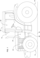
- Figure 1 shows a schematic side view of an agricultural towing vehicle 10 according to the invention, in particular in the form of a tractor.
- the basic structure of an agricultural towing vehicle 10 is assumed to be known to the person skilled in the art.
- the towing vehicle 10 has two or more ground engagement means, in particular in the form of wheels 14, 16, which engage with a ground for transmitting driving forces and/or by means of which the towing vehicle 10 is supported on the ground 18.
- the ground engagement means can be arranged or suspended on a front axle and a rear axle.
- the ground engagement means are front wheels 14, which can be arranged on the front axle. and/or rear wheels 16 which can be arranged on the rear axle.
- the towing vehicle 10 can also have a chassis, the chassis being supported in particular by the ground engagement means suspended on the front axle and the rear axle.
- the towing vehicle 10 has a drive 22, which is shown in outline, for example a motor, which can be designed in the form of an internal combustion engine.
- the towing vehicle 10 can comprise a transmission device 24, in particular a transmission.
- the ground engagement means can be driven or are driven by the drive 22, in particular by the drive 22 which interacts with the transmission device 24.
- an output torque of the transmission device 24 can be transmitted to the ground engagement means via a drive train.
- the towing vehicle 10 has a cabin 20 in which an operator workstation 26 is arranged.
- the towing vehicle 10 comprises a vehicle braking system 28 according to the invention.
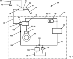
- FIG 2 shows a schematic representation of a first embodiment of the vehicle brake system 28 according to the invention.
- the vehicle braking system 28 shown is a detailed schematic representation of the Figure 1 shown vehicle braking system 28. In the following, therefore, only reference is made to Figure 1 details not shown.
- the vehicle brake system 28 can, as shown in Figure 1 shown, be installed in an agricultural tractor 10.
- the vehicle brake system 28 has a first brake circuit 30, in particular a first hydraulic brake circuit.
- the first brake circuit 30 is provided between a pump 40 and a first wheel cylinder 32, in particular a first hydraulic wheel cylinder.
- the pump 40 can be operated in the first brake circuit 30 to generate pressure and to move a fluid, preferably hydraulic fluid, particularly preferably hydraulic oil, within the first brake circuit 30.
- the first wheel cylinder 32 can be designed such that one or more front and/or rear Wheels 14, 16 can be braked or are braked with the first wheel cylinder 32.
- the first brake circuit 30 is coupled, in particular by means of the first wheel cylinder 32, to one or more rear wheels 16.
- the first brake circuit 30, in particular the first wheel cylinder 32 can also be coupled to only one or more front wheels 14.
- the vehicle brake system 28 comprises a first master cylinder 34 with a first master cylinder connection 36 and a first actuating device 50 with a first actuating connection 52.
- the first master cylinder connection 36 and the first actuating connection 52 are respectively the inlet and outlet for the flowing fluid.
- the vehicle brake system 28 comprises a first actuating line 38 which connects the first master cylinder connection 36 and the first actuating connection 52.
- the first master cylinder 34 is thus in flow connection or flow-connected to the first actuating device 50.
- the first actuating device 50 can be operated with the first master cylinder 34 or is operated with it, preferably adjustable and/or adjustable, particularly preferably actuated.
- the first master cylinder 34 can exert a force on the first actuating device 50, for example by actuating the first master cylinder 34 with a brake pedal 54, in particular by exerting a flow and/or a pressure of the fluid from the first master cylinder 34 to the first actuating device 50.
- a first valve device 60 is provided, in particular arranged, in the first brake circuit 30.
- the first valve device 60 is movable between a first configuration in which a flow connection between the pump 40 and the first wheel cylinder 32 is established, in particular by means of the first valve device 60, and a second configuration in which a flow connection between the pump 40 and the first wheel cylinder 32 is prevented, in particular by means of the first valve device 60.
- the first valve device 60 in particular when the first Actuating device 50 is actuated with the first master cylinder 34, operable with the first actuating device 50 or operable in such a way, preferably adjustable and/or adjustable, particularly preferably actuated or actuated in such a way that the first valve device 60 is or is moved into the first configuration.
- the first valve device 60 is operable, preferably adjustable and/or adjustable, particularly preferably actuable, in order to establish a flow connection between the pump 40 and the first wheel cylinder 32 in a first configuration and to prevent a flow connection between the pump 40 and the first wheel cylinder 32 in a second configuration.
- the first valve device 60 in particular when the first actuating device 50 is actuated with the first master cylinder 34, is operable with the first actuating device 50 or is operable, preferably adjustable and/or adjustable, particularly preferably actuable or actuable in such a way that the first valve device 60 is or is movable into the first configuration, in particular from the second configuration into the first configuration.
- the first actuating device 50 can be designed to exert a switching force S on the first valve device 60.
- the first actuating device 50 and the first valve device 60 can be designed and operable in such a way that, in particular when the first actuating device 50 is actuated with the first master cylinder 34, the first actuating device 50 actuates the first valve device 60 with the switching force S, so that the first valve device 60 can be or is moved into the first configuration.
- the first valve device 60 can comprise a first brake valve, in particular be a first brake valve that can be arranged in the first brake circuit 30.
- the first master cylinder 34 comprises a first master cylinder chamber 46 and a first master cylinder piston 44 arranged in the first master cylinder chamber 46.
- the first master cylinder connection 36 can be an inlet and outlet of the first master cylinder chamber 46 of the first master cylinder 34.
- the first master cylinder piston 44 can be brought into a retracted and extended position in relation to the first master cylinder chamber 46 in the first master cylinder chamber 46 by applying pressure.
- the first master cylinder 34 in particular the first master cylinder piston 44, can be actuated by the brake pedal 54, in particular the first master cylinder 34 can be actuated by the brake pedal 54 that can be actuated by a user.
- the first brake circuit 30, in particular the first wheel cylinder 32 is therefore designed to brake a front and/or rear wheel 14, 16, in particular a front and/or rear driven wheel, in response to an actuation of the brake pedal 54. In response to actuation of the brake pedal 54, the first wheel cylinder 32 may brake the front and/or rear wheels 14, 16.
- the first master cylinder 34 includes a first reservoir connection 70.
- the first reservoir connection 70 is the inlet and outlet for the fluid.
- a reservoir 72 is also provided.
- the reservoir 72 can serve as a drain and emergency supply for the first master cylinder 34 and/or a second master cylinder (see Figures 6 and 7 , reference number 140).
- the first reservoir connection 70 is connected to the reservoir 72 by a first reservoir line 74.
- the first master cylinder 34 is thus in flow connection or flow-connected to the reservoir 72.
- the reservoir 72 only has the connection to the first and/or second master cylinder 34, 140, and is therefore an independent reservoir.
- the reservoir 72 is independent of the steering return and in particular is not designed as a component of the steering return.
- the pump 40 is connected to a storage charging device 80 by means of a line 82.
- a first brake line 84 of the first brake circuit 30 connects the storage charging device 80 to the first valve device 60, in particular the first brake valve.
- a further first brake line 86 of the first brake circuit 30 connects the first valve device 60 to the first wheel cylinder 32.
- a first accumulator 90 is arranged on or in the first brake line 84 between the accumulator charging device 80 and the first valve device 60.
- the first accumulator 90 is in flow connection with the first brake line 84 or is flow-connected and/or is arranged downstream of the accumulator charging device 80 in the flow direction.
- the pump 40 is also in flow connection with a fluid container 88 or is flow-connected and/or is arranged downstream of the fluid container 88 in the flow direction.
- the first actuating device 50 can actuate the first valve device 60 with pressure.
- the first actuating device 50 is designed as a first secondary cylinder.
- the first actuating device 50 also comprises a first supply connection 100.
- the first supply connection 100 is the inlet and outlet for the fluid.
- the pump 40 is connected to the first actuating device 50 by means of a first supply line 102.
- the pump 40 is thus in flow connection or flow-connected to the first actuating device 50.
- a pressure relief valve 104 can be arranged, which opens if there is a pressure in the first supply line 102 that exceeds a predetermined maximum pressure.
- a check valve 106 can be arranged in the first supply line 102 between the first supply connection 100 and the pressure relief valve 104.
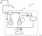
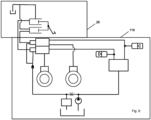
- FIG. 3 shows a schematic representation of a second embodiment of the vehicle brake system 28 according to the invention.
- the vehicle braking system shown essentially corresponds to the one shown in the Figures 1 and 2 vehicle braking system shown, so that only details and/or differences are discussed below.
- the vehicle brake system 28 comprises a second brake circuit 110.
- the second brake circuit 110 is provided, in particular arranged or formed, between the pump 40 and a second wheel cylinder 112.
- the pump 40 can be operated in the second brake circuit 110 to generate pressure and move the fluid within the second brake circuit 110.
- the second brake circuit 110 is coupled, in particular by means of the second wheel cylinder 112, to a single or multiple front wheels 14.
- the second brake circuit 110 can also be coupled to just a single or multiple rear wheels 16.
- the first brake circuit 30 can be coupled to the rear wheels 16 and the second brake circuit 110 to the front wheels 14.
- the first brake circuit 30 can also be coupled to a rear or front wheel 14, 16 and the second brake circuit 110 to another rear or front wheel 14, 16.
- a further second brake line 114 of the second brake circuit 110 connects the first valve device 60 to the second wheel cylinder 112.
- the first and/or second brake circuit 30, 110 can be physically provided in a hydraulic unit 116.
- the first valve device 60 in particular the first brake valve, is provided, in particular arranged, in the first and second brake circuits 30, 110.
- the first valve device 60 is movable between a first configuration in which a flow connection between the pump 40 and the first and second wheel cylinders 32, 112 is established, in particular by means of the first valve device 60, and a second configuration in which a flow connection between the pump 40 and the first and second wheel cylinders 32, 112 is prevented, in particular by means of the first valve device 60.
- the first valve device 60 is operable with the first actuating device 50 or operable in such a way, preferably adjustable and/or adjustable, particularly preferably operable or operable in such a way that the first valve device 60 is or is moved into the first configuration, particularly when the first actuating device 50 is actuated with the first master cylinder 34.
- the second brake circuit 110 in particular the second wheel cylinder 112, is designed to brake a front and/or rear wheel 14, 16, in particular a front and/or rear driven wheel 14, 16, in response to an actuation of the brake pedal 54. In response to an actuation of the brake pedal 54, the second wheel cylinder 112 can therefore brake the front and/or rear wheel 14, 16.
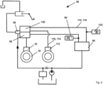
- Figure 4 shows a schematic representation of a third embodiment of the vehicle brake system 28 according to the invention.
- the vehicle braking system 28 shown essentially corresponds to the one shown in the Figures 1 to 3 shown vehicle braking system 28, so that only details and/or differences are discussed below.
- the vehicle braking system 28 comprises Figure 4 a second valve device 120.
- the second valve device 120 can be arranged, in particular as shown, between the pump 40 and the second wheel cylinder 112.
- the second valve device 120 is provided, in particular arranged, in the second brake circuit 110.
- the second valve device 120 is movable between a third configuration in which a flow connection between the pump 40, or in particular the second pump, and the second wheel cylinder 112 is established, in particular by means of the second valve device 120, and a fourth configuration in which a flow connection between the pump 40 and the second wheel cylinder 112 is prevented, in particular by means of the second valve device 120.
- the first and second valve devices 60, 120 in particular when the first actuating device 50 is actuated with the first master cylinder 34, are provided with the first actuating device 50 is operable or operable, preferably adjustable and/or adjustable, particularly preferably actuable or actuable such that the first valve device 60 is or is moved into the first configuration and the second valve device 120 into the third configuration, in particular is or is moved from the fourth configuration into the third configuration.
- the first actuating device 50 can be designed to exert a switching force S on the first and second valve devices 60, 120.
- the first actuating device 50 and the first and second valve devices 60, 120 can be designed and operated in such a way that, in particular when the first actuating device 50 is actuated with the first master cylinder 34, the first actuating device 50 actuates the first and second valve devices 60, 120 with the switching force S, so that the first valve device 60 can be moved into the first configuration and the second valve device 120 into the third configuration.
- the first actuating device 50 can also actuate the first and second valve devices 60, 120 with pressure.
- the first actuating device 50 moves the first valve device 60 into the first configuration and the second valve device 120 into the third configuration.
- the first slave cylinder in particular the first slave cylinder piston, can move the first valve device 60 into the first configuration and the second valve device 120 into the third configuration when the first actuating port 52 is pressurized by the first master cylinder 34.
- a second brake line 118 of the second brake circuit 110 connects the accumulator charging device 80 to the second valve device 120, in particular the second brake valve.
- a further second brake line 118 of the second Brake circuit 110 connects the second valve device 120 to the second wheel cylinder 112.
- a second accumulator 122 is arranged on or in the second brake line 118 between the accumulator charging device 80 and the second valve device 120.
- the second accumulator 122 is in flow connection or flow-connected to the second valve device 120 and the accumulator charging device 80 by means of the second brake line and/or is arranged downstream of the accumulator charging device in the flow direction.
- Figure 5 shows a schematic representation of a fourth embodiment of the vehicle brake system 28 according to the invention.
- the vehicle braking system 28 shown essentially corresponds to the one shown in the Figures 1 to 4 shown vehicle braking system 28, so that only details and/or differences are discussed below.
- the vehicle brake system 28 comprises a second actuating device 130 with a second actuating connection 132.
- the first master cylinder connection 36 is in flow connection with the second actuating connection 132.
- the second actuating device 130 can be operated with the first master cylinder 34 or is operated with it, preferably adjustable and/or adjustable, particularly preferably actuated.
- the first valve device 60 can be operated with the first actuating device 50 and the second valve device 120 can be operated with the second actuating device 130 or can be operated in such a way, preferably adjustable and/or adjustable, particularly preferably actuated or actuated in such a way that the first valve device 60 can be moved into the first configuration and the second valve device 120 can be moved into the third configuration.
- the first master cylinder port 36 and the second actuation port 132 are each have an inlet and outlet for the flowing fluid, in particular the hydraulic fluid.
- the vehicle brake system 28 comprises a second actuation line 134.
- the first master cylinder connection 36 is therefore connected to the second actuation connection 132 by means of the second actuation line 134.
- the first master cylinder 34 is therefore in flow connection with the second actuation device 130 or the first master cylinder 34 is flow-connected to the second actuation device 130.
- the first master cylinder connection 36 is connected to the first and second actuation connections 52, 132.
- the second actuation device 130 can, for example, be designed to exert a switching force S on the second valve device 120.
- the second actuation device 130 can, for example, comprise a second pressure valve, in particular a piston, with the second actuation connection, or can be designed as the pilot valve or second secondary cylinder described.
- the second actuating device 130 also comprises a second supply connection 136.
- the second supply connection 136 is the inlet and outlet for the fluid.
- the pump 40 is connected to the second actuating device 120 by means of a second supply line 138.
- the pump 40 is therefore in flow connection or flow-connected to the second actuating device 120.
- the first and second supply lines 102, 138 run partially as a common line, with the pressure relief valve 104, the check valve 106 and the throttle 108 being arranged in the common line.
- the first and second supply lines 102, 138 can also be designed as completely separate lines.
- a further pressure relief valve 104 can then be arranged in the second supply line 138, which opens if there is a pressure in the second supply line 138 that exceeds a predetermined maximum pressure.
- Figure 6 shows a schematic representation of a fifth embodiment of the vehicle brake system 28 according to the invention.
- the vehicle braking system 28 shown essentially corresponds to the one shown in the Figures 1 to 5 shown vehicle braking system 28, so that only details and/or differences are discussed below.
- the vehicle brake system 28 comprises a second master cylinder 140 with a second master cylinder connection 142.
- the second master cylinder connection 142 and the second actuation connection 132 are respectively the inlet and outlet for the fluid.
- the first master cylinder connection 36 is connected to the first actuation connection 52 by means of the first actuation line 38 and the second master cylinder connection 142 is connected to the second actuation connection 132 by means of the second actuation line 134.
- the second master cylinder 140 is therefore in flow connection with the second actuation device 130 or the second master cylinder 140 is flow-connected to the second actuation device 130.
- the second actuation device 130 can be operated with the second master cylinder 140 or is operated with it, preferably adjustable and/or adjustable, particularly preferably actuated.
- the second valve device 120 in particular when the second actuating device 130 is actuated with the second master cylinder 140, is operable with the second actuating device 130 or operable in such a way, preferably adjustable and/or adjustable, particularly preferably actuable or actuable in such a way that the second valve device 120 is movable or is moved into the third configuration.
- the second master cylinder 140 includes a second master cylinder chamber 146 and a in the second master cylinder piston 144 arranged in the second master cylinder chamber 146.
- the second master cylinder connection 142 can be an inlet and outlet of the second master cylinder chamber 146.
- the second master cylinder piston 144 can be brought into a retracted and extended position relative to the second master cylinder chamber 146 in the second master cylinder chamber 146 by applying pressure.
- the second master cylinder 140 in particular the second master cylinder piston 144, can be actuated with a further brake pedal 150, in particular the second master cylinder 140 can be actuated by the further brake pedal 150 that can be actuated by a user.
- the second master cylinder 140 comprises a second reservoir connection 152.
- the second reservoir connection 152 is the inlet and outlet for the fluid.
- the second reservoir connection 152 is connected to the reservoir 72 by a second reservoir line 154.
- the second master cylinder 140 is thus in flow connection with the reservoir 72.
- Figure 7 shows a schematic representation of a sixth embodiment of the vehicle braking system 28 according to the invention.
- the vehicle braking system 28 shown essentially corresponds to the one shown in the Figures 1 to 6 shown vehicle braking system 28, so that only details and/or differences are discussed below.
- the first and second master cylinders 34, 140 in particular the first and second master cylinder pistons 44, 144, can only be actuated together with the brake pedal 54.
- the vehicle brake system 28 is thus designed to simultaneously brake the front and/or rear wheels 14, 16 assigned to the respective first and second wheel cylinders 32, 112 in response to an actuation of the brake pedal 54.
- the first and second brake circuits 30, 110, in particular the first and second wheel cylinders 32, 112 can thus jointly brake the front and/or rear wheels 14, 16 assigned to the first and second wheel cylinders 32, 112 in response to an actuation of the brake pedal 54.
- the first and/or second master cylinder 34, 140 and the reservoir 72 are arranged in the cabin 20 and all other components of the vehicle brake system 28 are arranged in all other parts of the towing vehicle, in particular on or in the chassis.
- Figure 8 shows a schematic representation of an arrangement of a vehicle brake system 28 according to the invention in a towing vehicle 10 according to the invention.
- the vehicle braking system 28 shown essentially corresponds to the one shown in the Figures 1 to 7 shown vehicle brake system 28 and towing vehicle 10, so that only details and/or differences are discussed below. Only the first and/or second master cylinder and the reservoir, and in particular the associated lines, are arranged in the cabin 20.
- All other components of the vehicle braking system are located on, particularly in, the chassis.
- Figure 9 shows a schematic representation of the first or second actuating device with the respective associated valve device 60.
- the details of the vehicle brake system 28 shown correspond essentially to the Figures 1 to 8 shown vehicle braking system 28 or the towing vehicle 10, so that only details and/or differences are discussed below.
- the first valve device (60) contains a first reset element 180 for resetting to the second configuration.
- the first valve device (60) contains a second reset element (182) for resetting to the second configuration.
- the second valve device 120 can have a first reset element 180 for resetting to the fourth configuration.
- the second valve device 120 can have a second reset element 182 for resetting to the fourth configuration.
- the fluid flow is thereby interrupted upon slight actuation of the brake pedal 54 and/or the further brake pedal 150, with each further movement building up pressure and the first and/or second valve device 60, 120 being actuated.
Landscapes
- Engineering & Computer Science (AREA)
- Physics & Mathematics (AREA)
- Fluid Mechanics (AREA)
- Transportation (AREA)
- Mechanical Engineering (AREA)
- Transmission Of Braking Force In Braking Systems (AREA)
- Regulating Braking Force (AREA)
Description
- Die Erfindung betrifft eine Fahrzeugbremsanlage gemäss dem Oberbegriff des unabhängigen Anspruchs 1 und ein landwirtschaftliches Zugfahrzeug gemäss dem Oberbegriff des unabhängigen Anspruchs 14.
- Bekannte Fahrzeugbremsanlagen in landwirtschaftlichen Zugfahrzeugen umfassen Ventilanordnungen zum Bremsen, insbesondere mit einer ersten und/oder zweiten Ventileinrichtung bzw. Ventilen, die insbesondere in einer Kabine des Zugfahrzeugs angeordnet sind. Aufgrund dieser Anordnung der Ventilanordnungen weist die Fahrzeugbremsanlage eine komplexe Führung der Leitungen und Anschlüsse auf, d.h. die Hydraulikversorgung und die Radzylinder zum Bremsen eines Rades können an einem Fahrgestell angeordnet und ein Grossteil der Ventilanordnung in der Kabine. Nachteile der bekannten Ventilanordnung sind somit, dass diese einen grossen Einbauraum in der Kabine, insbesondere am Bremspedal, benötigen und hydraulische Störgeräusche in die Kabine übertragen. Das der Erfindung zu Grunde liegende Problem wird somit darin gesehen eine Fahrzeugbremsanlage und ein landwirtschaftliches Zugfahrzeug bereitzustellen, die bekannten Fahrzeugbremsanlagen und landwirtschaftlichen Zugfahrzeug optimieren. Die
DE 10 2018 111 451 A1 offenbart eine Bremseinrichtung einer mobilen Arbeitsmaschine mit mindestens zwei Bremskreisen einer Betriebsbremse. - Ausgehend von diesem Stand der Technik ist es daher eine Aufgabe der vorliegenden Erfindung eine Fahrzeugbremsanlage und ein landwirtschaftliches Zugfahrzeug vorzuschlagen, welche die aus dem Stand der Technik bekannten Nachteile weitgehend vermeidet, insbesondere eine Fahrzeugbremsanlage und ein landwirtschaftliches Zugfahrzeug vorzuschlagen, die konstruktiv einfacher ausgestaltet sind, beispielsweise temperaturunabhängig und/oder wartungsfrei sind, und/oder weniger Einbauraum benötigen und/oder Störgeräusche verringern und/oder vermeiden.
- Diese Aufgabe wird durch eine Fahrzeugbremsanlage mit den Merkmalen des Anspruchs 1 und ein und ein landwirtschaftliches Zugfahrzeug mit den Merkmalen des Anspruchs 14 gelöst.
- Die abhängigen Ansprüche beziehen sich auf besonders vorteilhafte Ausführungsformen der Erfindung.
- Erfindungsgemäß wird eine Fahrzeugbremsanlage vorgeschlagen. Die Fahrzeugbremsanlage umfasst einen ersten Hauptzylinder mit einem ersten Hauptzylinderanschluss und eine erste Betätigungseinrichtung mit einem ersten Betätigungsanschluss. Der erste Hauptzylinderanschluss ist in Strömungsverbindung mit dem ersten Betätigungsanschluss, diese sind also insbesondere strömungsverbunden, und die erste Betätigungseinrichtung ist mit dem ersten Hauptzylinder betreibbar, bevorzugt derart einstellbar und/oder verstellbar, besonders bevorzugt betätigbar. Die Fahrzeugbremsanlage umfasst weiter einen ersten Bremskreis, insbesondere einen hydraulischen Bremskreis, der zwischen einer Pumpe und einem ersten Radzylinder, insbesondere einem ersten hydraulischen Radzylinder, vorgesehen ist, insbesondere angeordnet ist. Die Pumpe ist dabei im ersten Bremskreis betreibbar, insbesondere auch angeordnet, um Druck zu erzeugen und ein Fluid, insbesondere Hydraulikflüssigkeit oder Hydrauliköl, innerhalb des ersten Bremskreises zu bewegen. Im ersten Bremskreis ist ausserdem eine erste Ventileinrichtung vorgesehen, insbesondere angeordnet. Die erste Ventileinrichtung ist zwischen einer ersten Konfiguration, also insbesondere eine erste Schaltstellung, in der eine Strömungsverbindung zwischen der Pumpe und dem ersten Radzylinder hergestellt ist, insbesondere mittels der ersten Ventileinrichtung hergestellt ist, und einer zweiten Konfiguration, insbesondere einer zweiten Schaltstellung, beweglich, in der eine Strömungsverbindung zwischen der Pumpe und dem ersten Radzylinder verhindert ist, insbesondere mittels der ersten Ventileinrichtung verhindert ist. Darüber hinaus ist die erste Ventileinrichtung, insbesondere wenn die erste Betätigungseinrichtung mit dem ersten Hauptzylinder betätigt wird, mit der ersten Betätigungseinrichtung betreibbar oder derart betreibbar, bevorzugt einstellbar und/oder verstellbar, besonders bevorzugt betätigbar oder derart betätigbar, dass die erste Ventileinrichtung in die erste Konfiguration bewegbar ist oder bewegt wird.
- Mit anderen Worten, die erste Ventileinrichtung ist betreibbar, um in einer ersten Konfiguration eine Strömungsverbindung zwischen der Pumpe und dem ersten Radzylinder herzustellen und in einer zweiten Konfiguration eine Strömungsverbindung zwischen der Pumpe und dem ersten Radzylinder zu verhindern. Dabei ist die die erste Ventileinrichtung, insbesondere wenn die erste Betätigungseinrichtung mit dem ersten Hauptzylinder betätigt wird, mit der ersten Betätigungseinrichtung betreibbar oder derart betreibbar, bevorzugt einstellbar und/oder verstellbar, besonders bevorzugt betätigbar oder derart betätigbar, dass die erste Ventileinrichtung in die erste Konfiguration, insbesondere von der zweiten Konfiguration in die erste Konfiguration bewegbar ist oder bewegt wird.
- Der erste Hauptzylinderanschluss und der erste Betätigungsanschluss können jeweils Einlass und Auslass für das Fluid sein. Ausserdem steht der erste Hauptzylinderanschluss, beispielsweise mittels einer ersten Betätigungsleitung, in Verbindung mit dem ersten Betätigungsanschluss. Der erste Hauptzylinder ist also mit der ersten Betätigungseinrichtung in Strömungsverbindung bzw. der erste Hauptzylinder ist mit der ersten Betätigungseinrichtung strömungsverbunden. Der erste Hauptzylinder kann eine erste Hauptzylinderkammer und einen in der ersten Hauptzylinderkammer angeordneten ersten Hauptzylinderkolben umfassen. Dabei kann der erste Hauptzylinderanschluss ein Einlass und Auslass der ersten Hauptzylinderkammer des ersten Hauptzylinders sein. Der erste Hauptzylinderkolben ist in der ersten Hauptzylinderkammer durch Beaufschlagung mit Druck in eine bezogen auf die erste Hauptzylinderkammer eingefahrene und ausgefahrene Stellung bringbar. Der erste Hauptzylinder, insbesondere der erste Hauptzylinderkolben, kann durch ein betätigbares Bremspedal, das insbesondere in der Kabine eines landwirtschaftlichen Zugfahrzeugs angeordnet sein kann, betätigt werden. Der erste Hauptzylinder kann also durch das von einem Benutzer betätigbare Bremspedal betätigt werden.
- Die Fahrzeugbremsanlage weist einen ersten Bremskreis auf. Der erste Radzylinder kann derart ausgestaltet sein, dass eines oder mehrere vordere und/oder hintere Räder, insbesondere angetriebene Räder, mit dem ersten Radzylinder bremsbar ist bzw. gebremst wird. Der erste Bremskreis, insbesondere der erste Radzylinder, kann an das eine oder mehrere hintere Räder und/oder an das eine oder mehrere vorderen Räder gekoppelt sein. Der erste Bremskreis, insbesondere der erste Radzylinder, ist ausgestaltet, als Reaktion auf eine Betätigung des Bremspedals eines oder mehrere vordere und/oder hintere Räder, insbesondere angetriebene Räder, zu bremsen. Als Reaktion auf eine Betätigung des Bremspedals kann der erste Radzylinder eines oder mehrere vordere und/oder hintere Räder bremsen.
- Der erste Bremskreis kann physikalisch in einem Hydraulikaggregat bereitgestellt werden. Die Fahrzeugbremsanlage kann das Hydraulikaggregat umfassen. Das Hydraulikaggregat kann so konfiguriert sein, dass es für eine Bremskraftverteilung und/oder Antriebssteuerung als Teil eines allgemeinen elektronischen Stabilitätsprogramms (ESP) des Zugfahrzeugs sorgt, da bereits viele derselben Ausstattungskomponenten von der Fahrzeugbremsanlage bereitgestellt werden können. Die Fahrzeugbremsanlage kann eine Brems-Antiblockierfunktionalität aufweisen, um beim scharfen Bremsen oder Bremsen auf reibungsarmen Oberflächen ein Blockieren der Räder und ein Schleudern zu verhindern. Obwohl das Hydraulikaggregat in Fahrzeugbremsanlagen mit Antiblockier- und sonstigen Funktionen eingesetzt werden kann, ist seine Anwendung nicht auf solche Systeme begrenzt.
- Die erste Ventileinrichtung kann ein erstes Bremsventil umfassen, insbesondere ein erstes Bremsventil sein, das nur im ersten Bremskreis oder im ersten und einem zweiten Bremskreis angeordnet sein kann. Die erste Ventileinrichtung, insbesondere das erste Bremsventil, kann standardmäßig die zweite Konfiguration einnehmen. Die erste Ventileinrichtung, insbesondere das erste Bremsventil, und/oder eine zweite Ventileinrichtung, insbesondere ein zweites Bremsventil können beispielsweise als ein betätigbares 4/2 oder 5/2 oder 4/3 oder 5/3 Wegeventil mit vier oder fünf Anschlüsse ausgeführt sein. Die erste Ventileinrichtung, insbesondere das erste Bremsventil, können zumindest die erste und zweite Konfiguration umfassen, wobei die erste Konfiguration eine Durchflussstellung ist und die zweite Konfiguration eine Sperrstellung ist.
- Die erste Betätigungseinrichtung kann zur Ausübung einer Schaltkraft S auf die erste Ventileinrichtung ausgebildet sein. Die erste Betätigungseinrichtung kann die erste Ventileinrichtung mit Druck betätigen. Die erste Betätigungseinrichtung kann beispielsweise ein erstes Druckventil, beispielsweise ein Kolben, mit dem ersten Betätigungsanschluss umfassen, wobei, wenn der erste Betätigungsanschluss vom ersten Hauptzylinder mit eine Kraft, insbesondere mit Druck, beaufschlagt wird, das erste Druckventil die erste Ventileinrichtung in die erste Konfiguration bewegt, insbesondere die erste Ventileinrichtung mit dem ersten Druckventil von der zweiten Konfiguration in die erste Konfiguration bewegbar ist oder bewegt wird. Die ersten Betätigungseinrichtung und die erste Ventileinrichtung können derart ausgestaltet und betreibbar sein, dass, insbesondere wenn die erste Betätigungseinrichtung mit dem ersten Hauptzylinder betätigt wird, die erste Betätigungseinrichtung die erste Ventileinrichtung mit der Schaltkraft S betätigt, sodass die erste Ventileinrichtung in die erste Konfiguration bewegbar ist oder bewegt wird. Die erste Betätigungseinrichtung kann auch als ein integraler Bestandteil der ersten Ventileinrichtung, insbesondere des ersten Bremsventils, ausgebildet sein. Die erste Betätigungseinrichtung ist als ein erster Nebenzylinder ausgebildet. Der erste Nebenzylinder umfasst eine erste Nebenzylinderkammer und einen in der ersten Nebenzylinderkammer angeordneten ersten Nebenzylinderkolben. Dabei ist der erste Betätigungsanschluss ein Einlass und Auslass der ersten Nebenzylinderkammer des ersten Nebenzylinders.
- Der erste Nebenzylinderkolben kann in der ersten Nebenzylinderkammer durch Beaufschlagung mit Druck in eine bezogen auf die erste Nebenzylinderkammer eingefahrene und ausgefahrene Stellung bringbar sein. Der erste Nebenzylinder, insbesondere der erste Nebenzylinderkolben, kann, wenn der erste Betätigungsanschluss vom ersten Hauptzylinder mit Druck beaufschlagt wird, die erste Ventileinrichtung in die erste Konfiguration bewegen, insbesondere die erste Ventileinrichtung von der zweiten Konfiguration in die erste Konfiguration bewegen.
- Die Pumpe kann mittels einer Leitung mit einer Speicherladeeinrichtung, insbesondere einem Speicherladeventil verbunden, insbesondere in Strömungsverbindung oder strömungsverbunden sein. Die Pumpe kann auch als eine erste und zweite Pumpe ausgebildet sein. Der erste Bremskreises kann, beispielsweise mittels einer ersten Bremsleitung, die Speicherladeeinrichtung mit der ersten Ventileinrichtung, insbesondere dem ersten Bremsventil verbinden. Darüber hinaus kann der erste Bremskreis, insbesondere mittels einer weiteren ersten Bremsleitung, die erste Ventileinrichtung mit dem ersten Radzylinder verbinden. Zwischen der Speicherladeeinrichtung und der ersten Ventileinrichtung kann an oder in der ersten Bremsleitung ein erster Speicher, bevorzugt ein erster Behälter, besonders bevorzugt ein erster Druckspeicher angeordnet sein. Der erste Druckspeicher kann eine Blase umfassen. Der erste Speicher oder erste Behälter können mit der ersten Bremsleitung in Strömungsverbindung bzw. strömungsverbunden und/oder der Speicherladeeinrichtung in Strömungsrichtung nachgeordnet sein. Die Pumpe kann ausserdem mit einem Fluidbehälter in Strömungsverbindung bzw. strömungsverbunden und/oder dem Fluidbehälter in Strömungsrichtung nachgeordnet sein. Die Pumpe kann eine Druckquelle, insbesondere eine Hydraulikpumpe sein. Der erste Bremskreis kann also von der Pumpe bis zum erste Radzylinder ausgebildet sein. Im Weiteren kann der erste Bremskreis die erste Bremsleitung, die weitere erste Bremsleitung, die erste Ventileinrichtung, den ersten Radzylinder und die erste Betätigungseinrichtung umfassen.
- Wesentlich für die Erfindung ist, dass die erste Ventileinrichtung, insbesondere wenn die erste Betätigungseinrichtung mit dem ersten Hauptzylinder betätigt wird, mit der ersten Betätigungseinrichtung betreibbar ist, dass die erste Ventileinrichtung in die erste Konfiguration bewegbar ist oder bewegt wird. Dadurch kann eine Fahrzeugbremsanlage mit einem geschlossenen Haupt-Neben-System, hier erster Hauptzylinder und erste Betätigungseinrichtung, insbesondere und/oder ein zweiter Hauptzylinder und/oder mit einer zweiten Betätigungseinrichtung, realisiert werden, wobei der erste und/oder zweite Hauptzylinder vorteilhafterweise wesentlich kleiner ausgeführt und insbesondere direkt mit dem Bremspedal verbunden sein können. Weiterer Vorteil ist, dass die Fahrzeugbremsanlage, insbesondere das Fluid, keine Einschränkungen im Modulationsverhalten und der Ansprechzeit bei niedriger Umgebungstemperatur aufweist. Die Erfindung ermöglicht somit vorteilhafterweise eine hochdynamische und/oder temperaturunabhängige und/oder wartungsfreie Fahrzeugbremsanlage, insbesondere mit minimalem Einbauraum um das Bremspedal und/oder reduziertem Leitungsführungsaufwand zur Kabine (geringere Anzahl von Leitungen und kleinerer Querschnitt) und/oder Geräuschreduzierung. Darüber hinaus kann die Fahrzeugbremsanlage unabhängig vom Lenkungsrücklauf betrieben werden und ist insbesondere nicht mit dem Lenkungsrücklaufs verbunden. Im Weiteren kann mittels der Fahrzeugbremsanlage vorteilhafterweise ein kleiner kontinuierlicher Fluidstrom und/oder Fluiddruck, bevorzugt der Hydraulikflüssigkeit, besonders bevorzugt des Hydrauliköls, realisiert werden, wodurch auf eine Überwachung des Fluids verzichtet werden kann.
- In Ausgestaltung der Erfindung umfasst die Fahrzeugbremsanlage einen zweiten Bremskreis, insbesondere einen zweite hydraulischen Bremskreis, der zwischen der Pumpe und einem zweiten Radzylinder, insbesondere einem zweiten hydraulischen Radzylinder vorgesehen ist, insbesondere angeordnet ist. Die Pumpe ist im zweiten Bremskreis betreibbar, insbesondere betreibbar und angeordnet, um Druck zu erzeugen und das Fluid innerhalb des zweiten Bremskreises zu bewegen. Der zweite Radzylinder kann derart ausgestaltet sein, dass eines oder mehrere vordere und/oder hintere Räder, insbesondere angetriebene Räder, mit dem zweiten Radzylinder bremsbar ist bzw. gebremst wird. Der zweite Bremskreis, insbesondere der zweite Radzylinder, kann an das eine oder mehrere hintere Räder und/oder an das eine oder mehrere vorderen Räder gekoppelt sein. Der zweite Bremskreis, insbesondere der zweite Radzylinder, ist ausgestaltet, als Reaktion auf eine Betätigung des Bremspedals eines oder mehrere vordere und/oder hintere Räder, insbesondere angetriebene Räder, zu bremsen. Als Reaktion auf eine Betätigung des Bremspedals kann der zweite Radzylinder eines oder mehrere vordere und/oder hintere Räder bremsen. Im Speziellen kann der erste Bremskreis, insbesondere der erste Radzylinder, an die hinteren Räder und der zweite Bremskreis, insbesondere der zweite Radzylinder, an die vorderen Räder gekoppelt sein. Ebenso kann aber auch der erste Bremskreis an eines oder mehrere hintere oder vordere Räder und der zweite Bremskreis an eines oder mehrere weitere hintere oder weitere vordere Räder gekoppelt sein. Der erste und zweite Bremskreise können insbesondere in Kreise für jeweils eines oder mehrere hintere Räder und/oder jeweils eines oder mehrere vordere Räder unterteilt sein. Der erste und/oder zweite Bremskreis können physikalisch im Hydraulikaggregat bereitgestellt werden. Der zweite Bremskreis, insbesondere der zweite Radzylinder, kann ausgestaltet sein, als Reaktion auf eine Betätigung des Bremspedals ein vorderes und/oder hinteres Rad, insbesondere ein vorderes und/oder hinteres angetriebenes Rad, zu bremsen. Als Reaktion auf eine Betätigung des Bremspedals kann der zweite Radzylinder also das vordere und/oder hintere Rad bremsen. Falls die Pumpe als eine erste und zweite Pumpe ausgebildet ist, kann der erste Bremskreis zwischen der ersten Pumpe und dem ersten Radzylinder ausgebildet sein, insbesondere angeordnet sein, und der zweite Bremskreis kann zwischen der zweiten Pumpe und dem zweiten Radzylinder ausgebildet sein, insbesondere angeordnet sein. Die erste Pumpe kann somit im ersten Bremskreis betreibbar sein, um Druck zu erzeugen und Fluid, insbesondere Hydraulikflüssigkeit, innerhalb des ersten Bremskreises zu bewegen, und die zweite Pumpe im zweiten Bremskreis betreibbar sein, um Druck zu erzeugen und Fluid innerhalb des zweiten Bremskreises zu bewegen. Vorteilhafterweise ermöglichen ein erster und zweiter Bremskreis eine unterschiedliche Abbremsung und/oder eine redundante Fahrzeugbremsanlage.
- In Ausgestaltung der Erfindung ist im ersten und zweiten Bremskreis die erste Ventileinrichtung, insbesondere das erste Bremsventil, vorgesehen, insbesondere angeordnet. Die erste Ventileinrichtung ist zwischen einer ersten Konfiguration, in der eine Strömungsverbindung zwischen der Pumpe und dem ersten und zweiten Radzylinder hergestellt ist, insbesondere mittels der ersten Ventileinrichtung hergestellt ist, und einer zweiten Konfiguration beweglich, in der eine Strömungsverbindung zwischen der Pumpe und dem ersten und zweiten Radzylinder verhindert ist, insbesondere mittels der ersten Ventileinrichtung verhindert ist. Die erste Ventileinrichtung ist, insbesondere wenn die erste Betätigungseinrichtung mit dem ersten Hauptzylinder betätigt wird, mit der ersten Betätigungseinrichtung betreibbar oder derart betreibbar, bevorzugt einstellbar und/oder verstellbar, besonders bevorzugt betätigbar oder derart betätigbar, dass die erste Ventileinrichtung in die erste Konfiguration bewegbar ist oder bewegt wird. Die erste Ventileinrichtung kann aber auch nur im ersten Bremskreis angeordnet sein. Vorteilhafterweise können somit der erste und zweite Bremskreis auf einfache Art und Weise nur mit der ersten Ventileinrichtung betrieben werden.
- In Ausgestaltung der Erfindung ist im zweiten Bremskreis eine zweite Ventileinrichtung vorgesehen, insbesondere angeordnet. Die zweite Ventileinrichtung kann dabei insbesondere zwischen der Pumpe und dem zweiten Radzylinder und der Pumpe angeordnet sein. Die im zweiten Bremskreis angeordnete zweite Ventileinrichtung ist zwischen einer dritten Konfiguration, in der eine Strömungsverbindung zwischen der Pumpe und dem zweiten Radzylinder hergestellt ist, insbesondere mittels der zweiten Ventileinrichtung hergestellt ist, und einer vierten Konfiguration beweglich, in der eine Strömungsverbindung zwischen der Pumpe und dem zweiten Radzylinder verhindert ist, insbesondere mittels der zweiten Ventileinrichtung verhindert ist. Die zweite Ventileinrichtung kann ein zweites Bremsventil umfassen, insbesondere ein zweites Bremsventil sein, das im zweiten Bremskreis angeordnet sein kann. Die zweite Ventileinrichtung, insbesondere das zweite Bremsventil, kann standardmäßig die vierte Konfiguration einnehmen. Die zweite Ventileinrichtung, insbesondere das zweite Bremsventil, können beispielsweise als ein betätigbares 4/2 oder 5/2 oder 4/3 oder 5/3 Wegeventil mit vier oder fünf Anschlüsse ausgeführt sein. Die zweite Ventileinrichtung, insbesondere das zweite Bremsventil, können zumindest die dritte und vierte Konfiguration (Schaltstellung) umfassen, wobei die dritte Konfiguration eine Durchflussstellung ist und die vierte Konfiguration eine Sperrstellung ist. Die zweite Ventileinrichtung kann genau wie die erste Ventileinrichtung ausgestaltet ein, insbesondere können die erste und zweite Ventileinrichtung identisch sein. Der zweite Bremskreis kann, beispielsweise mittels einer zweiten Bremsleitung, die Speicherladeeinrichtung mit der zweiten Ventileinrichtung, insbesondere dem zweiten Bremsventil verbinden. Darüber hinaus kann der zweite Bremskreis, insbesondere mittels einer weiteren zweiten Bremsleitung, die zweite Ventileinrichtung mit dem zweiten Radzylinder verbinden. Zwischen der Speicherladeeinrichtung und der zweiten Ventileinrichtung kann an oder in der zweiten Bremsleitung ein zweiter Speicher, bevorzugt ein zweiter Behälter, besonders bevorzugt ein zweiter Druckspeicher angeordnet sein. Der zweite Druckspeicher kann eine Blase umfassen. Der zweite Speicher oder zweite Behälter können mit der zweiten Bremsleitung in Strömungsverbindung bzw. strömungsverbunden und/oder der Speicherladeeinrichtung in Strömungsrichtung nachgeordnet sein. Im Weiteren kann der zweite Bremskreis die zweite Bremsleitung, die weitere zweite Bremsleitung, die zweite Ventileinrichtung, den zweiten Radzylinder und die zweite Betätigungseinrichtung umfassen. Vorteilhafterweise können dadurch ein erster und zweiter Bremskreis konstruktiv auf einfache Art und Weise ausgebildet werden. Darüber hinaus kann die Fahrzeugbremsanlage redundant betrieben werden.
- In Ausgestaltung der Erfindung ist die erste und zweite Ventileinrichtung, insbesondere wenn die erste Betätigungseinrichtung mit dem ersten Hauptzylinder betätigt wird, mit der ersten Betätigungseinrichtung betreibbar oder derart betreibbar, bevorzugt einstellbar und/oder verstellbar, besonders bevorzugt betätigbar oder derart betätigbar, dass die erste Ventileinrichtung in die erste Konfiguration und die zweite Ventileinrichtung in die dritte Konfiguration bewegbar ist oder bewegt wird, insbesondere von der vierten Konfiguration in die dritte Konfiguration bewegbar ist oder bewegt wird. Dabei kann beispielsweise die erste Betätigungseinrichtung zur Ausübung einer Schaltkraft S auf die erste und zweite Ventileinrichtung ausgebildet sein. Die ersten Betätigungseinrichtung und die erste und zweite Ventileinrichtung können dabei derart ausgestaltet und betreibbar sein, dass, insbesondere wenn die erste Betätigungseinrichtung mit dem ersten Hauptzylinder betätigt wird, die erste Betätigungseinrichtung die erste und zweite Ventileinrichtung mit der Schaltkraft S betätigt, sodass die erste Ventileinrichtung in die erste Konfiguration und die zweite Ventileinrichtung in die dritte Konfiguration bewegbar sind oder bewegt werden. Die erste Betätigungseinrichtung kann auch als ein integraler Bestandteil der ersten und zweiten Ventileinrichtung, insbesondere des ersten und zweiten Bremsventils, ausgebildet sein. Die erste Betätigungseinrichtung kann die erste und zweite Ventileinrichtung mit Druck betätigen. Wenn der erste Betätigungsanschluss vom ersten Hauptzylinder mit Druck beaufschlagt wird, bewegt das erste Druckventil die erste Ventileinrichtung in die erste Konfiguration und die zweite Ventileinrichtung in die dritte Konfiguration. Im Speziellen kann der erste Nebenzylinder, insbesondere der erste Nebenzylinderkolben, wenn der erste Betätigungsanschluss vom ersten Hauptzylinder mit Druck beaufschlagt wird, die erste Ventileinrichtung in die erste Konfiguration und die zweite Ventileinrichtung in die dritte Konfiguration bewegen. Vorteilhafterweise können dadurch ein erster und zweiter Bremskreis auf einfache Art und Weise betrieben werden. Ausserdem kann dadurch die Fahrzeugbremsanlage konstruktiv einfacher ausgestaltet werden und benötigt weniger Einbauraum im Zugfahrzeug, insbesondere der Kabine. Darüber hinaus werden Störgeräusche reduziert oder vermieden.
- In Ausgestaltung der Erfindung umfasst die Fahrzeugbremsanlage eine zweite Betätigungseinrichtung mit einem zweiten Betätigungsanschluss, wobei der erste Hauptzylinderanschluss in Strömungsverbindung mit dem zweiten Betätigungsanschluss ist, insbesondere also strömungsverbunden ist. Die zweite Betätigungseinrichtung ist mit dem ersten Hauptzylinder betreibbar, bevorzugt einstellbar und/oder verstellbar, besonders bevorzugt betätigbar. Die erste Ventileinrichtung ist mit der ersten Betätigungseinrichtung betreibbar und die zweite Ventileinrichtung ist mit der zweiten Betätigungseinrichtung betreibbar oder derart betreibbar, bevorzugt einstellbar und/oder verstellbar, besonders bevorzugt betätigbar oder derart betätigbar, insbesondere wenn die erste und zweite Betätigungseinrichtung mit dem ersten Hauptzylinder betätigt werden, dass die erste Ventileinrichtung in die erste Konfiguration und die zweite Ventileinrichtung in die dritte Konfiguration bewegbar sind oder bewegt werden. Die zweite Betätigungseinrichtung kann zur Ausübung einer Schaltkraft S auf die zweite Ventileinrichtung ausgebildet sein. Die zweite Betätigungseinrichtung kann die zweite Ventileinrichtung mit Druck betätigen. Die zweite Betätigungseinrichtung kann beispielsweise ein zweites Druckventil, beispielsweise ein Kolben, mit dem zweiten Betätigungsanschluss umfassen, wobei, wenn der zweite Betätigungsanschluss vom ersten Hauptzylinder mit Druck beaufschlagt wird, das zweite Druckventil die zweite Ventileinrichtung in die dritte Konfiguration bewegt, insbesondere die zweite Ventileinrichtung mit dem zweiten Druckventil von der vierten Konfiguration in die dritte Konfiguration bewegbar ist oder bewegt wird. Die zweiten Betätigungseinrichtung und die zweite Ventileinrichtung können dabei derart ausgestaltet und betreibbar sein, dass, insbesondere wenn die zweite Betätigungseinrichtung mit dem ersten Hauptzylinder betätigt wird, die zweite Betätigungseinrichtung die zweite Ventileinrichtung mit der Schaltkraft S betätigt, sodass die zweite Ventileinrichtung in die dritte Konfiguration bewegbar ist oder bewegt wird. Die zweite Betätigungseinrichtung kann auch als ein integraler Bestandteil der zweiten Ventileinrichtung, insbesondere des zweiten Bremsventils, ausgebildet sein. Die zweite Betätigungseinrichtung kann aber auch als ein Vorsteuerventil (z. B. einem elektromagnetisch gesteuerten, im Ruhezustand offenen Zweistellungsventil), oder ein zweiter Nebenzylinder ausgebildet sein. Der zweite Nebenzylinder kann eine zweite Nebenzylinderkammer und einen in der zweiten Nebenzylinderkammer angeordneten zweiten Nebenzylinderkolben umfassen. Dabei kann der zweite Betätigungsanschluss ein Einlass und Auslass der zweiten Nebenzylinderkammer des zweiten Nebenzylinders sein. Der zweite Nebenzylinderkolben kann in der zweiten Nebenzylinderkammer durch Beaufschlagung mit Druck in eine bezogen auf die zweite Nebenzylinderkammer eingefahrene und ausgefahrene Stellung bringbar sein. Der zweite Nebenzylinder, insbesondere der zweite Nebenzylinderkolben, kann, wenn der zweite Betätigungsanschluss vom ersten Hauptzylinder mit Druck beaufschlagt wird, die zweite Ventileinrichtung in die dritte Konfiguration bewegen, insbesondere die zweite Ventileinrichtung von der vierten Konfiguration in die dritte Konfiguration bewegen. Der erste Hauptzylinder kann aber auch einen weiteren ersten Hauptzylinderanschluss aufweisen. Der weitere erste Hauptzylinderanschluss und der zweite Betätigungsanschluss können jeweils Einlass und Auslass für das strömende Fluid sein. Der weitere erste Hauptzylinderanschluss kann also, anstatt des ersten Hauptzylinderanschlusses, mittels der zweiten Betätigungsleitung mit dem zweiten Betätigungsanschluss verbunden sein. Der erste Hauptzylinder kann also mit der zweiten Betätigungseinrichtung in Strömungsverbindung stehen bzw. der erste Hauptzylinder mit der zweiten Betätigungseinrichtung strömungsverbunden sein. In diesem Ausführungsbeispiel kann der erste Hauptzylinderanschluss mit dem ersten Betätigungsanschluss und der weitere erste Hauptzylinderanschluss mit dem zweiten Betätigungsanschluss verbunden sein. Vorteilhafterweise können dadurch der erste und zweite Bremskreis auf einfache Art und Weise redundant betrieben werden. Ausserdem kann dadurch die Fahrzeugbremsanlage konstruktiv einfacher ausgestaltet werden.
- In Ausgestaltung der Erfindung umfasst die Fahrzeugbremsanlage einen zweiten Hauptzylinder mit einem zweiten Hauptzylinderanschluss und die zweite Betätigungseinrichtung mit einem zweiten Betätigungsanschluss, wobei der zweite Hauptzylinderanschluss in Strömungsverbindung mit dem zweiten Betätigungsanschluss ist und die zweite Betätigungseinrichtung mit dem zweiten Hauptzylinder betreibbar ist, bevorzugt einstellbar und/oder verstellbar, besonders bevorzugt betätigbar ist. Die erste Ventileinrichtung ist, insbesondere wenn die erste Betätigungseinrichtung mit dem ersten Hauptzylinder betätigt wird, mit der ersten Betätigungseinrichtung betreibbar oder derart betreibbar, bevorzugt einstellbar und/oder verstellbar, besonders bevorzugt betätigbar oder derart betätigbar, dass die erste Ventileinrichtung, insbesondere mittels der ersten Betätigungseinrichtung, in die erste Konfiguration bewegbar ist oder bewegt wird, und/oder die zweite Ventileinrichtung ist, insbesondere wenn der zweite Betätigungseinrichtung mit dem zweiten Hauptzylinder betätigt wird, mit der zweiten Betätigungseinrichtung betreibbar oder derart betreibbar, bevorzugt einstellbar und/oder verstellbar, besonders bevorzugt betätigbar oder derart betätigbar, dass die zweite Ventileinrichtung, insbesondere mittels der zweiten Betätigungseinrichtung, in die dritte Konfiguration bewegbar ist oder bewegt wird. Mit anderen Worten, die zweite Ventileinrichtung ist, insbesondere wenn die zweite Betätigungseinrichtung mit dem zweiten Hauptzylinder betätigt wird, mit der zweiten Betätigungseinrichtung betreibbar, dass die zweite Ventileinrichtung in die dritte Konfiguration, insbesondere von der vierten Konfiguration in die dritte Konfiguration bewegbar ist oder bewegt wird. Im Speziellen können die zweite Betätigungseinrichtung und die zweite Ventileinrichtung dabei derart ausgestaltet und betreibbar sein, dass die zweite Betätigungseinrichtung die zweite Ventileinrichtung mit der Schaltkraft S betätigt, sodass die zweite Ventileinrichtung in die dritte Konfiguration bewegbar ist oder bewegt wird. Der zweite Hauptzylinderanschluss kann jeweils Einlass und Auslass für das Fluid sein. Der zweite Hauptzylinder kann also mit der zweiten Betätigungseinrichtung in Strömungsverbindung stehen bzw. der zweite Hauptzylinder mit der zweiten Betätigungseinrichtung strömungsverbunden sein, beispielsweise mittels einer zweiten Betätigungsleitung. Die zweite Betätigungseinrichtung, insbesondere das zweite Druckventil, kann, wenn der zweite Betätigungsanschluss vom zweiten Hauptzylinder mit einer Kraft, insbesondere Druck beaufschlagt wird, die zweite Ventileinrichtung in die dritte Konfiguration bewegen. Falls die zweite Betätigungseinrichtung als zweiter Nebenzylinder ausgebildet ist, kann der zweite Nebenzylinder, insbesondere der zweite Nebenzylinderkolben, wenn der zweite Betätigungsanschluss vom zweiten Hauptzylinder mit Druck beaufschlagt wird, die zweite Ventileinrichtung in die dritte Konfiguration bewegen. Der zweite Hauptzylinder kann eine zweite Hauptzylinderkammer und einen in der zweiten Hauptzylinderkammer angeordneten zweiten Hauptzylinderkolben umfassen. Dabei kann der zweite Hauptzylinderanschluss ein Einlass und Auslass der zweiten Hauptzylinderkammer sein. Der zweite Hauptzylinderkolben kann in der zweiten Hauptzylinderkammer durch Beaufschlagung mit Druck in eine bezogen auf die zweite Hauptzylinderkammer eingefahrene und ausgefahrene Stellung bringbar sein. Der erste und zweite Hauptzylinder, insbesondere der erste und zweite Hauptzylinderkolben, können durch das Bremspedal betätigt werden, insbesondere können der erste und zweite Hauptzylinder durch das von einem Benutzer betätigbare Bremspedal betätigt werden. Der erste und zweite Bremskreis, insbesondere der erste und zweite Radzylinder sind also ausgestaltet, als Reaktion auf eine Betätigung des Bremspedals jeweils eines oder mehrere vordere und/oder hintere Räder, insbesondere ein vorderes und/oder hinteres angetriebenes Rad, zu bremsen. Es kann aber auch sein, dass der erste Hauptzylinder mit dem Bremspedal und der zweite Hauptzylinder, insbesondere der zweite Hauptzylinderkolben, mit einem weiteren Bremspedal betätigt wird, insbesondere kann der zweite Hauptzylinder durch das von einem Benutzer betätigbare weitere Bremspedal betätigt werden. Der zweite Bremskreis, insbesondere der zweite Radzylinder, kann also ausgestaltet sein, als Reaktion auf eine Betätigung des weiteren Bremspedals eines oder mehrere vordere und/oder hintere Räder zu bremsen. Dadurch können alle oben genannten Vorteile der erfindungsgemässen Fahrzeugbremsanlage realisiert werden.
- In Ausgestaltung der Erfindung weist die erste Betätigungseinrichtung einen ersten Versorgungsanschluss und/oder die zweite Betätigungseinrichtung einen zweiten Versorgungsanschluss auf. Darüber hinaus können der erste und/oder zweite Versorgungsanschluss mittels einer ersten Versorgungsleitung mit der Pumpe strömungsverbunden sein, d.h. entweder ist nur der erste Versorgungsanschluss mittels der ersten Versorgungsleitung mit der Pumpe strömungsverbunden oder der erste und zweite Versorgungsanschluss sind mittels der ersten Versorgungsleitung gleichzeitig mit der Pumpe strömungsverbunden. Ebenso kann aber auch der erste Versorgungsanschluss mittels einer ersten Versorgungsleitung mit der Pumpe, insbesondere der ersten Pumpe, strömungsverbunden sein und/oder der zweite Versorgungsanschluss mittels einer zweiten Versorgungsleitung mit der Pumpe, insbesondere der zweiten Pumpe, strömungsverbunden sein. Der erste Versorgungsanschluss ist Einlass und Auslass für das Fluid. Der zweite Versorgungsanschluss kann Einlass und Auslass für das Fluid sein.
- Im Speziellen ist der erste Versorgungsanschluss ein Einlass und Auslass der ersten Nebenzylinderkammer des ersten Nebenzylinders. Der zweite Versorgungsanschluss kann ein Einlass und Auslass der zweiten Nebenzylinderkammer des zweiten Nebenzylinders sein. Die Pumpe kann mittels der ersten und/oder zweiten Versorgungsleitung mit der ersten und/oder zweite Betätigungseinrichtung verbunden sein, also mit der ersten und/oder zweite Betätigungseinrichtung in Strömungsverbindung stehen bzw. strömungsverbunden sein. In der ersten Versorgungsleitung kann ein erstes Überdruckventil und/oder in der zweiten Versorgungsleitung ein zweites Überdruckventil angeordnet sein, das bzw. die sich öffnen, sollte in der jeweiligen Versorgungsleitung ein Druck anstehen, der einen vorgegebenen Höchstdruck übersteigt. Ebenso kann in der ersten und/oder zweiten Versorgungsleitung zwischen dem ersten und/oder dem zweiten Versorgungsanschluss und dem jeweiligen zugeordneten Überdruckventil jeweils ein Rückschlagventil angeordnet sein, insbesondere ein erstes Rückschlagventil in der ersten Versorgungsleitung und/oder ein zweites Rückschlagventil in der zweiten Versorgungsleitung angeordnet sein. Um den Druck in der ersten und/oder zweiten Versorgungsleitung zu senken, kann zwischen der Pumpe und dem jeweiligen Überdruckventil in der ersten Versorgungsleitung eine erste Drossel bzw. ein Drosselventil und/oder in der zweiten Versorgungsleitung eine zweite Drossel bzw. ein Drosselventil angeordnet sein. Vorteilhafterweise kann dadurch ein kleiner kontinuierlicher Fluidstrom und/oder Fluiddruck des Fluids zur ersten und/oder zweiten Betätigungseinrichtung realisiert werden. Darüber hinaus kann von Vorteil die Größe eines Reservoirs erheblich reduziert werden.
- In Ausgestaltung der Erfindung umfasst der erste Hauptzylinder einen ersten Reservoiranschluss und/oder der zweite Hauptzylinder einen zweiten Reservoiranschluss, und/oder der erste Hauptzylinder ist mittels des ersten Reservoiranschlusses und/oder der zweite Hauptzylinder ist mittels des zweiten Reservoiranschlusses mit einem Reservoir strömungsverbunden. Der erste und/oder zweite Reservoiranschluss können Einlass und Auslass für das Fluid sein. Das Reservoir kann als Ablauf und zur Versorgung für den ersten Hauptzylinder und/oder den zweiten Hauptzylinder dienen. Der erste Reservoiranschluss kann mit einer ersten Reservoirleitung und/oder der zweite Reservoiranschluss kann mit einer zweiten Reservoirleitung mit dem Reservoir verbunden sein. Der erste und/oder zweite Hauptzylinder kann also mit dem Reservoir in Strömungsverbindung stehen bzw. strömungsverbunden sein. Vorteilhafterweise weist das Reservoir nur die Verbindung zum ersten und/oder zweiten Hauptzylinder auf, ist also ein unabhängiges Reservoir. Darüber hinaus ist das Reservoir unabhängig vom Lenkungsrücklauf und ist insbesondere nicht als Bestandteil des Lenkungsrücklaufs ausgebildet. Vorteilhafterweise kann dadurch ein kleiner kontinuierlicher Fluidstrom und/oder Fluiddruck des Fluids vom ersten und/oder zweiten Betätigungselement zum ersten und/oder zweiten Hauptzylinder realisiert werden, wodurch auf eine Überwachung des Reservoirs und einen Zugang zum Reservoir zum Nachfüllen verzichtet werden kann. Darüber hinaus kann von Vorteil auf ein geschlossenes Reservoir, also eine Anbindung an vorhandene Reservoirs, beispielsweise Lenkung, verzichtet werden und die Größe des Reservoirs kann erheblich reduziert werden.
- In Ausgestaltung der Erfindung weisen die erste und/oder die zweite Ventileinrichtung jeweils ein erstes Rückstellelement zur Rückstellung in die zweite und/oder vierte Konfiguration auf. Darüber hinaus weist die erste und -optionaldie zweite Ventileinrichtung jeweils ein zweites Rückstellelement zur Rückstellung in die zweite und/oder vierte Konfiguration auf. Das erste und/oder zweite Rückstellelement an der ersten Ventileinrichtung kann also die erste Ventileinrichtung aus der ersten in die zweite Konfiguration bewegen. Ebenso kann das weitere erste und/oder das weitere zweite Rückstellelement an der zweiten Ventileinrichtung die zweite Ventileinrichtung aus der dritten in die vierte Konfiguration bewegen. Das erste und/oder zweite Rückstellelement können z.B. mechanisch oder elektromechanisch oder elektromagnetisch gesteuert sein. Das erste und/oder zweite Rückstellelement können beispielsweise als Feder oder als eine elektrische Betätigung mit magnetischer Spule ausgebildet sein. Das zweite Rückstellelement ist vorteilhafterweise eine zusätzliche Betätigung zur Kompensation des Stromes und/oder Drucks des Fluids in der ersten und/oder zweiten Ventileinrichtung. Von Vorteil kann mittels des ersten und zweiten Rückstellelements die Rückstellung des ersten und/oder zweiten Ventileinrichtung genauer gesteuert werden. Vorteilhafterweise kann dadurch auch bei leichter Betätigung des Bremspedals und/oder des weiteren Bremspedals der Fluidstrom unterbrochen werden, wobei jede weitere Bewegung Druck aufbaut und die erste und/oder zweite Ventileinrichtung betätigt.
- Die Erfindung betrifft weiter ein landwirtschaftliches Zugfahrzeug, umfassend eine Fahrzeugbremsanlage nach einem der Ansprüche 1 bis 13. Das erfindungsgemässe landwirtschaftliche Zugfahrzeug weist die oben beschriebenen Vorteile der erfindungsgemässen Fahrzeugbremsanlage auf. In Ausgestaltung der Erfindung umfasst das landwirtschaftliches Zugfahrzeug eine Kabine und ein Fahrgestell, wobei die Kabine am, insbesondere auf, dem Fahrgestell angeordnet ist. Darüber hinaus sind, insbesondere nur, der erste und/oder zweite Hauptzylinder und das Reservoir, sowie insbesondere die zugehörigen Leitungen, in der Kabine angeordnet. Alle anderen Bestandteile der Fahrzeugbremsanlage können am, insbesondere im, Fahrgestell angeordnet sein.
- Die erfindungsgemässe Fahrzeugbremsanlage und/oder das Zugfahrzeug können eine Steuereinheit umfassen. Die Steuereinheit und/oder weitere Steuereinheit (engl. ECU = electronic control unit oder ECM = electronic control module) kann ein elektronisches Modul und/oder ein eingebettetes System sein. Die Steuereinheit kann ein Speichermodul und/oder einen Prozessor umfassen. Die Steuereinheit kann mit dem ersten und/oder zweiten Hauptzylinder, der ersten und/oder zweiten Betätigungseinrichtung, insbesondere Nebenzylinder, der ersten und/oder zweiten Ventileinrichtung, einem oder mehreren Sensoren und/oder dem Speicher und/oder Prozessor und/oder dem Hydraulikaggregat signalverbunden sein, also datenleitend verbunden sein. Die Verbindung kann kabelgebunden oder kabellos, also per Funk, realisiert sein. Der Kommunikationsbus kann beispielsweise Isobus, CAN-Bus oder ähnliches sein kann. Die Steuereinheit kann als Teil der Fahrzeugbremsanlage oder am Zugfahrzeug vorgesehen sein. Im Speziellen können auch zwei Steuereinheiten, eine erste für das Zugfahrzeug und eine zweite für die Fahrzeugbremsanlage vorgesehen sein. Ausserdem können der erste und/oder zweite Hauptzylinder und/oder die erste und/oder zweite Betätigungseinrichtung, insbesondere der Nebenzylinder, und/oder die erste und/oder zweite Ventileinrichtung und/oder der eine oder mehrere Sensoren mittels der Steuereinheit verstellbar und/oder einstellbar sein. Der oder die Sensoren können Eingangsinformationen liefern, in der Regel in Bezug auf relative Raddrehzahlen, sodass die Steuereinheit den Betrieb des Hydraulikaggregats regeln kann.
- Im Folgenden werden die Erfindung sowie weitere Vorteile und vorteilhafte Weiterbildungen und Ausgestaltungen der Erfindung sowohl in apparativer als auch in verfahrenstechnischer Hinsicht anhand von Ausführungsbeispielen und unter Bezugnahme auf die Zeichnung näher erläutert. Dabei sind hinsichtlich ihrer Funktion übereinstimmende bzw. vergleichbare Bauteile mit denselben Bezugszeichen gekennzeichnet. In den schematischen Zeichnungen zeigen:
- Fig. 1
- eine schematische Darstellung eines erfindungsgemässen landwirtschaftlichen Zugfahrzeugs, und
- Fig. 2
- eine schematische Darstellung eines ersten Ausführungsbeispiels der erfindungsgemässen Fahrzeugbremsanlage, und
- Fig. 3
- eine schematische Darstellung eines zweiten Ausführungsbeispiels der erfindungsgemässen Fahrzeugbremsanlage, und
- Fig. 4
- eine schematische Darstellung eines dritten Ausführungsbeispiels der erfindungsgemässen Fahrzeugbremsanlage, und
- Fig. 5
- eine schematische Darstellung eines vierten Ausführungsbeispiels der erfindungsgemässen Fahrzeugbremsanlage, und
- Fig. 6
- eine schematische Darstellung eines fünften Ausführungsbeispiels der erfindungsgemässen Fahrzeugbremsanlage, und
- Fig. 7
- eine schematische Darstellung eines sechsten Ausführungsbeispiels der erfindungsgemässen Fahrzeugbremsanlage, und
- Fig. 8
- eine schematische Darstellung einer Anordnung einer erfindungsgemässen Fahrzeugbremsanlage in einem erfindungsgemässen Zugfahrzeug.
- Fig. 9
- eine schematische Darstellung einer Anordnung einer erfindungsgemässen Fahrzeugbremsanlage in einem erfindungsgemässen Zugfahrzeug.
-
Figur 1 zeigt eine schematische Seitenansicht eines erfindungsgemässen landwirtschaftlichen Zugfahrzeugs 10, insbesondere in Form eines Ackerschleppers oder Traktors. Der grundsätzliche Aufbau eines landwirtschaftlichen Zugfahrzeugs 10 wird als dem Fachmann bekannt angenommen. - Das Zugfahrzeug 10 weist zwei oder mehrere Bodeneingriffsmittel auf, insbesondere in Form von Rädern 14, 16, welche mit einem Untergrund zur Übertragung von Antriebskräften in Eingriff stehen und/oder durch die sich das Zugfahrzeug 10 auf dem Untergrund 18 abstützt. Die Bodeneingriffsmittel können an einer Vorderachse und einer Hinterachse angeordnet oder aufgehängt sein. Im Speziellen sind die Bodeneingriffsmittel vordere Räder 14, die an der Vorderachse angeordnet sein können, und/oder hintere Räder 16, die an der Hinterachse angeordnet sein können. Das Zugfahrzeug 10 kann ausserdem ein Fahrgestell aufweisen, wobei das Fahrgestell insbesondere von den an der Vorderachse und der Hinterachse aufgehängten Bodeneingriffsmitteln getragen wird.
- Darüber hinaus weist das Zugfahrzeug 10 einen andeutungsweise gezeigten Antrieb 22 auf, beispielsweise einen Motor, welcher in Form eines Verbrennungsmotors ausgebildet sein kann. Ausserdem kann das Zugfahrzeug 10 eine Getriebeeinrichtung 24, insbesondere ein Getriebe umfassen. Die Bodeneingriffsmittel sind mit dem Antrieb 22, insbesondere mit dem Antrieb 22 der mit der Getriebeeinrichtung 24 zusammenwirkt, antreibbar oder werden angetrieben. Dabei kann insbesondere ein Ausgangsdrehmoment der Getriebeeinrichtung 24 über einen Antriebsstrang auf die Bodeneingriffsmittel übertragen werden. Das Zugfahrzeug 10 verfügt über eine Kabine 20, in der ein Bedienerarbeitsplatz 26 angeordnet ist. Ausserdem umfasst das Zugfahrzeug 10 eine erfindungsgemässe Fahrzeugbremsanlage 28.
-
Figur 2 zeigt eine schematische Darstellung eines ersten Ausführungsbeispiels der erfindungsgemässen Fahrzeugbremsanlage 28. Die inFigur 2 gezeigte Fahrzeugbremsanlage 28 ist eine detaillierte schematische Darstellung der inFigur 1 gezeigten Fahrzeugbremsanlage 28. Im Folgenden wird deshalb lediglich auf inFigur 1 nicht gezeigte Details eingegangen. Die Fahrzeugbremsanlage 28 kann, wie inFigur 1 dargestellt, in ein landwirtschaftliches Zugfahrzeug 10 eingebaut sein. - Die Fahrzeugbremsanlage 28 weist einen ersten Bremskreis 30, insbesondere einen ersten hydraulischen Bremskreis auf. Der erste Bremskreis 30 ist zwischen einer Pumpe 40 und einem ersten Radzylinder 32, insbesondere einem ersten hydraulischen Radzylinder, vorgesehen. Die Pumpe 40 ist im ersten Bremskreis 30 betreibbar, um Druck zu erzeugen und ein Fluid, bevorzugt Hydraulikflüssigkeit, besonders bevorzugt Hydrauliköl, innerhalb des ersten Bremskreises 30 zu bewegen. Der erste Radzylinder 32 kann derart ausgestaltet sein, dass eines oder mehrere vordere und/oder hintere Räder 14, 16 mit dem ersten Radzylinder 32 bremsbar ist bzw. gebremst wird. In
Figur 2 ist der erste Bremskreis 30, insbesondere mittels des ersten Radzylinders 32, an das eine oder mehrere hintere Räder 16 gekoppelt. Der erste Bremskreis 30, insbesondere der erste Radzylinder 32, kann aber auch nur eines oder mehrere vordere Räder 14 gekoppelt sein. - Wie in
Fig. 2 gezeigt, umfasst die Fahrzeugbremsanlage 28, einen ersten Hauptzylinder 34 mit einem ersten Hauptzylinderanschluss 36 und eine erste Betätigungseinrichtung 50 mit einem ersten Betätigungsanschluss 52. Der erste Hauptzylinderanschluss 36 und der erste Betätigungsanschluss 52 sind jeweils Einlass und Auslass für das strömende Fluid. Die Fahrzeugbremsanlage 28 umfasst eine erste Betätigungsleitung 38, die den ersten Hauptzylinderanschluss 36 und den ersten Betätigungsanschluss 52 verbindet. Der erste Hauptzylinder 34 ist also mit der ersten Betätigungseinrichtung 50 in Strömungsverbindung oder strömungsverbunden. Darüber hinaus ist die erste Betätigungseinrichtung 50 mit dem ersten Hauptzylinder 34 betreibbar oder wird mit diesem betrieben, bevorzugt einstellbar und/oder verstellbar, besonders bevorzugt betätigbar. Dabei kann der erste Hauptzylinder 34 eine Kraft auf die erste Betätigungseinrichtung 50 ausüben, beispielsweise indem der erste Hauptzylinder 34 mit einem Bremspedal 54 betätigt wird, insbesondere indem ein Strom und/oder ein Druck des Fluids vom ersten Hauptzylinder 34 zur ersten Betätigungseinrichtung 50 ausgeübt wird. - Im Weiteren ist im ersten Bremskreis 30 eine erste Ventileinrichtung 60 vorgesehen, insbesondere angeordnet. Die erste Ventileinrichtung 60 ist zwischen einer ersten Konfiguration, in der eine Strömungsverbindung zwischen der Pumpe 40 und dem ersten Radzylinder 32 hergestellt ist, insbesondere mittels der ersten Ventileinrichtung 60 hergestellt ist, und einer zweiten Konfiguration beweglich, in der eine Strömungsverbindung zwischen der Pumpe 40 und dem ersten Radzylinder 32 verhindert ist, insbesondere mittels der ersten Ventileinrichtung 60 verhindert ist. Ausserdem ist die die erste Ventileinrichtung 60, insbesondere wenn die erste Betätigungseinrichtung 50 mit dem ersten Hauptzylinder 34 betätigt wird, mit der ersten Betätigungseinrichtung 50 betreibbar oder derart betreibbar, bevorzugt einstellbar und/oder verstellbar, besonders bevorzugt betätigbar oder derart betätigbar, dass die erste Ventileinrichtung 60 in die erste Konfiguration bewegbar ist oder bewegt wird.
- Mit anderen Worten, die erste Ventileinrichtung 60 ist betreibbar, bevorzugt derart einstellbar und/oder verstellbar, besonders bevorzugt betätigbar, um in einer ersten Konfiguration eine Strömungsverbindung zwischen der Pumpe 40 und dem ersten Radzylinder 32 herzustellen und in einer zweiten Konfiguration eine Strömungsverbindung zwischen der Pumpe 40 und dem ersten Radzylinder 32 zu verhindern. Dabei ist die die erste Ventileinrichtung 60, insbesondere wenn die erste Betätigungseinrichtung 50 mit dem ersten Hauptzylinder 34 betätigt wird, mit der ersten Betätigungseinrichtung 50 betreibbar oder derart betreibbar, bevorzugt einstellbar und/oder verstellbar, besonders bevorzugt betätigbar oder derart betätigbar, dass die erste Ventileinrichtung 60 in die erste Konfiguration, insbesondere von der zweiten Konfiguration in die erste Konfiguration bewegbar ist oder bewegt wird.
- Dabei kann beispielsweise die erste Betätigungseinrichtung 50 zur Ausübung einer Schaltkraft S auf die erste Ventileinrichtung 60 ausgebildet sein. Die ersten Betätigungseinrichtung 50 und die erste Ventileinrichtung 60 können dabei derart ausgestaltet und betreibbar sein, dass, insbesondere wenn die erste Betätigungseinrichtung 50 mit dem ersten Hauptzylinder 34 betätigt wird, die erste Betätigungseinrichtung 50 die erste Ventileinrichtung 60 mit der Schaltkraft S betätigt, sodass die erste Ventileinrichtung 60 in die erste Konfiguration bewegbar ist oder bewegt wird. Die erste Ventileinrichtung 60 kann ein erstes Bremsventil umfassen, insbesondere ein erstes Bremsventil sein, das im ersten Bremskreis 30 angeordnet sein kann.
- Der erste Hauptzylinder 34 umfasst eine erste Hauptzylinderkammer 46 und einen in der ersten Hauptzylinderkammer 46 angeordneten ersten Hauptzylinderkolben 44.
- Dabei kann der erste Hauptzylinderanschluss 36 ein Einlass und Auslass der ersten Hauptzylinderkammer 46 des ersten Hauptzylinders 34 sein. Der erste Hauptzylinderkolben 44 ist in der ersten Hauptzylinderkammer 46 durch Beaufschlagung mit Druck in eine bezogen auf die erste Hauptzylinderkammer 46 eingefahrene und ausgefahrene Stellung bringbar. Der erste Hauptzylinder 34, insbesondere der erste Hauptzylinderkolben 44, kann durch das Bremspedal 54 betätigt werden, insbesondere kann der erste Hauptzylinder 34 durch das von einem Benutzer betätigbare Bremspedal 54 betätigt werden. Der erste Bremskreis 30, insbesondere der erste Radzylinder 32 ist also ausgestaltet, als Reaktion auf eine Betätigung des Bremspedals 54 ein vorderes und/oder hinteres Rad 14, 16, insbesondere ein vorderes und/oder hinteres angetriebenes Rad, zu bremsen. Als Reaktion auf eine Betätigung des Bremspedals 54 kann der erste Radzylinder 32 das vordere und/oder hintere Rad 14, 16 bremsen.
- Der erste Hauptzylinder 34 umfasst einen ersten Reservoiranschluss 70. Der erste Reservoiranschluss 70 ist Einlass und Auslass für das Fluid. Ausserdem ist ein Reservoir 72 vorgesehen. Das Reservoir 72 kann als Ablauf und Notversorgung für den ersten Hauptzylinder 34 und/oder einen zweiten Hauptzylinder (siehe
Figuren 6 und7 , Bezugszeichen 140) vorgesehen sein. Der erste Reservoiranschluss 70 ist mit einer ersten Reservoirleitung 74 mit dem Reservoir 72 verbunden. Der erste Hauptzylinder 34 ist also mit dem Reservoir 72 in Strömungsverbindung bzw. strömungsverbunden. Das Reservoir 72 weist nur die Verbindung zum ersten und/oder zweiten Hauptzylinder 34, 140 auf, ist also ein unabhängiges Reservoir. Darüber hinaus ist das Reservoir 72 unabhängig vom Lenkungsrücklauf und ist insbesondere nicht als Bestandteil des Lenkungsrücklaufs ausgebildet. - Die Pumpe 40 ist mittels einer Leitung 82 mit einer Speicherladeeinrichtung 80 verbunden. Eine erste Bremsleitung 84 des ersten Bremskreises 30 verbindet die Speicherladeeinrichtung 80 mit der ersten Ventileinrichtung 60, insbesondere dem ersten Bremsventil. Eine weitere erste Bremsleitung 86 des ersten Bremskreises 30 verbindet die erste Ventileinrichtung 60 mit dem ersten Radzylinder 32. Zwischen der Speicherladeeinrichtung 80 und der ersten Ventileinrichtung 60 ist an oder in der ersten Bremsleitung 84 ein erster Speicher 90 angeordnet. Der erste Speicher 90 ist mit der ersten Bremsleitung 84 in Strömungsverbindung bzw. strömungsverbunden und/oder der Speicherladeeinrichtung 80 in Strömungsrichtung nachgeordnet. Die Pumpe 40 ist ausserdem mit einem Fluidbehälter 88 in Strömungsverbindung bzw. strömungsverbunden und/oder ist dem Fluidbehälter 88 in Strömungsrichtung nachgeordnet.
- Die erste Betätigungseinrichtung 50 kann die erste Ventileinrichtung 60 mit Druck betätigen. Die erste Betätigungseinrichtung 50 ist als ein erster Nebenzylinder ausgebildet.
- Die erste Betätigungseinrichtung 50 umfasst ausserdem einen ersten Versorgungsanschluss 100. Der erste Versorgungsanschluss 100 ist Einlass und Auslass für das Fluid. Die Pumpe 40 ist mittels einer ersten Versorgungsleitung 102 mit der ersten Betätigungseinrichtung 50 verbunden. Die Pumpe 40 ist also mit der ersten Betätigungseinrichtung 50 in Strömungsverbindung bzw. strömungsverbunden. In der ersten Versorgungsleitung 102 kann, wie in
Figur 2 gezeigt, ein Überdruckventil 104 angeordnet sein, das sich öffnet, sollte in der ersten Versorgungsleitung 102 ein Druck anstehen, der einen vorgegebenen Höchstdruck übersteigt. Ebenso kann in der ersten Versorgungsleitung 102 zwischen dem ersten Versorgungsanschluss 100 und dem Überdruckventil 104 ein Rückschlagventil 106 angeordnet sein. Um den Druck in der ersten Versorgungsleitung 102 zu senken, kann zwischen der Pumpe 40 und dem Überdruckventil 104 eine Drossel 108, insbesondere ein Drosselventil angeordnet sein.Figur 3 zeigt eine schematische Darstellung eines zweiten Ausführungsbeispiels der erfindungsgemässen Fahrzeugbremsanlage 28. Die inFigur 3 gezeigte Fahrzeugbremsanlage entspricht im Wesentlichen der in denFiguren 1 und2 gezeigten Fahrzeugbremsanlage, sodass im Folgenden lediglich auf Details und/oder Unterschiede eingegangen wird. - Die Fahrzeugbremsanlage 28 umfasst einen zweiten Bremskreis 110. Der zweite Bremskreis 110 ist zwischen der Pumpe 40 und einem zweiten Radzylinder 112 vorgesehen, insbesondere angeordnet oder ausgebildet. Die Pumpe 40 ist im zweiten Bremskreis 110 betreibbar, um Druck zu erzeugen und das Fluid innerhalb des zweiten Bremskreises 110 zu bewegen.
- In
Figur 3 ist der zweite Bremskreis 110, insbesondere mittels des zweiten Radzylinders 112, an ein einzelnes oder mehrere vordere Räder 14 gekoppelt. Der zweite Bremskreis 110 kann aber auch nur an ein einzelnes oder mehrere hintere Räder 16 gekoppelt sein. Im Speziellen kann der erste Bremskreis 30 an die hinteren Räder 16 und der zweite Bremskreis 110 an die vorderen Räder 14 gekoppelt sein. Ebenso kann der erste Bremskreis 30 aber auch an ein hinteres oder vorderes Rad 14, 16 und der zweite Bremskreis 110 an ein anderes hinteres oder vorderes Rad 14, 16 gekoppelt sein. Eine weitere zweite Bremsleitung 114 des zweiten Bremskreises 110 verbindet die erste Ventileinrichtung 60 mit dem zweiten Radzylinder 112. Der erste und/oder zweite Bremskreis 30, 110 können physikalisch in einem Hydraulikaggregat 116 bereitgestellt werden. - Die erste Ventileinrichtung 60, insbesondere das erste Bremsventil, ist im ersten und zweiten Bremskreis 30, 110 vorgesehen, insbesondere angeordnet. Die erste Ventileinrichtung 60 ist zwischen einer ersten Konfiguration, in der eine Strömungsverbindung zwischen der Pumpe 40 und dem ersten und zweiten Radzylinder 32, 112 hergestellt ist, insbesondere mittels der ersten Ventileinrichtung 60 hergestellt ist, und einer zweiten Konfiguration beweglich, in der eine Strömungsverbindung zwischen der Pumpe 40 und dem ersten und zweiten Radzylinder 32, 112 verhindert ist, insbesondere mittels der ersten Ventileinrichtung 60 verhindert ist.
- Die erste Ventileinrichtung 60 ist, insbesondere wenn die erste Betätigungseinrichtung 50 mit dem ersten Hauptzylinder 34 betätigt wird, mit der ersten Betätigungseinrichtung 50 betreibbar oder derart betreibbar, bevorzugt einstellbar und/oder verstellbar, besonders bevorzugt betätigbar oder derart betätigbar, dass die erste Ventileinrichtung 60 in die erste Konfiguration bewegbar ist oder bewegt wird. Der zweite Bremskreis 110, insbesondere der zweite Radzylinder 112 ist ausgestaltet, als Reaktion auf eine Betätigung des Bremspedals 54 ein vorderes und/oder hinteres Rad 14,16 zu bremsen, insbesondere ein vorderes und/oder hinteres angetriebenes Rad 14,16. Als Reaktion auf eine Betätigung des Bremspedals 54 kann der zweite Radzylinder 112 also das vordere und/oder hintere Rad 14, 16 bremsen.
-
Figur 4 zeigt eine schematische Darstellung eines dritten Ausführungsbeispiels der erfindungsgemässen Fahrzeugbremsanlage 28. Die inFigur 4 gezeigte Fahrzeugbremsanlage 28 entspricht im Wesentlichen der in denFiguren 1 bis 3 gezeigten Fahrzeugbremsanlage 28, sodass im Folgenden lediglich auf Details und/oder Unterschiede eingegangen wird. - Die Fahrzeugbremsanlage 28 umfasst gemäss
Figur 4 eine zweite Ventileinrichtung 120. Die zweite Ventileinrichtung 120 kann dabei insbesondere wie dargestellt zwischen der Pumpe 40 und dem zweiten Radzylinder 112 angeordnet sein. Die zweite Ventileinrichtung 120 ist im zweiten Bremskreis 110 vorgesehen, insbesondere angeordnet. Die zweite Ventileinrichtung 120 ist zwischen einer dritten Konfiguration, in der eine Strömungsverbindung zwischen der Pumpe 40, oder insbesondere der zweiten Pumpe, und dem zweiten Radzylinder 112 hergestellt ist, insbesondere mittels der zweiten Ventileinrichtung 120 hergestellt ist, und einer vierten Konfiguration beweglich ist, in der eine Strömungsverbindung zwischen der Pumpe 40 und dem zweiten Radzylinder 112 verhindert ist, insbesondere mittels der zweiten Ventileinrichtung 120 verhindert ist. Die erste und zweite Ventileinrichtung 60, 120, insbesondere wenn die erste Betätigungseinrichtung 50 mit dem ersten Hauptzylinder 34 betätigt wird, sind mit der ersten Betätigungseinrichtung 50 betreibbar oder derart betreibbar, bevorzugt einstellbar und/oder verstellbar, besonders bevorzugt betätigbar oder derart betätigbar, dass die erste Ventileinrichtung 60 in die erste Konfiguration und die zweite Ventileinrichtung 120 in die dritte Konfiguration bewegbar ist oder bewegt wird, insbesondere von der vierten Konfiguration in die dritte Konfiguration bewegbar ist oder bewegt wird. - Dabei kann beispielsweise die erste Betätigungseinrichtung 50 zur Ausübung einer Schaltkraft S auf die erste und zweite Ventileinrichtung 60, 120 ausgebildet sein. Die ersten Betätigungseinrichtung 50 und die erste und zweite Ventileinrichtung 60, 120 können dabei derart ausgestaltet und betreibbar sein, dass, insbesondere wenn die erste Betätigungseinrichtung 50 mit dem ersten Hauptzylinder 34 betätigt wird, die erste Betätigungseinrichtung 50 die erste und zweite Ventileinrichtung 60, 120 mit der Schaltkraft S betätigt, sodass die erste Ventileinrichtung 60 in die erste Konfiguration und die zweite Ventileinrichtung 120 in die dritte Konfiguration bewegbar sind oder bewegt werden.
- Die erste Betätigungseinrichtung 50 kann die erste und zweite Ventileinrichtung 60, 120 aber auch mit Druck betätigen. Wenn der erste Betätigungsanschluss 52 vom ersten Hauptzylinder 34 mit Druck beaufschlagt wird, bewegt die erste Betätigungseinrichtung 50 die erste Ventileinrichtung 60 in die erste Konfiguration und die zweite Ventileinrichtung 120 in die dritte Konfiguration. Im Speziellen kann der erste Nebenzylinder, insbesondere der erste Nebenzylinderkolben, wenn der erste Betätigungsanschluss 52 vom ersten Hauptzylinder 34 mit Druck beaufschlagt wird, die erste Ventileinrichtung 60 in die erste Konfiguration und die zweite Ventileinrichtung 120 in die dritte Konfiguration bewegen.
- Darüber hinaus verbindet eine zweite Bremsleitung 118 des zweiten Bremskreises 110 die Speicherladeeinrichtung 80 mit der zweiten Ventileinrichtung 120, insbesondere dem zweiten Bremsventil. Eine weitere zweite Bremsleitung 118 des zweiten Bremskreises 110 verbindet die zweite Ventileinrichtung 120 mit dem zweiten Radzylinder 112. Zwischen der Speicherladeeinrichtung 80 und der zweiten Ventileinrichtung 120 ist an oder in der zweiten Bremsleitung 118 ein zweiter Speicher 122 angeordnet. Der zweite Speicher 122 ist mittels der zweiten Bremsleitung mit der zweiten Ventileinrichtung 120 und der Speicherladeeinrichtung 80 in Strömungsverbindung bzw. strömungsverbunden und/oder der Speicherladeeinrichtung in Strömungsrichtung nachgeordnet.
-
Figur 5 zeigt eine schematische Darstellung eines vierten Ausführungsbeispiels der erfindungsgemässen Fahrzeugbremsanlage 28. Die inFigur 5 gezeigte Fahrzeugbremsanlage 28 entspricht im Wesentlichen der in denFiguren 1 bis 4 gezeigten Fahrzeugbremsanlage 28, sodass im Folgenden lediglich auf Details und/oder Unterschiede eingegangen wird. - Wie in
Figur 5 dargestellt, umfasst die Fahrzeugbremsanlage 28 eine zweite Betätigungseinrichtung 130 mit einem zweiten Betätigungsanschluss 132. Der erste Hauptzylinderanschluss 36 ist dabei in Strömungsverbindung mit dem zweiten Betätigungsanschluss 132. Darüber hinaus ist die zweite Betätigungseinrichtung 130 mit dem ersten Hauptzylinder 34 betreibbar oder wird mit diesem betrieben, bevorzugt einstellbar und/oder verstellbar, besonders bevorzugt betätigbar. Darüber hinaus sind, insbesondere wenn die erste und zweite Betätigungseinrichtung 50, 130 mit dem ersten Hauptzylinder 34 betätigt werden, die erste Ventileinrichtung 60 mit der ersten Betätigungseinrichtung 50 und die zweite Ventileinrichtung 120 mit der zweiten Betätigungseinrichtung 130 betreibbar oder derart betreibbar, bevorzugt einstellbar und/oder verstellbar, besonders bevorzugt betätigbar oder derart betätigbar, dass die erste Ventileinrichtung 60 in die erste Konfiguration und die zweite Ventileinrichtung 120 in die dritte Konfiguration bewegbar sind oder bewegt werden. - Der erste Hauptzylinderanschluss 36 und der zweite Betätigungsanschluss 132 sind jeweils Einlass und Auslass für das strömende Fluid, insbesondere die Hydraulikflüssigkeit. Die Fahrzeugbremsanlage 28 umfasst eine zweite Betätigungsleitung 134. Der erste Hauptzylinderanschluss 36 steht also mittels der zweiten Betätigungsleitung 134 in Verbindung mit dem zweiten Betätigungsanschluss 132. Der erste Hauptzylinder 34 ist also mit der zweiten Betätigungseinrichtung 130 in Strömungsverbindung bzw. der erste Hauptzylinder 34 ist mit der zweiten Betätigungseinrichtung 130 strömungsverbunden. Im vorliegenden Ausführungsbeispiel ist der erste Hauptzylinderanschluss 36 mit dem ersten und zweiten Betätigungsanschluss 52, 132 verbunden. Dabei kann beispielsweise die zweite Betätigungseinrichtung 130 zur Ausübung einer Schaltkraft S auf die zweite Ventileinrichtung 120 ausgebildet sein. Die zweite Betätigungseinrichtung 130 kann beispielsweise ein zweites Druckventil, im Speziellen ein Kolben, mit dem zweiten Betätigungsanschluss umfassen, oder als das beschriebene Vorsteuerventil oder zweiter Nebenzylinder ausgebildet sein.
- Die zweite Betätigungseinrichtung 130 umfasst ausserdem einen zweiten Versorgungsanschluss 136. Der zweite Versorgungsanschluss 136 ist Einlass und Auslass für das Fluid. Die Pumpe 40 ist mittels einer zweiten Versorgungsleitung 138 mit der zweiten Betätigungseinrichtung 120 verbunden. Die Pumpe 40 ist also mit der zweiten Betätigungseinrichtung 120 in Strömungsverbindung bzw. strömungsverbunden. Die erste und zweite Versorgungsleitung 102, 138 verlaufen dabei teilweise als gemeinsame Leitung, wobei in der gemeinsamen Leitung das Überdruckventil 104, das Rückschlagventil 106 und die Drossel 108 angeordnet sind. Die erste und zweite Versorgungsleitung 102, 138 können aber auch als vollständig getrennte Leitungen ausgeführt sein. Dann kann in der zweiten Versorgungsleitung 138 ein weiteres Überdruckventil 104 angeordnet sein, das sich öffnet, sollte in der zweiten Versorgungsleitung 138 ein Druck anstehen, der einen vorgegebenen Höchstdruck übersteigt. Ebenso kann in der zweiten Versorgungsleitung 102 zwischen dem zweiten Versorgungsanschluss 136 und dem weiteren Überdruckventil ein weiteres Rückschlagventil angeordnet sein. Um den Druck in der zweiten Versorgungsleitung 138 zu senken und/oder zu beschränken, kann zwischen der Pumpe 40 und dem weiteren Überdruckventil eine weitere Drossel, insbesondere ein Drosselventil angeordnet sein.
-
Figur 6 zeigt eine schematische Darstellung eines fünften Ausführungsbeispiels der erfindungsgemässen Fahrzeugbremsanlage 28. Die inFigur 6 gezeigte Fahrzeugbremsanlage 28 entspricht im Wesentlichen der in denFiguren 1 bis 5 gezeigten Fahrzeugbremsanlage 28, sodass im Folgenden lediglich auf Details und/oder Unterschiede eingegangen wird. - Wie in
Figur 6 gezeigt, umfasst die Fahrzeugbremsanlage 28 einen zweiten Hauptzylinder 140 mit einem zweiten Hauptzylinderanschluss 142. Der zweite Hauptzylinderanschluss 142 und der zweite Betätigungsanschluss 132 ist jeweils Einlass und Auslass für das Fluid. Somit steht der erste Hauptzylinderanschluss 36 mittels der ersten Betätigungsleitung 38 in Verbindung mit dem ersten Betätigungsanschluss 52 und der zweite Hauptzylinderanschluss 142 mittels der zweiten Betätigungsleitung 134 in Verbindung mit dem zweiten Betätigungsanschluss 132. Der zweite Hauptzylinder 140 ist also mit der zweite Betätigungseinrichtung 130 in Strömungsverbindung bzw. der zweite Hauptzylinder 140 ist mit der zweite Betätigungseinrichtung 130 strömungsverbunden. Darüber hinaus ist die zweite Betätigungseinrichtung 130 mit dem zweite Hauptzylinder 140 betreibbar oder wird mit diesem betrieben, bevorzugt einstellbar und/oder verstellbar, besonders bevorzugt betätigbar. Ausserdem ist die zweite Ventileinrichtung 120, insbesondere wenn die zweite Betätigungseinrichtung 130 mit dem zweiten Hauptzylinder 140 betätigt wird, mit der zweite Betätigungseinrichtung 130 betreibbar oder derart betreibbar, bevorzugt einstellbar und/oder verstellbar, besonders bevorzugt betätigbar oder derart betätigbar, dass die zweite Ventileinrichtung 120 in die dritte Konfiguration bewegbar ist oder bewegt wird. - Der zweite Hauptzylinder 140 umfasst eine zweite Hauptzylinderkammer 146 und einen in der zweiten Hauptzylinderkammer 146 angeordneten zweiten Hauptzylinderkolben 144. Dabei kann der zweite Hauptzylinderanschluss 142 ein Einlass und Auslass der zweiten Hauptzylinderkammer 146 sein. Der zweite Hauptzylinderkolben 144 ist in der zweiten Hauptzylinderkammer 146 durch Beaufschlagung mit Druck in eine bezogen auf die zweite Hauptzylinderkammer 146 eingefahrene und ausgefahrene Stellung bringbar. Der zweite Hauptzylinder 140, insbesondere der zweite Hauptzylinderkolben 144, kann mit einem weiteren Bremspedal 150 betätigt werden, insbesondere kann der zweite Hauptzylinder 140 durch das von einem Benutzer betätigbare weitere Bremspedal 150 betätigt werden. Der zweite Hauptzylinder 140 umfasst einen zweiten Reservoiranschluss 152. Der zweite Reservoiranschluss 152 ist Einlass und Auslass für das Fluid. Der zweite Reservoiranschluss 152 ist mit einer zweiten Reservoirleitung 154 mit dem Reservoir 72 verbunden. Der zweiten Hauptzylinder 140 ist also mit dem Reservoir 72 in Strömungsverbindung.
- Wesentlich für dieses Ausführungsbeispiel ist also, dass die erste Ventileinrichtung , insbesondere wenn die erste Betätigungseinrichtung 130 mit dem ersten Hauptzylinder 140 betätigt wird, mit der ersten Betätigungseinrichtung 130 betreibbar, dass die erste Ventileinrichtung 120 in die erste Konfiguration bewegbar ist, und/oder die zweite Ventileinrichtung 120, insbesondere wenn die zweite Betätigungseinrichtung 130 mit dem zweiten Hauptzylinder 140 betätigt wird, mit der zweite Betätigungseinrichtung 130 betreibbar, dass die zweite Ventileinrichtung 120 in die dritte Konfiguration bewegbar ist. Die Fahrzeugbremsanlage 28 ist also ausgestaltet, als Reaktion auf eine Betätigung des Bremspedals 54 und/oder des weiteren Bremspedals 150, die dem jeweiligen ersten und zweiten Radzylinder 32, 112 zugeordneten vorderen und/oder hinteren Räder 14, 16 unabhängig voneinander zu bremsen. Dabei können das Bremspedal 54 und das weitere Bremspedal 150 unabhängig voneinander, aber gemeinsam oder jeweils einzeln betätigt werden.
-
Figur 7 zeigt eine schematische Darstellung eines sechsten Ausführungsbeispiels der erfindungsgemässen Fahrzeugbremsanlage 28. Die inFigur 7 gezeigte Fahrzeugbremsanlage 28 entspricht im Wesentlichen der in denFiguren 1 bis 6 gezeigten Fahrzeugbremsanlage 28, sodass im Folgenden lediglich auf Details und/oder Unterschiede eingegangen wird. - Der erste und zweite Hauptzylinder 34, 140, insbesondere der erste und zweite Hauptzylinderkolben 44, 144, sind in diesem Ausführungsbeispiel nur gemeinsam mit dem Bremspedal 54 betätigbar. Die Fahrzeugbremsanlage 28 ist also ausgestaltet, als Reaktion auf eine Betätigung des Bremspedals 54, die dem jeweiligen ersten und zweiten Radzylinder 32, 112 zugeordneten vorderen und/oder hinteren Räder 14, 16 gleichzeitig zu bremsen. Der erste und zweite Bremskreis 30, 110, insbesondere der erste und zweite Radzylinder 32, 112, können also als Reaktion auf eine Betätigung des Bremspedals 54, gemeinsam die dem ersten und zweiten Radzylinder 32, 112 zugeordneten vorderen und/oder hinteren Räder 14, 16 bremsen.
- Dabei sind der erste und/oder zweite Hauptzylinder 34, 140 und das Reservoir 72 in der Kabine 20 und alle anderen Bauteile der der Fahrzeugbremsanlage 28 in allen anderen Teilen des Zugfahrzeugs, insbesondere am oder im Fahrgestell angeordnet.
-
Figur 8 zeigt eine schematische Darstellung einer Anordnung einer erfindungsgemässen Fahrzeugbremsanlage 28 in einem erfindungsgemässen Zugfahrzeug 10. Die inFigur 8 gezeigte Fahrzeugbremsanlage 28 entspricht im Wesentlichen der in denFiguren 1 bis 7 gezeigten Fahrzeugbremsanlage 28 und Zugfahrzeug 10, sodass im Folgenden lediglich auf Details und/oder Unterschiede eingegangen wird. Nur der erste und/oder zweite Hauptzylinder und das Reservoir, sowie insbesondere die zugehörigen Leitungen sind in der Kabine 20 angeordnet. - Alle anderen Bestandteile der Fahrzeugbremsanlage sind am, insbesondere im, Fahrgestell angeordnet.
-
Figur 9 zeigt eine schematische Darstellung der ersten oder zweiten Betätigungseinrichtung mit der jeweiligen zugeordneten Ventileinrichtung 60. Die inFigur 9 gezeigten Details der Fahrzeugbremsanlage 28 entsprechen im Wesentlichen der in denFiguren 1 bis 8 gezeigten Fahrzeugbremsanlage 28 bzw. dem Zugfahrzeug 10, sodass im Folgenden lediglich auf Details und/oder Unterschiede eingegangen wird. - Die erste Ventileinrichtung (60) enthält ein erstes Rückstellelement 180 zur Rückstellung in die zweite Konfiguration. Darüber hinaus enthält die erste Ventileinrichtung (60) ein zweites Rückstellelement (182) zur Rückstellung in die zweite Konfiguration. Die zweite Ventileinrichtung 120 kann ein erstes Rückstellelement 180 zur Rückstellung in die vierte Konfiguration aufweisen. Darüber hinaus kann die zweite Ventileinrichtung 120 ein zweites Rückstellelement 182 zur Rückstellung in die vierte Konfiguration aufweisen.
- Vorteilhafterweise wird dadurch bei leichter Betätigung des Bremspedals 54 und/oder des weiteren Bremspedals 150 der Fluidstrom unterbrochen, wobei jede weitere Bewegung Druck aufbaut und die erste und/oder zweite Ventileinrichtung 60, 120 betätigt werden.
Claims (15)
- Fahrzeugbremsanlage, umfassend:einen ersten Hauptzylinder (34) mit einem ersten Hauptzylinderanschluss (36), eine erste Betätigungseinrichtung (50) mit einem ersten Betätigungsanschluss (52), wobei die erste Betätigungseinrichtung (50) als ein erster Nebenzylinder ausgebildet ist, der eine erste Nebenzylinderkammer und einen in der ersten Nebenzylinderkammer angeordneten ersten Nebenzylinderkolben umfasst, und der erste Betätigungsanschluss ein Einlass und Auslass der ersten Nebenzylinderkammer des ersten Nebenzylinders ist, wobei der erste Hauptzylinderanschluss (36) in Strömungsverbindung mit dem ersten Betätigungsanschluss (52) ist, und die erste Betätigungseinrichtung (50) mit dem ersten Hauptzylinder (34) betreibbar ist,einen ersten Bremskreis (30), der zwischen einer Pumpe und einem ersten Radzylinder vorgesehen ist, wobei die Pumpe im ersten Bremskreis (30) betreibbar ist um Druck zu erzeugen und ein Fluid innerhalb des ersten Bremskreises (30) zu bewegen, und im ersten Bremskreis (30) eine erste Ventileinrichtung (60) vorgesehen ist, wobei die erste Ventileinrichtung (60) zwischen einer ersten Konfiguration, in der eine Strömungsverbindung zwischen der Pumpe (40) und dem ersten Radzylinder (32) hergestellt ist, und einer zweiten Konfiguration beweglich ist, in der eine Strömungsverbindung zwischen der Pumpe (40) und dem ersten Radzylinder (32) verhindert ist, und die erste Ventileinrichtung (60) mit der ersten Betätigungseinrichtung (50) derart betreibbar ist, dass die erste Ventileinrichtung (60) mit dem ersten Nebenzylinder, wenn der erste Betätigungsanschluss vom ersten Hauptzylinder mit Druck beaufschlagt wird, in die erste Konfiguration bewegbar ist,dadurch gekennzeichnet, dassdie erste Ventileinrichtung (60, 120) ein erstes Rückstellelement (180) und ein zweites Rückstellelement (182) zur Rückstellung in die zweite Konfiguration aufweist.
- Fahrzeugbremsanlage nach Anspruch 1, dadurch gekennzeichnet, dass die Fahrzeugbremsanlage (28) einen zweiten Bremskreis (110) umfasst, der zwischen der Pumpe (40) und einem zweiten Radzylinder (112) vorgesehen ist, wobei die Pumpe (40) im zweiten Bremskreis (110) betreibbar ist, um Druck zu erzeugen und das Fluid innerhalb des zweiten Bremskreises (110) zu bewegen.
- Fahrzeugbremsanlage nach Anspruch 2, dadurch gekennzeichnet, dass im ersten und zweiten Bremskreis (30, 110) die erste Ventileinrichtung (60) vorgesehen ist, wobei die erste Ventileinrichtung(60) zwischen einer ersten Konfiguration, in der eine Strömungsverbindung zwischen der Pumpe (40) und dem ersten und zweiten Radzylinder (32, 112) hergestellt ist, und einer zweiten Konfiguration beweglich ist, in der eine Strömungsverbindung zwischen der Pumpe (40) und dem ersten und zweiten Radzylinder (32, 112) verhindert ist, und die erste Ventileinrichtung (60) ist mit der ersten Betätigungseinrichtung (50) derart betreibbar, dass die erste Ventileinrichtung (60) in die erste Konfiguration bewegbar ist.
- Fahrzeugbremsanlage nach Anspruch 2, dadurch gekennzeichnet, dass im zweiten Bremskreis (110) eine zweite Ventileinrichtung (120) vorgesehen ist, wobei zweite Ventileinrichtung (120) zwischen einer dritten Konfiguration, in der eine Strömungsverbindung zwischen der Pumpe (40) und dem zweiten Radzylinder (112) hergestellt ist, und einer vierten Konfiguration beweglich ist, in der eine Strömungsverbindung zwischen der Pumpe (40) und dem zweiten Radzylinder (112) verhindert ist.
- Fahrzeugbremsanlage nach Anspruch 4, dadurch gekennzeichnet, dass die erste und zweite Ventileinrichtung (60, 120) mit der ersten Betätigungseinrichtung (50) derart betreibbar ist, dass die erste Ventileinrichtung (60) in die erste Konfiguration und die zweite Ventileinrichtung (120) in die dritte Konfiguration bewegbar ist.
- Fahrzeugbremsanlage nach Anspruch 4, dadurch gekennzeichnet, dass die Fahrzeugbremsanlage (28) eine zweite Betätigungseinrichtung (130) mit einem zweiten Betätigungsanschluss (132) umfasst, wobei der erste Hauptzylinderanschluss (36) in Strömungsverbindung mit dem zweiten Betätigungsanschluss (132) ist, und die zweite Betätigungseinrichtung (130) mit dem ersten Hauptzylinder (34) betreibbar ist, wobei die erste Ventileinrichtung (60) mit der ersten Betätigungseinrichtung (50) derart betreibbar ist und die zweite Ventileinrichtung (120) mit der zweiten Betätigungseinrichtung (130) derart betreibbar ist, dass die erste Ventileinrichtung (60) in die erste Konfiguration und die zweite Ventileinrichtung (120) in die dritte Konfiguration bewegbar ist.
- Fahrzeugbremsanlage nach Anspruch 4, dadurch gekennzeichnet, dass die Fahrzeugbremsanlage (28) einen zweiten Hauptzylinder (140) mit einem zweiten Hauptzylinderanschluss (142) und eine zweite Betätigungseinrichtung (130) mit einem zweiten Betätigungsanschluss (132) umfasst, wobei der zweite Hauptzylinderanschluss (142) in Strömungsverbindung mit dem zweiten Betätigungsanschluss (132) ist, und die zweite Betätigungseinrichtung (130) mit dem zweiten Hauptzylinder (140) betreibbar ist, und die erste Ventileinrichtung (60) mit der ersten Betätigungseinrichtung (50) derart betreibbar ist, dass die erste Ventileinrichtung (60) in die erste Konfiguration bewegbar ist und/oder die zweite Ventileinrichtung (120) mit der zweiten Betätigungseinrichtung (130) derart betreibbar ist, dass die zweite Ventileinrichtung (120) in die dritte Konfiguration bewegbar ist oder bewegt wird.
- Fahrzeugbremsanlage nach mindestens einem der vorangehenden Ansprüche, dadurch gekennzeichnet, dass die erste Betätigungseinrichtung (50) einen ersten Versorgungsanschluss (100) und/oder die zweite Betätigungseinrichtung (130) einen zweiten Versorgungsanschluss (136) aufweisen.
- Fahrzeugbremsanlage nach Anspruch 8, dadurch gekennzeichnet, dass der erste und/oder zweite Versorgungsanschluss (100, 136) mittels einer ersten Versorgungsleitung (102) mit der Pumpe (40) strömungsverbunden sind.
- Fahrzeugbremsanlage nach mindestens einem der vorangehenden Ansprüche, dadurch gekennzeichnet, dass der erste Hauptzylinder (34) einen ersten Reservoiranschluss (70) umfasst, wobei der erste Hauptzylinder (34) mittels des ersten Reservoiranschlusses (70) mit einem Reservoir (72) strömungsverbunden ist.
- Fahrzeugbremsanlage nach Anspruch 10, dadurch gekennzeichnet, dass der zweite Hauptzylinder (140) einen zweiten Reservoiranschluss (152) umfasst, wobei der zweite Hauptzylinder (140) mittels des zweiten Reservoiranschlusses (152) mit dem Reservoir (72) strömungsverbunden ist.
- Fahrzeugbremsanlage nach mindestens einem der vorangehenden Ansprüche 4 bis 11, dadurch gekennzeichnet, dass die zweite Ventileinrichtung (60, 120) ein erstes Rückstellelement (180) zur Rückstellung in die vierte Konfiguration aufweist.
- Fahrzeugbremsanlage nach Anspruch 12, dadurch gekennzeichnet, dass die zweite Ventileinrichtung (60, 120) ein zweites Rückstellelement (182) zur Rückstellung in die vierte Konfiguration aufweist.
- Landwirtschaftliches Zugfahrzeug, umfassend eine Fahrzeugbremsanlage (28) nach einem der Ansprüche 1 bis 13.
- Landwirtschaftliches Zugfahrzeug nach Anspruch 14, dadurch gekennzeichnet, dass das Zugfahrzeug (10) eine Kabine (20) und ein Fahrgestell umfasst, wobei die Kabine (20) am Fahrgestell angeordnet ist.
Applications Claiming Priority (1)
| Application Number | Priority Date | Filing Date | Title |
|---|---|---|---|
| DE102020119750.0A DE102020119750A1 (de) | 2020-07-27 | 2020-07-27 | Fahrzeugbremsanlage und landwirtschaftliches Zugfahrzeug |
Publications (2)
| Publication Number | Publication Date |
|---|---|
| EP3944997A1 EP3944997A1 (de) | 2022-02-02 |
| EP3944997B1 true EP3944997B1 (de) | 2024-09-18 |
Family
ID=77050926
Family Applications (1)
| Application Number | Title | Priority Date | Filing Date |
|---|---|---|---|
| EP21187706.3A Active EP3944997B1 (de) | 2020-07-27 | 2021-07-26 | Fahrzeugbremsanlage und landwirtschaftliches zugfahrzeug |
Country Status (3)
| Country | Link |
|---|---|
| US (1) | US11866024B2 (de) |
| EP (1) | EP3944997B1 (de) |
| DE (1) | DE102020119750A1 (de) |
Families Citing this family (1)
| Publication number | Priority date | Publication date | Assignee | Title |
|---|---|---|---|---|
| DE102020119750A1 (de) * | 2020-07-27 | 2022-01-27 | Deere & Company | Fahrzeugbremsanlage und landwirtschaftliches Zugfahrzeug |
Family Cites Families (17)
| Publication number | Priority date | Publication date | Assignee | Title |
|---|---|---|---|---|
| US3386775A (en) * | 1966-07-27 | 1968-06-04 | Hy Dynamic Co | Supplemental braking system |
| US3863991A (en) * | 1973-09-17 | 1975-02-04 | Case Co J I | Vehicle brake system |
| DE3034628A1 (de) | 1980-09-13 | 1982-04-29 | Alfred Teves Gmbh, 6000 Frankfurt | Hydraulische fahrzeugbremsanlage |
| JP2671578B2 (ja) * | 1990-07-30 | 1997-10-29 | 日産自動車株式会社 | ブレーキ制御装置 |
| JPH05155334A (ja) * | 1991-12-06 | 1993-06-22 | Nissan Motor Co Ltd | 圧力伝達器及びブレーキ制御装置 |
| JPH0656010A (ja) * | 1992-06-08 | 1994-03-01 | Nissan Motor Co Ltd | ブレーキ制御装置 |
| DE4440517B4 (de) | 1994-11-12 | 2004-04-15 | Robert Bosch Gmbh | Verfahren und Vorrichtung zur Ansteuerung einer Rückförderpumpe |
| JPH08282458A (ja) * | 1995-04-18 | 1996-10-29 | Toyota Motor Corp | 車両用液圧ブレーキ装置 |
| JPH10297459A (ja) * | 1997-05-02 | 1998-11-10 | Akebono Brake Ind Co Ltd | 自動ブレーキ機能を備えたブレーキ液圧制御装置 |
| EP1490249B1 (de) | 2002-04-03 | 2006-01-04 | Continental Teves AG & Co. oHG | Verfahren zur verbesserung des regelverhaltens von kraftfahrzeugregelungssystemen |
| GB2463648A (en) * | 2008-09-18 | 2010-03-24 | Valtra Oy Ab | Braking system having a dual slave cylinder arrangement |
| US9033426B2 (en) | 2012-12-19 | 2015-05-19 | Robert Bosch Gmbh | Braking system with switchable pump path |
| DE102013201440A1 (de) | 2013-01-29 | 2014-07-31 | Robert Bosch Gmbh | Bremsventil für ein Bremssystem eines Fahrzeugs, Bremssystem für ein Fahrzeug, Verfahren zum Montieren eines Bremsventils und Verfahren zum Betreiben eines Bremssystems eines Fahrzeugs |
| DE102017009916A1 (de) * | 2017-10-20 | 2019-04-25 | Agco International Gmbh | Bremsmodul für ein hydraulisch gebremstes Zugfahrzeug, welches mit einem pneumatisch gebremsten Anhängefahrzeug koppelbar ist. |
| US10793126B2 (en) * | 2017-12-18 | 2020-10-06 | Cnh Industrial America Llc | Electro-hydraulic brake system and method |
| DE102018111451A1 (de) | 2018-05-14 | 2019-11-14 | Still Gmbh | Bremseinrichtung einer mobilen Arbeitsmaschine mit einer Kombination aus direkt und indirekt betätigter Bremse |
| DE102020119750A1 (de) * | 2020-07-27 | 2022-01-27 | Deere & Company | Fahrzeugbremsanlage und landwirtschaftliches Zugfahrzeug |
-
2020
- 2020-07-27 DE DE102020119750.0A patent/DE102020119750A1/de active Pending
-
2021
- 2021-06-17 US US17/304,254 patent/US11866024B2/en active Active
- 2021-07-26 EP EP21187706.3A patent/EP3944997B1/de active Active
Also Published As
| Publication number | Publication date |
|---|---|
| US20220024431A1 (en) | 2022-01-27 |
| US11866024B2 (en) | 2024-01-09 |
| DE102020119750A1 (de) | 2022-01-27 |
| EP3944997A1 (de) | 2022-02-02 |
Similar Documents
| Publication | Publication Date | Title |
|---|---|---|
| DE112015003240B4 (de) | Betätigungssystem, insbesondere für eine Fahrzeugbremse und Verfahren zum Betrieb des Betätigungssystems | |
| WO2019011858A1 (de) | Bremssystem | |
| DE102017005979A1 (de) | Elektro-Pneumatische Handbremse (EPH) mit integrierten TCV (skandinavische Ansteuerung | |
| DE102017113336A1 (de) | Elektrische Ausrüstung eines Fahrzeugs oder einer Fahrzeugkombination aus einem Zugfahrzeug und wenigstens einem Anhängerfahrzeug | |
| WO2003047935A1 (de) | Elektrohydraulisches bremssystem mit einem pedalwegsimulator zusammengesetzt aus einem federspeicherdruckzylinder und mechanisch gekoppeltem servokolben | |
| DE102017215704A1 (de) | Bremssystem für Fahrzeug | |
| DE112006002903T5 (de) | Hydraulisches Brems- und Lenksystem | |
| DE102014112015A1 (de) | Verfahren zum Steuern einer durch eine Betriebsbremsventileinrichtung betätigten Betriebsbremseinrichtung sowie Betriebsbremseinrichtung | |
| DE102019207685A1 (de) | Elektrohydraulische Fremdkraft-Fahrzeugbremsanlage für ein autonom fahrendes Landfahrzeug | |
| DE102018217753A1 (de) | Bremssystem für ein fahrzeug | |
| DE102019216896A1 (de) | Elektronische bremskraftverstärkung am sekundären bremssystem | |
| DE102008031327A1 (de) | Elektromechanisches Bremssystem | |
| DE112013006076T5 (de) | Bremsanlage mit schaltbarem Pumpenpfad | |
| EP3944997B1 (de) | Fahrzeugbremsanlage und landwirtschaftliches zugfahrzeug | |
| EP3847062B1 (de) | Verteilte reglerstruktur zur erzielung optimierter reglereigenschaften sowie erhöhter ventillebensdauer | |
| AT6086U1 (de) | Kraftfahrzeug mit einem bremssystem und einem antriebssystem | |
| EP0345203A2 (de) | Elektronisch geregelte Druckmittel-Bremseinrichtung | |
| DE68923798T2 (de) | Anpassungsfähiges bremssystem mit einem hydraulischen verstärker und einem rückförderungssystem. | |
| DE102012018993A1 (de) | Landwirtschaftliches Fahrzeug mit Servolenkung | |
| EP1335847B1 (de) | Vorrichtung zur ansteuerung von elektromagnetisch betätigbaren ventilen in einer elektrohydraulichen bremsanlage | |
| DE102021114055A1 (de) | Elektro-pneumatische Ausrüstung eines Fahrzeugs mit vorsorglich mit Backup-Druck versorgtem autonomen Bremskreis | |
| EP3388299A1 (de) | Bremssystem für ein kraftfahrzeug sowie verfahren zum betreiben eines bremssystems für ein kraftfahrzeug | |
| EP4405216B1 (de) | Verfahren zum betreiben eines bremssystems eines nutzfahrzeuges | |
| EP3461707A1 (de) | Steuersystem einer hydraulisch betätigten bremseinrichtung | |
| EP1795391A1 (de) | Hydraulische Schaltvorrichtung und Verfahren zur Ansteuerung von Kupplungen eines Drehmomentmanagementsystems eines mehrachsgetriebenen Fahrzeugs |
Legal Events
| Date | Code | Title | Description |
|---|---|---|---|
| PUAI | Public reference made under article 153(3) epc to a published international application that has entered the european phase |
Free format text: ORIGINAL CODE: 0009012 |
|
| STAA | Information on the status of an ep patent application or granted ep patent |
Free format text: STATUS: THE APPLICATION HAS BEEN PUBLISHED |
|
| AK | Designated contracting states |
Kind code of ref document: A1 Designated state(s): AL AT BE BG CH CY CZ DE DK EE ES FI FR GB GR HR HU IE IS IT LI LT LU LV MC MK MT NL NO PL PT RO RS SE SI SK SM TR |
|
| STAA | Information on the status of an ep patent application or granted ep patent |
Free format text: STATUS: REQUEST FOR EXAMINATION WAS MADE |
|
| 17P | Request for examination filed |
Effective date: 20220802 |
|
| RBV | Designated contracting states (corrected) |
Designated state(s): AL AT BE BG CH CY CZ DE DK EE ES FI FR GB GR HR HU IE IS IT LI LT LU LV MC MK MT NL NO PL PT RO RS SE SI SK SM TR |
|
| STAA | Information on the status of an ep patent application or granted ep patent |
Free format text: STATUS: EXAMINATION IS IN PROGRESS |
|
| 17Q | First examination report despatched |
Effective date: 20230215 |
|
| GRAP | Despatch of communication of intention to grant a patent |
Free format text: ORIGINAL CODE: EPIDOSNIGR1 |
|
| STAA | Information on the status of an ep patent application or granted ep patent |
Free format text: STATUS: GRANT OF PATENT IS INTENDED |
|
| RIC1 | Information provided on ipc code assigned before grant |
Ipc: B60T 13/68 20060101ALI20240417BHEP Ipc: B60T 13/66 20060101ALI20240417BHEP Ipc: B60T 8/48 20060101ALI20240417BHEP Ipc: B60T 8/40 20060101ALI20240417BHEP Ipc: B60T 13/14 20060101AFI20240417BHEP |
|
| INTG | Intention to grant announced |
Effective date: 20240515 |
|
| GRAS | Grant fee paid |
Free format text: ORIGINAL CODE: EPIDOSNIGR3 |
|
| GRAA | (expected) grant |
Free format text: ORIGINAL CODE: 0009210 |
|
| STAA | Information on the status of an ep patent application or granted ep patent |
Free format text: STATUS: THE PATENT HAS BEEN GRANTED |
|
| AK | Designated contracting states |
Kind code of ref document: B1 Designated state(s): AL AT BE BG CH CY CZ DE DK EE ES FI FR GB GR HR HU IE IS IT LI LT LU LV MC MK MT NL NO PL PT RO RS SE SI SK SM TR |
|
| REG | Reference to a national code |
Ref country code: GB Ref legal event code: FG4D Free format text: NOT ENGLISH |
|
| REG | Reference to a national code |
Ref country code: CH Ref legal event code: EP |
|
| REG | Reference to a national code |
Ref country code: DE Ref legal event code: R096 Ref document number: 502021005166 Country of ref document: DE |
|
| REG | Reference to a national code |
Ref country code: IE Ref legal event code: FG4D Free format text: LANGUAGE OF EP DOCUMENT: GERMAN |
|
| REG | Reference to a national code |
Ref country code: LT Ref legal event code: MG9D |
|
| PG25 | Lapsed in a contracting state [announced via postgrant information from national office to epo] |
Ref country code: NO Free format text: LAPSE BECAUSE OF FAILURE TO SUBMIT A TRANSLATION OF THE DESCRIPTION OR TO PAY THE FEE WITHIN THE PRESCRIBED TIME-LIMIT Effective date: 20241218 |
|
| PG25 | Lapsed in a contracting state [announced via postgrant information from national office to epo] |
Ref country code: GR Free format text: LAPSE BECAUSE OF FAILURE TO SUBMIT A TRANSLATION OF THE DESCRIPTION OR TO PAY THE FEE WITHIN THE PRESCRIBED TIME-LIMIT Effective date: 20241219 Ref country code: FI Free format text: LAPSE BECAUSE OF FAILURE TO SUBMIT A TRANSLATION OF THE DESCRIPTION OR TO PAY THE FEE WITHIN THE PRESCRIBED TIME-LIMIT Effective date: 20240918 |
|
| PG25 | Lapsed in a contracting state [announced via postgrant information from national office to epo] |
Ref country code: BG Free format text: LAPSE BECAUSE OF FAILURE TO SUBMIT A TRANSLATION OF THE DESCRIPTION OR TO PAY THE FEE WITHIN THE PRESCRIBED TIME-LIMIT Effective date: 20240918 |
|
| PG25 | Lapsed in a contracting state [announced via postgrant information from national office to epo] |
Ref country code: LV Free format text: LAPSE BECAUSE OF FAILURE TO SUBMIT A TRANSLATION OF THE DESCRIPTION OR TO PAY THE FEE WITHIN THE PRESCRIBED TIME-LIMIT Effective date: 20240918 |
|
| PG25 | Lapsed in a contracting state [announced via postgrant information from national office to epo] |
Ref country code: HR Free format text: LAPSE BECAUSE OF FAILURE TO SUBMIT A TRANSLATION OF THE DESCRIPTION OR TO PAY THE FEE WITHIN THE PRESCRIBED TIME-LIMIT Effective date: 20240918 |
|
| REG | Reference to a national code |
Ref country code: NL Ref legal event code: MP Effective date: 20240918 |
|
| PG25 | Lapsed in a contracting state [announced via postgrant information from national office to epo] |
Ref country code: RS Free format text: LAPSE BECAUSE OF FAILURE TO SUBMIT A TRANSLATION OF THE DESCRIPTION OR TO PAY THE FEE WITHIN THE PRESCRIBED TIME-LIMIT Effective date: 20241218 |
|
| PG25 | Lapsed in a contracting state [announced via postgrant information from national office to epo] |
Ref country code: RS Free format text: LAPSE BECAUSE OF FAILURE TO SUBMIT A TRANSLATION OF THE DESCRIPTION OR TO PAY THE FEE WITHIN THE PRESCRIBED TIME-LIMIT Effective date: 20241218 Ref country code: NO Free format text: LAPSE BECAUSE OF FAILURE TO SUBMIT A TRANSLATION OF THE DESCRIPTION OR TO PAY THE FEE WITHIN THE PRESCRIBED TIME-LIMIT Effective date: 20241218 Ref country code: LV Free format text: LAPSE BECAUSE OF FAILURE TO SUBMIT A TRANSLATION OF THE DESCRIPTION OR TO PAY THE FEE WITHIN THE PRESCRIBED TIME-LIMIT Effective date: 20240918 Ref country code: HR Free format text: LAPSE BECAUSE OF FAILURE TO SUBMIT A TRANSLATION OF THE DESCRIPTION OR TO PAY THE FEE WITHIN THE PRESCRIBED TIME-LIMIT Effective date: 20240918 Ref country code: GR Free format text: LAPSE BECAUSE OF FAILURE TO SUBMIT A TRANSLATION OF THE DESCRIPTION OR TO PAY THE FEE WITHIN THE PRESCRIBED TIME-LIMIT Effective date: 20241219 Ref country code: FI Free format text: LAPSE BECAUSE OF FAILURE TO SUBMIT A TRANSLATION OF THE DESCRIPTION OR TO PAY THE FEE WITHIN THE PRESCRIBED TIME-LIMIT Effective date: 20240918 Ref country code: BG Free format text: LAPSE BECAUSE OF FAILURE TO SUBMIT A TRANSLATION OF THE DESCRIPTION OR TO PAY THE FEE WITHIN THE PRESCRIBED TIME-LIMIT Effective date: 20240918 |
|
| PG25 | Lapsed in a contracting state [announced via postgrant information from national office to epo] |
Ref country code: NL Free format text: LAPSE BECAUSE OF FAILURE TO SUBMIT A TRANSLATION OF THE DESCRIPTION OR TO PAY THE FEE WITHIN THE PRESCRIBED TIME-LIMIT Effective date: 20240918 |
|
| PG25 | Lapsed in a contracting state [announced via postgrant information from national office to epo] |
Ref country code: PT Free format text: LAPSE BECAUSE OF FAILURE TO SUBMIT A TRANSLATION OF THE DESCRIPTION OR TO PAY THE FEE WITHIN THE PRESCRIBED TIME-LIMIT Effective date: 20250120 Ref country code: IS Free format text: LAPSE BECAUSE OF FAILURE TO SUBMIT A TRANSLATION OF THE DESCRIPTION OR TO PAY THE FEE WITHIN THE PRESCRIBED TIME-LIMIT Effective date: 20250118 |
|
| PG25 | Lapsed in a contracting state [announced via postgrant information from national office to epo] |
Ref country code: RO Free format text: LAPSE BECAUSE OF FAILURE TO SUBMIT A TRANSLATION OF THE DESCRIPTION OR TO PAY THE FEE WITHIN THE PRESCRIBED TIME-LIMIT Effective date: 20240918 Ref country code: SM Free format text: LAPSE BECAUSE OF FAILURE TO SUBMIT A TRANSLATION OF THE DESCRIPTION OR TO PAY THE FEE WITHIN THE PRESCRIBED TIME-LIMIT Effective date: 20240918 |
|
| PG25 | Lapsed in a contracting state [announced via postgrant information from national office to epo] |
Ref country code: ES Free format text: LAPSE BECAUSE OF FAILURE TO SUBMIT A TRANSLATION OF THE DESCRIPTION OR TO PAY THE FEE WITHIN THE PRESCRIBED TIME-LIMIT Effective date: 20240918 |
|
| PG25 | Lapsed in a contracting state [announced via postgrant information from national office to epo] |
Ref country code: EE Free format text: LAPSE BECAUSE OF FAILURE TO SUBMIT A TRANSLATION OF THE DESCRIPTION OR TO PAY THE FEE WITHIN THE PRESCRIBED TIME-LIMIT Effective date: 20240918 |
|
| PG25 | Lapsed in a contracting state [announced via postgrant information from national office to epo] |
Ref country code: PL Free format text: LAPSE BECAUSE OF FAILURE TO SUBMIT A TRANSLATION OF THE DESCRIPTION OR TO PAY THE FEE WITHIN THE PRESCRIBED TIME-LIMIT Effective date: 20240918 Ref country code: CZ Free format text: LAPSE BECAUSE OF FAILURE TO SUBMIT A TRANSLATION OF THE DESCRIPTION OR TO PAY THE FEE WITHIN THE PRESCRIBED TIME-LIMIT Effective date: 20240918 |
|
| PG25 | Lapsed in a contracting state [announced via postgrant information from national office to epo] |
Ref country code: SK Free format text: LAPSE BECAUSE OF FAILURE TO SUBMIT A TRANSLATION OF THE DESCRIPTION OR TO PAY THE FEE WITHIN THE PRESCRIBED TIME-LIMIT Effective date: 20240918 Ref country code: IT Free format text: LAPSE BECAUSE OF FAILURE TO SUBMIT A TRANSLATION OF THE DESCRIPTION OR TO PAY THE FEE WITHIN THE PRESCRIBED TIME-LIMIT Effective date: 20240918 |
|
| REG | Reference to a national code |
Ref country code: DE Ref legal event code: R097 Ref document number: 502021005166 Country of ref document: DE |
|
| PG25 | Lapsed in a contracting state [announced via postgrant information from national office to epo] |
Ref country code: DK Free format text: LAPSE BECAUSE OF FAILURE TO SUBMIT A TRANSLATION OF THE DESCRIPTION OR TO PAY THE FEE WITHIN THE PRESCRIBED TIME-LIMIT Effective date: 20240918 |
|
| PLBE | No opposition filed within time limit |
Free format text: ORIGINAL CODE: 0009261 |
|
| STAA | Information on the status of an ep patent application or granted ep patent |
Free format text: STATUS: NO OPPOSITION FILED WITHIN TIME LIMIT |
|
| 26N | No opposition filed |
Effective date: 20250619 |
|
| PG25 | Lapsed in a contracting state [announced via postgrant information from national office to epo] |
Ref country code: SE Free format text: LAPSE BECAUSE OF FAILURE TO SUBMIT A TRANSLATION OF THE DESCRIPTION OR TO PAY THE FEE WITHIN THE PRESCRIBED TIME-LIMIT Effective date: 20240918 |
|
| PGFP | Annual fee paid to national office [announced via postgrant information from national office to epo] |
Ref country code: DE Payment date: 20250620 Year of fee payment: 5 |
|
| PGFP | Annual fee paid to national office [announced via postgrant information from national office to epo] |
Ref country code: AT Payment date: 20251020 Year of fee payment: 5 Ref country code: FR Payment date: 20250725 Year of fee payment: 5 |