EP3461707A1 - Steuersystem einer hydraulisch betätigten bremseinrichtung - Google Patents
Steuersystem einer hydraulisch betätigten bremseinrichtung Download PDFInfo
- Publication number
- EP3461707A1 EP3461707A1 EP18194009.9A EP18194009A EP3461707A1 EP 3461707 A1 EP3461707 A1 EP 3461707A1 EP 18194009 A EP18194009 A EP 18194009A EP 3461707 A1 EP3461707 A1 EP 3461707A1
- Authority
- EP
- European Patent Office
- Prior art keywords
- control system
- valve
- valve unit
- brake
- designed
- Prior art date
- Legal status (The legal status is an assumption and is not a legal conclusion. Google has not performed a legal analysis and makes no representation as to the accuracy of the status listed.)
- Granted
Links
- 230000000903 blocking effect Effects 0.000 claims description 3
- 230000008054 signal transmission Effects 0.000 claims description 3
- 230000033001 locomotion Effects 0.000 description 5
- 230000005540 biological transmission Effects 0.000 description 4
- 238000002485 combustion reaction Methods 0.000 description 3
- 230000006835 compression Effects 0.000 description 2
- 238000007906 compression Methods 0.000 description 2
- 230000001419 dependent effect Effects 0.000 description 2
- 230000005764 inhibitory process Effects 0.000 description 2
- 230000004913 activation Effects 0.000 description 1
- 238000010276 construction Methods 0.000 description 1
- 230000008878 coupling Effects 0.000 description 1
- 238000010168 coupling process Methods 0.000 description 1
- 238000005859 coupling reaction Methods 0.000 description 1
- 239000000446 fuel Substances 0.000 description 1
Images
Classifications
-
- B—PERFORMING OPERATIONS; TRANSPORTING
- B60—VEHICLES IN GENERAL
- B60T—VEHICLE BRAKE CONTROL SYSTEMS OR PARTS THEREOF; BRAKE CONTROL SYSTEMS OR PARTS THEREOF, IN GENERAL; ARRANGEMENT OF BRAKING ELEMENTS ON VEHICLES IN GENERAL; PORTABLE DEVICES FOR PREVENTING UNWANTED MOVEMENT OF VEHICLES; VEHICLE MODIFICATIONS TO FACILITATE COOLING OF BRAKES
- B60T13/00—Transmitting braking action from initiating means to ultimate brake actuator with power assistance or drive; Brake systems incorporating such transmitting means, e.g. air-pressure brake systems
- B60T13/10—Transmitting braking action from initiating means to ultimate brake actuator with power assistance or drive; Brake systems incorporating such transmitting means, e.g. air-pressure brake systems with fluid assistance, drive, or release
- B60T13/66—Electrical control in fluid-pressure brake systems
- B60T13/68—Electrical control in fluid-pressure brake systems by electrically-controlled valves
- B60T13/686—Electrical control in fluid-pressure brake systems by electrically-controlled valves in hydraulic systems or parts thereof
-
- B—PERFORMING OPERATIONS; TRANSPORTING
- B60—VEHICLES IN GENERAL
- B60T—VEHICLE BRAKE CONTROL SYSTEMS OR PARTS THEREOF; BRAKE CONTROL SYSTEMS OR PARTS THEREOF, IN GENERAL; ARRANGEMENT OF BRAKING ELEMENTS ON VEHICLES IN GENERAL; PORTABLE DEVICES FOR PREVENTING UNWANTED MOVEMENT OF VEHICLES; VEHICLE MODIFICATIONS TO FACILITATE COOLING OF BRAKES
- B60T13/00—Transmitting braking action from initiating means to ultimate brake actuator with power assistance or drive; Brake systems incorporating such transmitting means, e.g. air-pressure brake systems
- B60T13/10—Transmitting braking action from initiating means to ultimate brake actuator with power assistance or drive; Brake systems incorporating such transmitting means, e.g. air-pressure brake systems with fluid assistance, drive, or release
- B60T13/12—Transmitting braking action from initiating means to ultimate brake actuator with power assistance or drive; Brake systems incorporating such transmitting means, e.g. air-pressure brake systems with fluid assistance, drive, or release the fluid being liquid
- B60T13/14—Transmitting braking action from initiating means to ultimate brake actuator with power assistance or drive; Brake systems incorporating such transmitting means, e.g. air-pressure brake systems with fluid assistance, drive, or release the fluid being liquid using accumulators or reservoirs fed by pumps
- B60T13/141—Systems with distributor valve
Definitions
- the invention relates to a control system of a hydraulically actuated braking device of a land or building economically usable vehicle, wherein braking device comprises a spring brake cylinder with a pressure medium acted upon by pressure chamber, which is connectable via a first valve unit and a second valve unit with a pressure source designed as a pressure source.
- the braking device can be used as a parking and / or emergency braking.
- Parking brakes which have an automatic operation and are controlled electronically, are increasingly used to improve the comfort of tractors. It is of great importance that the brake operation is not only left to the driver's attention, but is generally activated depending on situations and operating conditions of the tractor. Significant risks of accidents arise from a self-starting tractor, especially when the driver in the rear or front of the tractor on or attaches to these attachments and makes adjustments to these attachments or to the coupling devices of the tractor.
- An electronically controllable parking brake is also of great importance when modern tractors are provided as part of a power split of the transmission with a CVT (Continuously Variable Transmission), so that the tractor in the active standstill with non-driven transmission input shaft, so parked reciprocating internal combustion engine, can set in motion. This may for example also be the case when the reciprocating internal combustion engine comes to a standstill due to a fuel shortage.
- Electronically controllable parking brakes must therefore meet high requirements in terms of their functional safety, so that the vehicle on the one hand, as stated, can be safely turned off, but on the other hand, the parking brake is not accidentally activated while driving, which can lead to uncontrollable driving conditions.
- a generic, hydraulically actuated, provided with a spring brake cylinder as Bremszuspann driving locking and / or emergency brake, is from the DE 10 2008 030 511 A1 known.
- This brake system has a multi-disc brake, which is engaged via a arranged in a spring brake cylinder spring element to generate a braking torque.
- This braking torque can be canceled by a pressure acting against the force of the spring element pressure is built up in a pressure chamber of the spring brake cylinder.
- This pressure build-up in the pressure chamber is controlled starting from a pressure source formed as a pressure reservoir via a first formed as a 3/2-way valve valve unit.
- This serving as a brake actuation valve first valve unit is actuated electromagnetically in both actuating directions via an electronic control unit, wherein the control unit is inter alia connected to a manually adjustable by the driver switching element. In the event of failure of this control device, however, it may lead to safety-critical failure of the braking device.
- a control system of a hydraulically actuated braking device of a land or building economy vehicle wherein the braking device comprises a spring brake cylinder with a pressure medium acted upon pressure chamber, which can be actuated via an actuatable in two switching positions, via an electronic control device controllable first valve unit in the form of a brake actuation valve and a second valve unit is connectable to a pressure source designed as a pressure source.
- the second valve unit can be actuated by means of an actuating device for actuating the braking device when the first valve unit is switched in a flow position.
- the first valve unit Upon actuation of the second valve unit by means of the actuating device, the first valve unit, which ensures the parking brake function, remains inactive.
- the second valve unit which can be used exclusively as an auxiliary brake
- a reliable emergency braking function of the braking device can be ensured independently of the first valve unit.
- the reliability of the braking device, especially its emergency braking function can be improved.
- the second valve unit is designed as a 3/3-way valve, and has a flow position, a blocking position and a drain position.
- the actuating device and / or the second valve unit are non-fixable. This has the advantage that a pure emergency brake function can be ensured by actuation of the actuating device and / or activation of the second valve unit, without the risk that the braking device locks or remains in a braking position.
- a signal transmission from the actuating device to the second valve unit is advantageously carried out mechanically, electrically and / or fluidically. In this way, a signal transmission can be selected, which is effectively structurally useful integrated into the vehicle.
- the actuating device in the form of, in particular exclusively, manually operable hand lever, hand switch, or foot switch is formed.
- the actuator is arranged inside the cabin. Due to the different embodiments, the actuator can be integrated into the cabin such that an ergonomic and effective operation of the device by an operator is possible, whereby in an emergency, a reliable braking of the vehicle can be made possible.
- the brake actuation valve is designed as a 3/2-way valve, which in a first switching position the pressure source with the pressure chamber and in a second Switching position connects the pressure chamber with a return.
- An adjusting device of the brake actuation valve is advantageously designed such that it holds the brake actuation valve in at least one of its switching positions intrinsically stable, so that the spool remains without further energization of the actuating device in a last set switching position. This prevents that external forces cause a change in the predetermined switching position of the spool.
- Such external forces can be transmitted to the actuator and also to a locking device, for example, by vibrations or component movements on the tractor, which occur when driving over bumps. This has the advantage that a high level of functional reliability is ensured by the inhibition provided within the adjusting device, since this reduces the risk of switching movements of the spool external forces.
- the brake actuation valve is designed as a bistable directional control valve, the spool remains without energizing its actuator in each of its two last set switching positions.
- the inherent stability can act in one or both switching positions, ie also bistable. In this way, the reliability can be further increased because the influence of external forces and resulting switching movements can be further reduced.
- the adjusting device has a self-locking drive.
- the adjusting device for example, a controlled by the control device electric motor which rotatably drives a highly geared transmission. This has the advantage that the inherent stability or inhibition of the adjusting device prevents unwanted switching movement of the valve unit, whereby the reliability can be further increased.
- the invention relates to a tractor or a system vehicle which can be used for agricultural or construction purposes with a hydraulically actuated braking device and with at least one control system designed and configured as above.
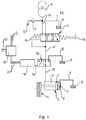
- FIG. 1 is a braking device 1, in particular a parking and / or emergency braking device, a tractor shown, wherein the braking device 1 is formed in the present case as a multi-disc brake.
- This is switched on or disengaged via a spring brake cylinder 2 serving as a brake application device, an engagement being effected via the force of a compression spring 3 and disengagement via a pressure acting in a pressure chamber 4, which acts hydraulically on a brake piston 5.
- a spring chamber 6 of the spring brake cylinder 2 is connected via a vent 7 with a tank 8.
- the corresponding hydraulic pressure medium to be supplied to the pressure chamber 4 is provided for a brake actuation via an accumulator 9, which is filled from a hydraulic system 10 of the tractor, for example the working hydraulics, via a check valve 11. From the accumulator leads a pressure line 12 to a manually operable second valve unit 13, which is in the form of a 3/3-way valve.
- the second valve unit 13 is actuated by means of an actuating device 14, here in the form of a manually operable hand lever, against the force of a return spring 15 in three switching positions.
- the 3/3-way valve 13 is a serving as a brake actuation valve 16 first valve unit 16 in the form of a 3/2-way valve 16 downstream.
- the 3/3-way valve 13 and that 3/2-way valve 16 are connected to each other via a working line 17.
- Serving as a brake actuation valve 16 3/2-way valve 16 is actuated via an actuating device 18, which causes a spool, not shown in detail, the first valve unit 16 and the 3/2-way valve 16 is inherently stable in its switching positions.
- the adjusting device 18 adjusts the 3/2-way valve 16 via a linkage 19 either in one of its two switching positions.
- the actuator 18 is connected to an electronic control device 20, which in turn is integrated in a CAN bus 21, to the control device 18 different data of the tractor, such as. about the operating state of the reciprocating internal combustion engine, operating state of the tractor operation, state of the parking brake, occupation of the cabin by the driver, errors in the electrical system, etc. are transmitted.
- the control device 20 has a power supply 22. From the control device 20 lead control lines 23 to the adjusting device 18, via which it is actuated.
- the first valve unit 13 or the 3/3-way valve 13 can be brought into a first switching position by actuation of the actuating device 14, in which it is in FIG. 1 is shown.
- the working line 17 is connected via a return line 24 to the tank 8, that is depressurized while the pressure line 12 is locked because the first valve unit 16 and the 3/2-way valve 16 is in a flow position , the pressure medium from the pressure chamber 4 can flow into the tank 8, so that the braking device 1 is engaged, so the tractor is braked.
- a reliable emergency braking function of the brake device 1 can be ensured, which enables manual braking of the vehicle, for example in the event of a failure of the first valve unit 16.
- the second valve unit 13 or the 3/3-way valve 13 can be adjusted by means of the actuating device 14, in particular exclusively manually, in a blocking position or in a flow position.
- the 3/2-way valve 16 has in addition to its in FIG. 1 set flow position in which it is the working line 17 with a brake line 25 connects, a drain position, in which the brake pipe 25 is connected to a return line 26.
Landscapes
- Engineering & Computer Science (AREA)
- Transportation (AREA)
- Mechanical Engineering (AREA)
- Braking Systems And Boosters (AREA)
- Valves And Accessory Devices For Braking Systems (AREA)
Abstract
Description
- Die Erfindung betrifft ein Steuersystem einer hydraulisch betätigten Bremseinrichtung eines land- oder bauwirtschaftlich nutzbaren Fahrzeugs, wobei Bremseinrichtung einen Federspeicherbremszylinder mit einem mit Druckmittel beaufschlagbaren Druckraum aufweist, der über eine erste Ventileinheit und eine zweite Ventileinheit mit einer als Druckspeicher ausgeführten Druckquelle verbindbar ist.
- Die Bremseinrichtung kann dabei als Feststell- und/oder Notbremseinrichtung genutzt werden. Feststellbremsen, die über eine automatische Betätigung verfügen und dabei elektronisch angesteuert werden, kommen zunehmend zur Komfortverbesserung an Traktoren zum Einsatz. Dabei ist von großer Bedeutung, dass die Bremsbetätigung nicht nur der Aufmerksamkeit des Fahrers überlassen wird, sondern abhängig von Situationen und Betriebszuständen des Traktors generell aktiviert wird. Von einem sich selbstständig in Bewegung setzenden Traktor gehen erhebliche Unfallgefahren aus, insbesondere dann, wenn der Fahrer im Heck- oder Frontbereich des Traktors an diesen Anbaugeräte an- oder abkuppelt sowie an diesen Anbaugeräten oder an den Kuppeleinrichtungen des Traktors Einstellungen vornimmt. Eine elektronisch ansteuerbare Feststellbremse ist außerdem von großer Bedeutung, wenn moderne Traktoren im Rahmen einer Leistungsverzweigung des Getriebes mit einem als CVT-Getriebe (Continuously Variable Transmission) versehen sind, so dass sich der Traktor im aktiven Stillstand bei nicht angetriebener Getriebeeingangswelle, also abgestellter Hubkolbenbrennkraftmaschine, in Bewegung setzen kann. Das kann beispielsweise auch dann der Fall sein, wenn die Hubkolbenbrennkraftmaschine aufgrund eines Kraftstoffmangels zum Stillstand kommt. Elektronisch ansteuerbare Feststellbremsen müssen daher hohe Anforderungen hinsichtlich ihrer funktionalen Sicherheit erfüllen, damit das Fahrzeug zum einen, wie dargelegt, sicher abgestellt werden kann, aber zum anderen auch die Feststellbremse nicht unbeabsichtigt während der Fahrt aktiviert wird, was zu unkontrollierbaren Fahrzuständen führen kann. Ein einfacher Fehler in der elektrohydraulischen Betätigung, bei dem zum Beispiel ein Bruch im Kabel eines Fahrzeug Kabelbaums auftritt, ist aufgrund des hohen Anteils an Straßenfahrten des Traktors, die dieser mit seiner hohen Gesamtmasse, zumeist mit Anhängern sowie einer hohen Geschwindigkeit durchführt, nicht akzeptabel. Von daher ist es von großer Bedeutung, dass die zumeist mit einem Federspeicherbremszylinder versehene Bremseinrichtung auch als Notbremseinrichtung verwendet werden kann, wenn die normale Betriebsbremse ausfällt oder deren Bremsmoment nicht ausreichend ist.
- Eine gattungsgemäße, hydraulisch betätigte, mit einem Federspeicherbremszylinder als Bremszuspanneinrichtung versehene Feststell- und/oder Notbremseinrichtung, ist aus der
DE 10 2008 030 511 A1 bekannt. Diese Bremsanlage weist eine Lamellenbremse auf, die über ein in einem Federspeicherbremszylinder angeordnetes Federelement eingerückt wird, um ein Bremsmoment zu erzeugen. Dieses Bremsmoment kann dadurch aufgehoben werden, dass in einem Druckraum des Federspeicherbremszylinders ein entgegen der Kraft des Federelements wirkender Druck aufgebaut wird. Dieser Druckaufbau in dem Druckraum wird ausgehend von einer als Druckspeicher ausgebildeten Druckquelle über eine erste als 3/2-Wegeventil ausgebildete Ventileinheit gesteuert. Diese als Bremsbetätigungventil dienende erste Ventileinheit wird in beiden Stellrichtungen über eine elektronische Steuereinheit elektromagnetisch betätigt, wobei die Steuereinheit unter anderem mit einem durch den Fahrer manuell verstellbaren Schaltelement verbunden ist. Bei einem Ausfall dieser Stelleinrichtung kann es jedoch zu sicherheitskritischem Ausfall der Bremseinrichtung kommen. - Es ist daher die Aufgabe der vorliegenden Erfindung, ein Steuersystem für eine hydraulisch betätigte Bremseinrichtung derart zu gestalten, dass die Funktionssicherheit der Bremseinrichtung, besonders deren Notbremsfunktion, verbessert werden kann.
- Diese Aufgabe wird, ausgehend von dem Oberbegriff des Patentanspruches 1 durch dessen kennzeichnende Merkmale gelöst. Vorteilhafte Ausgestaltungen sind in den abhängigen Patentansprüchen wiedergegeben, welche jeweils für sich genommen oder in Kombination miteinander einen Aspekt der Erfindung darstellen können.
- Ein Steuersystem einer hydraulisch betätigten Bremseinrichtung eines land- oder bauwirtschaftlich nutzbaren Fahrzeugs, wobei die Bremseinrichtung einen Federspeicherbremszylinder mit einem mit Druckmittel beaufschlagbaren Druckraum aufweist, der über ein in zwei Schaltstellungen aktuierbares, über eine elektronische Steuereinrichtung steuerbare erste Ventileinheit in Form eines Bremsbetätigungsventils und eine zweite Ventileinheit mit einer als Druckspeicher ausgeführten Druckquelle verbindbar ist. Gemäß der Erfindung ist zur Betätigung der Bremseinrichtung bei in einer Durchflussstellung geschalteten ersten Ventileinheit die zweite Ventileinheit mittels einer Betätigungsvorrichtung betätigbar. Bei einer Betätigung der zweiten Ventileinheit mittels der Betätigungsvorrichtung verbleibt die erste Ventileinheit, welche die Feststellbremsfunktion gewährleistet, inaktiv. Durch die Betätigung der zweiten Ventileinheit, welche ausschließlich als Hilfsbremse einsetzbar ist, kann eine zuverlässige Notbremsfunktion der Bremseinrichtung unabhängig von der ersten Ventileinheit gewährleistet werden. Hierdurch kann die Funktionssicherheit der Bremseinrichtung, besonders deren Notbremsfunktion, verbessert werden.
- In einer bevorzugten Ausgestaltung der Erfindung ist die zweite Ventileinheit als 3/3-Wegeventil ausgebildet ist, und eine Durchflussstellung, eine Sperrstellung und eine Ablaufstellung aufweist. Vorteilhafterweise sind die Betätigungsvorrichtung und/oder die zweite Ventileinheit nicht-festlegbar ausgebildet. Dies hat den Vorteil, dass eine reine Notbremsfunktion durch Betätigung der Betätigungsvorrichtung und/oder Aktivierung der zweiten Ventileinheit gewährleistet werden kann, ohne das die Gefahr besteht, dass die Bremseinrichtung dabei in einer Bremsstellung arretiert oder verharrt.
- Eine Signalübertragung von der Betätigungsvorrichtung zu der zweiten Ventileinheit erfolgt dabei vorteilhafterweise mechanisch, elektrisch und/oder fluidisch. Hierdurch kann eine Signalübertragung gewählt werden, welche effektiv konstruktiv sinnvoll in das Fahrzeug integrierbar ist.
- In einer weiterhin vorteilhaften Ausgestaltung der Erfindung ist die Betätigungsvorrichtung in Form eines, insbesondere ausschließlich, manuell betätigbaren Handhebels, Handtasters, oder Fußtasters, ausgebildet. Die Betätigungsvorrichtung ist dabei innerhalb der Kabine angeordnet. Durch die unterschiedlichen Ausgestaltungsformen kann die Betätigungsvorrichtung derart in die Kabine integriert werden, dass eine ergonomische und effektive Betätigung der Vorrichtung durch einen Bediener möglich ist, wodurch in einem Notfall ein zuverlässiges Bremsen des Fahrzeuges ermöglicht werden kann.
- Bevorzugt ist das Bremsbetätigungsventil als 3/2-Wegeventil ausgebildet, welches in einer ersten Schaltstellung die Druckquelle mit dem Druckraum und in einer zweiten Schaltstellung den Druckraum mit einem Rücklauf verbindet. Eine Stelleinrichtung des Bremsbetätigungsventils ist vorteilhafterweise derart ausgebildet, dass diese das Bremsbetätigungsventil in zumindest einer seiner Schaltstellungen eigenstabil hält, so dass dessen Steuerschieber ohne eine weitere Bestromung der Stelleinrichtung in einer zuletzt eingestellten Schaltstellung verbleibt. Damit wird verhindert, dass äußere Kräfte eine Änderung der vorgegebenen Schaltstellung des Steuerschiebers hervorrufen. Derartige äußere Kräfte können beispielsweise durch Erschütterungen oder Bauteilbewegungen am Traktor, die beim Überfahren von Fahrbahnunebenheiten auftreten, auf die Stelleinrichtung und auch auf eine Rastiereinrichtung übertragen werden. Dies hat den Vorteil, dass durch die innerhalb der Stelleinrichtung vorgesehene Hemmung eine hohe Funktionssicherheit gewährleistet wird, da so die Gefahr von Schaltbewegungen des Steuerschiebers äußere Kräfte verringert wird.
- Vorzugsweise ist das Bremsbetätigungsventil als bistabiles Wegeventil ausgeführt, dessen Steuerschieber ohne eine Bestromung seiner Stelleinrichtung in jeder seiner beiden zuletzt eingestellten Schaltstellungen verbleibt. Die Eigenstabilität kann dabei in einer oder in beiden Schaltstellungen, also auch bistabil wirken. Hierdurch kann die Funktionssicherheit weiter erhöht werden, da die Einflüsse äußerer Kräfte und daraus resultierender Schaltbewegungen weiter reduziert werden kann.
- In weiterer Ausgestaltung der Erfindung ist vorgesehen, dass die Stelleinrichtung einen selbsthemmenden Antrieb aufweist. Dabei weist die Stelleinrichtung beispielsweise einen von der Steuereinrichtung angesteuerten Elektromotor auf, der ein hochübersetztes Getriebe rotatorisch antreibt. Dies hat den Vorteil, dass die Eigenstabilität bzw. Hemmung der Stelleinrichtung eine ungewollte Schaltbewegung der Ventileinheit verhindert, wodurch die Funktionssicherheit weiter erhöht werden kann.
- Des Weiteren betrifft die Erfindung einen land- oder bauwirtschaftlich nutzbarer Traktor oder ein Systemfahrzeug mit einer hydraulisch betätigten Bremseinrichtung und mit mindestens einem wie vorstehen ausgebildeten und ausgestalteten Steuersystem.
- Die Erfindung ist nicht auf die angegebene Kombination der Merkmale des unabhängigen Patentanspruches 1 mit den von diesem abhängigen Patentansprüchen beschränkt. Es ergeben sich darüber hinaus Möglichkeiten, einzelne Merkmale, soweit sie aus den Patentansprüchen, den Vorteilsangaben zu den Patentansprüchen, der nachfolgenden Beschreibung des Ausführungsbeispiels oder zumindest aus den Zeichnungen hervorgehen, miteinander zu kombinieren. Die Bezugnahme der Patentansprüche auf die Zeichnung durch entsprechende Verwendung vom Bezugszeichen soll den Schutzumfang der Patentansprüche nicht beschränken.
- Zur weiteren Erläuterung der Erfindung wird auf die Zeichnung verwiesen, in der ein Ausführungsbeispiel der Erfindung vereinfacht dargestellt ist.
- Es zeigt:
- Fig. 1
- eine schematische Ansicht eines Steuersystems einer hydraulisch betätigten Bremseinrichtung eines land- oder bauwirtschaftlich nutzbaren Fahrzeugs, die über einen Federspeicherbremszylinder betätigbar ist, _wobei ein zur Steuerung des Federspeicherbremszylinders vorgesehenes Bremsbetätigungsventil mittels einer erfindungsgemäß ausgebildeten Stelleinrichtung aktuiert wird,
- In der
Figur 1 ist eine Bremseinrichtung 1, insbesondere eine Feststell- und/oder Notbremseinrichtung, eines Traktors dargestellt, wobei die Bremseinrichtung 1 im vorliegenden Fall als Lamellenbremse ausgebildet ist. Diese wird über einen als Bremszuspanneinrichtung dienenden Federspeicherbremszylinder 2 ein-oder ausgerückt, wobei ein Einrücken über die Kraft einer Druckfeder 3 und ein Ausrücken über einen in einem Druckraum 4 wirkenden Druck, der einen Bremskolben 5 hydraulisch beaufschlagt, bewirkt werden. Ein Federraum 6 des Federspeicherbremszylinders 2 ist über eine Entlüftung 7 mit einem Tank 8 verbunden. - Das entsprechende dem Druckraum 4 zuzuführende hydraulische Druckmittel wird dabei für eine Bremsbetätigung über einen Druckspeicher 9, der aus einem Hydrauliksystem 10 des Traktors, beispielsweise der Arbeitshydraulik, über ein Rückschlagventil 11 befüllt wird, zur Verfügung gestellt. Von dem Druckspeicher führt eine Druckleitung 12 zu einer manuell betätigbaren zweite Ventileinheit 13, welche in Form eines 3/3-Wegeventil ausgebildet ist. Die zweite Ventileinheit 13 ist mittels einer Betätigungsvorrichtung 14, hier in Form eines manuell betätigbaren Handhebels, entgegen der Kraft einer Rückstellfeder 15 in drei Schaltstellungen betätigbar.
- Dem 3/3-Wegeventil 13 ist eine als Bremsbetätigungsventil 16 dienende erste Ventileinheit 16 in Form eines 3/2-Wegeventil 16 nachgeschaltet. Das 3/3-Wegeventil 13 und dass 3/2-Wegeventil 16 sind dabei über eine Arbeitsleitung 17 miteinander verbunden. Das als Bremsbetätigungsventil 16 dienende 3/2-Wegeventil 16 ist über eine Stelleinrichtung 18 betätigbar, die bewirkt, dass ein im Einzelnen nicht dargestellter Steuerschieber der ersten Ventileinheit 16 bzw. des 3/2-Wegeventil 16 in seinen Schaltstellungen eigenstabil ist. Die Stelleinrichtung 18 verstellt das 3/2-Wegeventil 16 über ein Gestänge 19 wahlweise in eine seiner beiden Schaltstellungen.
- Die Stelleinrichtung 18 ist mit einer elektronischen Steuereinrichtung 20 verbunden, die ihrerseits in einen CAN-Bus 21 integriert ist, wobei an die Steuereinrichtung 18 unterschiedliche Daten des Traktors, wie z.B. über den Betriebszustand der Hubkolbenbrennkraftmaschine, Betriebszustand des Traktorgetriebes, Zustand der Feststellbremse, Besetzung der Kabine durch den Fahrer, Fehler im Bordnetz usw. übermittelt werden. Die Steuereinrichtung 20 weist eine Stromversorgung 22 auf. Von der Steuereinrichtung 20 führen Steuerleitungen 23 zur Stelleinrichtung 18, über die diese betätigt wird.
- Gemäß der Erfindung kann die kann die erste Ventileinheit 13 bzw. das 3/3-Wegeventil 13 durch Betätigung der Betätigungsvorrichtung 14 in eine erste Schaltstellung verbracht werden, in der es in
Figur 1 dargestellt ist. In der ersten Schaltstellung der zweiten Ventileinheit 13 ist die Arbeitsleitung 17 über eine Rücklaufleitung 24 mit dem Tank 8 verbunden, also drucklos, während die Druckleitung 12 gesperrt ist Da sich die erste Ventileinheit 16 bzw. das 3/2-Wegeventil 16 in einer Durchflussstellung befindet, kann das Druckmittel aus dem Druckraum 4 in den Tank 8 ausströmen, so dass die Bremseinrichtung 1 eingerückt wird, der Traktor sich also gebremst wird. Hierdurch kann eine zuverlässige Notbremsfunktion der Bremseinrichtung 1 gewährleistet werden, welche ein manuelles Bremsen des Fahrzeuges, beispielsweise bei einem Ausfall der ersten Ventileinheit 16, ermöglicht. - Darüber hinaus kann die zweite Ventileinheit 13 bzw. das 3/3-Wegeventil 13 mittels der Betätigungsvorrichtung 14, insbesondere ausschließlich manuell, in eine Sperrstellung oder in eine Durchflussstellung verstellt werden. Das 3/2-Wegeventil 16 weist neben seiner in
Figur 1 eingestellten Durchflussstellung, in der es die Arbeitsleitung 17 mit einer Bremsleitung 25 verbindet, eine Ablaufstellung ein, in der die Bremsleitung 25 mit einer Rücklaufleitung 26 verbunden ist. -
- 1
- Bremseinrichtung
- 2
- Federspeicherbremszylinder
- 3
- Druckfeder
- 4
- Druckraum
- 5
- Bremskolben
- 6
- Federraum
- 7
- Entlüftung
- 8
- Tank
- 9
- Druckspeicher
- 10
- Hydrauliksystem des Traktors
- 11
- Rückschlagventil
- 12
- Druckleitung
- 13
- 3/3-Wegeventil
- 14
- Manuelle Betätigungsvorrichtung
- 15
- Rückstellfeder
- 16
- 3/2-Wegeventil
- 17
- Arbeitsleitung
- 18
- Stelleinrichtung
- 19
- Gestänge
- 20
- elektronische Steuereinrichtung
- 21
- CAN-Bus
- 22
- Stromversorgung
- 23
- Steuerleitungen
- 24
- Rücklaufleitung von 12
- 25
- Bremsleitung
- 26
- Rücklaufleitung von 16
- 28
- Steuersystem
Claims (10)
- Steuersystem einer hydraulisch betätigten Bremseinrichtung (1) eines land- oder bauwirtschaftlich nutzbaren Fahrzeugs, wobei die Bremseinrichtung (1) einen Federspeicherbremszylinder (2) mit einem mit Druckmittel beaufschlagbaren Druckraum (4) aufweist, der über ein in zwei Schaltstellungen aktuierbares, über eine elektronische Steuereinrichtung (20) steuerbare erste Ventileinheit (16) in Form eines Bremsbetätigungsventils (16) und eine zweite Ventileinheit (13) mit einer als Druckspeicher (9) ausgeführten Druckquelle verbindbar ist,
dadurch gekennzeichnet, dass
zur Betätigung der Bremseinrichtung (1) bei in einer Durchflussstellung geschalteten ersten Ventileinheit (13) die zweite Ventileinheit (13) mittels einer Betätigungsvorrichtung (14) betätigbar ist. - Steuersystem nach Anspruch 1, dadurch gekennzeichnet, dass die zweite Ventileinheit (13) als 3/3-Wegeventil ausgebildet ist, und eine Durchflussstellung, eine Sperrstellung und eine Ablaufstellung aufweist.
- Steuersystem nach Anspruch 1 oder 2, dadurch gekennzeichnet, dass die Betätigungsvorrichtung (14) und/oder die zweite Ventileinheit (13) nicht-festlegbar ausgebildet ist.
- Steuersystem nach einem der vorherigen Ansprüche, dadurch gekennzeichnet, dass eine Signalübertragung von der Betätigungsvorrichtung (14) zu der zweiten Ventileinheit (13) mechanisch, elektrisch und/oder fluidisch erfolgt.
- Steuersystem nach einem der vorherigen Ansprüche, dadurch gekennzeichnet, dass die Betätigungsvorrichtung (14) in Form eines, insbesondere ausschließlich, manuell betätigbaren Handhebels, Handtasters, oder Fußtasters, ausgebildet ist.
- Steuersystem nach einem der vorherigen Ansprüche, dadurch gekennzeichnet, dass das Bremsbetätigungsventil (16) als 3/2-Wegeventil ausgebildet ist, das in einer ersten Schaltstellung die Druckquelle (9) mit dem Druckraum (4) und in einer zweiten Schaltstellung den Druckraum (4) mit einem Rücklauf (26) verbindet.
- Steuersystem nach einem der vorherigen Ansprüche, dadurch gekennzeichnet, dass eine Stelleinrichtung (18) des Bremsbetätigungsventils (16) derart ausgebildet ist, dass diese das Bremsbetätigungsventil (16) in zumindest einer seiner Schaltstellungen eigenstabil hält, so dass dessen Steuerschieber ohne eine weitere Bestromung der Stelleinrichtung (18) in einer zuletzt eingestellten Schaltstellung verbleibt.
- Steuersystem nach einem der vorherigen Ansprüche, dadurch gekennzeichnet, dass das Bremsbetätigungsventil (16) als bistabiles Wegeventil ausgeführt ist, dessen Steuerschieber ohne eine Bestromung seiner Stelleinrichtung (18) in jeder seiner beiden zuletzt eingestellten Schaltstellungen verbleibt.
- Steuersystem nach einem der vorherigen Ansprüche, dadurch gekennzeichnet, dass die Stelleinrichtung (18) einen selbsthemmenden Antrieb aufweist.
- Land- oder bauwirtschaftlich nutzbarer Traktor oder Systemfahrzeug mit einer hydraulisch betätigten Bremseinrichtung und mit mindestens einem Steuersystem nach einem der Ansprüche 1 bis 9.
Applications Claiming Priority (1)
| Application Number | Priority Date | Filing Date | Title |
|---|---|---|---|
| DE102017122772.5A DE102017122772A1 (de) | 2017-09-29 | 2017-09-29 | Steuersystem einer hydraulisch betätigten Bremseinrichtung |
Publications (2)
| Publication Number | Publication Date |
|---|---|
| EP3461707A1 true EP3461707A1 (de) | 2019-04-03 |
| EP3461707B1 EP3461707B1 (de) | 2021-06-16 |
Family
ID=63637656
Family Applications (1)
| Application Number | Title | Priority Date | Filing Date |
|---|---|---|---|
| EP18194009.9A Active EP3461707B1 (de) | 2017-09-29 | 2018-09-12 | Steuersystem einer hydraulisch betätigten bremseinrichtung |
Country Status (2)
| Country | Link |
|---|---|
| EP (1) | EP3461707B1 (de) |
| DE (1) | DE102017122772A1 (de) |
Cited By (1)
| Publication number | Priority date | Publication date | Assignee | Title |
|---|---|---|---|---|
| CN113944709A (zh) * | 2021-11-02 | 2022-01-18 | 湖北三江航天万山特种车辆有限公司 | 驻车制动系统和车辆 |
Families Citing this family (1)
| Publication number | Priority date | Publication date | Assignee | Title |
|---|---|---|---|---|
| DE102020121082A1 (de) * | 2020-08-11 | 2022-02-17 | Zf Cv Systems Europe Bv | Sekundärbremsanlage eines Fahrzeugs und Verfahren zu deren Steuerung |
Citations (4)
| Publication number | Priority date | Publication date | Assignee | Title |
|---|---|---|---|---|
| DE3447380A1 (de) * | 1984-12-24 | 1986-07-03 | Mannesmann Rexroth GmbH, 8770 Lohr | Vorrichtung zur sicherung einer zu einem verbraucher fuehrenden leitung |
| DE102008030511A1 (de) | 2008-06-27 | 2010-01-14 | Agco Gmbh | Bremsanlage für Fahrzeug |
| DE102012106213A1 (de) * | 2012-07-11 | 2014-01-16 | Linde Material Handling Gmbh | Arbeitsmaschine mit einem elektrischen Antriebssystem |
| EP3300976A1 (de) * | 2016-09-28 | 2018-04-04 | CLAAS Tractor S.A.S. | Steuereinrichtung und steuersystem einer hydraulisch betätigten feststell- und/oder notbremseinrichtung eines land- oder bauwirtschaftlich nutzbaren fahrzeugs |
-
2017
- 2017-09-29 DE DE102017122772.5A patent/DE102017122772A1/de not_active Withdrawn
-
2018
- 2018-09-12 EP EP18194009.9A patent/EP3461707B1/de active Active
Patent Citations (4)
| Publication number | Priority date | Publication date | Assignee | Title |
|---|---|---|---|---|
| DE3447380A1 (de) * | 1984-12-24 | 1986-07-03 | Mannesmann Rexroth GmbH, 8770 Lohr | Vorrichtung zur sicherung einer zu einem verbraucher fuehrenden leitung |
| DE102008030511A1 (de) | 2008-06-27 | 2010-01-14 | Agco Gmbh | Bremsanlage für Fahrzeug |
| DE102012106213A1 (de) * | 2012-07-11 | 2014-01-16 | Linde Material Handling Gmbh | Arbeitsmaschine mit einem elektrischen Antriebssystem |
| EP3300976A1 (de) * | 2016-09-28 | 2018-04-04 | CLAAS Tractor S.A.S. | Steuereinrichtung und steuersystem einer hydraulisch betätigten feststell- und/oder notbremseinrichtung eines land- oder bauwirtschaftlich nutzbaren fahrzeugs |
Cited By (1)
| Publication number | Priority date | Publication date | Assignee | Title |
|---|---|---|---|---|
| CN113944709A (zh) * | 2021-11-02 | 2022-01-18 | 湖北三江航天万山特种车辆有限公司 | 驻车制动系统和车辆 |
Also Published As
| Publication number | Publication date |
|---|---|
| EP3461707B1 (de) | 2021-06-16 |
| DE102017122772A1 (de) | 2019-04-04 |
Similar Documents
| Publication | Publication Date | Title |
|---|---|---|
| EP0552649B1 (de) | Parkbremssteuersystem | |
| EP1743823B1 (de) | Antriebssystem eines Arbeitsfahrzeugs | |
| DE102005002699B4 (de) | Bremsventilanordung | |
| EP1199234B1 (de) | Notentriegelungseinrichtung für die Parksperre eines Kraftfahrzeugs | |
| EP3473509B1 (de) | Bremsmodul für ein hydraulisch gebremstes zugfahrzeug, welches mit einem pneumatisch gebremsten anhängefahrzeug koppelbar ist | |
| EP3954591B1 (de) | Sekundärbremsanlage eines fahrzeugs und verfahren zu deren steuerung | |
| EP3730363B1 (de) | Hydrauliksystem und fahrzeug | |
| EP3300976B1 (de) | Steuereinrichtung und steuersystem einer hydraulisch betätigten feststell- und/oder notbremseinrichtung eines land- oder bauwirtschaftlich nutzbaren fahrzeugs | |
| EP3461707B1 (de) | Steuersystem einer hydraulisch betätigten bremseinrichtung | |
| EP2712787B1 (de) | Landwirtschaftliches Fahrzeug mit Servolenkung | |
| DE102009031742A1 (de) | Fahrbare Arbeitsmaschine mit einer als Betriebsbremse und als automatische Feststellbremse betreibbaren Bremse | |
| EP3305611B1 (de) | Bremsvorrichtung | |
| EP3944997B1 (de) | Fahrzeugbremsanlage und landwirtschaftliches zugfahrzeug | |
| EP4069560B1 (de) | Ausfallsicherheitsventileinheit für eine parkbremsfunktion sowie parkbremsventilanordnung | |
| EP3738843B1 (de) | Hydrauliksystem | |
| DE19928249B4 (de) | Einrichtung zur Steuerung wenigstens eines hydraulischen Antriebsaggregats | |
| DE102009005009A1 (de) | Fahrbare Arbeitsmaschine mit hydraulisch lösbarer Federspeicherbremse | |
| DE8615387U1 (de) | Kraftfahrzeug, insbesondere im Stop-and-Go-Verkehr betriebenes Nutzfahrzeug | |
| EP3996962B1 (de) | Parkbremseinrichtung | |
| DE102017200324B4 (de) | Verfahren zum Betreiben eines Bremssystems für ein Kraftfahrzeug sowie entsprechendes Bremssystem | |
| EP4396050A1 (de) | Anhängersteuerventil eines zugfahrzeugs | |
| DE10134789A1 (de) | Fahrantrieb für ein Kraftfahrzeug | |
| EP2234829B1 (de) | Hydraulische absicherung einer wankstabilisierung | |
| DE102008021203A1 (de) | Bremssystem | |
| DE102016108178A1 (de) | Bremssteuerungssystem einer mobilen Arbeitsmaschine |
Legal Events
| Date | Code | Title | Description |
|---|---|---|---|
| STAA | Information on the status of an ep patent application or granted ep patent |
Free format text: STATUS: UNKNOWN |
|
| PUAI | Public reference made under article 153(3) epc to a published international application that has entered the european phase |
Free format text: ORIGINAL CODE: 0009012 |
|
| STAA | Information on the status of an ep patent application or granted ep patent |
Free format text: STATUS: THE APPLICATION HAS BEEN PUBLISHED |
|
| AK | Designated contracting states |
Kind code of ref document: A1 Designated state(s): AL AT BE BG CH CY CZ DE DK EE ES FI FR GB GR HR HU IE IS IT LI LT LU LV MC MK MT NL NO PL PT RO RS SE SI SK SM TR |
|
| AX | Request for extension of the european patent |
Extension state: BA ME |
|
| STAA | Information on the status of an ep patent application or granted ep patent |
Free format text: STATUS: REQUEST FOR EXAMINATION WAS MADE |
|
| 17P | Request for examination filed |
Effective date: 20191004 |
|
| RBV | Designated contracting states (corrected) |
Designated state(s): AL AT BE BG CH CY CZ DE DK EE ES FI FR GB GR HR HU IE IS IT LI LT LU LV MC MK MT NL NO PL PT RO RS SE SI SK SM TR |
|
| STAA | Information on the status of an ep patent application or granted ep patent |
Free format text: STATUS: EXAMINATION IS IN PROGRESS |
|
| 17Q | First examination report despatched |
Effective date: 20200609 |
|
| GRAJ | Information related to disapproval of communication of intention to grant by the applicant or resumption of examination proceedings by the epo deleted |
Free format text: ORIGINAL CODE: EPIDOSDIGR1 |
|
| GRAP | Despatch of communication of intention to grant a patent |
Free format text: ORIGINAL CODE: EPIDOSNIGR1 |
|
| INTG | Intention to grant announced |
Effective date: 20201202 |
|
| INTG | Intention to grant announced |
Effective date: 20201209 |
|
| INTC | Intention to grant announced (deleted) | ||
| GRAP | Despatch of communication of intention to grant a patent |
Free format text: ORIGINAL CODE: EPIDOSNIGR1 |
|
| STAA | Information on the status of an ep patent application or granted ep patent |
Free format text: STATUS: GRANT OF PATENT IS INTENDED |
|
| INTG | Intention to grant announced |
Effective date: 20210120 |
|
| GRAS | Grant fee paid |
Free format text: ORIGINAL CODE: EPIDOSNIGR3 |
|
| GRAA | (expected) grant |
Free format text: ORIGINAL CODE: 0009210 |
|
| STAA | Information on the status of an ep patent application or granted ep patent |
Free format text: STATUS: THE PATENT HAS BEEN GRANTED |
|
| AK | Designated contracting states |
Kind code of ref document: B1 Designated state(s): AL AT BE BG CH CY CZ DE DK EE ES FI FR GB GR HR HU IE IS IT LI LT LU LV MC MK MT NL NO PL PT RO RS SE SI SK SM TR |
|
| REG | Reference to a national code |
Ref country code: GB Ref legal event code: FG4D Free format text: NOT ENGLISH |
|
| REG | Reference to a national code |
Ref country code: CH Ref legal event code: EP |
|
| REG | Reference to a national code |
Ref country code: DE Ref legal event code: R096 Ref document number: 502018005716 Country of ref document: DE |
|
| REG | Reference to a national code |
Ref country code: AT Ref legal event code: REF Ref document number: 1402096 Country of ref document: AT Kind code of ref document: T Effective date: 20210715 |
|
| REG | Reference to a national code |
Ref country code: IE Ref legal event code: FG4D Free format text: LANGUAGE OF EP DOCUMENT: GERMAN |
|
| REG | Reference to a national code |
Ref country code: LT Ref legal event code: MG9D |
|
| PG25 | Lapsed in a contracting state [announced via postgrant information from national office to epo] |
Ref country code: BG Free format text: LAPSE BECAUSE OF FAILURE TO SUBMIT A TRANSLATION OF THE DESCRIPTION OR TO PAY THE FEE WITHIN THE PRESCRIBED TIME-LIMIT Effective date: 20210916 Ref country code: HR Free format text: LAPSE BECAUSE OF FAILURE TO SUBMIT A TRANSLATION OF THE DESCRIPTION OR TO PAY THE FEE WITHIN THE PRESCRIBED TIME-LIMIT Effective date: 20210616 Ref country code: LT Free format text: LAPSE BECAUSE OF FAILURE TO SUBMIT A TRANSLATION OF THE DESCRIPTION OR TO PAY THE FEE WITHIN THE PRESCRIBED TIME-LIMIT Effective date: 20210616 Ref country code: FI Free format text: LAPSE BECAUSE OF FAILURE TO SUBMIT A TRANSLATION OF THE DESCRIPTION OR TO PAY THE FEE WITHIN THE PRESCRIBED TIME-LIMIT Effective date: 20210616 |
|
| REG | Reference to a national code |
Ref country code: NL Ref legal event code: MP Effective date: 20210616 |
|
| PG25 | Lapsed in a contracting state [announced via postgrant information from national office to epo] |
Ref country code: SE Free format text: LAPSE BECAUSE OF FAILURE TO SUBMIT A TRANSLATION OF THE DESCRIPTION OR TO PAY THE FEE WITHIN THE PRESCRIBED TIME-LIMIT Effective date: 20210616 Ref country code: RS Free format text: LAPSE BECAUSE OF FAILURE TO SUBMIT A TRANSLATION OF THE DESCRIPTION OR TO PAY THE FEE WITHIN THE PRESCRIBED TIME-LIMIT Effective date: 20210616 Ref country code: LV Free format text: LAPSE BECAUSE OF FAILURE TO SUBMIT A TRANSLATION OF THE DESCRIPTION OR TO PAY THE FEE WITHIN THE PRESCRIBED TIME-LIMIT Effective date: 20210616 Ref country code: NO Free format text: LAPSE BECAUSE OF FAILURE TO SUBMIT A TRANSLATION OF THE DESCRIPTION OR TO PAY THE FEE WITHIN THE PRESCRIBED TIME-LIMIT Effective date: 20210916 Ref country code: GR Free format text: LAPSE BECAUSE OF FAILURE TO SUBMIT A TRANSLATION OF THE DESCRIPTION OR TO PAY THE FEE WITHIN THE PRESCRIBED TIME-LIMIT Effective date: 20210917 |
|
| PG25 | Lapsed in a contracting state [announced via postgrant information from national office to epo] |
Ref country code: NL Free format text: LAPSE BECAUSE OF FAILURE TO SUBMIT A TRANSLATION OF THE DESCRIPTION OR TO PAY THE FEE WITHIN THE PRESCRIBED TIME-LIMIT Effective date: 20210616 Ref country code: PT Free format text: LAPSE BECAUSE OF FAILURE TO SUBMIT A TRANSLATION OF THE DESCRIPTION OR TO PAY THE FEE WITHIN THE PRESCRIBED TIME-LIMIT Effective date: 20211018 Ref country code: RO Free format text: LAPSE BECAUSE OF FAILURE TO SUBMIT A TRANSLATION OF THE DESCRIPTION OR TO PAY THE FEE WITHIN THE PRESCRIBED TIME-LIMIT Effective date: 20210616 Ref country code: CZ Free format text: LAPSE BECAUSE OF FAILURE TO SUBMIT A TRANSLATION OF THE DESCRIPTION OR TO PAY THE FEE WITHIN THE PRESCRIBED TIME-LIMIT Effective date: 20210616 Ref country code: SM Free format text: LAPSE BECAUSE OF FAILURE TO SUBMIT A TRANSLATION OF THE DESCRIPTION OR TO PAY THE FEE WITHIN THE PRESCRIBED TIME-LIMIT Effective date: 20210616 Ref country code: SK Free format text: LAPSE BECAUSE OF FAILURE TO SUBMIT A TRANSLATION OF THE DESCRIPTION OR TO PAY THE FEE WITHIN THE PRESCRIBED TIME-LIMIT Effective date: 20210616 Ref country code: EE Free format text: LAPSE BECAUSE OF FAILURE TO SUBMIT A TRANSLATION OF THE DESCRIPTION OR TO PAY THE FEE WITHIN THE PRESCRIBED TIME-LIMIT Effective date: 20210616 Ref country code: ES Free format text: LAPSE BECAUSE OF FAILURE TO SUBMIT A TRANSLATION OF THE DESCRIPTION OR TO PAY THE FEE WITHIN THE PRESCRIBED TIME-LIMIT Effective date: 20210616 |
|
| PG25 | Lapsed in a contracting state [announced via postgrant information from national office to epo] |
Ref country code: PL Free format text: LAPSE BECAUSE OF FAILURE TO SUBMIT A TRANSLATION OF THE DESCRIPTION OR TO PAY THE FEE WITHIN THE PRESCRIBED TIME-LIMIT Effective date: 20210616 |
|
| REG | Reference to a national code |
Ref country code: DE Ref legal event code: R097 Ref document number: 502018005716 Country of ref document: DE |
|
| PLBE | No opposition filed within time limit |
Free format text: ORIGINAL CODE: 0009261 |
|
| STAA | Information on the status of an ep patent application or granted ep patent |
Free format text: STATUS: NO OPPOSITION FILED WITHIN TIME LIMIT |
|
| PG25 | Lapsed in a contracting state [announced via postgrant information from national office to epo] |
Ref country code: DK Free format text: LAPSE BECAUSE OF FAILURE TO SUBMIT A TRANSLATION OF THE DESCRIPTION OR TO PAY THE FEE WITHIN THE PRESCRIBED TIME-LIMIT Effective date: 20210616 |
|
| REG | Reference to a national code |
Ref country code: CH Ref legal event code: PL |
|
| 26N | No opposition filed |
Effective date: 20220317 |
|
| PG25 | Lapsed in a contracting state [announced via postgrant information from national office to epo] |
Ref country code: MC Free format text: LAPSE BECAUSE OF FAILURE TO SUBMIT A TRANSLATION OF THE DESCRIPTION OR TO PAY THE FEE WITHIN THE PRESCRIBED TIME-LIMIT Effective date: 20210616 Ref country code: AL Free format text: LAPSE BECAUSE OF FAILURE TO SUBMIT A TRANSLATION OF THE DESCRIPTION OR TO PAY THE FEE WITHIN THE PRESCRIBED TIME-LIMIT Effective date: 20210616 |
|
| PG25 | Lapsed in a contracting state [announced via postgrant information from national office to epo] |
Ref country code: LU Free format text: LAPSE BECAUSE OF NON-PAYMENT OF DUE FEES Effective date: 20210912 Ref country code: IT Free format text: LAPSE BECAUSE OF FAILURE TO SUBMIT A TRANSLATION OF THE DESCRIPTION OR TO PAY THE FEE WITHIN THE PRESCRIBED TIME-LIMIT Effective date: 20210616 Ref country code: IE Free format text: LAPSE BECAUSE OF NON-PAYMENT OF DUE FEES Effective date: 20210912 |
|
| PG25 | Lapsed in a contracting state [announced via postgrant information from national office to epo] |
Ref country code: LI Free format text: LAPSE BECAUSE OF NON-PAYMENT OF DUE FEES Effective date: 20210930 Ref country code: CH Free format text: LAPSE BECAUSE OF NON-PAYMENT OF DUE FEES Effective date: 20210930 |
|
| GBPC | Gb: european patent ceased through non-payment of renewal fee |
Effective date: 20220912 |
|
| P01 | Opt-out of the competence of the unified patent court (upc) registered |
Effective date: 20230516 |
|
| PG25 | Lapsed in a contracting state [announced via postgrant information from national office to epo] |
Ref country code: CY Free format text: LAPSE BECAUSE OF FAILURE TO SUBMIT A TRANSLATION OF THE DESCRIPTION OR TO PAY THE FEE WITHIN THE PRESCRIBED TIME-LIMIT Effective date: 20210616 |
|
| PG25 | Lapsed in a contracting state [announced via postgrant information from national office to epo] |
Ref country code: HU Free format text: LAPSE BECAUSE OF FAILURE TO SUBMIT A TRANSLATION OF THE DESCRIPTION OR TO PAY THE FEE WITHIN THE PRESCRIBED TIME-LIMIT; INVALID AB INITIO Effective date: 20180912 |
|
| PG25 | Lapsed in a contracting state [announced via postgrant information from national office to epo] |
Ref country code: GB Free format text: LAPSE BECAUSE OF NON-PAYMENT OF DUE FEES Effective date: 20220912 |
|
| PGFP | Annual fee paid to national office [announced via postgrant information from national office to epo] |
Ref country code: FR Payment date: 20230928 Year of fee payment: 6 Ref country code: DE Payment date: 20230920 Year of fee payment: 6 Ref country code: BE Payment date: 20230920 Year of fee payment: 6 |
|
| PG25 | Lapsed in a contracting state [announced via postgrant information from national office to epo] |
Ref country code: MK Free format text: LAPSE BECAUSE OF FAILURE TO SUBMIT A TRANSLATION OF THE DESCRIPTION OR TO PAY THE FEE WITHIN THE PRESCRIBED TIME-LIMIT Effective date: 20210616 |
|
| PG25 | Lapsed in a contracting state [announced via postgrant information from national office to epo] |
Ref country code: TR Free format text: LAPSE BECAUSE OF FAILURE TO SUBMIT A TRANSLATION OF THE DESCRIPTION OR TO PAY THE FEE WITHIN THE PRESCRIBED TIME-LIMIT Effective date: 20210616 |