EP3738843B1 - Hydrauliksystem - Google Patents
Hydrauliksystem Download PDFInfo
- Publication number
- EP3738843B1 EP3738843B1 EP20174049.5A EP20174049A EP3738843B1 EP 3738843 B1 EP3738843 B1 EP 3738843B1 EP 20174049 A EP20174049 A EP 20174049A EP 3738843 B1 EP3738843 B1 EP 3738843B1
- Authority
- EP
- European Patent Office
- Prior art keywords
- vehicle
- hydraulic
- brake system
- brake
- braking
- Prior art date
- Legal status (The legal status is an assumption and is not a legal conclusion. Google has not performed a legal analysis and makes no representation as to the accuracy of the status listed.)
- Active
Links
- 239000012530 fluid Substances 0.000 claims description 10
- 230000000694 effects Effects 0.000 claims description 4
- 238000000926 separation method Methods 0.000 claims description 3
- 238000001816 cooling Methods 0.000 description 7
- 230000005540 biological transmission Effects 0.000 description 5
- 238000006073 displacement reaction Methods 0.000 description 4
- 238000011144 upstream manufacturing Methods 0.000 description 4
- 230000000712 assembly Effects 0.000 description 3
- 238000000429 assembly Methods 0.000 description 3
- 238000003306 harvesting Methods 0.000 description 3
- 238000002955 isolation Methods 0.000 description 3
- 230000004913 activation Effects 0.000 description 2
- 238000002485 combustion reaction Methods 0.000 description 2
- 230000001419 dependent effect Effects 0.000 description 2
- 238000011161 development Methods 0.000 description 2
- 230000018109 developmental process Effects 0.000 description 2
- 230000000750 progressive effect Effects 0.000 description 2
- 238000010276 construction Methods 0.000 description 1
- 238000010586 diagram Methods 0.000 description 1
- 230000001105 regulatory effect Effects 0.000 description 1
Images


Classifications
-
- B—PERFORMING OPERATIONS; TRANSPORTING
- B60—VEHICLES IN GENERAL
- B60T—VEHICLE BRAKE CONTROL SYSTEMS OR PARTS THEREOF; BRAKE CONTROL SYSTEMS OR PARTS THEREOF, IN GENERAL; ARRANGEMENT OF BRAKING ELEMENTS ON VEHICLES IN GENERAL; PORTABLE DEVICES FOR PREVENTING UNWANTED MOVEMENT OF VEHICLES; VEHICLE MODIFICATIONS TO FACILITATE COOLING OF BRAKES
- B60T10/00—Control or regulation for continuous braking making use of fluid or powdered medium, e.g. for use when descending a long slope
- B60T10/04—Control or regulation for continuous braking making use of fluid or powdered medium, e.g. for use when descending a long slope with hydrostatic brake
-
- B—PERFORMING OPERATIONS; TRANSPORTING
- B60—VEHICLES IN GENERAL
- B60T—VEHICLE BRAKE CONTROL SYSTEMS OR PARTS THEREOF; BRAKE CONTROL SYSTEMS OR PARTS THEREOF, IN GENERAL; ARRANGEMENT OF BRAKING ELEMENTS ON VEHICLES IN GENERAL; PORTABLE DEVICES FOR PREVENTING UNWANTED MOVEMENT OF VEHICLES; VEHICLE MODIFICATIONS TO FACILITATE COOLING OF BRAKES
- B60T13/00—Transmitting braking action from initiating means to ultimate brake actuator with power assistance or drive; Brake systems incorporating such transmitting means, e.g. air-pressure brake systems
- B60T13/10—Transmitting braking action from initiating means to ultimate brake actuator with power assistance or drive; Brake systems incorporating such transmitting means, e.g. air-pressure brake systems with fluid assistance, drive, or release
- B60T13/58—Combined or convertible systems
- B60T13/585—Combined or convertible systems comprising friction brakes and retarders
-
- B—PERFORMING OPERATIONS; TRANSPORTING
- B60—VEHICLES IN GENERAL
- B60T—VEHICLE BRAKE CONTROL SYSTEMS OR PARTS THEREOF; BRAKE CONTROL SYSTEMS OR PARTS THEREOF, IN GENERAL; ARRANGEMENT OF BRAKING ELEMENTS ON VEHICLES IN GENERAL; PORTABLE DEVICES FOR PREVENTING UNWANTED MOVEMENT OF VEHICLES; VEHICLE MODIFICATIONS TO FACILITATE COOLING OF BRAKES
- B60T1/00—Arrangements of braking elements, i.e. of those parts where braking effect occurs specially for vehicles
- B60T1/02—Arrangements of braking elements, i.e. of those parts where braking effect occurs specially for vehicles acting by retarding wheels
- B60T1/06—Arrangements of braking elements, i.e. of those parts where braking effect occurs specially for vehicles acting by retarding wheels acting otherwise than on tread, e.g. employing rim, drum, disc, or transmission or on double wheels
- B60T1/065—Arrangements of braking elements, i.e. of those parts where braking effect occurs specially for vehicles acting by retarding wheels acting otherwise than on tread, e.g. employing rim, drum, disc, or transmission or on double wheels employing disc
-
- B—PERFORMING OPERATIONS; TRANSPORTING
- B60—VEHICLES IN GENERAL
- B60T—VEHICLE BRAKE CONTROL SYSTEMS OR PARTS THEREOF; BRAKE CONTROL SYSTEMS OR PARTS THEREOF, IN GENERAL; ARRANGEMENT OF BRAKING ELEMENTS ON VEHICLES IN GENERAL; PORTABLE DEVICES FOR PREVENTING UNWANTED MOVEMENT OF VEHICLES; VEHICLE MODIFICATIONS TO FACILITATE COOLING OF BRAKES
- B60T1/00—Arrangements of braking elements, i.e. of those parts where braking effect occurs specially for vehicles
- B60T1/02—Arrangements of braking elements, i.e. of those parts where braking effect occurs specially for vehicles acting by retarding wheels
- B60T1/08—Arrangements of braking elements, i.e. of those parts where braking effect occurs specially for vehicles acting by retarding wheels using fluid or powdered medium
- B60T1/093—Arrangements of braking elements, i.e. of those parts where braking effect occurs specially for vehicles acting by retarding wheels using fluid or powdered medium in hydrostatic, i.e. positive displacement, retarders
-
- B—PERFORMING OPERATIONS; TRANSPORTING
- B62—LAND VEHICLES FOR TRAVELLING OTHERWISE THAN ON RAILS
- B62D—MOTOR VEHICLES; TRAILERS
- B62D49/00—Tractors
- B62D49/06—Tractors adapted for multi-purpose use
- B62D49/0664—Light, simple, and economical tractors
- B62D49/0671—Light, simple, and economical tractors the driver riding on the tractor
-
- B—PERFORMING OPERATIONS; TRANSPORTING
- B62—LAND VEHICLES FOR TRAVELLING OTHERWISE THAN ON RAILS
- B62D—MOTOR VEHICLES; TRAILERS
- B62D53/00—Tractor-trailer combinations; Road trains
-
- F—MECHANICAL ENGINEERING; LIGHTING; HEATING; WEAPONS; BLASTING
- F15—FLUID-PRESSURE ACTUATORS; HYDRAULICS OR PNEUMATICS IN GENERAL
- F15B—SYSTEMS ACTING BY MEANS OF FLUIDS IN GENERAL; FLUID-PRESSURE ACTUATORS, e.g. SERVOMOTORS; DETAILS OF FLUID-PRESSURE SYSTEMS, NOT OTHERWISE PROVIDED FOR
- F15B13/00—Details of servomotor systems ; Valves for servomotor systems
- F15B13/02—Fluid distribution or supply devices characterised by their adaptation to the control of servomotors
- F15B13/025—Pressure reducing valves
-
- F—MECHANICAL ENGINEERING; LIGHTING; HEATING; WEAPONS; BLASTING
- F15—FLUID-PRESSURE ACTUATORS; HYDRAULICS OR PNEUMATICS IN GENERAL
- F15B—SYSTEMS ACTING BY MEANS OF FLUIDS IN GENERAL; FLUID-PRESSURE ACTUATORS, e.g. SERVOMOTORS; DETAILS OF FLUID-PRESSURE SYSTEMS, NOT OTHERWISE PROVIDED FOR
- F15B21/00—Common features of fluid actuator systems; Fluid-pressure actuator systems or details thereof, not covered by any other group of this subclass
- F15B21/08—Servomotor systems incorporating electrically operated control means
-
- F—MECHANICAL ENGINEERING; LIGHTING; HEATING; WEAPONS; BLASTING
- F16—ENGINEERING ELEMENTS AND UNITS; GENERAL MEASURES FOR PRODUCING AND MAINTAINING EFFECTIVE FUNCTIONING OF MACHINES OR INSTALLATIONS; THERMAL INSULATION IN GENERAL
- F16D—COUPLINGS FOR TRANSMITTING ROTATION; CLUTCHES; BRAKES
- F16D57/00—Liquid-resistance brakes; Brakes using the internal friction of fluids or fluid-like media, e.g. powders
- F16D57/06—Liquid-resistance brakes; Brakes using the internal friction of fluids or fluid-like media, e.g. powders comprising a pump circulating fluid, braking being effected by throttling of the circulation
-
- B—PERFORMING OPERATIONS; TRANSPORTING
- B60—VEHICLES IN GENERAL
- B60T—VEHICLE BRAKE CONTROL SYSTEMS OR PARTS THEREOF; BRAKE CONTROL SYSTEMS OR PARTS THEREOF, IN GENERAL; ARRANGEMENT OF BRAKING ELEMENTS ON VEHICLES IN GENERAL; PORTABLE DEVICES FOR PREVENTING UNWANTED MOVEMENT OF VEHICLES; VEHICLE MODIFICATIONS TO FACILITATE COOLING OF BRAKES
- B60T7/00—Brake-action initiating means
- B60T7/02—Brake-action initiating means for personal initiation
- B60T7/04—Brake-action initiating means for personal initiation foot actuated
- B60T7/042—Brake-action initiating means for personal initiation foot actuated by electrical means, e.g. using travel or force sensors
-
- B—PERFORMING OPERATIONS; TRANSPORTING
- B60—VEHICLES IN GENERAL
- B60T—VEHICLE BRAKE CONTROL SYSTEMS OR PARTS THEREOF; BRAKE CONTROL SYSTEMS OR PARTS THEREOF, IN GENERAL; ARRANGEMENT OF BRAKING ELEMENTS ON VEHICLES IN GENERAL; PORTABLE DEVICES FOR PREVENTING UNWANTED MOVEMENT OF VEHICLES; VEHICLE MODIFICATIONS TO FACILITATE COOLING OF BRAKES
- B60T7/00—Brake-action initiating means
- B60T7/02—Brake-action initiating means for personal initiation
- B60T7/08—Brake-action initiating means for personal initiation hand actuated
- B60T7/085—Brake-action initiating means for personal initiation hand actuated by electrical means, e.g. travel, force sensors
Definitions
- the present invention relates to a hydraulic system of an agricultural or industrial vehicle, with at least one hydraulic pump, in particular a hydraulic pump that can be controlled as a function of the load and has variable delivery capacity, which can be effectively mechanically connected to a drive of the vehicle, at least one first braking system for reducing the speed of the vehicle by means of at least one friction brake, and a retarder system that can reduce the speed of the vehicle in addition to and/or independently of the first braking system, a vehicle and a vehicle combination.
- at least one hydraulic pump in particular a hydraulic pump that can be controlled as a function of the load and has variable delivery capacity, which can be effectively mechanically connected to a drive of the vehicle, at least one first braking system for reducing the speed of the vehicle by means of at least one friction brake, and a retarder system that can reduce the speed of the vehicle in addition to and/or independently of the first braking system, a vehicle and a vehicle combination.
- Hydraulic systems of this type are eg from the patent documents U.S. 2008/298977 A1 , EP 2 328 785 A1 and DE 10 2012 112381 A1 known.
- a hydraulic system of an agricultural or industrial vehicle has at least one hydraulic pump, in particular a load-dependent controllable hydraulic pump with variable delivery capacity, which can be effectively mechanically connected to a drive of the vehicle, and at least a first braking system to reduce the speed of the vehicle by means of at least one friction brake, and a continuous braking system, which can reduce the speed of the vehicle in addition to and/or independently of the first braking system.
- the endurance braking system in turn has at least one first retarder circuit which can interact with the hydraulic pump in such a way that kinetic energy is withdrawn from the vehicle by the endurance braking system via the hydraulic pump in order to cause the vehicle to decelerate. In this way, the vehicle can be decelerated using a hydraulic pump already on the vehicle for other purposes.
- the hydraulic pump can be provided, for example, in order to supply hydraulic medium or to apply hydraulic pressure to a braking and/or steering system, a/another assembly(s) of the vehicle and/or one/several attachment(s).
- the first retarder circuit has means for reducing the kinetic energy or converting the kinetic energy into heat
- means can preferably be provided to dissipate energy, in particular heat, absorbed in the hydraulic medium from the hydraulic system.
- These means can be designed in particular in the form of a cooler, wherein the cooler can be a special cooling device for the continuous braking system and/or a cooling device of the vehicle that is already present for other purposes, for example.
- the means can be designed in the manner of at least one pressure-limiting valve or at least one load orifice or at least have such.
- the quantity of hydraulic medium drawn off by the continuous braking system can be determined by means of an upstream proportional valve or one or more upstream switching valve(s).
- At least one braking means is preferably provided, by means of which at least the first braking system and/or the continuous braking system can be actuated.
- the brake means can be a brake pedal of the vehicle, for example.
- a control unit can be provided, via which the continuous braking system is controlled, in particular activated or deactivated, and/or via which the delay caused by the continuous braking system can be controlled. This preferably takes place as a function of the output of a sensor that is effectively connected to the control unit, in particular a displacement sensor that interacts with the braking means. If the braking means has a brake pedal or is designed as such, the control unit can evaluate an actuation or pedal travel of the brake pedal, which can then be interpreted as a measure of the desired deceleration.
- the control system preferably interacts with at least one proportional valve or one or more switching valve(s).
- a second retarder circuit is provided according to the invention, through which brake pressure can be applied to a brake system of a trailer device when the continuous braking system is activated.
- a trailer device can be braked or decelerated together with the vehicle or as a function of this, as a result of which "jack-knifing" or unfolding of a vehicle combination consisting of vehicle and trailer device can be counteracted.
- a system separating valve is provided between the second retarder circuit and the brake system of the trailer device, so that no oil exchange takes place between the retarder circuit and the brake system and/or no foamed hydraulic medium can get from the retarder circuit into the brake circuit. In this way, the proportion of air in the oil can be kept low.
- a vehicle with a drive in particular an internal combustion engine, and at least one hydraulic pump, for supplying at least one assembly of the vehicle with hydraulic pressure, the hydraulic pump being mechanically operatively connected to the drive, is equipped with such a hydraulic system
- an existing hydraulic pump can be used in order to implement wear-free braking. It is thus possible to dispense with further/separate means for generating continuous braking, which is inexpensive and simple.
- the vehicle is in particular an agricultural or industrial work vehicle, preferably in the form of a farm tractor or tractor.
- the vehicle can also be an agricultural harvesting machine, a self-propelled sprayer, a construction vehicle, an industrial transport/traction vehicle or any other suitable vehicle with a hydraulic pump for supplying an assembly and/or an attachment of the vehicle with hydraulic fluid.
- a vehicle combination with a vehicle described above and at least one trailer device makes it possible to brake the trailer device jointly and/or as a function of the vehicle in order to counteract jack-knifing or unfolding of the vehicle combination.
- the trailer device can be, for example, a transport trailer, a loading wagon, an agricultural device, for example a harvesting device such as a baler, a haymaking device, or any other, particularly agricultural device, such as a towed sprayer, a seed drill or the like.
- the drawing shows an agricultural vehicle 10 in the manner of a farm tractor or tractor, which forms a vehicle combination 12 together with a trailer device 11 .
- the vehicle 10 has a frame 13 which is supported on the ground 16 via front and rear wheels 14 .
- An operator workstation 20 is arranged in a cabin 18 .
- a brake pedal is provided in the operator's workplace 20, which is referred to below as brake means 22, and which acts on a service brake or a braking system 24 of the vehicle 10.
- the braking system 24 is designed in a known manner and can brake the vehicle by means of friction brakes 25, in particular in the manner of disc brakes, depending on a position of the braking means 22.
- Vehicle 10 also has a drive 26, which is only shown in outline, and a transmission 28, which is also only shown in outline.
- Both the drive 26 and the gear 28 can be designed in a known manner, which is why neither is discussed in detail here.
- the drive 26 is designed as an internal combustion engine.
- the trailer device 11 designed in the manner of a conventional transport trailer is attached to a trailer device 30 of the vehicle 10.
- This trailer device 11 is provided as an option. It can be any suitable trailer device 11, for example a loading wagon, an agricultural harvesting device, for example a baler, a hay-making device, or any other, in particular agricultural, device.
- a hydraulic system 32 is also provided on the vehicle 10 .
- a hydraulic pump 34 is mechanically effective with the drive 26 or the transmission 28, usually via a transmission input shaft 35, shown only in outline.
- the hydraulic pump 34 is provided in order to drive one or more assemblies (not shown) of the vehicle 10 or to supply them with hydraulic fluid.
- the assemblies can be, for example, the braking system 24 of the vehicle 10, a steering system (not shown), a lifting device or other suitable assemblies.
- the hydraulic pump 34 can also optionally supply the trailer device 11 with hydraulic medium.
- the hydraulic pump 34 can provide hydraulic fluid for a braking device 36 of the trailer device 11 that interacts with the braking system 24 .
- the hydraulic pump 34 is designed as a known hydraulic pump with a variable delivery volume, which can be regulated as a function of a load pressure and draws the hydraulic medium from a hydraulic medium reservoir 38 of the vehicle 10 .
- a retarder or continuous braking system 40 is provided, which can be used, for example, initially or before and/or in addition to the braking system 24, in particular in demanding braking situations, for example when driving downhill for a long time.
- the continuous braking system 40 has a vehicle retarder circuit, which is referred to below as the first retarder circuit 42, with a proportional valve 44 spring-loaded in the direction of its closed position 44.1, and a pressure-limiting valve 46, and a trailer retarder circuit, hereinafter referred to as the second retarder circuit 48, for the optional trailer device 11, with a towards its closed position 50.1. spring-loaded control valve 50, a switching valve 52, a metering orifice 54 and a relief orifice 56.
- a cooling device which is referred to below as a cooler 58 for short, and a brake valve 60 that can be actuated by the braking means 22 and a travel sensor 62 for determining the position of the braking means 22 are provided for cooling the hydraulic medium.
- the displacement sensor 62 interacts with a control unit 64 which, among other things, controls the braking system 24 of the vehicle 10 .
- it interacts with the continuous braking system 40 and controls the proportional valve 44 as a function of a position of the travel sensor 62 .
- the control unit 64 can bring the proportional valve 44 from its closed position 44.1 into a position 44.2 enabling a hydraulic flow.
- the proportional valve 44 of the first retarder circuit 42 is provided downstream of the hydraulic pump 34 and is connected to it via a first line 66 . Downstream of the proportional valve 44, the line 66 divides into a first line branch 66a, which leads hydraulic medium to the control valve 50 of the second retarder circuit 48, and a second line branch 66b, which leads hydraulic medium from the proportional valve 44 to the spring-loaded pressure-limiting valve 46. A third line section 66c transmits the pending load pressure to the hydraulic pump 34.
- the metering orifice 54 is arranged downstream of the pressure-limiting valve 46, with a control line 68 of the control valve 50 branching off from the second line section 66b upstream of the metering orifice 54 in such a way that the control valve 50 can be actuated with the back pressure of the metering orifice 54 in order to assume its open position 50.2 accordingly.
- the relief diaphragm 56 is connected downstream of the control valve 50 in the direction of the hydraulic medium reservoir 38 in order to control the correct brake pressure and to reduce the brake pressure. Hydraulic medium can flow back into the hydraulic medium reservoir 38 via the cooler 58 .
- Another hydraulic line 70 carries hydraulic fluid from the control valve 50 to the changeover valve 52 in order to apply brake pressure to it.
- the changeover valve 52 has a first position 52.1, in which it can supply the braking device 36 of the trailer device 11 with hydraulic fluid via the hydraulic line 70 and apply braking pressure, and a second, preloaded position 52.2, in which it simplifies the braking device 36 via the Brake valve 60 shown directly via a brake line 72 of the brake system 24 that is independent of the continuous braking system 40 Hydraulic fluid can supply.
- the switchover valve 52 assumes its first position 52.1 when a sufficiently high brake pressure is present in the hydraulic line 70 and thus in a control line 74 of the switchover valve 52. If the pressure in control line 74 is not sufficiently high or if brake means 22 is actuated so strongly by an operator that switchover valve 52 assumes its second position 52.2, hydraulic pump 34 is connected to the brake device via brake means 22 or brake valve 60 36 of the trailer device 11 connected.
- the switching valve 52 is designed in such a way that the braking system 24 can always override the pressure present in the continuous braking system 40 .
- the function of the continuous braking system 40 will now be discussed in more detail below. If the operator actuates the braking means 22 in a braking situation, this is recorded by the displacement sensor 62 . This transmits an output value to the control unit 64, which controls the proportional valve 44 as a function of the output value, so that this enables a flow of hydraulic medium in accordance with the output value of the travel sensor 62. The braking power is thus adjusted via the proportional valve 44 as a function of the travel of the braking means 22.
- the braking power of the continuous braking system 40 is implemented in the pressure-limiting valve 46 .
- the delivery rate of the hydraulic pump 34 is in turn controlled according to the load pressure present in the line 66 upstream of the pressure-limiting valve, as a result of which the kinetic energy of the vehicle 10 is reduced due to the mechanical connection of the hydraulic pump 34 to the drive 26 .
- the hydraulic medium dissipates the energy in the form of heat and is cooled via the cooler 58 according to the example shown. However, it is also conceivable that the hydraulic medium is cooled via a cooling device already provided on the vehicle 10 or also additionally by such a cooling device.
- a high braking power can be achieved over the entire speed range of the hydraulic pump 34 by the configuration shown above. Due to a linear power loss characteristic, the regulation can also be implemented very well.
- FIG. 3 shows how the best possible activation of the braking system 24 and the continuous braking system 40 can take place.
- an operator actuates the braking means 22.
- the control unit 64 evaluates the Pedal travel W off. This is interpreted as a measure of the desired deceleration or braking power B. Up to the maximum deceleration B max possible via the continuous braking system 40, braking takes place exclusively via this. If the pedal travel W increases further, the brake system 24 is activated.
- a trailer device 11 is attached to the vehicle 10, it can be advantageous if the trailer device 11 is also supplied with a braking signal by the continuous braking system 40. In this way, parallel braking of vehicle 10 and trailer 11 can take place and a "jack-knifing"/jack-knife effect, ie an undesired unfolding of vehicle 10 and trailer 11, can be prevented. As described above, this takes place via switchover valve 52, which is in its first position 52.1. However, if vehicle 10 is braked additionally or exclusively via brake system 24, switchover valve 52 assumes its second position 52.2, in which hydraulic pump 34 connected to the braking system 36 of the trailer device 11 in such a way that it is subjected to braking pressure by the hydraulic pump 34 .
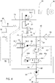
- FIG. 4 there is shown a second embodiment of the present invention in which a separation between the braking system 36 of the trailer implement 11 and the retarder system 40 is provided.
- a separation By providing a separation, no hydraulic fluid from the continuous braking system 40 can get into the braking system 36 of the trailer device 11, the proportion of air in the hydraulic fluid can be kept very low and/or no foamed hydraulic fluid can get out of the continuous braking system 40 into the braking system 36 of the trailer device 11 or the Brake system 24 of the vehicle 10 reach.
- a system separating valve 76 is provided to separate the braking systems 24, 36 and the continuous braking system 40.
- the system separating valve 76 has a housing 76.1 with an interior space 76.2, in which a piston 76.3 is movably accommodated against the action of a spring 76.4.
- the system separating valve 76 also has a first port A, a second port B and a third port C, with port A connected to the brake system 24 of the vehicle 10, port B to the brake system 36 of the trailer device 11 and port C via the Hydraulic line 70 is connected to the continuous braking system 40.
- the system isolation valve can have a first position in which it is as in the figure 5 a and b show a connection between terminals A and B and assume a second position in which the piston 76.3 is displaced against the action of the spring 76.4 by a pressure present at the connection C in such a way that a connection between the connections A and B is interrupted and the interior space 76.3 located Hydraulic medium is pressed via the connection C into the brake system 36 of the trailer device 11 in order to apply a brake pressure to it.
- FIG. 6 It will now open figure 6 reference is made to the drawing, in which a third embodiment of the invention is shown, which is substantially in accordance with the embodiment figure 4 is equivalent to.
- the variant shown differs from the one in figure 4 shown embodiment characterized in that the pressure relief valve 46 is replaced by a load orifice 78.
- Such a design is less expensive, but has a progressive rather than a linear characteristic, resulting in less braking power at speeds below the design speed and providing less good controllability.
- FIG 7 shown fourth exemplary embodiment corresponds again essentially to the exemplary embodiment according to FIG figure 4 , but differs in that the proportional valve 44 is replaced by one or more switching valves 80, with two switching valves 80 being used in the exemplary embodiment shown.
- Such a design is cheaper, but only allows the braking power to be adjusted in stages.
- FIG 8 shown fifth embodiment combines the features of the embodiments according to the figures 6 and 7 . This is the cheapest of the variants shown, but it only provides a gradual and progressive braking characteristic.
- a maximum continuous braking power is supported by a specially adapted transmission control, which increases the rotational speed of the drive 26 when the continuous braking system 40 is activated.
- any existing engine brake can also be used as a permanent brake.
Landscapes
- Engineering & Computer Science (AREA)
- Mechanical Engineering (AREA)
- Transportation (AREA)
- General Engineering & Computer Science (AREA)
- Chemical & Material Sciences (AREA)
- Combustion & Propulsion (AREA)
- Physics & Mathematics (AREA)
- Fluid Mechanics (AREA)
- Analytical Chemistry (AREA)
- Regulating Braking Force (AREA)
- Valves And Accessory Devices For Braking Systems (AREA)
- Transmission Of Braking Force In Braking Systems (AREA)
Description
- Die vorliegende Erfindung betrifft ein Hydrauliksystem eines landwirtschaftlichen oder industriellen Fahrzeugs, mit wenigstens einer, insbesondere lastabhängig steuerbaren Hydraulikpumpe mit variabler Förderleistung, die mechanisch wirksam mit einem Antrieb des Fahrzeugs verbindbar ist, wenigstens einem ersten Bremssystem zur Reduzierung der Geschwindigkeit des Fahrzeugs mittels wenigstens einer Reibungsbremse, und einem Dauerbremssystem, das zusätzlich zu und/oder unabhängig von dem ersten Bremssystem die Geschwindigkeit des Fahrzeugs reduzieren kann, ein Fahrzeug und eine Fahrzeugkombination.
- Hydrauliksysteme dieser Art sind z.B. aus den Patentdokumenten
US 2008/298977 A1 ,EP 2 328 785 A1 undDE 10 2012 112381 A1 bekannt. - Beim Bremsen schwerer Fahrzeuge müssen insbesondere bei langen Bergabfahrten hohe Energien umgewandelt werden. In derartigen Fällen kann es dazu kommen, dass die Kühlleistung eines üblichen, meist Reibungsbremsen, beispielsweise in der Art von Bremsscheiben, aufweisenden Bremssystems nicht ausreichend ist. Des Weiteren kann an dem Bremssystem bzw. an der/den Reibungsbremsen des Bremssystems ein Verschleiß entstehen, der die Lebensdauer verringern kann.
- Es ist bekannt, zur Reduzierung der Geschwindigkeit eines Fahrzeugs eine Motorbremse einzusetzen. Diese kann jedoch in der Leistung begrenzt sein und/oder keine optimale Regelung der Bremswirkung ermöglichen. Des Weiteren wird bei einer üblichen Motorbremse die Anhängerbremse nicht angesteuert, was zu schwierigen Fahrsituationen führen kann. Wird an einer Fahrzeugkombination ein Anhängegerät im Falle einer Dauerbremsung nicht oder zu wenig verzögert, so kann es zu einem sogenannten "Jack-Knifing", einem Auffalten der Fahrzeugkombination kommen.
- Die der Erfindung zugrundeliegende Aufgabe wird daher darin gesehen, ein Hydrauliksystem, ein Fahrzeug und eine Fahrzeugkombination vorzusehen, durch welche die vorgenannten Nachteile überwunden werden.
- Die Aufgabe wird erfindungsgemäß durch die Lehre des Patentanspruchs 1 gelöst. Weitere vorteilhafte Ausgestaltungen und Weiterbildungen der Erfindung gehen aus den Unteransprüchen hervor.
- Diesbezüglich weist ein Hydrauliksystem eines landwirtschaftlichen oder industriellen Fahrzeugs wenigstens eine, insbesondere lastabhängig steuerbare Hydraulikpumpe mit variabler Förderleistung, die mechanisch wirksam mit einem Antrieb des Fahrzeugs verbindbar ist, wenigstens ein erstes Bremssystem zur Reduzierung der Geschwindigkeit des Fahrzeugs mittels wenigstens einer Reibungsbremse, und ein Dauerbremssystem, das zusätzlich zu und/oder unabhängig von dem ersten Bremssystem die Geschwindigkeit des Fahrzeugs reduzieren kann, auf. Das Dauerbremssystem wiederum weist wenigstens einen ersten Retarderkreis auf, der mit der Hydraulikpumpe derart zusammenwirken kann, dass dem Fahrzeug durch das Dauerbremssystem über die Hydraulikpumpe Bewegungsenergie entzogen wird, um eine Verzögerung des Fahrzeugs zu bewirken. Auf diese Weise kann das Fahrzeug unter Verwendung einer bereits für andere Einsatzzwecke am Fahrzeug befindlichen Hydraulikpumpe verzögert werden. Dies kann die Anzahl an Bauteilen und/oder die Komplexität des Systems reduzieren und ist kostengünstig. Die Hydraulikpumpe kann beispielsweise vorgesehen sein, um ein Brems- und/oder Lenksystem, eine/andere Baugruppe(n) des Fahrzeugs und/oder ein/mehrere Anbaugerät(e) mit Hydraulikmittel zu versorgen bzw. mit Hydraulikdruck zu beaufschlagen.
- Weist der erste Retarderkreis Mittel zur Reduzierung der Bewegungsenergie bzw. einer Umwandlung der Bewegungsenergie in Wärme auf, können vorzugsweise Mittel vorgesehen sein, um in dem Hydraulikmittel aufgenommene Energie, insbesondere Wärme, aus dem Hydrauliksystem abzuführen. Diese Mittel können insbesondere in der Art eines Kühlers ausgebildet sein, wobei es sich bei dem Kühler um eine spezielle Kühleinrichtung für das Dauerbremssystem und/oder eine, beispielsweise bereits für andere Einsatzzwecke vorhandene Kühleinrichtung des Fahrzeugs handeln kann.
- Die Mittel können dabei in der Art wenigstens eines Druckbegrenzungsventils oder wenigstens einer Lastblende ausgebildet sein oder wenigstens ein solches/eine solche aufweisen. Mittels eines vorgeschalteten Proportionalventils bzw. eines oder mehrerer vorgeschalteten/r Schaltventil(e) kann darüber hinaus die durch das Dauerbremssystem entnommene Menge an Hydraulikmittel bestimmt werden.
- Besonders einfach ist es, wenn die Hydraulikpumpe mit dem Antrieb über eine Getriebeeingangswelle verbunden ist.
- Vorzugsweise ist wenigstens ein Bremsmittel vorgesehen, durch das zumindest das erste Bremssystem und/oder das Dauerbremssystem betätigt werden kann. Bei dem Bremsmittel kann es sich beispielsweise um ein Bremspedal des Fahrzeugs handeln. Es ist aber auch denkbar, insbesondere zur Betätigung des Dauerbremssystems, ein vorzugsweise manuell betätigbares Bremsmittel, insbesondere in der Art eines Bremshebels oder eines Schalters vorzusehen, so dass eine Bedienungsperson das Bremsmittel zur Verzögerung des Fahrzeugs nicht dauerhaft betätigt halten muss.
- Es kann eine Steuereinheit vorgesehen sein, über die das Dauerbremssystem angesteuert, insbesondere aktiviert bzw. deaktiviert, und/oder über die die durch das Dauerbremssystem bewirkte Verzögerung gesteuert werden kann. Dies erfolgt vorzugsweise in Abhängigkeit von der Ausgabe eines mit der Steuereinheit wirksam verbundenen Sensors, insbesondere einem mit dem Bremsmittel zusammenwirkenden Wegsensor. Weist das Bremsmittel ein Bremspedal auf bzw. ist es als ein solches ausgeführt, kann die Steuereinheit dabei einen Betätigungs- bzw. Pedalweg des Bremspedals auswerten, der dann als Maß der gewünschten Verzögerung interpretiert werden kann. Vorzugsweise wirkt das Steuersystem mit wenigstens einem Proportionalventil bzw. einem oder mehreren Schaltventil(en) zusammen.
- Zusätzlich zu dem ersten Retarderkreis ist erfindungsgemäß ein zweiter Retarderkreis vorgesehen, durch den bei einer Aktivierung des Dauerbremssystems ein Bremssystem eines Anhängegeräts mit Bremsdruck beaufschlagt werden kann. Auf diese Weise kann ein Anhängegerät zusammen mit dem Fahrzeug bzw. in Abhängigkeit von diesem abgebremst bzw. verzögert werden, wodurch einem "Jack-Knifing" bzw. einem Auffalten einer Fahrzeugkombination bestehend aus Fahrzeug und Anhängegerät entgegenwirkt werden kann.
- Besonders vorteilhaft ist es, wenn zwischen dem zweiten Retarderkreis und dem Bremssystem des Anhängegeräts ein Systemtrennventil vorgesehen ist, so dass zwischen dem Retarderkreis und dem Bremssystem kein Ölaustausch erfolgt und/oder kein aufgeschäumtes Hydraulikmittel aus dem Retarderkreis in den Bremskreis gelangen kann. Auf diese Weise kann der Luftanteil im Öl geringgehalten werden.
- Wird ein Fahrzeug mit einem Antrieb, insbesondere einem Verbrennungsmotor, und wenigstens einer Hydraulikpumpe, zur Versorgung wenigstens einer Baugruppe des Fahrzeugs mit Hydraulikdruck, wobei die Hydraulikpumpe mit dem Antrieb mechanisch wirksam verbunden ist, mit einem derartigen Hydrauliksystem ausgestattet, so kann eine bereits vorhandene Hydraulikpumpe verwendet werden, um ein verschleißfreies Bremsen zu realisieren Es kann so auf weitere/separate Mittel zur Erzeugung einer Dauerbremsung verzichtet werden, was kostengünstig und einfach ist. Bei dem Fahrzeug handelt es sich insbesondere um ein landwirtschaftliches oder industrielles Arbeitsfahrzeug, vorzugsweise in der Art eines Ackerschleppers oder Traktors. Es kann sich bei dem Fahrzeug aber auch um eine landwirtschaftliche Erntemaschine, eine selbstfahrende Spritze, ein Baufahrzeug, ein industrielles Transport-/Zugfahrzeug oder jedes andere geeignete Fahrzeug mit einer Hydraulikpumpe zur Versorgung einer Baugruppe und/oder eines Anbaugeräts des Fahrzeugs mit Hydraulikmittel handeln.
- Eine Fahrzeugkombination mit einem zuvor beschriebenen Fahrzeug und wenigstens einem Anhängegerät ermöglicht es, das Anhängegerät gemeinsam und/oder in Abhängigkeit von dem Fahrzeug abzubremsen, um so einem "Jack-Knifing" bzw. einem Auffalten der Fahrzeugkombination entgegenzuwirken. Bei dem Anhängegerät kann es sich beispielsweise um einen Transportanhänger, einen Ladewagen, ein landwirtschaftliches Gerät, beispielsweise ein Erntegerät wie eine Ballenpresse, ein Heuwerbungsgerät, oder jedes andere, insbesondere landwirtschaftliche Gerät, wie beispielsweise eine gezogene Spritze, eine Sämaschine o.ä. handeln.
- Anhand der Zeichnung, die mehrere Ausführungsbeispiele der Erfindung zeigt, werden nachfolgend die Erfindung sowie weitere Vorteile und vorteilhafte Weiterbildungen der Erfindung und Ausgestaltungen der Erfindung näher beschrieben und erläutert.
- Es zeigt:
- Fig. 1
- eine Seitenansicht eines landwirtschaftlichen Fahrzeugs mit einem Hydrauliksystem;
- Fig. 2
- ein vereinfachte Darstellung eines ersten Ausführungsbeispiels des Hydrauliksystems gemäß
Figur 1 ; - Fig. 3
- ein vereinfachtes Diagramm zur Veranschaulichung einer möglichst optimalen Aktivierungsabfolge eines Bremssystems und eines Dauerbremssystems des Fahrzeugs,
- Fig. 4
- ein zweites Ausführungsbeispiel eines Hydrauliksystems gemäß
Figur 1 ; - Fig. 5a
- eine symbolhafte Veranschaulichung der Anschlussmöglichkeiten eines Systemtrennventils gemäß dem zweiten Ausführungsbeispiel;
- Fig. 5b
- eine vereinfachte Schnittdarstellung des Systemtrennventils gemäß
Figur 5a ; - Fig. 6
- ein drittes Ausführungsbeispiel eines Hydrauliksystems gemäß
Figur 1 ; - Fig. 7
- ein viertes Ausführungsbeispiel eines Hydrauliksystems gemäß
Figur 1 und - Fig. 8
- ein fünftes Ausführungsbeispiel eines Hydrauliksystems gemäß
Figur 1 . - Die
Figur 1 der Zeichnung zeigt ein landwirtschaftliches Fahrzeug 10 in der Art eines Ackerschleppers oder Traktors, das zusammen mit einem Anhängegerät 11 eine Fahrzeugkombination 12 bildet. Das Fahrzeug 10 weist einen Rahmen 13 auf, der sich über vordere und rückwärtige Räder 14 auf dem Untergrund 16 abstützt. In einer Kabine 18 ist ein Bedienerarbeitsplatz 20 angeordnet. In dem Bedienerarbeitsplatz 20 ist ein Bremspedal vorgesehen, das im Folgenden als Bremsmittel 22 bezeichnet wird, und welches auf eine Betriebsbremse bzw. ein Bremssystem 24 des Fahrzeugs 10 wirkt. Das Bremssystem 24 ist in bekannter Art und Weise ausgebildet und kann das Fahrzeug mittels Reibungsbremsen 25, insbesondere in der Art von Scheibenbremsen in Abhängigkeit von einer Stellung des Bremsmittels 22 verzögern. Das Fahrzeug 10 verfügt ferner über einen nur andeutungsweise gezeigten Antrieb 26 und ein ebenfalls nur angedeutetes Getriebe 28. - Sowohl der Antrieb 26 als auch das Getriebe 28 können in bekannter Art und Weise ausgestaltet sein, weshalb hier nicht näher auf beides eingegangen wird. Insbesondere ist der Antrieb 26 als ein Verbrennungsmotor ausgebildet.
- Das in der Art eines üblichen Transportanhängers ausgeführte Anhängegerät 11 ist an eine Anhängeeinrichtung 30 des Fahrzeugs 10 angehängt Dieses Anhängegerät 11 ist optional vorgesehen. Es kann sich dabei um jedes geeignete Anhängegerät 11, beispielsweise einen Ladewagen, ein landwirtschaftliches Erntegerät, beispielsweise eine Ballenpresse, ein Heuwerbungsgerät, oder jedes andere, insbesondere landwirtschaftliche Gerät handeln. Darüber hinaus ist an dem Fahrzeug 10 ein Hydrauliksystem 32 vorgesehen.
- Es wird nun auch auf die
Figur 2 der Zeichnung Bezug genommen, in der das Hydrauliksystem 32 des Fahrzeugs 10 vereinfacht dargestellt wird. Mit dem Antrieb 26 bzw. dem Getriebe 28 ist eine Hydraulikpumpe 34 mechanisch wirksam, üblicherweise über eine nur andeutungsweise gezeigte Getriebeeingangswelle 35, verbunden. Die Hydraulikpumpe 34 ist vorgesehen, um eine oder mehrere (nicht gezeigte) Baugruppen des Fahrzeugs 10 anzutreiben bzw. mit Hydraulikmittel zu versorgen. Bei den Baugruppen kann es sich beispielsweise um das Bremssystem 24 des Fahrzeugs 10, ein nicht gezeigtes Lenksystem, eine Hubeinrichtung oder andere geeignete Baugruppen handeln. Die Hydraulikpumpe 34 kann aber auch optional das Anhängegerät 11 mit Hydraulikmittel versorgen. Insbesondere kann die Hydraulikpumpe 34 Hydraulikmittel für eine mit dem Bremssystem 24 zusammenwirkende Bremseinrichtung 36 des Anhängegeräts 11 zur Verfügung stellen. Die Hydraulikpumpe 34 ist als eine bekannte Hydraulikpumpe mit variablem Fördervolumen ausgebildet, die abhängig von einem Lastdruck geregelt werden kann und die Hydraulikmittel aus einem Hydraulikmittelreservoir 38 des Fahrzeugs 10 bezieht. - Darüber hinaus ist ein Retarder- bzw. Dauerbremssystem 40 vorgesehen, welches beispielsweise initial bzw. vor und/oder zusätzlich zu dem Bremssystem 24, insbesondere bei anspruchsvollen Bremssituationen, beispielsweise bei (länger andauernden) Bergabfahrten zum Einsatz kommen kann.
- Das Dauerbremssystem 40 weist einen Fahrzeug-Retarderkreis, der im Folgenden als erster Retarderkreis 42 bezeichnet wird, mit einem in Richtung seiner geschlossenen Stellung 44.1 federbelasteten Proportionalventil 44, und einem Druckbegrenzungsventil 46, und einen Anhänger-Retarderkreis, der im Folgenden als zweiter Retarderkreis 48 bezeichnet wird, für das optionale Anhängegerät 11, mit einem in Richtung seiner geschlossenen Stellung 50.1. federbelasteten Regelventil 50, einem Umschaltventil 52, einer Messblende 54 sowie einer Entlastungsblende 56 auf. Darüber hinaus ist zur Kühlung des Hydraulikmittels eine Kühleinrichtung, die im Folgenden kurz als Kühler 58 bezeichnet wird, sowie ein durch das Bremsmittel 22 betätigbares Bremsventil 60 und ein Wegsensor 62 zur Ermittlung der Stellung des Bremsmittels 22 vorgesehen. Der Wegsensor 62 wirkt mit einer Steuereinheit 64 zusammen, welche unter anderem das Bremssystem 24 des Fahrzeugs 10 ansteuert. Darüber hinaus wirkt sie mit dem Dauerbremssystem 40 zusammen und steuert das Proportionalventil 44 in Abhängigkeit von einer Stellung des Wegsensors 62 an. Abhängig von der Stellung des Wegsensors 62 kann die Steuereinheit 64 das Proportionalventil 44 aus seiner geschlossenen Stellung 44.1 in eine einen Hydraulikfluss ermöglichende Stellung 44.2 bringen.
- Das Proportionalventil 44 des ersten Retarderkreises 42 ist stromabwärts der Hydraulikpumpe 34 vorgesehen und mit dieser über eine erste Leitung 66 verbunden. Die Leitung 66 teilt sich stromabwärts des Proportionalventils 44 in einen ersten Leitungsstrang 66a, der Hydraulikmittel zu dem Regelventil 50 des zweiten Retarderkreises 48 führt, und einen zweiten Leitungsstrang 66b, der Hydraulikmittel von dem Proportionalventil 44 zu dem federbelasteten Druckbegrenzungsventil 46 leitet. Ein dritter Leitungsstrang 66c übermittelt den anstehenden Lastdruck an die Hydraulikpumpe 34.
- Die Messblende 54 ist dem Druckbegrenzungsventil 46 nachgeordnet, wobei vor der Messblende 54 von dem zweiten Leitungsstrang 66b eine Steuerleitung 68 des Regelventils 50 derart abzweigt, dass das Regelventil 50 mit dem Rückstaudruck der Messblende 54 angesteuert werden kann, um entsprechend seine geöffnete Stellung 50.2 einzunehmen. Die Entlastungsblende 56 ist zur Ansteuerung des richtigen Bremsdrucks und zum Abbau des Bremsdrucks dem Regelventil 50 in Richtung des Hydraulikmittelreservoirs 38 nachgeschaltet. Über den Kühler 58 kann Hydraulikmittel zurück in das Hydraulikmittelreservoir 38 gelangen.
- Von dem Regelventil 50 führt eine weitere Hydraulikleitung 70 Hydraulikmittel zu dem Umschaltventil 52, um dieses mit Bremsdruck zu beaufschlagen. Das Umschaltventil 52 weist eine erste Stellung 52.1 auf, in der es die Bremseinrichtung 36 des Anhängegeräts 11 über die Hydraulikleitung 70 mit Hydraulikmittel versorgen und mit Bremsdruck beaufschlagen kann, und eine zweite, vorgespannte Stellung 52.2 auf, in der es die Bremseinrichtung 36 über das vereinfacht dargestellte Bremsventil 60 direkt über eine vor dem Dauerbremssystem 40 unabhängige Bremsleitung 72 des Bremssystems 24 mit Hydraulikmittel versorgen kann.
- Das Umschaltventil 52 nimmt seine erste Stellung 52.1 ein, wenn in der Hydraulikleitung 70 und damit in einer Steuerleitung 74 des Umschaltventils 52 ein ausreichend hoher Bremsdruck ansteht. Ist der in der Steuerleitung 74 anstehende Druck nicht ausreichend hoch bzw. wird das Bremsmittel 22 durch eine Bedienerperson derart stark betätigt, dass das Umschaltventil 52 seine zweite Stellung 52.2 einnimmt, wird die Hydraulikpumpe 34 über das Bremsmittel 22 bzw. das Bremsventil 60 mit der Bremseinrichtung 36 des Anhängegeräts 11 verbunden. Das Umschaltventil 52 ist dabei so gestaltet sein, dass das Bremssystem 24 den in dem Dauerbremssystem 40 anstehenden Druck immer übersteuern kann.
- Im Folgenden soll nun auf die Funktion des Dauerbremssystems 40 genauer eingegangen werden. Wird in einer Bremssituation durch die Bedienungsperson das Bremsmittel 22 betätigt, so wird dies durch den Wegsensor 62 aufgenommen. Dieser übermittelt einen Ausgabewert an die Steuereinheit 64, welche in Abhängigkeit von dem Ausgabewert das Proportionalventil 44 ansteuert, so dass dieses entsprechend dem Ausgabewert des Wegsensors 62 einen Hydraulikmittelfluss ermöglicht. Somit erfolgt über das Proportionalventil 44 eine Einstellung der Bremsleistung in Abhängigkeit von dem Weg des Bremsmittels 22.
- Die Bremsleistung des Dauerbremssystems 40 wird gemäß dem vorliegenden Ausführungsbeispiel in dem Druckbegrenzungsventil 46 umgesetzt. Die Förderleistung der Hydraulikpumpe 34 wiederum wird entsprechend dem vor dem Druckbegrenzungsventil in der Leitung 66 anstehenden Lastdruck angesteuert, wodurch aufgrund der mechanischen Verbindung der Hydraulikpumpe 34 mit dem Antrieb 26, Bewegungsenergie des Fahrzeugs 10 abgebaut wird. Das Hydraulikmittel führt die Energie in Form von Wärme ab und wird gemäß dem gezeigten Beispiel über den Kühler 58 gekühlt. Es ist aber auch denkbar, dass das Hydraulikmittel über eine bereits an dem Fahrzeug 10 vorgesehene Kühleinrichtung oder auch zusätzlich durch eine solche Kühleinrichtung gekühlt wird.
- Durch die zuvor gezeigte Ausgestaltung kann über das gesamte Drehzahlband der Hydraulikpumpe 34 eine hohe Bremsleistung erzielt werden. Aufgrund einer linearen Verlustleistungskennlinie ist die Regelung auch sehr gut realisierbar.
- Es wird nun auch auf die
Figur 3 Bezug genommen, die zeigt, wie eine möglichst optimale Aktivierung des Bremssystem 24 und des Dauerbremssystem 40 erfolgen kann Zum Erreichen einer Bremswirkung betätigt eine Bedienungsperson das Bremsmittel 22. Über den vorhandenen Wegsensor 62 am Bremsmittel 22 wertet die Steuereinheit 64 den Pedalweg W aus. Dieser wird als Maß der gewünschten Verzögerung bzw. Bremsleistung B interpretiert. Bis zur maximal über das Dauerbremssystem 40 möglichen Verzögerung Bmax wird ausschließlich über dieses gebremst. Bei einer weiteren Erhöhung des Pedalwegs W erfolgt eine Zuschaltung des Bremssystems 24. - Ist an dem Fahrzeug 10 ein Anhängegerät 11 angehängt, kann es vorteilhaft sein, wenn dem Anhängegerät 11 ebenfalls durch das Dauerbremssystem 40 ein Bremssignal geliefert wird. Auf diese Weise kann eine parallele Bremsung von Fahrzeug 10 und Anhängegerät 11 erfolgen und einem "Jack-Knifing"/Klappmesser-Effekt, also einem unerwünschten Auffalten von Fahrzeug 10 und Anhängegerät 11, vorgebeugt werden. Wie zuvor beschrieben, erfolgt dies über das sich in seiner ersten Stellung 52.1 befindende Umschaltventil 52. Wird das Fahrzeug 10 aber zusätzlich oder auch ausschließlich über das Bremssystem 24 gebremst, so nimmt das Umschaltventil 52 seine zweite Stellung 52.2 ein, in der es die Hydraulikpumpe 34 mit dem Bremssystem 36 des Anhängegeräts 11 derart verbindet, dass diese durch die Hydraulikpumpe 34 mit Bremsdruck beaufschlagt wird.
- Es wird nun auch auf die
Figur 4 der Zeichnung Bezug genommen, in der ein zweites Ausführungsbeispiel der vorliegenden Erfindung gezeigt wird, bei dem eine Trennung zwischen dem Bremssystem 36 des Anhängegeräts 11 und dem Dauerbremssystem 40 vorgesehen ist. Durch ein Vorsehen einer Trennung gelangt kein Hydraulikmittel aus dem Dauerbremssystem 40 in das Bremssystem 36 des Anhängegeräts 11, der Luftanteil im Hydraulikmittel kann sehr geringgehalten werden und/oder es kann kein aufgeschäumtes Hydraulikmittel aus dem Dauerbremssystem 40 in das Bremssystem 36 des Anhängegeräts 11 bzw. das Bremssystem 24 des Fahrzeugs 10 gelangen. Zur Trennung der Bremssysteme 24, 36 und des Dauerbremssystems 40 ist ein Systemtrennventil 76 vorgesehen. - Es wird nun auch auf die
Figuren 5a und b Bezug genommen, in denen in derFigur 5a die Anschlussmöglichkeiten des Systemtrennventils 76 als Schaltsymbol dargestellt und inFigur 5b anhand einer Schnittdarstellung der Aufbau des Systemtrennventils 76 genauer verdeutlicht wird. Das Systemtrennventil 76 weist ein Gehäuse 76.1 mit einem Innenraum 76.2 auf, in dem ein Kolben 76.3 gegen die Wirkung einer Feder 76.4 beweglich aufgenommen wird. Das Systemtrennventil 76 weist darüber hinaus einen ersten Anschluss A, einen zweiten Anschluss B sowie einen dritten Anschluss C auf, wobei der Anschluss A mit dem Bremssystem 24 des Fahrzeugs 10, der Anschluss B mit dem Bremssystem 36 des Anhängegeräts 11 und der Anschluss C über die Hydraulikleitung 70 mit dem Dauerbremssystem 40 verbunden ist. Das Systemtrennventil kann eine erste Stellung, in der es wie in derFigur 5 a und b dargestellt eine Verbindung zwischen den Anschlüssen A und B herstellt und eine zweite Stellung einnehmen, in der der Kolben 76.3 gegen die Wirkung der Feder 76.4 durch einen an dem Anschluss C anstehenden Druck derart verschoben wird, dass eine Verbindung zwischen den Anschlüssen A und B unterbrochen wird und das sich im Innenraum 76.3 befindliche Hydraulikmittel über den Anschluss C in das Bremssystem 36 des Anhängegeräts 11 gedrückt wird, um es mit einem Bremsdruck zu beaufschlagen. - Es wird nun auf
Figur 6 der Zeichnung Bezug genommen, in der ein drittes Ausführungsbeispiel der Erfindung dargestellt wird, das im Wesentlichen dem Ausführungsbeispiel gemäßFigur 4 entspricht. Die gezeigte Variante unterscheidet sich von dem inFigur 4 gezeigten Ausführungsbeispiel dadurch, dass das Druckbegrenzungsventil 46 durch eine Lastblende 78 ersetzt wird. Eine derartige Ausführung ist kostengünstiger, weist aber eine progressive anstatt einer lineare Charakteristik auf, wodurch eine geringere Bremsleistung bei Drehzahlen unterhalb der Auslegungsdrehzahl erzielt und eine weniger gute Regelbarkeit zur Verfügung gestellt wird. - Das in
Figur 7 gezeigte vierte Ausführungsbeispiel entspricht erneut im Wesentlichen dem Ausführungsbeispiel gemäßFigur 4 , unterscheidet sich aber dadurch, dass das Proportionalventil 44 durch ein oder mehrere Schaltventile 80 ersetzt wird, wobei in dem gezeigten Ausführungsbeispiel zwei Schaltventile 80 zum Einsatz kommen. Eine derartige Ausführung ist kostengünstiger, erlaubt aber nur eine stufenweise Einstellung der Bremsleistung. - Das in
Figur 8 gezeigte fünfte Ausführungsbeispiel kombiniert die Merkmale der Ausführungsbeispiele gemäß denFiguren 6 und7 . Hierbei handelt es sich um die kostengünstigste der gezeigten Varianten, wobei diese aber nur eine stufenweise und progressive Bremscharakteristik zur Verfügung stellt. - Es kann darüber hinaus vorgesehen sein, dass eine maximale Dauerbremsleistung durch eine speziell angepasste Getriebesteuerung unterstützt wird, die eine Drehzahl des Antriebs 26 bei Aktivierung des Dauerbremssystems 40 erhöht. Gleichzeitig kann dadurch eine evtl. vorhandene Motorbremse zusätzlich als Dauerbremse genutzt werden.
- Es kann auch vorgesehen sein, dass das Dauerbremssystem 40 zusätzlich und/oder alternativ zu dem Wegsensor 62 durch einen speziellen, im Bereich des Bedienerarbeitsplatzes 20 vorgesehen Betätigungsmittel, beispielsweise einen Hebel oder Schalter erfolgen kann.
Claims (7)
- Hydrauliksystem eines landwirtschaftlichen oder industriellen Fahrzeugs, mit wenigstens einer insbesondere lastabhängig steuerbaren Hydraulikpumpe (34) mit variabler Förderleistung, die mechanisch wirksam mit einem Antrieb (26) des Fahrzeugs (10) verbindbar ist,wenigstens einem ersten Bremssystem (24) zur Reduzierung der Geschwindigkeit des Fahrzeugs (10) mittels wenigstens einer Reibungsbremse (25), undeinem Dauerbremssystem (40), das zusätzlich zu und/oder unabhängig von dem ersten Bremssystem (24) die Geschwindigkeit des Fahrzeugs (10) reduzieren kann, wobei das Dauerbremssystem (40) wenigstens einen ersten Retarderkreis (42) aufweist, der mit der Hydraulikpumpe (34) derart zusammenwirken kann, dass dem Fahrzeug (10) durch das Dauerbremssystem (40) über die Hydraulikpumpe (34) Bewegungsenergie entzogen wird, um eine Verzögerung des Fahrzeugs (10) zu bewirken, dadurch gekennzeichnet, dass wenigstens ein zweiter Retarderkreis (48) vorgesehen ist, durch den bei einer Aktivierung des Dauerbremssystems (40) ein Bremssystem (36) eines Anhängegeräts (11) mit Bremsdruck beaufschlagt werden kann.
- Hydrauliksystem nach Anspruch 1, wobei der erste Retarderkreis (42) ein Mittel zur Reduzierung der Bewegungsenergie bzw. zur Umwandlung der Bewegungsenergie in Wärme sowie ein insbesondere in der Art eines Kühlers (58) ausgebildetes Mittel aufweist, um in einem Hydraulikmittel aufgenommene Energie, insbesondere Wärme, aus dem Hydrauliksystem (32) abzuführen.
- Hydrauliksystem nach Anspruch 2, wobei das Mittel zur Reduzierung der Bewegungsenergie bzw. zur Umwandlung der Bewegungsenergie in Wärme in der Art wenigstens eines Druckbegrenzungsventils (46) oder wenigstens einer Lastblende (78) ausgebildet ist.
- Hydrauliksystem nach einem der vorherigen Ansprüche, wobei die Hydraulikpumpe (34) mit dem Antrieb (26) über eine Getriebeeingangswelle (35) verbunden ist.
- Hydrauliksystem nach einem der vorherigen Ansprüche, wobei wenigstens ein Bremsmittel (22) vorgesehen ist, durch das zumindest das erste Bremssystem (24) und/oder das Dauerbremssystem (40) betätigt werden kann.
- Hydrauliksystem nach einem der vorherigen Ansprüche, wobei eine Steuereinheit (64) vorgesehen ist, über die das Dauerbremssystem (40) vorzugsweise in Abhängigkeit von der Ausgabe eines mit der Steuereinheit (64) wirksam verbundenen Sensors, insbesondere einem mit dem Bremsmittel (22) zusammenwirkenden Wegsensor (62), angesteuert, insbesondere aktiviert bzw. deaktiviert, und/oder über die die durch das Dauerbremssystem (40) bewirkte Verzögerung gesteuert werden kann, und die Steuereinheit (64) hierfür vorzugsweise mit wenigstens einem Proportionalventil (44) bzw. einem oder mehreren Schaltventil(en) (80) zusammenwirkt.
- Hydrauliksystem nach einem der vorherigen Ansprüche, wobei zwischen dem zweiten Retarderkreis (48) und dem Bremssystem (36) des Anhängegeräts (11) ein Systemtrennventil (76) vorgesehen ist.
Applications Claiming Priority (1)
| Application Number | Priority Date | Filing Date | Title |
|---|---|---|---|
| DE102019206982.7A DE102019206982A1 (de) | 2019-05-14 | 2019-05-14 | Hydrauliksystem, Fahrzeug und Fahrzeugkombination |
Publications (2)
| Publication Number | Publication Date |
|---|---|
| EP3738843A1 EP3738843A1 (de) | 2020-11-18 |
| EP3738843B1 true EP3738843B1 (de) | 2023-01-25 |
Family
ID=70681739
Family Applications (1)
| Application Number | Title | Priority Date | Filing Date |
|---|---|---|---|
| EP20174049.5A Active EP3738843B1 (de) | 2019-05-14 | 2020-05-12 | Hydrauliksystem |
Country Status (3)
| Country | Link |
|---|---|
| US (1) | US11679747B2 (de) |
| EP (1) | EP3738843B1 (de) |
| DE (1) | DE102019206982A1 (de) |
Families Citing this family (1)
| Publication number | Priority date | Publication date | Assignee | Title |
|---|---|---|---|---|
| US11415154B2 (en) * | 2019-04-12 | 2022-08-16 | Husco International, Inc. | Hydraulic systems and methods for nested pressure regulating valves |
Citations (1)
| Publication number | Priority date | Publication date | Assignee | Title |
|---|---|---|---|---|
| EP2328785B1 (de) * | 2008-08-29 | 2013-03-27 | Volvo Construction Equipment AB | Bremssystem und fahrzeug mit einem bremssystem |
Family Cites Families (7)
| Publication number | Priority date | Publication date | Assignee | Title |
|---|---|---|---|---|
| GB992704A (en) | 1960-11-29 | 1965-05-19 | Wagner Electric Corp | Control valve |
| US4293164A (en) | 1979-08-13 | 1981-10-06 | Caterpillar Tractor Co. | Brake control circuit with parking and retarding valves |
| US7798277B2 (en) | 2007-05-31 | 2010-09-21 | Caterpillar Inc | Machine retarder |
| DE102012112381A1 (de) | 2012-12-17 | 2014-06-18 | Linde Hydraulics Gmbh & Co. Kg | Antriebsachse eines Fahrzeugs mit einer einen hydraulischen Druckmittelspeicher umfassenden Energierückgewinnungseinrichtung |
| JP5958436B2 (ja) * | 2013-08-26 | 2016-08-02 | トヨタ自動車株式会社 | 車両 |
| JP6565388B2 (ja) * | 2015-07-02 | 2019-08-28 | 三菱自動車工業株式会社 | 電動ブレーキ装置 |
| CN105438140B (zh) * | 2015-12-22 | 2018-08-14 | 浙江大学 | 利用车辆惯性供能的轨道列车电液制动系统与方法 |
-
2019
- 2019-05-14 DE DE102019206982.7A patent/DE102019206982A1/de active Pending
-
2020
- 2020-05-04 US US16/865,710 patent/US11679747B2/en active Active
- 2020-05-12 EP EP20174049.5A patent/EP3738843B1/de active Active
Patent Citations (1)
| Publication number | Priority date | Publication date | Assignee | Title |
|---|---|---|---|---|
| EP2328785B1 (de) * | 2008-08-29 | 2013-03-27 | Volvo Construction Equipment AB | Bremssystem und fahrzeug mit einem bremssystem |
Also Published As
| Publication number | Publication date |
|---|---|
| DE102019206982A1 (de) | 2020-11-19 |
| EP3738843A1 (de) | 2020-11-18 |
| US11679747B2 (en) | 2023-06-20 |
| US20200361435A1 (en) | 2020-11-19 |
Similar Documents
| Publication | Publication Date | Title |
|---|---|---|
| EP0552649B1 (de) | Parkbremssteuersystem | |
| EP1743823B1 (de) | Antriebssystem eines Arbeitsfahrzeugs | |
| EP1708912B1 (de) | Verfahren zum betreiben der bremsausrüstung eines fahrzeugs | |
| DE102005002699B4 (de) | Bremsventilanordung | |
| EP2913236A2 (de) | Bremsmodul für ein hydraulisch gebremstes Zugfahrzeug, welches mit einem pneumatisch gebremsten Anhängefahrzeug koppelbar ist | |
| EP3473509B1 (de) | Bremsmodul für ein hydraulisch gebremstes zugfahrzeug, welches mit einem pneumatisch gebremsten anhängefahrzeug koppelbar ist | |
| EP1977943A2 (de) | Blockiergeschützte, hydraulische Bremsanlage, insbesondere für motorisierte Zweiräder | |
| DE102013210563A1 (de) | Verfahren zur Steuerung und Regelung eines elektrohydraulischen Bremssystems und Bremssystem | |
| EP3216333A2 (de) | Landwirtschaftlicher zug mit einem zugfahrzeug und anhänger | |
| EP0785118A2 (de) | Betätigungsvorrichtung für Bremsen eines Fahrzeuges, vorzugsweise eines Kraftfahrzeuges | |
| WO2011054424A1 (de) | Adaptives bremssystem für lastanhänger | |
| EP3738843B1 (de) | Hydrauliksystem | |
| DE3705311C2 (de) | Mehrkreisige hydraulische Bremsanlage für Kraftfahrzeuge | |
| EP1538044B1 (de) | Hydraulische Anhängerbremseinrichtung | |
| EP1795391A1 (de) | Hydraulische Schaltvorrichtung und Verfahren zur Ansteuerung von Kupplungen eines Drehmomentmanagementsystems eines mehrachsgetriebenen Fahrzeugs | |
| EP3461707B1 (de) | Steuersystem einer hydraulisch betätigten bremseinrichtung | |
| DE10248028B3 (de) | Steuerung für einen hydrostatischen Fahrantrieb | |
| DE3626291A1 (de) | Hydraulische bremsanlage fuer kraftfahrzeuge und verfahren zum betrieb einer derartigen bremsanlage | |
| DE2938089A1 (de) | Hydraulische anhaengerbremse, insbesondere fuer land- forstwirtschaftliche anhaenger | |
| EP3978326A1 (de) | Fremdkraftbremsanlage eines fahrzeugs und verfahren zu deren steuerung | |
| DE102009005009A1 (de) | Fahrbare Arbeitsmaschine mit hydraulisch lösbarer Federspeicherbremse | |
| EP4091888A1 (de) | Bremssystem für eine landwirtschaftliche arbeitsmaschine und verfahren zu dessen betrieb | |
| DE2940836C2 (de) | ||
| EP3569458A1 (de) | Verfahren zum betreiben eines bremssystems eines landwirtschaftlichen zuges, bremssystem für einen landwirtschaftlichen zug sowie landwirtschaftlicher zug | |
| DE102017204461A1 (de) | Hydrostatischer Fahrantrieb |
Legal Events
| Date | Code | Title | Description |
|---|---|---|---|
| PUAI | Public reference made under article 153(3) epc to a published international application that has entered the european phase |
Free format text: ORIGINAL CODE: 0009012 |
|
| STAA | Information on the status of an ep patent application or granted ep patent |
Free format text: STATUS: THE APPLICATION HAS BEEN PUBLISHED |
|
| AK | Designated contracting states |
Kind code of ref document: A1 Designated state(s): AL AT BE BG CH CY CZ DE DK EE ES FI FR GB GR HR HU IE IS IT LI LT LU LV MC MK MT NL NO PL PT RO RS SE SI SK SM TR |
|
| AX | Request for extension of the european patent |
Extension state: BA ME |
|
| STAA | Information on the status of an ep patent application or granted ep patent |
Free format text: STATUS: REQUEST FOR EXAMINATION WAS MADE |
|
| 17P | Request for examination filed |
Effective date: 20210518 |
|
| RBV | Designated contracting states (corrected) |
Designated state(s): AL AT BE BG CH CY CZ DE DK EE ES FI FR GB GR HR HU IE IS IT LI LT LU LV MC MK MT NL NO PL PT RO RS SE SI SK SM TR |
|
| REG | Reference to a national code |
Ref country code: DE Ref legal event code: R079 Ref document number: 502020002425 Country of ref document: DE Free format text: PREVIOUS MAIN CLASS: B60T0001087000 Ipc: B60T0010040000 |
|
| RIC1 | Information provided on ipc code assigned before grant |
Ipc: B60T 7/08 20060101ALN20220715BHEP Ipc: B60T 7/04 20060101ALN20220715BHEP Ipc: F16D 57/06 20060101ALI20220715BHEP Ipc: B60T 1/093 20060101ALI20220715BHEP Ipc: B60T 10/04 20060101AFI20220715BHEP |
|
| GRAP | Despatch of communication of intention to grant a patent |
Free format text: ORIGINAL CODE: EPIDOSNIGR1 |
|
| STAA | Information on the status of an ep patent application or granted ep patent |
Free format text: STATUS: GRANT OF PATENT IS INTENDED |
|
| INTG | Intention to grant announced |
Effective date: 20220912 |
|
| GRAS | Grant fee paid |
Free format text: ORIGINAL CODE: EPIDOSNIGR3 |
|
| GRAA | (expected) grant |
Free format text: ORIGINAL CODE: 0009210 |
|
| STAA | Information on the status of an ep patent application or granted ep patent |
Free format text: STATUS: THE PATENT HAS BEEN GRANTED |
|
| AK | Designated contracting states |
Kind code of ref document: B1 Designated state(s): AL AT BE BG CH CY CZ DE DK EE ES FI FR GB GR HR HU IE IS IT LI LT LU LV MC MK MT NL NO PL PT RO RS SE SI SK SM TR |
|
| REG | Reference to a national code |
Ref country code: GB Ref legal event code: FG4D Free format text: NOT ENGLISH |
|
| REG | Reference to a national code |
Ref country code: CH Ref legal event code: EP |
|
| REG | Reference to a national code |
Ref country code: DE Ref legal event code: R096 Ref document number: 502020002425 Country of ref document: DE |
|
| REG | Reference to a national code |
Ref country code: AT Ref legal event code: REF Ref document number: 1545713 Country of ref document: AT Kind code of ref document: T Effective date: 20230215 Ref country code: IE Ref legal event code: FG4D Free format text: LANGUAGE OF EP DOCUMENT: GERMAN |
|
| REG | Reference to a national code |
Ref country code: LT Ref legal event code: MG9D |
|
| REG | Reference to a national code |
Ref country code: NL Ref legal event code: MP Effective date: 20230125 |
|
| PG25 | Lapsed in a contracting state [announced via postgrant information from national office to epo] |
Ref country code: NL Free format text: LAPSE BECAUSE OF FAILURE TO SUBMIT A TRANSLATION OF THE DESCRIPTION OR TO PAY THE FEE WITHIN THE PRESCRIBED TIME-LIMIT Effective date: 20230125 |
|
| PG25 | Lapsed in a contracting state [announced via postgrant information from national office to epo] |
Ref country code: RS Free format text: LAPSE BECAUSE OF FAILURE TO SUBMIT A TRANSLATION OF THE DESCRIPTION OR TO PAY THE FEE WITHIN THE PRESCRIBED TIME-LIMIT Effective date: 20230125 Ref country code: PT Free format text: LAPSE BECAUSE OF FAILURE TO SUBMIT A TRANSLATION OF THE DESCRIPTION OR TO PAY THE FEE WITHIN THE PRESCRIBED TIME-LIMIT Effective date: 20230525 Ref country code: NO Free format text: LAPSE BECAUSE OF FAILURE TO SUBMIT A TRANSLATION OF THE DESCRIPTION OR TO PAY THE FEE WITHIN THE PRESCRIBED TIME-LIMIT Effective date: 20230425 Ref country code: LV Free format text: LAPSE BECAUSE OF FAILURE TO SUBMIT A TRANSLATION OF THE DESCRIPTION OR TO PAY THE FEE WITHIN THE PRESCRIBED TIME-LIMIT Effective date: 20230125 Ref country code: LT Free format text: LAPSE BECAUSE OF FAILURE TO SUBMIT A TRANSLATION OF THE DESCRIPTION OR TO PAY THE FEE WITHIN THE PRESCRIBED TIME-LIMIT Effective date: 20230125 Ref country code: HR Free format text: LAPSE BECAUSE OF FAILURE TO SUBMIT A TRANSLATION OF THE DESCRIPTION OR TO PAY THE FEE WITHIN THE PRESCRIBED TIME-LIMIT Effective date: 20230125 Ref country code: ES Free format text: LAPSE BECAUSE OF FAILURE TO SUBMIT A TRANSLATION OF THE DESCRIPTION OR TO PAY THE FEE WITHIN THE PRESCRIBED TIME-LIMIT Effective date: 20230125 |
|
| PGFP | Annual fee paid to national office [announced via postgrant information from national office to epo] |
Ref country code: FR Payment date: 20230525 Year of fee payment: 4 Ref country code: DE Payment date: 20230419 Year of fee payment: 4 |
|
| PG25 | Lapsed in a contracting state [announced via postgrant information from national office to epo] |
Ref country code: SE Free format text: LAPSE BECAUSE OF FAILURE TO SUBMIT A TRANSLATION OF THE DESCRIPTION OR TO PAY THE FEE WITHIN THE PRESCRIBED TIME-LIMIT Effective date: 20230125 Ref country code: PL Free format text: LAPSE BECAUSE OF FAILURE TO SUBMIT A TRANSLATION OF THE DESCRIPTION OR TO PAY THE FEE WITHIN THE PRESCRIBED TIME-LIMIT Effective date: 20230125 Ref country code: IS Free format text: LAPSE BECAUSE OF FAILURE TO SUBMIT A TRANSLATION OF THE DESCRIPTION OR TO PAY THE FEE WITHIN THE PRESCRIBED TIME-LIMIT Effective date: 20230525 Ref country code: GR Free format text: LAPSE BECAUSE OF FAILURE TO SUBMIT A TRANSLATION OF THE DESCRIPTION OR TO PAY THE FEE WITHIN THE PRESCRIBED TIME-LIMIT Effective date: 20230426 Ref country code: FI Free format text: LAPSE BECAUSE OF FAILURE TO SUBMIT A TRANSLATION OF THE DESCRIPTION OR TO PAY THE FEE WITHIN THE PRESCRIBED TIME-LIMIT Effective date: 20230125 |
|
| REG | Reference to a national code |
Ref country code: DE Ref legal event code: R097 Ref document number: 502020002425 Country of ref document: DE |
|
| PG25 | Lapsed in a contracting state [announced via postgrant information from national office to epo] |
Ref country code: SM Free format text: LAPSE BECAUSE OF FAILURE TO SUBMIT A TRANSLATION OF THE DESCRIPTION OR TO PAY THE FEE WITHIN THE PRESCRIBED TIME-LIMIT Effective date: 20230125 Ref country code: RO Free format text: LAPSE BECAUSE OF FAILURE TO SUBMIT A TRANSLATION OF THE DESCRIPTION OR TO PAY THE FEE WITHIN THE PRESCRIBED TIME-LIMIT Effective date: 20230125 Ref country code: EE Free format text: LAPSE BECAUSE OF FAILURE TO SUBMIT A TRANSLATION OF THE DESCRIPTION OR TO PAY THE FEE WITHIN THE PRESCRIBED TIME-LIMIT Effective date: 20230125 Ref country code: DK Free format text: LAPSE BECAUSE OF FAILURE TO SUBMIT A TRANSLATION OF THE DESCRIPTION OR TO PAY THE FEE WITHIN THE PRESCRIBED TIME-LIMIT Effective date: 20230125 Ref country code: CZ Free format text: LAPSE BECAUSE OF FAILURE TO SUBMIT A TRANSLATION OF THE DESCRIPTION OR TO PAY THE FEE WITHIN THE PRESCRIBED TIME-LIMIT Effective date: 20230125 |
|
| PG25 | Lapsed in a contracting state [announced via postgrant information from national office to epo] |
Ref country code: SK Free format text: LAPSE BECAUSE OF FAILURE TO SUBMIT A TRANSLATION OF THE DESCRIPTION OR TO PAY THE FEE WITHIN THE PRESCRIBED TIME-LIMIT Effective date: 20230125 |
|
| PLBE | No opposition filed within time limit |
Free format text: ORIGINAL CODE: 0009261 |
|
| STAA | Information on the status of an ep patent application or granted ep patent |
Free format text: STATUS: NO OPPOSITION FILED WITHIN TIME LIMIT |
|
| REG | Reference to a national code |
Ref country code: CH Ref legal event code: PL |
|
| 26N | No opposition filed |
Effective date: 20231026 |
|
| PG25 | Lapsed in a contracting state [announced via postgrant information from national office to epo] |
Ref country code: MC Free format text: LAPSE BECAUSE OF FAILURE TO SUBMIT A TRANSLATION OF THE DESCRIPTION OR TO PAY THE FEE WITHIN THE PRESCRIBED TIME-LIMIT Effective date: 20230125 |
|
| REG | Reference to a national code |
Ref country code: BE Ref legal event code: MM Effective date: 20230531 |
|
| PG25 | Lapsed in a contracting state [announced via postgrant information from national office to epo] |
Ref country code: SI Free format text: LAPSE BECAUSE OF FAILURE TO SUBMIT A TRANSLATION OF THE DESCRIPTION OR TO PAY THE FEE WITHIN THE PRESCRIBED TIME-LIMIT Effective date: 20230125 Ref country code: MC Free format text: LAPSE BECAUSE OF FAILURE TO SUBMIT A TRANSLATION OF THE DESCRIPTION OR TO PAY THE FEE WITHIN THE PRESCRIBED TIME-LIMIT Effective date: 20230125 Ref country code: LU Free format text: LAPSE BECAUSE OF NON-PAYMENT OF DUE FEES Effective date: 20230512 Ref country code: LI Free format text: LAPSE BECAUSE OF NON-PAYMENT OF DUE FEES Effective date: 20230531 Ref country code: CH Free format text: LAPSE BECAUSE OF NON-PAYMENT OF DUE FEES Effective date: 20230531 |
|
| REG | Reference to a national code |
Ref country code: IE Ref legal event code: MM4A |
|
| PG25 | Lapsed in a contracting state [announced via postgrant information from national office to epo] |
Ref country code: IE Free format text: LAPSE BECAUSE OF NON-PAYMENT OF DUE FEES Effective date: 20230512 |
|
| PG25 | Lapsed in a contracting state [announced via postgrant information from national office to epo] |
Ref country code: IE Free format text: LAPSE BECAUSE OF NON-PAYMENT OF DUE FEES Effective date: 20230512 |