EP3944751A1 - Steuerungssystem für ein landwirtschaftliches zuggespann aus einem zugfahrzeug und einem mähwerk, mähwerk und zuggespann - Google Patents
Steuerungssystem für ein landwirtschaftliches zuggespann aus einem zugfahrzeug und einem mähwerk, mähwerk und zuggespann Download PDFInfo
- Publication number
- EP3944751A1 EP3944751A1 EP21186612.4A EP21186612A EP3944751A1 EP 3944751 A1 EP3944751 A1 EP 3944751A1 EP 21186612 A EP21186612 A EP 21186612A EP 3944751 A1 EP3944751 A1 EP 3944751A1
- Authority
- EP
- European Patent Office
- Prior art keywords
- mower
- inclination
- towing vehicle
- inclination sensor
- control system
- Prior art date
- Legal status (The legal status is an assumption and is not a legal conclusion. Google has not performed a legal analysis and makes no representation as to the accuracy of the status listed.)
- Granted
Links
Images


Classifications
-
- A—HUMAN NECESSITIES
- A01—AGRICULTURE; FORESTRY; ANIMAL HUSBANDRY; HUNTING; TRAPPING; FISHING
- A01D—HARVESTING; MOWING
- A01D34/00—Mowers; Mowing apparatus of harvesters
- A01D34/01—Mowers; Mowing apparatus of harvesters characterised by features relating to the type of cutting apparatus
- A01D34/412—Mowers; Mowing apparatus of harvesters characterised by features relating to the type of cutting apparatus having rotating cutters
- A01D34/63—Mowers; Mowing apparatus of harvesters characterised by features relating to the type of cutting apparatus having rotating cutters having cutters rotating about a vertical axis
- A01D34/64—Mowers; Mowing apparatus of harvesters characterised by features relating to the type of cutting apparatus having rotating cutters having cutters rotating about a vertical axis mounted on a vehicle, e.g. a tractor, or drawn by an animal or a vehicle
- A01D34/66—Mowers; Mowing apparatus of harvesters characterised by features relating to the type of cutting apparatus having rotating cutters having cutters rotating about a vertical axis mounted on a vehicle, e.g. a tractor, or drawn by an animal or a vehicle with two or more cutters
-
- A—HUMAN NECESSITIES
- A01—AGRICULTURE; FORESTRY; ANIMAL HUSBANDRY; HUNTING; TRAPPING; FISHING
- A01B—SOIL WORKING IN AGRICULTURE OR FORESTRY; PARTS, DETAILS, OR ACCESSORIES OF AGRICULTURAL MACHINES OR IMPLEMENTS, IN GENERAL
- A01B63/00—Lifting or adjusting devices or arrangements for agricultural machines or implements
- A01B63/02—Lifting or adjusting devices or arrangements for agricultural machines or implements for implements mounted on tractors
- A01B63/10—Lifting or adjusting devices or arrangements for agricultural machines or implements for implements mounted on tractors operated by hydraulic or pneumatic means
- A01B63/111—Lifting or adjusting devices or arrangements for agricultural machines or implements for implements mounted on tractors operated by hydraulic or pneumatic means regulating working depth of implements
- A01B63/114—Lifting or adjusting devices or arrangements for agricultural machines or implements for implements mounted on tractors operated by hydraulic or pneumatic means regulating working depth of implements to achieve a constant working depth
-
- A—HUMAN NECESSITIES
- A01—AGRICULTURE; FORESTRY; ANIMAL HUSBANDRY; HUNTING; TRAPPING; FISHING
- A01D—HARVESTING; MOWING
- A01D34/00—Mowers; Mowing apparatus of harvesters
- A01D34/01—Mowers; Mowing apparatus of harvesters characterised by features relating to the type of cutting apparatus
- A01D34/412—Mowers; Mowing apparatus of harvesters characterised by features relating to the type of cutting apparatus having rotating cutters
- A01D34/63—Mowers; Mowing apparatus of harvesters characterised by features relating to the type of cutting apparatus having rotating cutters having cutters rotating about a vertical axis
- A01D34/82—Other details
Definitions
- the invention relates to a control system for an agricultural tractor-trailer combination consisting of a towing vehicle and a mower. Furthermore, the invention relates to a mower and a tractor-trailer combination. Furthermore, the invention relates to a method for calibrating a control system.
- a mower is attached to an agricultural towing vehicle, in particular to a tractor.
- a combination of an agricultural towing vehicle and a mower is also referred to as an agricultural towing vehicle.
- a defined cutting height must be set for the mowing elements of the mower. Setting such a defined cutting height has so far been laborious and error-prone, since the driver has to get off and measure the cutting height after each adjustment of the upper link length because it cannot be estimated from the driver's cab of the towing vehicle.
- the WO 2013/02661 A1 discloses a control system for an agricultural towing vehicle having a hitch attached to the agricultural towing vehicle.
- the trailer device is a cultivator.
- a first angle sensor is mounted on the towing vehicle and a second angle sensor on the cultivator. Both angle sensors provide measured values to a control unit of the towing vehicle. Depending on the measured values of these angle sensors, an inclination of the cultivator or the towing vehicle can be determined.
- the object of the present invention is to create a novel control system for an agricultural tractor-trailer combination, consisting of a tractor vehicle and a mower, a method for calibrating the control system, a mower and a tractor-trailer combination.
- the control system comprises a first inclination sensor that can be mounted on the mower and detects a first inclination angle, a second inclination sensor that can be mounted on the towing vehicle and detects a second inclination angle, and a control unit that receives the first inclination angle from the first inclination sensor and the second inclination angle from the receives the second inclination sensor and determines an actual cutting height of the mower as a function of an actual angular difference between the first inclination angle and the second inclination angle.
- an actual cutting height of the mower namely by mowing elements of the mower, is determined as a function of the angles of inclination, which are detected using two inclination sensors, and specifically as a function of the actual angle difference between the two angles of inclination detected.
- the actual cutting height can be easily and reliably recorded and be adjusted. This is also possible in particular when the train combination is being operated on an incline or a decline.
- the control unit is particularly preferably a part of the mower.
- the control unit determines a manipulated variable, via which the mower can be displaced relative to the towing vehicle in such a way that the actual angular difference is adapted to a target angular difference and thus the actual cutting height of the mower to a target cutting height of the mower. In this way, the actual cutting height can be easily, reliably and automatically adjusted to the target cutting height of the mower.
- the first inclination sensor is part of the mower and is permanently installed on the mower.
- the second inclination sensor is part of the mower and can be detachably mounted on the towing vehicle, the second inclination sensor being connected to the mower via a cable and being displaceable relative to the mower for mounting on the towing vehicle.
- both the first inclination sensor and the second inclination sensor are part of the mower.
- the first inclination sensor is permanently installed on the mower
- the second inclination sensor of the mower is connected to the mower via a cable and can be moved relative to the mower hanging on the cable in order to mount the second inclination sensor on the towing vehicle or attach it to the towing vehicle in an easily detachable manner.
- the second inclination sensor can be mounted or attached to the towing vehicle quickly and conveniently by the driver. No permanently installed inclination sensors are required on the towing vehicle. The driver does not have to couple any plug connections. Such connectors can quickly become dirty and are prone to failure.
- the method for calibrating the control system is defined in claim 4.
- the mower deck is defined in claim 5 and the combination is defined in claim 9 or claim 10.
- the same has a holder for the second inclination sensor, via which the second inclination sensor can be detachably mounted on a guide rail of the towing device of the towing vehicle.
- the holder preferably has magnets and centering discs, the magnets holding the holder on the guide rail, and the centering discs engaging in a groove of the guide rail and being adapted to the width of the groove.
- the second inclination sensor which is part of the mower, can be mounted or attached to the towing vehicle quickly and reliably via such a holding device, specifically in a consistently reproducible, identical alignment.
- FIG. 1 shows a section of an agricultural tractor-trailer combination 10 which comprises a towing vehicle 11 and a mower 12 attached to the towing vehicle 11 .
- a rear wheel 13 designed as a three-point power lift hitch 14, a hitch 15 and a guide rail 16 are shown.
- the towing device 14 designed as a three-point power lift has an upper link 17 and two lower links 18 .
- the three-point power lift is also known as three-point hydraulics.
- the mower 12 has a mower support frame 19 which has a coupling device 20 for attaching the mower 12 to the hitch 14 of the towing vehicle 11 .
- a first section 20a of this coupling device 20 the mower 12 is connected to the lower link 18 of the hitch 14 of the towing vehicle 11 can be coupled.
- a second section 20b of this coupling device 20 the mower 12 can be coupled to the upper link 17 of the trailer device 14 of the towing vehicle 11.
- the upper link 17 can be retracted and extended, in particular telescopically.
- the mower 12 is tilted or tilted about an axis 21 which is formed between the first section 20a of the coupling device 20 and the lower links 18 of the hitch 14 .
- the mower 12 in the sense of the double arrow II 1 tilted or inclined. If the upper link 17 is extended further, the rear end of the mower 12 is inclined downwards. As a result, a blade 22a of a mowing element 22 rotates upwards, as a result of which the cutting height X increases.
- the mower 12 is in particular a disc mower.
- a control system for the agricultural trailer 10 is proposed, as well as a mower, an agricultural trailer and a method for calibrating the control system.
- the control system also has a first inclination sensor 23.
- the first inclination sensor 23 is mounted on the mower 12 and detects a first angle of inclination, namely an angle of inclination of the mower 12.
- the first inclination sensor 23 is part of the mower 12 and is permanently installed on the mower 12, in particular on the mower support frame 19.
- the control system also has a second inclination sensor 24.
- the second inclination sensor 24 can be mounted on the towing vehicle 11 and detects a second inclination angle.
- the second inclination sensor 24 is preferably also part of the mower 12 and can be detachably mounted on the towing vehicle 11 .
- the second inclination sensor 24, which is part of the mower 12 is connected to the mower 12 via a cable 25 and can be displaced relative to the mower 12 in order to mount or attach the second inclination sensor 24 to the towing vehicle 11.
- control system In addition to the two inclination sensors 23 and 24 , the control system also has a control unit 26 which is arranged on the mower 12 .
- the control unit 26 of the mower 12 receives the first inclination angle from the first inclination sensor 23 and the second inclination angle from the second inclination sensor 25.
- An arrow 27 visualizes the first inclination angle detected by the first inclination sensor 23 as an input variable for the control unit 26
- an arrow 28 visualizes it as a further input variable for the control unit 26 determines the second inclination angle determined by the second inclination sensor 24 .
- the control unit 26 is connected to the inclination sensors 23, 25 in terms of data technology.
- control unit 26 determines an actual angle difference between the first angle of inclination of the first inclination sensor 23 and the second angle of inclination of the second inclination sensor 24, with control unit 26 depending on this actual angle difference and depending on the Geometry of the mower 12 an actual cutting height, namely the mowing members 22 of the mower 12 is determined.
- the control unit 26 can output the determined actual cutting height as an output variable 29 and, for example, transmit it via conventional data interfaces to a display terminal--for example an ISO bus terminal--in order to display the actual cutting height to a driver of the towing vehicle 11.
- control unit 26 may compare the determined actual angle difference with a setpoint angle difference stored in control unit 26 and thus the actual cutting height of mower 12 with a setpoint cutting height of the same in order to use this to calculate a manipulated variable, for example for the Upper link 17 of the hitch 14 of the towing vehicle 11, with the aid of which the upper link 17 can be controlled in such a way and the mower 12 can be displaced relative to the towing vehicle 11 in such a way that the actual angle difference corresponds to the target angle difference and thus the actual cutting height of the mower 12 to the target cutting height of the mower 12 is automatically adjusted.
- a manipulated variable for example for the Upper link 17 of the hitch 14 of the towing vehicle 11, with the aid of which the upper link 17 can be controlled in such a way and the mower 12 can be displaced relative to the towing vehicle 11 in such a way that the actual angle difference corresponds to the target angle difference and thus the actual cutting height of the mower 12 to the target cutting height of the mower 12 is automatically adjusted.
- control unit 26 can be coupled to a corresponding control unit of the towing vehicle 11 or can be connected in terms of data technology.
- the control unit 26 of the mower can control the upper link 17 itself directly and a coupling or data connection to a control unit of the towing vehicle 11 is not required.
- 1 and 2 visualize such a manipulated variable as a further output variable 30 of control unit 26.
- the first inclination sensor 23 is installed permanently, in particular on the mowing unit support frame 19 of the mowing unit 12, whereas the second inclination sensor 24 is connected to the mowing unit 12 via the cable 25 and can be displaced relative to the mowing unit 12 in order to accommodate the second inclination sensor 24 to be detachably mounted on the towing vehicle 11.
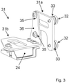
- the mower 12 has a holder 31 for the second inclination sensor 24, via which the second inclination sensor 24 can be detachably mounted on the guide rail 16 of the towing vehicle 11.
- the holder 31 for the second sensor 24 has a first section 31a and a second section 31b.
- the first section 31a is used for mounting on the guide rail 16 of the towing vehicle 11, and the second section 31b is used for accommodating the second inclination sensor 24.
- the holder 31 for the second inclination sensor 24 has magnets 32 and centering disks 33. In the exemplary embodiment shown, the magnets 32 and centering disks 33 act on the first section 31a of the holder 31 .
- the magnets 32 and centering discs 33 are intended for installation in a groove 34 in the guide rail 16 of the towing vehicle 11 (see 2 ) insertable, the magnets 32 holding the holder 31 and thus the second inclination sensor 24 on the guide rail 16, and the centering discs 33 are adapted to the width of the groove 34 in order to align the holder 31 exactly on the guide rail 16 and to prevent it from tilting as a result of play between the centering discs 33 and the groove 34 of the guide rail 16 .
- the second inclination sensor 34 can be mounted quickly and reliably on the towing vehicle 11, specifically in the same alignment that is always reproducible.
- the two sections or parts 31a and 31b of the holder 31 for the second inclination sensor 24 can be shifted and aligned relative to one another, for which slot holes 35 are used, which are formed on a tab 36 of the section 31b of the holder 31.
- the sections 31a and 31b of the bracket 31 can be aligned relative to one another.
- the holder 31 can advantageously be adapted to the available installation space on the towing vehicle 11 .
- the invention relates to the above-described control system for an agricultural tractor-trailer combination and to the above-described mower.
- the invention also relates to a tractor-trailer combination 10 consisting of the towing vehicle 11 and the attached mower 12, the agricultural tractor-trailer combination 10 having the control system described above and the mower 12 being designed as described above.
- the invention also relates to a method for calibrating the control system described above.
- first measured values of the two inclination sensors 23, 24 are determined in order to determine a first angle difference.
- Second measured values of the two inclination sensors 23, 24 are then determined in a second position of the combination 10 rotated or turned by 180° in relation to the first position of the combination 10 in order to determine a second angular difference.
- the train and trailer is in the same place as in the first position, but only turned or turned 180°.
- the control system can then be calibrated as a function of these two angle differences or the first and second measured values. Due to this calibration, it is not necessary for the tractor-trailer combination to stand on a level surface during the calibration. It is also not necessary for assemblies of the control system to be precisely aligned with one another during assembly.
Landscapes
- Life Sciences & Earth Sciences (AREA)
- Environmental Sciences (AREA)
- Engineering & Computer Science (AREA)
- Mechanical Engineering (AREA)
- Soil Sciences (AREA)
- Harvester Elements (AREA)
Abstract
mit einem zweiten Neigungssensor (24), der am Zugfahrzeug (11) montierbar ist und einen zweiten Neigungswinkel erfasst, mit einem Steuergerät (26), das den ersten Neigungswinkel vom ersten Neigungssensor (23) und den zweiten Neigungswinkel vom zweiten Neigungssensor (24) empfängt und abhängig von einer Ist-Winkeldifferenz zwischen dem ersten Neigungswinkel und dem zweiten Neigungswinkel eine Ist-Schnitthöhe des Mähwerks (12) ermittelt.
Description
- Die Erfindung betrifft ein Steuerungssystem für ein landwirtschaftliches Zuggespann aus einem Zugfahrzeug und einem Mähwerk. Des Weiteren betrifft die Erfindung ein Mähwerk und ein Zuggespann. Ferner betrifft die Erfindung ein Verfahren zum Kalibrieren eines Steuerungssystems.
- Aus der Praxis ist es hinlänglich bekannt, dass beim Mähen von Erntegut, wie zum Beispiel von Gras, an ein landwirtschaftliches Zugfahrzeug, insbesondere an einen Schlepper, ein Mähwerk angehängt wird. Ein Gespann aus einem landwirtschaftlichen Zugfahrzeug und einem Mähwerk wird auch als landwirtschaftliches Zuggespann bezeichnet. Um das zu mähende Erntegut mit hinreichender Qualität zu mähen, muss für Mähorgane des Mähwerks eine definierte Schnitthöhe eingestellt werden. Die Einstellung einer solchen definierten Schnitthöhe ist bislang aufwendig und fehleranfällig, da der Fahrer nach jeder Verstellung der Oberlenkerlänge absteigen und die Schnitthöhe messen muss, weil diese aus der Fahrerkabine des Zugfahrzeugs nicht einschätzbar ist. Insbesondere bereitet es dann Schwierigkeiten eine exakte definierte Schnitthöhe für die Mähorgane des Mähwerks einzustellen, wenn das landwirtschaftliche Zuggespann in einer Neigung, wie zum Beispiel an einer Steigung oder an einem Gefälle, betrieben wird. Es besteht Bedarf daran, eine Schnitthöhe für Mähorgane eines an ein landwirtschaftliches Zugfahrzeug angehängten Mähwerks insbesondere auch dann einfach und zuverlässig einzustellen, wenn das landwirtschaftliche Zuggespann in einer Neigung betrieben wird.
- Die
WO 2013/02661 A1 WO 2013/026661 A1 ist es bekannt, dass ein erster Winkelsensor am Zugfahrzeug und ein zweiter Winkelsensor am Grubber montiert ist. Beide Winkelsensoren stellen einem Steuergerät des Zugfahrzeugs Messwerte bereit. Abhängig von den Messwerten dieser Winkelsensoren kann eine Neigung des Grubbers oder des Zugfahrzeugs ermittelt werden. - Hiervon ausgehend liegt der vorliegenden Erfindung die Aufgabe zugrunde, ein neuartiges Steuerungssystem für ein landwirtschaftliches Zuggespann, bestehend aus einem Zugfahrzeug und einem Mähwerk, ein Verfahren zum Kalibrieren des Steuerungssystems, ein Mähwerk und ein Zuggespann zu schaffen.
- Diese Aufgabe wird durch ein Steuerungssystem nach Anspruch 1 gelöst.
- Erfindungsgemäß umfasst das Steuerungssystem einen ersten Neigungssensor, der am Mähwerk montierbar ist und einen ersten Neigungswinkel erfasst, einen zweiten Neigungssensor, der am Zugfahrzeug montierbar ist und einen zweiten Neigungswinkel erfasst, und ein Steuergerät, das den ersten Neigungswinkel vom ersten Neigungssensor und den zweiten Neigungswinkel vom zweiten Neigungssensor empfängt und abhängig von einer Ist-Winkeldifferenz zwischen dem ersten Neigungswinkel und dem zweiten Neigungswinkel eine Ist-Schnitthöhe des Mähwerks ermittelt. Mit der Erfindung wird erstmals vorgeschlagen, dass abhängig von den Neigungswinkeln, die mithilfe von zwei Neigungssensoren erfasst werden, eine Ist-Schnitthöhe des Mähwerks, nämlich von Mähorganen des Mähwerks, ermittelt wird, und zwar abhängig von der Ist-Winkeldifferenz der beiden erfassten Neigungswinkel. So kann einfach und zuverlässig die Ist-Schnitthöhe erfasst und angepasst werden. Dies ist insbesondere auch dann möglich, wenn das Zuggespann an einer Steigung oder einem Gefälle betrieben wird.
- Besonders bevorzugt ist das Steuergerät ein Teil des Mähwerks.
- Nach einer vorteilhaften Weiterbildung des Steuerungssystems ermittelt das Steuergerät eine Stellgröße, über welche das Mähwerk relativ zum Zugfahrzeug derart verlagerbar ist, dass die Ist-Winkeldifferenz einer Soll-Winkeldifferenz und damit die Ist-Schnitthöhe des Mähwerks einer Soll-Schnitthöhe des Mähwerks angepasst wird. So kann die Ist-Schnitthöhe einfach und zuverlässig sowie automatisiert an die Soll-Schnitthöhe des Mähwerks angepasst werden.
- Nach einer vorteilhaften Weiterbildung des Steuerungssystems ist der erste Neigungssensor Bestandteil des Mähwerks und am Mähwerk fest verbaut. Der zweite Neigungssensor ist Bestandteil des Mähwerks und am Zugfahrzeug lösbar montierbar, wobei der zweite Neigungssensor über ein Kabel an das Mähwerk angebunden und relativ zum Mähwerk zur Montage am Zugfahrzeug verlagerbar ist.
- Es ist besonders bevorzugt, wenn sowohl der erste Neigungssensor als auch der zweite Neigungssensor Bestandteil des Mähwerks sind. Der erste Neigungssensor ist fest am Mähwerk verbaut, der zweite Neigungssensor des Mähwerks ist über ein Kabel an das Mähwerk angebunden und kann am Kabel hängend relativ zum Mähwerk verlagert werden, um den zweiten Neigungssensor an das Zugfahrzeug zu montieren oder leicht lösbar am Zugfahrzeug anzubringen. Bei einem Anhängevorgang kann der zweite Neigungssensor schnell und komfortabel vom Fahrer am Zugfahrzeug montiert bzw. angebracht werden. Am Zugfahrzeug sind keine fest installierten Neigungssensoren erforderlich. Der Fahrer muss keine Steckverbindungen kuppeln. Derartige Steckverbindungen können schnell verschmutzen und sind störanfällig.
- Das Verfahren zum Kalibrieren des Steuerungssystems ist in Anspruch 4 definiert. Das Mähwerk ist in Anspruch 5 und das Zuggespann ist in Anspruch 9 oder Anspruch 10 definiert.
- Nach einer vorteilhaften Weiterbildung des Mähwerks weist dasselbe eine Halterung für den zweiten Neigungssensor auf, über welchen der zweite Neigungssensor an eine Führungsschiene der Anhängevorrichtung des Zugfahrzeugs lösbar montierbar ist. Vorzugsweise weist die Halterung Magnete und Zentrierungsscheiben auf, wobei die Magnete die Halterung an der Führungsschiene halten, und wobei die Zentrierungsscheiben in eine Nut der Führungsschiene eingreifen und an die Breite der Nut angepasst sind. Über eine solche Haltevorrichtung kann der zweite Neigungssensor, der Bestandteil des Mähwerks ist, schnell und zuverlässig am Zugfahrzeug montiert oder angebracht werden, und zwar in einer stets reproduzierbaren gleichen Ausrichtung.
- Bevorzugte Weiterbildungen der Erfindung ergeben sich aus den Unteransprüchen und der nachfolgenden Beschreibung. Ausführungsbeispiele der Erfindung werden, ohne hierauf beschränkt zu sein, an Hand der Zeichnung näher erläutert. Dabei zeigt:
- Fig. 1
- einen Ausschnitt aus einem landwirtschaftliches Zuggespann aus einem Zugfahrzeug und einem Mähwerk;
- Fig. 2
- ein Detail der
Fig. 1 in perspektivischer Ansicht.; - Fig. 3
- ein Detail der
Fig. 1 ,2 in perspektivischer Ansicht. -
Fig. 1 zeigt einen Ausschnitt aus einem landwirtschaftlichen Zuggespann 10, welches ein Zugfahrzeug 11 und ein an das Zugfahrzeug 11 angehängtes Mähwerk 12 umfasst. Vom Zugfahrzeug 11 sind ein Hinterrad 13, eine als Drei-Punkt-Kraftheber ausgebildete Anhängevorrichtung 14, ein Zugmaul 15 sowie eine Führungsschiene 16 gezeigt. Die als Drei-Punkt-Kraftheber ausgebildete Anhängevorrichtung 14 weist einen Oberlenker 17 sowie zwei Unterlenker 18 auf. Der Drei-Punkt-Kraftheber ist auch unter der Bezeichnung Drei-Punkt-Hydraulik bekannt. - Das Mähwerk 12 verfügt über ein Mähwerktraggestell 19, welches eine Ankoppelvorrichtung 20 zum Anhängen des Mähwerks 12 an die Anhängevorrichtung 14 des Zugfahrzeugs 11 aufweist. Mit einem ersten Abschnitt 20a dieser Ankoppelvorrichtung 20 ist das Mähwerk 12 an die Unterlenker 18 der Anhängevorrichtung 14 des Zugfahrzeugs 11 ankoppelbar. Mit einem zweiten Abschnitt 20b dieser Ankoppelvorrichtung 20 ist das Mähwerk 12 an den Oberlenker 17 der Anhängevorrichtung 14 des Zugfahrzeugs 11 ankoppelbar.
- Wie dem Pfeil I der
Fig. 1 entnommen werden kann, ist der Oberlenker 17 ein- und ausfahrbar, insbesondere teleskopierbar. Bei dem Ein- und Ausfahren des Oberlenkers 17 in Richtung des Pfeils I wird das Mähwerk 12 um eine Achse 21 gekippt oder geneigt, die zwischen dem ersten Abschnitt 20a der Ankoppelvorrichtung 20 und den Unterlenkern 18 der Anhängevorrichtung 14 ausgebildet ist. Hierbei wird das Mähwerk 12 im Sinne des Doppelpfeils II derFig. 1 gekippt oder geneigt. Wird der Oberlenker 17 weiter ausgefahren, so wird das Mähwerk 12 an seinem hinteren Ende nach unten geneigt. Dadurch dreht sich ein Messer 22a eines Mähorgans 22 nach oben, wodurch sich die Schnitthöhe X vergrößert. Wird der Oberlenker 17 weiter eingefahren also verkürzt, so wird das Mähwerk an seinem hinteren Ende nach oben geneigt also angehoben. Dadurch dreht sich das Messer 22a des Mähorgans 22 nach unten, wodurch sich die Schnitthöhe X verringert bzw. sich eine niedrigere Schnitthöhe einstellt. - Das Mähwerk 12 ist insbesondere ein Scheibenmähwerk.
- Um nun die Schnitthöhe X des Mähwerks 12 bzw. der Mähorgane 22 des Mähwerks 12 einfach und zuverlässig auch dann einstellen zu können, wenn das landwirtschaftliche Zuggespann 10 an einer Steigung oder einem Gefälle betrieben wird - also das Zuggespann 10 insbesondere hangaufwärts oder hangabwärts fährt - wird ein Steuerungssystem für das landwirtschaftliche Zuggespann 10 vorgeschlagen, ebenso ein Mähwerk, ein landwirtschaftliches Zuggespann sowie ein Verfahren zum Kalibrieren des Steuerungssystems.
- Das Steuerungssystem verfügt weiterhin über einen ersten Neigungssensor 23.
- Der erste Neigungssensor 23 ist am Mähwerk 12 montiert und erfasst einen ersten Neigungswinkel, nämlich einen Neigungswinkel des Mähwerks 12. Der erste Neigungssensor 23 ist Bestandteil des Mähwerks 12 und am Mähwerk 12 fest verbaut, insbesondere am Mähwerktraggestell 19.
- Das Steuerungssystem verfügt weiterhin über einen zweiten Neigungssensor 24.
- Der zweite Neigungssensor 24 ist am Zugfahrzeug 11 montierbar und erfasst einen zweiten Neigungswinkel. Der zweite Neigungssensor 24 ist vorzugsweise auch Bestandteil des Mähwerks 12 und am Zugfahrzeug 11 lösbar montierbar. Hierzu ist der zweite Neigungssensor 24, der Bestandteil des Mähwerks 12 ist, über ein Kabel 25 an das Mähwerk 12 angebunden und relativ zum Mähwerk 12 verlagerbar, um den zweiten Neigungssensor 24 am Zugfahrzeug 11 zu montieren oder anzubringen.
- Das Steuerungssystem verfügt neben den beiden Neigungssensoren 23 und 24 weiterhin über ein Steuergerät 26, welches am Mähwerk 12 angeordnet ist.
- Das Steuergerät 26 des Mähwerks 12 empfängt den ersten Neigungswinkel vom ersten Neigungssensor 23 und den zweiten Neigungswinkel vom zweiten Neigungssensor 25. Ein Pfeil 27 visualisiert als Eingangsgröße für das Steuergerät 26 den vom ersten Neigungssensor 23 erfassten ersten Neigungswinkel, ein Pfeil 28 visualisiert als weitere Eingangsgröße für das Steuergerät 26 den vom zweiten Neigungssensor 24 ermittelten zweiten Neigungswinkel. Das Steuergerät 26 ist datentechnisch mit den Neigungssensoren 23, 25 verbunden.
- Das Steuergerät 26 ermittelt abhängig von den beiden Neigungswinkeln der beiden Neigungssensoren 23, 24 eine Ist-Winkeldifferenz zwischen dem ersten Neigungswinkel des ersten Neigungssensors 23 und dem zweiten Neigungswinkel des zweiten Neigungssensors 24, wobei das Steuergerät 26 abhängig von dieser Ist-Winkeldifferenz und abhängig von der Geometrie des Mähwerks 12 eine Ist-Schnitthöhe, nämlich der Mähorgane 22 des Mähwerks 12, ermittelt. Das Steuergerät 26 kann die ermittelte Ist-Schnitthöhe als Ausgangsgröße 29 ausgeben und zum Beispiel über konventionelle Datenschnittstellen an ein Anzeige-Terminal ― beispielsweise ein ISO-Bus-Terminal ― übertragen, um einem Fahrer des Zugfahrzeugs 11 die Ist-Schnitthöhe darauf anzuzeigen.
- Weiterhin ist es möglich, dass das Steuergerät 26 die ermittelte Ist-Winkeldifferenz mit einer im Steuergerät 26 hinterlegten Soll-Winkeldifferenz und damit die Ist-Schnitthöhe des Mähwerks 12 mit einer Soll-Schnitthöhe desselben vergleicht, um abhängig hiervon eine Stellgröße, zum Beispiel für den Oberlenker 17 der Anhängevorrichtung 14 des Zugfahrzeugs 11, zu generieren, mithilfe derer der Oberlenker 17 derart ansteuerbar und das Mähwerk 12 derart relativ zum Zugfahrzeug 11 verlagerbar ist, dass die Ist-Winkeldifferenz der Soll-Winkeldifferenz und damit die Ist-Schnitthöhe des Mähwerks 12 der Soll-Schnitthöhe des Mähwerks 12 automatisch angepasst wird. Für eine automatische Anpassung - d.h. für die Ansteuerung des Oberlenkers 17 durch das Steuergerät 26 des Mähwerks kann das Steuergerät 26 mit einem entsprechenden Steuergerät des Zugfahrzeugs 11 gekoppelt oder datentechnisch verbunden werden. Es ist jedoch auch möglich den Oberlenker 17 an die Ölversorgung des Mähwerks anzuschließen. In diesem Fall kann das Steuergerät 26 des Mähwerks den Oberlenker 17 selbst direkt ansteuern und eine Kopplung bzw. datentechnische Verbindung zu einem Steuergerät des Zugfahrzeugs 11 wird nicht benötigt.
Fig. 1 und2 visualisieren eine derartige Stellgröße als weiterer Ausgangsgröße 30 des Steuergeräts 26. - Wie bereits ausgeführt, ist der erste Neigungssensor 23 fest, insbesondere am Mähwerktraggestell 19 des Mähwerks 12, verbaut, wohingegen der zweite Neigungssensor 24 über das Kabel 25 an das Mähwerk 12 angebunden ist und relativ zum Mähwerk 12 verlagert werden kann, um den zweiten Neigungssensor 24 lösbar am Zugfahrzeug 11 zu montieren.
- Im gezeigten, bevorzugten Ausführungsbeispiel verfügt das Mähwerk 12 über eine Halterung 31 für den zweiten Neigungssensor 24, über welche der zweite Neigungssensor 24 an der Führungsschiene 16 des Zugfahrzeugs 11 lösbar montiert werden kann. Die Halterung 31 für den zweiten Sensor 24 verfügt dabei im gezeigten Ausführungsbeispiel über einen ersten Abschnitt 31a und einen zweiten Abschnitt 31b. Der erste Abschnitt 31a dient im gezeigten Ausführungsbeispiel der Montage an der Führungsschiene 16 des Zugfahrzeugs 11, der zweite Abschnitt 31b dient der Aufnahme des zweiten Neigungssensors 24. Die Halterung 31 für den zweiten Neigungssensor 24 weist Magnete 32 und Zentrierscheiben 33 auf. Die Magnete 32 und Zentrierscheiben 33 greifen dabei im gezeigten Ausführungsbeispiel an dem ersten Abschnitt 31a der Halterung 31 an. Die Magnete 32 und Zentrierscheiben 33 sind zur Montage in eine Nut 34 der Führungsschiene 16 des Zugfahrzeugs 11 (siehe
Fig. 2 ) einführbar, wobei die Magnete 32 die Halterung 31 und damit den zweiten Neigungssensor 24 an der Führungsschiene 16 halten, und wobei die Zentrierungsscheiben 33 an die Breite der Nut 34 angepasst sind, um die Halterung 31 exakt an der Führungsschiene 16 auszurichten und ein Verkippen derselben infolge eines Spiels zwischen den Zentrierungsscheiben 33 und der Nut 34 der Führungsschiene 16 zu vermeiden. So kann der zweite Neigungssensor 34 schnell und zuverlässig am Zugfahrzeug 11 montiert werden, und zwar in einer stets reproduzierbaren, gleichen Ausrichtung. - Wie
Fig. 3 zeigt, können die beiden Abschnitte bzw. Teile 31a und 31b der Halterung 31 für den zweiten Neigungssensor 24 zueinander verlagert und ausgerichtet werden, wozu Langlöcher 35 dienen, die an einer Lasche 36 des Abschnitts 31b der Halterung 31 ausgebildet sind. Nach Lösen der sich durch diese Langlöcher 35 erstreckenden Befestigungsschrauben können die Abschnitte 31a und 31b der Halterung 31 relativ zueinander ausgerichtet werden. Dadurch kann die Halterung 31 vorteilhaft an den verfügbaren Bauraum am Zugfahrzeug 11 angepasst werden. - Statt der Führungsschiene 16 kann selbstverständlich auch ein anderer gleichbleibender Fixpunkt am Zugfahrzeug 11 zur Montage des zweiten Neigungssensors 34 vorgesehen werden.
- Die Erfindung betrifft das oben beschriebene Steuerungssystem eines landwirtschaftlichen Zuggespanns sowie das oben beschriebene Mähwerk.
- Ferner betrifft die Erfindung ein Zuggespann 10 bestehend aus dem Zugfahrzeug 11 und dem angehängten Mähwerk 12, wobei das landwirtschaftliche Zuggespann 10 das oben beschriebene Steuerungssystem aufweist und das Mähwerk 12 wie oben beschrieben ausgebildet ist.
- Ferner betrifft die Erfindung ein Verfahren zum Kalibrieren des oben beschriebenen Steuerungssystems. Hierzu werden in einer ersten Position des Zuggespanns 10 erste Messwerte der beiden Neigungssensoren 23, 24 ermittelt, um eine erste Winkeldifferenz zu bestimmen. Nachfolgend werden in einer gegenüber der ersten Position des Zuggespanns 10 um 180° gedrehten oder gewendeten zweiten Position des Zuggespanns 10 zweite Messwerte der beiden Neigungssensoren 23, 24 ermittelt, um eine zweite Winkeldifferenz zu bestimmen. In der zweiten Position befindet sich das Zuggespann an derselben Stelle wie in der ersten Position, jedoch lediglich um 180° gewendet oder gedreht. Abhängig von diesen beiden Winkeldifferenzen bzw. den ersten und zweiten Messwerten kann dann das Steuerungssystem kalibriert werden. Durch diese Kalibrierung ist es nicht nötig, dass bei der Kalibrierung das Zuggespann auf einem ebenen Untergrund stehen muss. Auch ist es nicht erforderlich, dass Baugruppen des Steuerungssystems bei der Montage exakt zueinander ausgerichtet werden müssen.
-
- 10
- Zuggespann
- 11
- Zugfahrzeug
- 12
- Mähwerk
- 13
- Hinterrad
- 14
- Anhängevorrichtung
- 15
- Zugmaul
- 16
- Führungsschiene
- 17
- Oberlenker
- 18
- Unterlenker
- 19
- Mähwerktraggestell
- 20
- Ankoppelverrichtung
- 20a
- Abschnitt
- 20b
- Abschnitt
- 21
- Drehachse
- 22
- Mähorgan
- 22a
- Messer
- 23
- Neigungssensor
- 24
- Neigungssensor
- 25
- Kabel
- 26
- Steuergerät
- 27
- Eingangsgröße
- 28
- Eingangsgröße
- 29
- Ausgangsgröße
- 30
- Ausgangsgröße
- 31
- Halterung
- 31a
- Abschnitt
- 31b
- Abschnitt
- 32
- Magnet
- 33
- Zentrierungsscheibe
- 34
- Nut
- 35
- Langloch
- 36
- Lasche
Claims (10)
- Steuerungssystem für ein landwirtschaftliches Zuggespann (10) bestehend aus einem Zugfahrzeug (11) und einem Mähwerk (12),mit einem ersten Neigungssensor (23), der am Mähwerk (12) montierbar ist und einen ersten Neigungswinkel erfasst,mit einem zweiten Neigungssensor (24), der am Zugfahrzeug (11) montierbar ist und einen zweiten Neigungswinkel erfasst,mit einem Steuergerät (26), das den ersten Neigungswinkel vom ersten Neigungssensor (23) und den zweiten Neigungswinkel vom zweiten Neigungssensor (24) empfängt und abhängig von einer Ist-Winkeldifferenz zwischen dem ersten Neigungswinkel und dem zweiten Neigungswinkel eine Ist-Schnitthöhe des Mähwerks (12) ermittelt.
- Steuerungssystem nach Anspruch 1, dadurch gekennzeichnet, dass das Steuergerät (26) eine Stellgröße ermittelt, über welche das Mähwerk (12) derart relativ zum Zugfahrzeug (11) verlagerbar ist, dass die Ist-Winkeldifferenz einer Soll-Winkeldifferenz und damit die Ist-Schnitthöhe des Mähwerks (12) einer Soll-Schnitthöhe des Mähwerks (12) angepasst wird.
- Steuerungssystem nach Anspruch 1 oder 2, dadurch gekennzeichnet, dassder erste Neigungssensor (23) am Mähwerk (12) fest verbaut ist,der zweite Neigungssensor (24) am Zugfahrzeug (11) lösbar montierbar ist, wobei der zweite Neigungssensor (24) über ein Kabel (25) an das Mähwerk (12) angebunden und relativ zum Mähwerk (12) zur Montage am Zugfahrzeug (11) verlagerbar ist.
- Verfahren zum Kalibrieren eines Steuerungssystems nach einem der Ansprüche 1 bis 3, dadurch gekennzeichnet, dassin einer ersten Position des Zuggespanns (10) erste Messwerte der beiden Neigungssensoren (23, 24) ermittelt werden;in einer gegenüber der ersten Position des Zuggespanns (10) um 180° gedrehten oder gewendeten zweiten Position des Zuggespanns (10) zweite Messwerte der beiden Neigungssensoren (23, 24) ermittelt werden;abhängig von den ersten und zweiten Messwerten das Steuerungssystem kalibriert wird.
- Mähwerk (12),mit einem Mähwerktraggestell (19), welches ein Ankoppelvorrichtung (20) zum Anhängen des Mähwerks (12) an eine Anhängevorrichtung (14) eines Zugfahrzeugs (11) aufweist,mit mehreren am Mähwerktraggestell (19) aufgenommenen Mähorganen (22),mit einem ersten Neigungssensor (23), der am Mähwerktraggestell (19) fest verbaut ist,mit einem zweiten Neigungssensor (24), der am Zugfahrzeug (11) lösbar montierbar ist, wobei der zweite Neigungssensor (24) relativ zum Mähwerktraggestell (19) zur Montage am Zugfahrzeug (11) verlagerbar ist undmit einem Steuergerät (26), welches datentechnisch mit den Neigungssensoren (23, 25) verbunden ist.
- Mähwerk nach Anspruch 5, gekennzeichnet durch
eine Halterung (31) für den zweiten Neigungssensor (24), über welche der zweite Neigungssensor (24) an eine Führungsschiene (16) des Zugfahrzeugs (11) lösbar montierbar ist. - Mähwerk nach Anspruch 6, dadurch gekennzeichnet, dassdie Halterung (31) Magnete (32) und Zentrierungsscheiben (33) aufweist,die Magnete (32) die Halterung (31) an der Führungsschiene (16) halten,die Zentrierungsscheiben (33) in eine Nut (34) der Führungsschiene (14) eingreifen und an die Breite der Nut (34) angepasst sind.
- Mähwerk nach Anspruch 7, dadurch gekennzeichnet, dassdie Halterung (31) einen Abschnitt (31b) zur Aufnahme des zweiten Neigungssensor (24) aufweist,die Halterung (31) einen weiteren Abschnitt (31a) zur Aufnahme der Magnete (32) und Zentrierungsscheiben (33) aufweist,die beiden Abschnitte (31a, 31b) relativ zueinander ausrichtbar sind.
- Landwirtschaftliches Zuggespann (10), mit einem insbesondere als Schlepper ausgebildeten landwirtschaftlichen Zugfahrzeug (11) und einem an das Zugfahrzeug (11) angehängten Mähwerk (12), gekennzeichnet durch ein Steuerungssystem nach einem der Ansprüche 1 bis 3.
- Landwirtschaftliches Zuggespann (10), mit einem insbesondere als Schlepper ausgebildeten landwirtschaftlichen Zugfahrzeug (11) und einem an das Zugfahrzeug (11) angehängten Mähwerk (12), insbesondere Zuggespann (10) nach Anspruch 9, dadurch gekennzeichnet, dass das Mähwerk nach einem der Ansprüche 5 bis 8 ausgebildet ist.
Priority Applications (1)
| Application Number | Priority Date | Filing Date | Title |
|---|---|---|---|
| SI202130184T SI3944751T1 (sl) | 2020-07-29 | 2021-07-20 | Krmilni sistem za kmetijsko vlečno garnituro iz vlečnega vozila in kosilnice, kosilnica in vlečna garnitura |
Applications Claiming Priority (1)
| Application Number | Priority Date | Filing Date | Title |
|---|---|---|---|
| DE102020119957.0A DE102020119957A1 (de) | 2020-07-29 | 2020-07-29 | Steuerungssystem für ein landwirtschaftliches Zuggespann aus einem Zugfahrzeug und einem Mähwerk, Mähwerk und Zuggespann |
Publications (2)
| Publication Number | Publication Date |
|---|---|
| EP3944751A1 true EP3944751A1 (de) | 2022-02-02 |
| EP3944751B1 EP3944751B1 (de) | 2024-06-26 |
Family
ID=76999680
Family Applications (1)
| Application Number | Title | Priority Date | Filing Date |
|---|---|---|---|
| EP21186612.4A Active EP3944751B1 (de) | 2020-07-29 | 2021-07-20 | Steuerungssystem für ein landwirtschaftliches zuggespann aus einem zugfahrzeug und einem mähwerk, mähwerk und zuggespann |
Country Status (5)
| Country | Link |
|---|---|
| EP (1) | EP3944751B1 (de) |
| DE (1) | DE102020119957A1 (de) |
| DK (1) | DK3944751T3 (de) |
| PL (1) | PL3944751T3 (de) |
| SI (1) | SI3944751T1 (de) |
Families Citing this family (2)
| Publication number | Priority date | Publication date | Assignee | Title |
|---|---|---|---|---|
| DE102023105019A1 (de) | 2023-03-01 | 2024-09-05 | Claas Saulgau Gmbh | Landwirtschaftliches Fahrzeuggespann zum Mähen von Futtererntegut |
| DE102023104985A1 (de) | 2023-03-01 | 2024-09-05 | Claas Saulgau Gmbh | Landwirtschaftliches Fahrzeuggespann zum Mähen von Futtererntegut |
Citations (6)
| Publication number | Priority date | Publication date | Assignee | Title |
|---|---|---|---|---|
| DE10140383A1 (de) * | 2001-08-23 | 2003-03-13 | Rau Serta Hydraulik Gmbh | Steuerung oder Regelung der Lage eines an einem Schlepper angebauten Anbaugerätes |
| DE10227484A1 (de) * | 2002-06-19 | 2004-02-26 | Claas Selbstfahrende Erntemaschinen Gmbh | Vorrichtung und Verfahren zur Lagesteuerung eines Erntegutaufnahmegerätes landwirtschaftlicher Erntemaschinen |
| WO2013002661A1 (en) | 2011-06-29 | 2013-01-03 | Musat-Marcu Sorin | Matrix for receiving a tissue sample and use thereof |
| WO2013026661A1 (en) | 2011-08-23 | 2013-02-28 | Agco Sa | Agricultural tractor linkage control system |
| EP3311641A1 (de) * | 2016-10-19 | 2018-04-25 | Robert Bosch GmbH | Steuervorrichtung für eine zugmaschine, zugmaschine mit einer steuervorrichtung und verfahren zum steuern einer zugmaschine |
| US20200128717A1 (en) * | 2018-10-31 | 2020-04-30 | Deere & Company | Windrower header sensing and control method |
-
2020
- 2020-07-29 DE DE102020119957.0A patent/DE102020119957A1/de not_active Withdrawn
-
2021
- 2021-07-20 DK DK21186612.4T patent/DK3944751T3/da active
- 2021-07-20 SI SI202130184T patent/SI3944751T1/sl unknown
- 2021-07-20 PL PL21186612.4T patent/PL3944751T3/pl unknown
- 2021-07-20 EP EP21186612.4A patent/EP3944751B1/de active Active
Patent Citations (6)
| Publication number | Priority date | Publication date | Assignee | Title |
|---|---|---|---|---|
| DE10140383A1 (de) * | 2001-08-23 | 2003-03-13 | Rau Serta Hydraulik Gmbh | Steuerung oder Regelung der Lage eines an einem Schlepper angebauten Anbaugerätes |
| DE10227484A1 (de) * | 2002-06-19 | 2004-02-26 | Claas Selbstfahrende Erntemaschinen Gmbh | Vorrichtung und Verfahren zur Lagesteuerung eines Erntegutaufnahmegerätes landwirtschaftlicher Erntemaschinen |
| WO2013002661A1 (en) | 2011-06-29 | 2013-01-03 | Musat-Marcu Sorin | Matrix for receiving a tissue sample and use thereof |
| WO2013026661A1 (en) | 2011-08-23 | 2013-02-28 | Agco Sa | Agricultural tractor linkage control system |
| EP3311641A1 (de) * | 2016-10-19 | 2018-04-25 | Robert Bosch GmbH | Steuervorrichtung für eine zugmaschine, zugmaschine mit einer steuervorrichtung und verfahren zum steuern einer zugmaschine |
| US20200128717A1 (en) * | 2018-10-31 | 2020-04-30 | Deere & Company | Windrower header sensing and control method |
Also Published As
| Publication number | Publication date |
|---|---|
| DE102020119957A1 (de) | 2022-02-03 |
| EP3944751B1 (de) | 2024-06-26 |
| PL3944751T3 (pl) | 2024-11-04 |
| DK3944751T3 (da) | 2024-08-26 |
| SI3944751T1 (sl) | 2024-10-30 |
Similar Documents
| Publication | Publication Date | Title |
|---|---|---|
| EP2283719B1 (de) | Anordnung zur seitlichen verstellbaren Anbringung eines landwirtschaftlichen Arbeitsgeräts an einem Fahrzeug | |
| DE102019121322A1 (de) | Hackvorrichtung | |
| WO2016041547A1 (de) | Zugfahrzeug und anhängevorrichtung für ein anbaugerät | |
| DE10247273C1 (de) | Vorrichtung zum Regeln der Position eines Anbaugeräts relativ zu einem Trägerfahrzeug | |
| DE10311796A1 (de) | Aussaatelement | |
| EP3944751B1 (de) | Steuerungssystem für ein landwirtschaftliches zuggespann aus einem zugfahrzeug und einem mähwerk, mähwerk und zuggespann | |
| EP1205097A1 (de) | Selbstnivellierender Zusammenbau von Gabelkopf und Zugvorrichtung | |
| EP0533041A1 (de) | Führungsvorrichtung für Unterlänker und landwirtschaftliches Fahrzeug | |
| EP0063167B1 (de) | Land- und/oder bauwirtschaftlich nutzbares Kraftfahrzeug mit frontseitiger Geräteanbauvorrichtung | |
| EP0036203B1 (de) | Zugwiderstandsregelung für Traktoren | |
| WO2016192973A1 (de) | Steueranordnung für eine zugmaschine, zugmaschine mit einer steueranordnung und verfahren für eine steueranordnung | |
| DE3105639A1 (de) | "geraetekombination fuer die landwirtschaft" | |
| DE3316128A1 (de) | Anhaengevorrichtung fuer landwirtschaftliche schlepperfahrzeuge | |
| DE102017214354B3 (de) | Landwirtschaftliches Arbeitsfahrzeug mit Bodeneingriffsmitteln zur Übertragung von Querkräften | |
| EP3351074A1 (de) | Anbauvorrichtung eines anbaugeräts, anbaugerät und gespann aus einem anbaugerät und einem fahrzeug | |
| EP3387891B1 (de) | Zugvorrichtung | |
| AT403753B (de) | Tragrahmen mit landwirtschaftlicher erntemaschine, insbesondere rotationsmähwerk | |
| DE102018123958A1 (de) | Dreipunktkupplung | |
| DE2436853B2 (de) | Mehrschariger Aufsattelpflug, insbesondere Beetpflug | |
| DE1480701C3 (de) | Kupplungsvorrichtung für Anhänger von Kraftfahrzeugen, insbesondere Schleppern | |
| EP3818797B1 (de) | Landwirtschaftliches arbeitsgerät und -gerätekombination | |
| EP4074157B1 (de) | Landwirtschaftliche maschine mit zumindest einem ausleger | |
| EP0105055A1 (de) | Transportwagen zur Aufnahme einer Erntebergungsvorrichtung | |
| DE3408453C2 (de) | Aufhängeeinrichtung einer Güllerührwelle an einem Traktor | |
| EP0400366A1 (de) | Von einem Schlepper ziehbare Anordnung von Hacken |
Legal Events
| Date | Code | Title | Description |
|---|---|---|---|
| PUAI | Public reference made under article 153(3) epc to a published international application that has entered the european phase |
Free format text: ORIGINAL CODE: 0009012 |
|
| STAA | Information on the status of an ep patent application or granted ep patent |
Free format text: STATUS: THE APPLICATION HAS BEEN PUBLISHED |
|
| AK | Designated contracting states |
Kind code of ref document: A1 Designated state(s): AL AT BE BG CH CY CZ DE DK EE ES FI FR GB GR HR HU IE IS IT LI LT LU LV MC MK MT NL NO PL PT RO RS SE SI SK SM TR |
|
| STAA | Information on the status of an ep patent application or granted ep patent |
Free format text: STATUS: REQUEST FOR EXAMINATION WAS MADE |
|
| 17P | Request for examination filed |
Effective date: 20220802 |
|
| RBV | Designated contracting states (corrected) |
Designated state(s): AL AT BE BG CH CY CZ DE DK EE ES FI FR GB GR HR HU IE IS IT LI LT LU LV MC MK MT NL NO PL PT RO RS SE SI SK SM TR |
|
| P01 | Opt-out of the competence of the unified patent court (upc) registered |
Effective date: 20230712 |
|
| GRAP | Despatch of communication of intention to grant a patent |
Free format text: ORIGINAL CODE: EPIDOSNIGR1 |
|
| STAA | Information on the status of an ep patent application or granted ep patent |
Free format text: STATUS: GRANT OF PATENT IS INTENDED |
|
| INTG | Intention to grant announced |
Effective date: 20240229 |
|
| GRAS | Grant fee paid |
Free format text: ORIGINAL CODE: EPIDOSNIGR3 |
|
| GRAA | (expected) grant |
Free format text: ORIGINAL CODE: 0009210 |
|
| STAA | Information on the status of an ep patent application or granted ep patent |
Free format text: STATUS: THE PATENT HAS BEEN GRANTED |
|
| AK | Designated contracting states |
Kind code of ref document: B1 Designated state(s): AL AT BE BG CH CY CZ DE DK EE ES FI FR GB GR HR HU IE IS IT LI LT LU LV MC MK MT NL NO PL PT RO RS SE SI SK SM TR |
|
| REG | Reference to a national code |
Ref country code: GB Ref legal event code: FG4D Free format text: NOT ENGLISH |
|
| REG | Reference to a national code |
Ref country code: CH Ref legal event code: EP |
|
| REG | Reference to a national code |
Ref country code: DE Ref legal event code: R096 Ref document number: 502021004091 Country of ref document: DE |
|
| REG | Reference to a national code |
Ref country code: DK Ref legal event code: T3 Effective date: 20240819 |
|
| PG25 | Lapsed in a contracting state [announced via postgrant information from national office to epo] |
Ref country code: BG Free format text: LAPSE BECAUSE OF FAILURE TO SUBMIT A TRANSLATION OF THE DESCRIPTION OR TO PAY THE FEE WITHIN THE PRESCRIBED TIME-LIMIT Effective date: 20240626 |
|
| PG25 | Lapsed in a contracting state [announced via postgrant information from national office to epo] |
Ref country code: FI Free format text: LAPSE BECAUSE OF FAILURE TO SUBMIT A TRANSLATION OF THE DESCRIPTION OR TO PAY THE FEE WITHIN THE PRESCRIBED TIME-LIMIT Effective date: 20240626 Ref country code: HR Free format text: LAPSE BECAUSE OF FAILURE TO SUBMIT A TRANSLATION OF THE DESCRIPTION OR TO PAY THE FEE WITHIN THE PRESCRIBED TIME-LIMIT Effective date: 20240626 |
|
| REG | Reference to a national code |
Ref country code: LT Ref legal event code: MG9D |
|
| PG25 | Lapsed in a contracting state [announced via postgrant information from national office to epo] |
Ref country code: GR Free format text: LAPSE BECAUSE OF FAILURE TO SUBMIT A TRANSLATION OF THE DESCRIPTION OR TO PAY THE FEE WITHIN THE PRESCRIBED TIME-LIMIT Effective date: 20240927 |
|
| PG25 | Lapsed in a contracting state [announced via postgrant information from national office to epo] |
Ref country code: LV Free format text: LAPSE BECAUSE OF FAILURE TO SUBMIT A TRANSLATION OF THE DESCRIPTION OR TO PAY THE FEE WITHIN THE PRESCRIBED TIME-LIMIT Effective date: 20240626 |
|
| REG | Reference to a national code |
Ref country code: NL Ref legal event code: MP Effective date: 20240626 |
|
| PG25 | Lapsed in a contracting state [announced via postgrant information from national office to epo] |
Ref country code: NO Free format text: LAPSE BECAUSE OF FAILURE TO SUBMIT A TRANSLATION OF THE DESCRIPTION OR TO PAY THE FEE WITHIN THE PRESCRIBED TIME-LIMIT Effective date: 20240926 Ref country code: LV Free format text: LAPSE BECAUSE OF FAILURE TO SUBMIT A TRANSLATION OF THE DESCRIPTION OR TO PAY THE FEE WITHIN THE PRESCRIBED TIME-LIMIT Effective date: 20240626 Ref country code: HR Free format text: LAPSE BECAUSE OF FAILURE TO SUBMIT A TRANSLATION OF THE DESCRIPTION OR TO PAY THE FEE WITHIN THE PRESCRIBED TIME-LIMIT Effective date: 20240626 Ref country code: GR Free format text: LAPSE BECAUSE OF FAILURE TO SUBMIT A TRANSLATION OF THE DESCRIPTION OR TO PAY THE FEE WITHIN THE PRESCRIBED TIME-LIMIT Effective date: 20240927 Ref country code: FI Free format text: LAPSE BECAUSE OF FAILURE TO SUBMIT A TRANSLATION OF THE DESCRIPTION OR TO PAY THE FEE WITHIN THE PRESCRIBED TIME-LIMIT Effective date: 20240626 Ref country code: BG Free format text: LAPSE BECAUSE OF FAILURE TO SUBMIT A TRANSLATION OF THE DESCRIPTION OR TO PAY THE FEE WITHIN THE PRESCRIBED TIME-LIMIT Effective date: 20240626 Ref country code: RS Free format text: LAPSE BECAUSE OF FAILURE TO SUBMIT A TRANSLATION OF THE DESCRIPTION OR TO PAY THE FEE WITHIN THE PRESCRIBED TIME-LIMIT Effective date: 20240926 |
|
| PG25 | Lapsed in a contracting state [announced via postgrant information from national office to epo] |
Ref country code: NL Free format text: LAPSE BECAUSE OF FAILURE TO SUBMIT A TRANSLATION OF THE DESCRIPTION OR TO PAY THE FEE WITHIN THE PRESCRIBED TIME-LIMIT Effective date: 20240626 |
|
| PG25 | Lapsed in a contracting state [announced via postgrant information from national office to epo] |
Ref country code: NL Free format text: LAPSE BECAUSE OF FAILURE TO SUBMIT A TRANSLATION OF THE DESCRIPTION OR TO PAY THE FEE WITHIN THE PRESCRIBED TIME-LIMIT Effective date: 20240626 |
|
| PG25 | Lapsed in a contracting state [announced via postgrant information from national office to epo] |
Ref country code: PT Free format text: LAPSE BECAUSE OF FAILURE TO SUBMIT A TRANSLATION OF THE DESCRIPTION OR TO PAY THE FEE WITHIN THE PRESCRIBED TIME-LIMIT Effective date: 20241028 |
|
| PG25 | Lapsed in a contracting state [announced via postgrant information from national office to epo] |
Ref country code: PT Free format text: LAPSE BECAUSE OF FAILURE TO SUBMIT A TRANSLATION OF THE DESCRIPTION OR TO PAY THE FEE WITHIN THE PRESCRIBED TIME-LIMIT Effective date: 20241028 |
|
| PG25 | Lapsed in a contracting state [announced via postgrant information from national office to epo] |
Ref country code: EE Free format text: LAPSE BECAUSE OF FAILURE TO SUBMIT A TRANSLATION OF THE DESCRIPTION OR TO PAY THE FEE WITHIN THE PRESCRIBED TIME-LIMIT Effective date: 20240626 |
|
| PG25 | Lapsed in a contracting state [announced via postgrant information from national office to epo] |
Ref country code: IS Free format text: LAPSE BECAUSE OF FAILURE TO SUBMIT A TRANSLATION OF THE DESCRIPTION OR TO PAY THE FEE WITHIN THE PRESCRIBED TIME-LIMIT Effective date: 20241026 |
|
| PG25 | Lapsed in a contracting state [announced via postgrant information from national office to epo] |
Ref country code: CZ Free format text: LAPSE BECAUSE OF FAILURE TO SUBMIT A TRANSLATION OF THE DESCRIPTION OR TO PAY THE FEE WITHIN THE PRESCRIBED TIME-LIMIT Effective date: 20240626 |
|
| PG25 | Lapsed in a contracting state [announced via postgrant information from national office to epo] |
Ref country code: RO Free format text: LAPSE BECAUSE OF FAILURE TO SUBMIT A TRANSLATION OF THE DESCRIPTION OR TO PAY THE FEE WITHIN THE PRESCRIBED TIME-LIMIT Effective date: 20240626 Ref country code: SK Free format text: LAPSE BECAUSE OF FAILURE TO SUBMIT A TRANSLATION OF THE DESCRIPTION OR TO PAY THE FEE WITHIN THE PRESCRIBED TIME-LIMIT Effective date: 20240626 |
|
| PG25 | Lapsed in a contracting state [announced via postgrant information from national office to epo] |
Ref country code: SM Free format text: LAPSE BECAUSE OF FAILURE TO SUBMIT A TRANSLATION OF THE DESCRIPTION OR TO PAY THE FEE WITHIN THE PRESCRIBED TIME-LIMIT Effective date: 20240626 Ref country code: ES Free format text: LAPSE BECAUSE OF FAILURE TO SUBMIT A TRANSLATION OF THE DESCRIPTION OR TO PAY THE FEE WITHIN THE PRESCRIBED TIME-LIMIT Effective date: 20240626 |
|
| PG25 | Lapsed in a contracting state [announced via postgrant information from national office to epo] |
Ref country code: SM Free format text: LAPSE BECAUSE OF FAILURE TO SUBMIT A TRANSLATION OF THE DESCRIPTION OR TO PAY THE FEE WITHIN THE PRESCRIBED TIME-LIMIT Effective date: 20240626 Ref country code: SK Free format text: LAPSE BECAUSE OF FAILURE TO SUBMIT A TRANSLATION OF THE DESCRIPTION OR TO PAY THE FEE WITHIN THE PRESCRIBED TIME-LIMIT Effective date: 20240626 Ref country code: RO Free format text: LAPSE BECAUSE OF FAILURE TO SUBMIT A TRANSLATION OF THE DESCRIPTION OR TO PAY THE FEE WITHIN THE PRESCRIBED TIME-LIMIT Effective date: 20240626 Ref country code: IS Free format text: LAPSE BECAUSE OF FAILURE TO SUBMIT A TRANSLATION OF THE DESCRIPTION OR TO PAY THE FEE WITHIN THE PRESCRIBED TIME-LIMIT Effective date: 20241026 Ref country code: ES Free format text: LAPSE BECAUSE OF FAILURE TO SUBMIT A TRANSLATION OF THE DESCRIPTION OR TO PAY THE FEE WITHIN THE PRESCRIBED TIME-LIMIT Effective date: 20240626 Ref country code: EE Free format text: LAPSE BECAUSE OF FAILURE TO SUBMIT A TRANSLATION OF THE DESCRIPTION OR TO PAY THE FEE WITHIN THE PRESCRIBED TIME-LIMIT Effective date: 20240626 Ref country code: CZ Free format text: LAPSE BECAUSE OF FAILURE TO SUBMIT A TRANSLATION OF THE DESCRIPTION OR TO PAY THE FEE WITHIN THE PRESCRIBED TIME-LIMIT Effective date: 20240626 |
|
| PG25 | Lapsed in a contracting state [announced via postgrant information from national office to epo] |
Ref country code: IT Free format text: LAPSE BECAUSE OF FAILURE TO SUBMIT A TRANSLATION OF THE DESCRIPTION OR TO PAY THE FEE WITHIN THE PRESCRIBED TIME-LIMIT Effective date: 20240626 |
|
| REG | Reference to a national code |
Ref country code: CH Ref legal event code: PL |
|
| PG25 | Lapsed in a contracting state [announced via postgrant information from national office to epo] |
Ref country code: LU Free format text: LAPSE BECAUSE OF NON-PAYMENT OF DUE FEES Effective date: 20240720 |
|
| PG25 | Lapsed in a contracting state [announced via postgrant information from national office to epo] |
Ref country code: MC Free format text: LAPSE BECAUSE OF FAILURE TO SUBMIT A TRANSLATION OF THE DESCRIPTION OR TO PAY THE FEE WITHIN THE PRESCRIBED TIME-LIMIT Effective date: 20240626 |
|
| REG | Reference to a national code |
Ref country code: DE Ref legal event code: R097 Ref document number: 502021004091 Country of ref document: DE |
|
| PG25 | Lapsed in a contracting state [announced via postgrant information from national office to epo] |
Ref country code: MC Free format text: LAPSE BECAUSE OF FAILURE TO SUBMIT A TRANSLATION OF THE DESCRIPTION OR TO PAY THE FEE WITHIN THE PRESCRIBED TIME-LIMIT Effective date: 20240626 Ref country code: LU Free format text: LAPSE BECAUSE OF NON-PAYMENT OF DUE FEES Effective date: 20240720 |
|
| PG25 | Lapsed in a contracting state [announced via postgrant information from national office to epo] |
Ref country code: BE Free format text: LAPSE BECAUSE OF NON-PAYMENT OF DUE FEES Effective date: 20240731 Ref country code: CH Free format text: LAPSE BECAUSE OF NON-PAYMENT OF DUE FEES Effective date: 20240731 |
|
| PLBE | No opposition filed within time limit |
Free format text: ORIGINAL CODE: 0009261 |
|
| STAA | Information on the status of an ep patent application or granted ep patent |
Free format text: STATUS: NO OPPOSITION FILED WITHIN TIME LIMIT |
|
| 26N | No opposition filed |
Effective date: 20250327 |
|
| REG | Reference to a national code |
Ref country code: BE Ref legal event code: MM Effective date: 20240731 |
|
| PGFP | Annual fee paid to national office [announced via postgrant information from national office to epo] |
Ref country code: SI Payment date: 20250710 Year of fee payment: 5 |
|
| PG25 | Lapsed in a contracting state [announced via postgrant information from national office to epo] |
Ref country code: SE Free format text: LAPSE BECAUSE OF FAILURE TO SUBMIT A TRANSLATION OF THE DESCRIPTION OR TO PAY THE FEE WITHIN THE PRESCRIBED TIME-LIMIT Effective date: 20240626 |
|
| PGFP | Annual fee paid to national office [announced via postgrant information from national office to epo] |
Ref country code: DK Payment date: 20250725 Year of fee payment: 5 Ref country code: DE Payment date: 20250722 Year of fee payment: 5 |
|
| PGFP | Annual fee paid to national office [announced via postgrant information from national office to epo] |
Ref country code: PL Payment date: 20250711 Year of fee payment: 5 |
|
| PGFP | Annual fee paid to national office [announced via postgrant information from national office to epo] |
Ref country code: GB Payment date: 20250722 Year of fee payment: 5 |
|
| PGFP | Annual fee paid to national office [announced via postgrant information from national office to epo] |
Ref country code: AT Payment date: 20251020 Year of fee payment: 5 Ref country code: FR Payment date: 20250725 Year of fee payment: 5 |
|
| PGFP | Annual fee paid to national office [announced via postgrant information from national office to epo] |
Ref country code: IE Payment date: 20250723 Year of fee payment: 5 |
|
| PG25 | Lapsed in a contracting state [announced via postgrant information from national office to epo] |
Ref country code: CY Free format text: LAPSE BECAUSE OF FAILURE TO SUBMIT A TRANSLATION OF THE DESCRIPTION OR TO PAY THE FEE WITHIN THE PRESCRIBED TIME-LIMIT; INVALID AB INITIO Effective date: 20210720 |
|
| PG25 | Lapsed in a contracting state [announced via postgrant information from national office to epo] |
Ref country code: HU Free format text: LAPSE BECAUSE OF FAILURE TO SUBMIT A TRANSLATION OF THE DESCRIPTION OR TO PAY THE FEE WITHIN THE PRESCRIBED TIME-LIMIT; INVALID AB INITIO Effective date: 20210720 |
|
| PG25 | Lapsed in a contracting state [announced via postgrant information from national office to epo] |
Ref country code: TR Free format text: LAPSE BECAUSE OF FAILURE TO SUBMIT A TRANSLATION OF THE DESCRIPTION OR TO PAY THE FEE WITHIN THE PRESCRIBED TIME-LIMIT Effective date: 20240626 |
|
| PG25 | Lapsed in a contracting state [announced via postgrant information from national office to epo] |
Ref country code: LT Free format text: LAPSE BECAUSE OF FAILURE TO SUBMIT A TRANSLATION OF THE DESCRIPTION OR TO PAY THE FEE WITHIN THE PRESCRIBED TIME-LIMIT Effective date: 20240626 |