EP3942136B1 - Kühlgerät mit einstellbarer scharnieranordnung - Google Patents
Kühlgerät mit einstellbarer scharnieranordnung Download PDFInfo
- Publication number
- EP3942136B1 EP3942136B1 EP20708447.6A EP20708447A EP3942136B1 EP 3942136 B1 EP3942136 B1 EP 3942136B1 EP 20708447 A EP20708447 A EP 20708447A EP 3942136 B1 EP3942136 B1 EP 3942136B1
- Authority
- EP
- European Patent Office
- Prior art keywords
- adjustment mechanism
- housing
- door
- screw
- hinge assembly
- Prior art date
- Legal status (The legal status is an assumption and is not a legal conclusion. Google has not performed a legal analysis and makes no representation as to the accuracy of the status listed.)
- Active
Links
Images


Classifications
-
- E—FIXED CONSTRUCTIONS
- E05—LOCKS; KEYS; WINDOW OR DOOR FITTINGS; SAFES
- E05D—HINGES OR SUSPENSION DEVICES FOR DOORS, WINDOWS OR WINGS
- E05D7/00—Hinges or pivots of special construction
- E05D7/04—Hinges adjustable relative to the wing or the frame
- E05D7/0415—Hinges adjustable relative to the wing or the frame with adjusting drive means
- E05D7/0423—Screw-and-nut mechanisms
-
- E—FIXED CONSTRUCTIONS
- E05—LOCKS; KEYS; WINDOW OR DOOR FITTINGS; SAFES
- E05D—HINGES OR SUSPENSION DEVICES FOR DOORS, WINDOWS OR WINGS
- E05D3/00—Hinges with pins
- E05D3/02—Hinges with pins with one pin
-
- E—FIXED CONSTRUCTIONS
- E05—LOCKS; KEYS; WINDOW OR DOOR FITTINGS; SAFES
- E05D—HINGES OR SUSPENSION DEVICES FOR DOORS, WINDOWS OR WINGS
- E05D7/00—Hinges or pivots of special construction
- E05D7/08—Hinges or pivots of special construction for use in suspensions comprising two spigots placed at opposite edges of the wing, especially at the top and the bottom, e.g. trunnions
- E05D7/081—Hinges or pivots of special construction for use in suspensions comprising two spigots placed at opposite edges of the wing, especially at the top and the bottom, e.g. trunnions the pivot axis of the wing being situated near one edge of the wing, especially at the top and bottom, e.g. trunnions
-
- E—FIXED CONSTRUCTIONS
- E05—LOCKS; KEYS; WINDOW OR DOOR FITTINGS; SAFES
- E05Y—INDEXING SCHEME ASSOCIATED WITH SUBCLASSES E05D AND E05F, RELATING TO CONSTRUCTION ELEMENTS, ELECTRIC CONTROL, POWER SUPPLY, POWER SIGNAL OR TRANSMISSION, USER INTERFACES, MOUNTING OR COUPLING, DETAILS, ACCESSORIES, AUXILIARY OPERATIONS NOT OTHERWISE PROVIDED FOR, APPLICATION THEREOF
- E05Y2800/00—Details, accessories and auxiliary operations not otherwise provided for
- E05Y2800/26—Form or shape
- E05Y2800/30—Form or shape inclined, angled
-
- E—FIXED CONSTRUCTIONS
- E05—LOCKS; KEYS; WINDOW OR DOOR FITTINGS; SAFES
- E05Y—INDEXING SCHEME ASSOCIATED WITH SUBCLASSES E05D AND E05F, RELATING TO CONSTRUCTION ELEMENTS, ELECTRIC CONTROL, POWER SUPPLY, POWER SIGNAL OR TRANSMISSION, USER INTERFACES, MOUNTING OR COUPLING, DETAILS, ACCESSORIES, AUXILIARY OPERATIONS NOT OTHERWISE PROVIDED FOR, APPLICATION THEREOF
- E05Y2900/00—Application of doors, windows, wings or fittings thereof
- E05Y2900/30—Application of doors, windows, wings or fittings thereof for domestic appliances
- E05Y2900/31—Application of doors, windows, wings or fittings thereof for domestic appliances for refrigerators
Definitions
- the present invention relates to a cooling appliance having an adjustable hinge assembly.
- the door of the cooling appliances In cooling appliances, the door of the cooling appliances, after a prolonged use and due to weight of the food items placed inside the shelves on the door, tends to slack causing a gap to be formed between the door gasket and the body of the cooling appliance. The gap causes the warm air to enter inside the cooling appliance decreasing the energy efficiency of the cooling appliance.
- Another problem caused by the drop of the door is that the appearance of the cooling appliance deteriorates. Both situations are unfavorable form users' perspective as they decrease the quality perception and increase energy consumption of the cooling appliance.
- WO2017059909A1 A prior art publication in the technical field of the present invention may be referred to as WO2017059909A1 among others, the document disclosing a cooling appliance having an adjustable hinge assembly.
- the document US2016/0208532A1 also discloses a cooling appliance with an adjustable hinge assembly.
- An objective of the present invention is to prevent the misalignment of the door with respect to the body of the cooling appliance in an easily operable manner which allows the users to correct the position of the door without the need to contact service providers which in turn decreases maintenance costs for the users and the cooling appliance manufacturer.
- the cooling appliance realized to attain the aim of the present invention, explicated in the first claim and the respective claims thereof, comprises a cooling appliance having a body and a door providing access inside the body.
- the door is pivotable attached onto the body via an adjustable hinge assembly and a corresponding base bracket attached onto the body.
- the base bracket projects towards the front of the cooling appliance and comprises a counterpart pivot which is pivotably inserted inside the adjustable hinge assembly.
- the adjustable hinge assembly comprises a housing which houses the operational parts of the adjustable hinge assembly.
- the housing comprises a pivot into which the counterpart pivot is pivotably inserted. Therefore, the door is pivotably attached onto the body.
- the housing comprises a first screw and a second screw. The first screw, upon being rotated by the user via a screw driver, moves the door along a first horizontal direction.
- the seconds screw upon being rotated by the user, moves the door along a second horizontal direction.
- the first screw actuates the door to move back and forth with respect to the body of the cooling appliance.
- the seconds screw actuates the door to move sideways with respect to the body of the cooling appliance.
- the first screw and the second screw extend parallel to each other. In a preferred embodiment, the first screw and the second screw are adjacent to each other, therefore providing ease of use. Another advantageous effect of the said screws is the fact that the user may easily adjust the position of the door, disposing the necessity of calling the maintenance personnel.
- the first screw and the second screw upon activation by the user, actuates a first adjustment mechanism and a second adjustment mechanism respectively.
- the said adjustment mechanisms are placed inside the housing and are configured to move along a direction, preferably in the first horizontal direction, parallel to each other.
- the first adjustment mechanism comprises the pivot.
- the counterpart pivot is inserted inside the pivot and upon activation of the first screw, the first adjustment mechanism moves thereby aligning the door along the first horizontal direction.
- the adjustable hinge assembly comprises an alignment bed.
- the alignment bed is placed inside the housing in a slidable manner.
- the first adjustment mechanism and the second adjustment mechanism are placed inside the alignment bed in a first recess and a second recess. Therefore, a robust adjustable hinge assembly is achieved.
- the adjustable hinge assembly comprises an alignment plate placed onto the alignment bed.
- the alignment plate comprises a first slot and a second slot.
- the first slot is located above the first recess and the second slot is located above the second recess.
- the first adjustment mechanism is inserted onto the first recess via the first slot.
- the second adjustment mechanism is placed onto the alignment bed before the alignment plate is placed onto the alignment bed.
- the alignment bed further fortifies the structure of the adjustable hinge assembly. Therefore, a robust adjustable hinge assembly is provided.
- the second adjustment mechanism comprises a lug projecting upwards and the lug is seated inside the second slot.
- a guiding is provided for the second adjustment mechanism.
- the extension direction of the second slot forms an acute angle in anti-clockwise direction with the movement direction of the second adjustment mechanism.
- the housing is form fittingly placed in a recessed area provided on the door.
- the adjustable hinge assembly comprises a cover, covering the operational parts of the adjustable hinge assembly and as a result a robust adjustable hinge assembly is achieved.
- the first screw and the second screw face the body in the closed position of the door. Therefore, the said screws are not directly visible but are easily accessible. This helps to increase the quality perception of the cooling appliance.
- the user is provided with the adjustable hinge assembly providing easy manipulation of the position of the door.
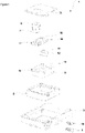
- the present invention relates to a cooling device (1) comprising: a body (2) having a cooling compartment, a door (3) for accessing the respective cooling compartment, an adjustable hinge assembly (4) comprising a housing (5) placed onto the door (3) wherein the housing (5) comprises a pivot (6), a base bracket (7) adapted to be fixed to the body (2) wherein the base bracket (7) comprises a counterpart pivot (8) which is adapted to engage pivotably with the pivot (6).
- the present invention relates to a cooling appliance (1) further comprising: the housing (5) accommodating a first screw (9) and a second screw (10) which upon activation by the user are adapted to move the housing (5) relative to the body (2) in the first horizontal direction (Y) and in the second horizontal direction (X) respectively wherein the said directions (X,Y) form a plane parallel to the ground and wherein the said screws (9 ,10) extend parallel to each other.
- the adjustable hinge assembly (4) comprises the housing (5) and the housing (5) comprises the pivot (6).
- the pivot (6) is in the shape of a circular hole, facing upwards.
- the base bracket (7) is fixed onto the body (2) on a side wall of the cooling appliance (1) and projects towards the front of the cooling appliance (1).
- the base bracket (7) has a counterpart pivot (8) at the front side of the base bracket (7) which is inserted inside the pivot (6) in a pivotable manner. Therefore, the door (3) is pivotable attached onto the body (2) which upon pivoting, provides access inside the body (2) or blocks access inside the body (2).
- the housing (5) is provided with two holes into which the first screw (9) and the second screw (10) is rotatably inserted. The user may rotate the said screws (9 ,10) via a screw driver or the like and depending on the direction of the rotation the said screws (9 ,10) go inside or outside the holes provided on the housing (5).
- the first screw (9), upon rotation, is configured to change the position of the housing (5) with respect to the base bracket (7) in a first horizontal direction (Y) perpendicular and away from the front of the cooling appliance (1).
- the second screw (10), upon rotation, is configured to change the position of the housing (5) with respect to the base bracket (7) in a second horizontal direction (X) perpendicular to the first horizontal direction (Y). Meaning that the housing (5) and the door (3) moves sideways with respect to the cooling appliance (1).
- the second horizontal direction (X) is parallel to the front of the cooling appliance (1).
- the first horizontal direction (Y) and the second horizontal direction (X) form a plane parallel to the ground frame.
- the adjustable hinge assembly (4) provides the door (3) to be moved away and sideways with respect to the cooling appliance (1) correcting the position of the door (3).
- the first screw (9) and the second screw (10) extend parallel and next to each other. Therefore, ease of use is provided for the user. Since the said screws (9,10) are adjacent to each other, the user may easily rotate the said screws (9,10) to adjust the position of the door (3) easily, eliminating the need for a maintenance service.
- the first screw (9) and the second screw (10) go inside the housing (5) and contact the first adjustment mechanism (11) and the second adjustment mechanism (12) respectively, the said adjustment mechanisms (11,12) provides the door (3) to be moved away and sideways with respect to the cooling appliance (1) correcting the position of the door (3).
- the users are provided with a robust and easily operable structure allowing the users to adjust the position of the door (3) easily, eliminating the need for a service technician, thereby reducing the costs for maintenance.
- the first adjustment mechanism (11) comprises the pivot (6).
- the first adjustment mechanism (11) is in the form of a rectangular prism, comprising the pivot (6) into which the counterpart pivot (8) is inserted.
- the first screw (9) upon activation by the user, depending on the direction of the rotation, moves the first adjustment mechanism (11), therefore changing the position of the door (3) with respect to the cooling appliance (1).
- the base bracket (7) has a fixed length, therefore the position of the counterpart pivot (8) and that of the first adjustment mechanism (11) remains the same with respect to the cooling appliance (1).
- the first adjustment mechanism (11) moves inside the housing (5) therefore forcing the adjustable hinge assembly (4) to move back and forth with respect to the cooling appliance (1) depending on the direction of the rotation.
- the adjustable hinge assembly (4) comprises an alignment bed (13) comprising a first recess (14) and a second recess (15) into which the first adjustment mechanism (11) and the second adjustment mechanism (12) is respectively placed.
- the alignment bed (13) comprises a pair of bores wherein the said bores coincide with the said holes provided on the housing (5). Therefore, the screw (9,10) is projected towards the alignment bed (13) and is at least partly inserted inside the alignment bed (13).
- One of the said bores leads the first screw (9) inside the first recess (14) and the other bore leads the second screw (10) inside the second recess (15).
- the first screw (9), upon activation by the user moves along the said hole and bore and contacts the first adjustment mechanism (11).
- the first adjustment mechanism (11) and the second adjustment mechanism (12) provides diagonal position adjustment of the door (3) with respect to the cooling appliance (1).
- the adjustable hinge assembly (4) comprises an alignment plate (16) placed onto the alignment bed (13) wherein the alignment plate (16) comprises a first slot (17) and a second slot (18) through which the first adjustment mechanism (11) is inserted into the first recess (14).
- the alignment bed (13) has a cutout on its upper side.
- the alignment plate (16) is placed form fittingly onto the said cutout.
- the cutout extends along the second horizontal direction (X) and is longer than the alignment plate (16).
- the first adjustment mechanism (11) is inserted into the first recess (14) by passing through the first slot (17).
- the second adjustment mechanism (12) is placed onto the alignment bed (13) before the alignment plate (16) is placed onto the alignment bed (13) thereby keeping the second adjustment mechanism (12) inside the alignment bed (13) in a non-removable manner.
- the second adjustment mechanism (12) comprises a lug (19) which is inserted inside the second slot (18).
- the second adjustment mechanism (12) has a lug (19) protruding upwards towards the alignment plate (16).
- the slot (18) is partly filled by the lug (19) upon placing the alignment plate (16) onto the alignment bed (13). Therefore, the movement of the second adjustment mechanism (12) is guided by the slot (18) and the lug (19).
- the extension direction of the second slot (18) forms an acute angle ( ⁇ ) in anti-clockwise direction with the movement direction of the second adjustment mechanism (12).
- the second adjustment mechanism (12) upon activation by the user moves along the second recess (15).
- the lug (19) forces the alignment plate (16) to slide in the second direction (X) since the extension direction of the second slot (18) forms an acute angle ( ⁇ ) in anti-clockwise direction with the movement direction of the second adjustment mechanism (12).
- the housing (5) is form fittingly placed in a recessed area provided on the door (3) forming a flat surface. As a result, the distance between the base bracket (7) and the door (3) is minimized.
- the adjustable hinge assembly (4) comprises a cover (20) forming a linear plane with the door (3).
- the cover (20) is placed onto the housing (5) so as to cover and separate the housing (5) from outer environment. Therefore, a robust structure is achieved.
- the cover (20) comprises an opening, providing the counterpart pivot (8) to enter inside the pivot (6).
- the head of the said screws (9.10) faces the body (2) in the closed position of the door (3). Therefore, the visibility of the said screws (9,10) is minimized meanwhile ensuring easy accessibility of the said screws (9,10).
- the position of the door (3) is adjusted by use of the adjustable hinge assembly (4), the adjustable hinge assembly (4) providing adjustment along a first horizontal direction (Y) and a second horizontal direction (X) in an easily operable manner, eliminating the costs related to assignments of technical repair staff.
Landscapes
- Engineering & Computer Science (AREA)
- Mechanical Engineering (AREA)
- Hinges (AREA)
Claims (6)
- Ein Kühlgerät (1) umfasst einen Körper (2) mit einem Kühlfach, eine Tür (3) zum Zugang zum jeweiligen Kühlfach, eine einstellbare Scharnieranordnung (4), die ein Gehäuse (5) umfasst, das an der Tür (3) platziert ist, wobei das Gehäuse (5) einen Drehpunkt (6) umfasst, eine Basishalterung (7), die angepasst ist, um an dem Körper (2) befestigt zu werden, wobei die Basishalterung (7) einen Gegenzapfen (8) umfasst, der geeignet ist, schwenkbar mit dem Drehpunkt (6) in Eingriff zu kommen, wobei das Gehäuse (5) die erste Schraube (9) aufnimmt, die bei Aktivierung durch den Benutzer angepasst ist, das Gehäuse (5) relativ zum Körper (2) in der ersten horizontalen Richtung (X) zu bewegen, gekennzeichnet ist es dadurch, dass das Gehäuse (5) eine zweite Schraube (10) aufnimmt, die bei Aktivierung durch den Benutzer angepasst ist, um das Gehäuse (5) relativ zu dem Körper (2) in der zweiten horizontalen Richtung (Y) zu bewegen, wobei die Richtungen ( X, Y) eine Ebene parallel zum Boden bilden und wobei sich die Schrauben (9, 10) parallel zueinander erstrecken; wobei die erste Schraube (9) und die zweite Schraube (10) bei Aktivierung durch den Benutzer einen ersten Einstellmechanismus (11) bzw. einen zweiten Einstellmechanismus (12), die innerhalb des Gehäuses (5) untergebracht sind, die sich in einer Richtung parallel zueinander bewegen, wobei die einstellbare Scharnieranordnung (4) ein Ausrichtungsbett (13) umfasst, das eine erste Aussparung (14) und eine zweite Aussparung (15) umfasst, in denen der erste Einstellmechanismus (11) und der zweite Einstellmechanismus (12) jeweils platziert sind, und die einstellbare Scharnieranordnung (4) eine Ausrichtungsplatte (16) umfasst, die auf dem Ausrichtungsbett (13) angeordnet ist, wobei die Ausrichtungsplatte (16) einen ersten Schlitz (17) und einen zweiten Schlitz (18) umfasst, wobei der erste Einstellmechanismus (11) durch den ersten Schlitz (17) in die erste Aussparung (14) eingeführt ist und die Erstreckungsrichtung des zweiten Schlitzes (18) mit der Bewegung einen spitzen Winkel (α) entgegen dem Uhrzeigersinn Richtung des zweiten Einstellmechanismus (12) bildet.
- Ein Kühlgerät (1), wie in Anspruch 1 aufgeführt, ist dadurch gekennzeichnet, dass der erste Einstellmechanismus (11) den Drehpunkt (6) umfasst.
- Ein Kühlgerät (1), wie in Anspruch 1 oder 2 aufgeführt, ist dadurch gekennzeichnet, dass der zweite Einstellmechanismus (12) eine Lasche (19) umfasst, die in den zweiten Schlitz (18) eingesetzt ist.
- Ein Kühlgerät (1), wie in einem der vorherigen Ansprüchen aufgeführt, ist dadurch gekennzeichnet, dass das Gehäuse (5) formschlüssig in einer an der Tür (3) vorgesehenen Vertiefung eingesetzt ist, die eine ebene Fläche bildet.
- Ein Kühlgerät (1), wie in einem der vorherigen Ansprüchen aufgeführt, ist dadurch gekennzeichnet, dass die einstellbare Scharnieranordnung (4) eine Abdeckung (20) umfasst, die mit der Tür (3) eine lineare Ebene bildet.
- Ein Kühlgerät (1), wie in einem der vorherigen Ansprüchen aufgeführt, ist dadurch gekennzeichnet, dass die Köpfe der Schrauben (9, 10) in der Schließstellung der Tür (3) dem Körper (2) zugewandt sind.
Applications Claiming Priority (2)
| Application Number | Priority Date | Filing Date | Title |
|---|---|---|---|
| TR2019/04277A TR201904277A2 (tr) | 2019-03-22 | 2019-03-22 | Ayarlanabi̇li̇r menteşe si̇stemi̇ i̇çeren soğutucu ci̇haz |
| PCT/EP2020/054611 WO2020193029A1 (en) | 2019-03-22 | 2020-02-21 | A cooling appliance having an adjustable hinge assembly |
Publications (2)
| Publication Number | Publication Date |
|---|---|
| EP3942136A1 EP3942136A1 (de) | 2022-01-26 |
| EP3942136B1 true EP3942136B1 (de) | 2023-01-25 |
Family
ID=69740329
Family Applications (1)
| Application Number | Title | Priority Date | Filing Date |
|---|---|---|---|
| EP20708447.6A Active EP3942136B1 (de) | 2019-03-22 | 2020-02-21 | Kühlgerät mit einstellbarer scharnieranordnung |
Country Status (4)
| Country | Link |
|---|---|
| EP (1) | EP3942136B1 (de) |
| PL (1) | PL3942136T3 (de) |
| TR (1) | TR201904277A2 (de) |
| WO (1) | WO2020193029A1 (de) |
Family Cites Families (5)
| Publication number | Priority date | Publication date | Assignee | Title |
|---|---|---|---|---|
| DE3218837C2 (de) * | 1982-05-19 | 1986-03-13 | Licentia Patent-Verwaltungs-Gmbh, 6000 Frankfurt | Einstellvorrichtung für Türen von Kühl- oder Gefriergeräten |
| US9605457B2 (en) * | 2008-10-29 | 2017-03-28 | Steven Humble | Three-dimensionally adjustable pivot device |
| JP5642449B2 (ja) * | 2010-08-16 | 2014-12-17 | 株式会社Skb | ピボットヒンジ |
| WO2017059909A1 (en) | 2015-10-08 | 2017-04-13 | Arcelik Anonim Sirketi | Adjustable hinge assembly for use in a refrigerator |
| CN206829871U (zh) * | 2017-05-15 | 2018-01-02 | 广东顶固集创家居股份有限公司 | 输出位置可三维调节的天地铰链 |
-
2019
- 2019-03-22 TR TR2019/04277A patent/TR201904277A2/tr unknown
-
2020
- 2020-02-21 WO PCT/EP2020/054611 patent/WO2020193029A1/en not_active Ceased
- 2020-02-21 PL PL20708447.6T patent/PL3942136T3/pl unknown
- 2020-02-21 EP EP20708447.6A patent/EP3942136B1/de active Active
Also Published As
| Publication number | Publication date |
|---|---|
| PL3942136T3 (pl) | 2023-06-19 |
| TR201904277A2 (tr) | 2020-10-21 |
| WO2020193029A1 (en) | 2020-10-01 |
| EP3942136A1 (de) | 2022-01-26 |
Similar Documents
| Publication | Publication Date | Title |
|---|---|---|
| JP7315716B2 (ja) | 家具駆動装置 | |
| US6845544B2 (en) | Hinge for furniture | |
| US9181743B2 (en) | Door opening/closing device unit and method for mounting the same | |
| US8789240B2 (en) | Hinge for a panel door, in particular for a cooling cupboard | |
| CA2634910C (en) | Two-stage adjustable door hinge | |
| CA2876877C (en) | Door closer mechanism for display case | |
| KR20040096688A (ko) | 빌트인 저장고 | |
| JP2017528270A (ja) | 調節装置 | |
| US20070164646A1 (en) | Domestic appliance having a swiveled display screen | |
| EP3942136B1 (de) | Kühlgerät mit einstellbarer scharnieranordnung | |
| CA3085541C (en) | Furniture board having a hinge and furniture item having such a furniture board | |
| US9151536B2 (en) | Refrigeration device comprising a dispensing device | |
| CN106705546A (zh) | 冰箱 | |
| KR200489994Y1 (ko) | 미닫이 도어용 호차의 높낮이 조절장치 | |
| US20030066164A1 (en) | Adjustable door hinge | |
| KR20180092133A (ko) | 냉장고 및 냉장고의 서랍식 도어 | |
| CN219158721U (zh) | 一种三维可调铝框门阻尼铰链装置 | |
| CN221650788U (zh) | 一种投影显示装置以及电器设备 | |
| JP4263237B2 (ja) | 収納庫の引き戸 | |
| JPWO2019163342A1 (ja) | ヒンジ | |
| JP3007317B2 (ja) | 弾球遊技機 | |
| JP2023092341A (ja) | ドア位置調整機構及び冷蔵庫 | |
| KR101391747B1 (ko) | 가구용 도어 힌지 | |
| CN119373382A (zh) | 一种连接装置及柜子 | |
| CN119713713A (zh) | 调节装置及嵌入式制冷设备 |
Legal Events
| Date | Code | Title | Description |
|---|---|---|---|
| STAA | Information on the status of an ep patent application or granted ep patent |
Free format text: STATUS: UNKNOWN |
|
| STAA | Information on the status of an ep patent application or granted ep patent |
Free format text: STATUS: THE INTERNATIONAL PUBLICATION HAS BEEN MADE |
|
| PUAI | Public reference made under article 153(3) epc to a published international application that has entered the european phase |
Free format text: ORIGINAL CODE: 0009012 |
|
| STAA | Information on the status of an ep patent application or granted ep patent |
Free format text: STATUS: REQUEST FOR EXAMINATION WAS MADE |
|
| 17P | Request for examination filed |
Effective date: 20210831 |
|
| AK | Designated contracting states |
Kind code of ref document: A1 Designated state(s): AL AT BE BG CH CY CZ DE DK EE ES FI FR GB GR HR HU IE IS IT LI LT LU LV MC MK MT NL NO PL PT RO RS SE SI SK SM TR |
|
| DAV | Request for validation of the european patent (deleted) | ||
| DAX | Request for extension of the european patent (deleted) | ||
| GRAP | Despatch of communication of intention to grant a patent |
Free format text: ORIGINAL CODE: EPIDOSNIGR1 |
|
| STAA | Information on the status of an ep patent application or granted ep patent |
Free format text: STATUS: GRANT OF PATENT IS INTENDED |
|
| INTG | Intention to grant announced |
Effective date: 20221110 |
|
| RIN1 | Information on inventor provided before grant (corrected) |
Inventor name: EVREN, IBRAHIM YILMAZ Inventor name: AKYUZ, ERCAN Inventor name: YAVUZ, RESUL Inventor name: EROL, SEMIH Inventor name: INAL, TAYFUN |
|
| GRAS | Grant fee paid |
Free format text: ORIGINAL CODE: EPIDOSNIGR3 |
|
| GRAA | (expected) grant |
Free format text: ORIGINAL CODE: 0009210 |
|
| STAA | Information on the status of an ep patent application or granted ep patent |
Free format text: STATUS: THE PATENT HAS BEEN GRANTED |
|
| AK | Designated contracting states |
Kind code of ref document: B1 Designated state(s): AL AT BE BG CH CY CZ DE DK EE ES FI FR GB GR HR HU IE IS IT LI LT LU LV MC MK MT NL NO PL PT RO RS SE SI SK SM TR |
|
| REG | Reference to a national code |
Ref country code: GB Ref legal event code: FG4D |
|
| REG | Reference to a national code |
Ref country code: CH Ref legal event code: EP |
|
| REG | Reference to a national code |
Ref country code: AT Ref legal event code: REF Ref document number: 1546019 Country of ref document: AT Kind code of ref document: T Effective date: 20230215 Ref country code: IE Ref legal event code: FG4D |
|
| REG | Reference to a national code |
Ref country code: DE Ref legal event code: R096 Ref document number: 602020007858 Country of ref document: DE |
|
| REG | Reference to a national code |
Ref country code: LT Ref legal event code: MG9D |
|
| REG | Reference to a national code |
Ref country code: NL Ref legal event code: MP Effective date: 20230125 |
|
| REG | Reference to a national code |
Ref country code: AT Ref legal event code: MK05 Ref document number: 1546019 Country of ref document: AT Kind code of ref document: T Effective date: 20230125 |
|
| PG25 | Lapsed in a contracting state [announced via postgrant information from national office to epo] |
Ref country code: NL Free format text: LAPSE BECAUSE OF FAILURE TO SUBMIT A TRANSLATION OF THE DESCRIPTION OR TO PAY THE FEE WITHIN THE PRESCRIBED TIME-LIMIT Effective date: 20230125 |
|
| PG25 | Lapsed in a contracting state [announced via postgrant information from national office to epo] |
Ref country code: RS Free format text: LAPSE BECAUSE OF FAILURE TO SUBMIT A TRANSLATION OF THE DESCRIPTION OR TO PAY THE FEE WITHIN THE PRESCRIBED TIME-LIMIT Effective date: 20230125 Ref country code: PT Free format text: LAPSE BECAUSE OF FAILURE TO SUBMIT A TRANSLATION OF THE DESCRIPTION OR TO PAY THE FEE WITHIN THE PRESCRIBED TIME-LIMIT Effective date: 20230525 Ref country code: NO Free format text: LAPSE BECAUSE OF FAILURE TO SUBMIT A TRANSLATION OF THE DESCRIPTION OR TO PAY THE FEE WITHIN THE PRESCRIBED TIME-LIMIT Effective date: 20230425 Ref country code: LV Free format text: LAPSE BECAUSE OF FAILURE TO SUBMIT A TRANSLATION OF THE DESCRIPTION OR TO PAY THE FEE WITHIN THE PRESCRIBED TIME-LIMIT Effective date: 20230125 Ref country code: LT Free format text: LAPSE BECAUSE OF FAILURE TO SUBMIT A TRANSLATION OF THE DESCRIPTION OR TO PAY THE FEE WITHIN THE PRESCRIBED TIME-LIMIT Effective date: 20230125 Ref country code: HR Free format text: LAPSE BECAUSE OF FAILURE TO SUBMIT A TRANSLATION OF THE DESCRIPTION OR TO PAY THE FEE WITHIN THE PRESCRIBED TIME-LIMIT Effective date: 20230125 Ref country code: ES Free format text: LAPSE BECAUSE OF FAILURE TO SUBMIT A TRANSLATION OF THE DESCRIPTION OR TO PAY THE FEE WITHIN THE PRESCRIBED TIME-LIMIT Effective date: 20230125 Ref country code: AT Free format text: LAPSE BECAUSE OF FAILURE TO SUBMIT A TRANSLATION OF THE DESCRIPTION OR TO PAY THE FEE WITHIN THE PRESCRIBED TIME-LIMIT Effective date: 20230125 |
|
| PG25 | Lapsed in a contracting state [announced via postgrant information from national office to epo] |
Ref country code: SE Free format text: LAPSE BECAUSE OF FAILURE TO SUBMIT A TRANSLATION OF THE DESCRIPTION OR TO PAY THE FEE WITHIN THE PRESCRIBED TIME-LIMIT Effective date: 20230125 Ref country code: IS Free format text: LAPSE BECAUSE OF FAILURE TO SUBMIT A TRANSLATION OF THE DESCRIPTION OR TO PAY THE FEE WITHIN THE PRESCRIBED TIME-LIMIT Effective date: 20230525 Ref country code: GR Free format text: LAPSE BECAUSE OF FAILURE TO SUBMIT A TRANSLATION OF THE DESCRIPTION OR TO PAY THE FEE WITHIN THE PRESCRIBED TIME-LIMIT Effective date: 20230426 Ref country code: FI Free format text: LAPSE BECAUSE OF FAILURE TO SUBMIT A TRANSLATION OF THE DESCRIPTION OR TO PAY THE FEE WITHIN THE PRESCRIBED TIME-LIMIT Effective date: 20230125 |
|
| REG | Reference to a national code |
Ref country code: CH Ref legal event code: PL |
|
| REG | Reference to a national code |
Ref country code: BE Ref legal event code: MM Effective date: 20230228 |
|
| REG | Reference to a national code |
Ref country code: DE Ref legal event code: R097 Ref document number: 602020007858 Country of ref document: DE |
|
| PG25 | Lapsed in a contracting state [announced via postgrant information from national office to epo] |
Ref country code: SM Free format text: LAPSE BECAUSE OF FAILURE TO SUBMIT A TRANSLATION OF THE DESCRIPTION OR TO PAY THE FEE WITHIN THE PRESCRIBED TIME-LIMIT Effective date: 20230125 Ref country code: RO Free format text: LAPSE BECAUSE OF FAILURE TO SUBMIT A TRANSLATION OF THE DESCRIPTION OR TO PAY THE FEE WITHIN THE PRESCRIBED TIME-LIMIT Effective date: 20230125 Ref country code: MC Free format text: LAPSE BECAUSE OF FAILURE TO SUBMIT A TRANSLATION OF THE DESCRIPTION OR TO PAY THE FEE WITHIN THE PRESCRIBED TIME-LIMIT Effective date: 20230125 Ref country code: LU Free format text: LAPSE BECAUSE OF NON-PAYMENT OF DUE FEES Effective date: 20230221 Ref country code: LI Free format text: LAPSE BECAUSE OF NON-PAYMENT OF DUE FEES Effective date: 20230228 Ref country code: EE Free format text: LAPSE BECAUSE OF FAILURE TO SUBMIT A TRANSLATION OF THE DESCRIPTION OR TO PAY THE FEE WITHIN THE PRESCRIBED TIME-LIMIT Effective date: 20230125 Ref country code: DK Free format text: LAPSE BECAUSE OF FAILURE TO SUBMIT A TRANSLATION OF THE DESCRIPTION OR TO PAY THE FEE WITHIN THE PRESCRIBED TIME-LIMIT Effective date: 20230125 Ref country code: CZ Free format text: LAPSE BECAUSE OF FAILURE TO SUBMIT A TRANSLATION OF THE DESCRIPTION OR TO PAY THE FEE WITHIN THE PRESCRIBED TIME-LIMIT Effective date: 20230125 Ref country code: CH Free format text: LAPSE BECAUSE OF NON-PAYMENT OF DUE FEES Effective date: 20230228 |
|
| PG25 | Lapsed in a contracting state [announced via postgrant information from national office to epo] |
Ref country code: SK Free format text: LAPSE BECAUSE OF FAILURE TO SUBMIT A TRANSLATION OF THE DESCRIPTION OR TO PAY THE FEE WITHIN THE PRESCRIBED TIME-LIMIT Effective date: 20230125 |
|
| PLBE | No opposition filed within time limit |
Free format text: ORIGINAL CODE: 0009261 |
|
| STAA | Information on the status of an ep patent application or granted ep patent |
Free format text: STATUS: NO OPPOSITION FILED WITHIN TIME LIMIT |
|
| REG | Reference to a national code |
Ref country code: IE Ref legal event code: MM4A |
|
| 26N | No opposition filed |
Effective date: 20231026 |
|
| PG25 | Lapsed in a contracting state [announced via postgrant information from national office to epo] |
Ref country code: SI Free format text: LAPSE BECAUSE OF FAILURE TO SUBMIT A TRANSLATION OF THE DESCRIPTION OR TO PAY THE FEE WITHIN THE PRESCRIBED TIME-LIMIT Effective date: 20230125 Ref country code: IE Free format text: LAPSE BECAUSE OF NON-PAYMENT OF DUE FEES Effective date: 20230221 Ref country code: FR Free format text: LAPSE BECAUSE OF NON-PAYMENT OF DUE FEES Effective date: 20230325 |
|
| PG25 | Lapsed in a contracting state [announced via postgrant information from national office to epo] |
Ref country code: BE Free format text: LAPSE BECAUSE OF NON-PAYMENT OF DUE FEES Effective date: 20230228 |
|
| PG25 | Lapsed in a contracting state [announced via postgrant information from national office to epo] |
Ref country code: IT Free format text: LAPSE BECAUSE OF FAILURE TO SUBMIT A TRANSLATION OF THE DESCRIPTION OR TO PAY THE FEE WITHIN THE PRESCRIBED TIME-LIMIT Effective date: 20230125 |
|
| PG25 | Lapsed in a contracting state [announced via postgrant information from national office to epo] |
Ref country code: BG Free format text: LAPSE BECAUSE OF FAILURE TO SUBMIT A TRANSLATION OF THE DESCRIPTION OR TO PAY THE FEE WITHIN THE PRESCRIBED TIME-LIMIT Effective date: 20230125 |
|
| PG25 | Lapsed in a contracting state [announced via postgrant information from national office to epo] |
Ref country code: BG Free format text: LAPSE BECAUSE OF FAILURE TO SUBMIT A TRANSLATION OF THE DESCRIPTION OR TO PAY THE FEE WITHIN THE PRESCRIBED TIME-LIMIT Effective date: 20230125 |
|
| PGFP | Annual fee paid to national office [announced via postgrant information from national office to epo] |
Ref country code: DE Payment date: 20250218 Year of fee payment: 6 |
|
| PGFP | Annual fee paid to national office [announced via postgrant information from national office to epo] |
Ref country code: PL Payment date: 20250213 Year of fee payment: 6 |
|
| PGFP | Annual fee paid to national office [announced via postgrant information from national office to epo] |
Ref country code: GB Payment date: 20250220 Year of fee payment: 6 |
|
| PGFP | Annual fee paid to national office [announced via postgrant information from national office to epo] |
Ref country code: TR Payment date: 20250123 Year of fee payment: 6 |
|
| PG25 | Lapsed in a contracting state [announced via postgrant information from national office to epo] |
Ref country code: CY Free format text: LAPSE BECAUSE OF FAILURE TO SUBMIT A TRANSLATION OF THE DESCRIPTION OR TO PAY THE FEE WITHIN THE PRESCRIBED TIME-LIMIT; INVALID AB INITIO Effective date: 20200221 |
|
| PG25 | Lapsed in a contracting state [announced via postgrant information from national office to epo] |
Ref country code: HU Free format text: LAPSE BECAUSE OF FAILURE TO SUBMIT A TRANSLATION OF THE DESCRIPTION OR TO PAY THE FEE WITHIN THE PRESCRIBED TIME-LIMIT; INVALID AB INITIO Effective date: 20200221 |