EP3941635B1 - Zerkleinerer - Google Patents
Zerkleinerer Download PDFInfo
- Publication number
- EP3941635B1 EP3941635B1 EP20773700.8A EP20773700A EP3941635B1 EP 3941635 B1 EP3941635 B1 EP 3941635B1 EP 20773700 A EP20773700 A EP 20773700A EP 3941635 B1 EP3941635 B1 EP 3941635B1
- Authority
- EP
- European Patent Office
- Prior art keywords
- crushing
- crusher
- shaft
- crushing head
- cylinders
- Prior art date
- Legal status (The legal status is an assumption and is not a legal conclusion. Google has not performed a legal analysis and makes no representation as to the accuracy of the status listed.)
- Active
Links
Images


Classifications
-
- B—PERFORMING OPERATIONS; TRANSPORTING
- B02—CRUSHING, PULVERISING, OR DISINTEGRATING; PREPARATORY TREATMENT OF GRAIN FOR MILLING
- B02C—CRUSHING, PULVERISING, OR DISINTEGRATING IN GENERAL; MILLING GRAIN
- B02C2/00—Crushing or disintegrating by gyratory or cone crushers
- B02C2/02—Crushing or disintegrating by gyratory or cone crushers eccentrically moved
- B02C2/04—Crushing or disintegrating by gyratory or cone crushers eccentrically moved with vertical axis
-
- B—PERFORMING OPERATIONS; TRANSPORTING
- B02—CRUSHING, PULVERISING, OR DISINTEGRATING; PREPARATORY TREATMENT OF GRAIN FOR MILLING
- B02C—CRUSHING, PULVERISING, OR DISINTEGRATING IN GENERAL; MILLING GRAIN
- B02C25/00—Control arrangements specially adapted for crushing or disintegrating
-
- B—PERFORMING OPERATIONS; TRANSPORTING
- B02—CRUSHING, PULVERISING, OR DISINTEGRATING; PREPARATORY TREATMENT OF GRAIN FOR MILLING
- B02C—CRUSHING, PULVERISING, OR DISINTEGRATING IN GENERAL; MILLING GRAIN
- B02C2/00—Crushing or disintegrating by gyratory or cone crushers
- B02C2/02—Crushing or disintegrating by gyratory or cone crushers eccentrically moved
- B02C2/04—Crushing or disintegrating by gyratory or cone crushers eccentrically moved with vertical axis
- B02C2/045—Crushing or disintegrating by gyratory or cone crushers eccentrically moved with vertical axis and with bowl adjusting or controlling mechanisms
-
- B—PERFORMING OPERATIONS; TRANSPORTING
- B02—CRUSHING, PULVERISING, OR DISINTEGRATING; PREPARATORY TREATMENT OF GRAIN FOR MILLING
- B02C—CRUSHING, PULVERISING, OR DISINTEGRATING IN GENERAL; MILLING GRAIN
- B02C2/00—Crushing or disintegrating by gyratory or cone crushers
- B02C2/02—Crushing or disintegrating by gyratory or cone crushers eccentrically moved
- B02C2/04—Crushing or disintegrating by gyratory or cone crushers eccentrically moved with vertical axis
- B02C2/047—Crushing or disintegrating by gyratory or cone crushers eccentrically moved with vertical axis and with head adjusting or controlling mechanisms
-
- Y—GENERAL TAGGING OF NEW TECHNOLOGICAL DEVELOPMENTS; GENERAL TAGGING OF CROSS-SECTIONAL TECHNOLOGIES SPANNING OVER SEVERAL SECTIONS OF THE IPC; TECHNICAL SUBJECTS COVERED BY FORMER USPC CROSS-REFERENCE ART COLLECTIONS [XRACs] AND DIGESTS
- Y02—TECHNOLOGIES OR APPLICATIONS FOR MITIGATION OR ADAPTATION AGAINST CLIMATE CHANGE
- Y02W—CLIMATE CHANGE MITIGATION TECHNOLOGIES RELATED TO WASTEWATER TREATMENT OR WASTE MANAGEMENT
- Y02W30/00—Technologies for solid waste management
- Y02W30/50—Reuse, recycling or recovery technologies
- Y02W30/62—Plastics recycling; Rubber recycling
Definitions
- the present disclosure relates to a crusher. More particularly, the present disclosure relates to a drive mechanism for a crusher.
- Crushers such as cone crushers and gyratory crushers, are used to crush ore or large rocks into smaller rocks, gravel or dust.
- the crushers can also be used for recycling waste material such as for crushing plastics material into finer particulates.
- a crusher has a housing supporting an outer crushing shell and in which is located a crushing head supporting an inner crushing shell. The crushing head is moved to crush the feed ore between the outer crushing shell and the inner crushing shell.
- the desired size of the finer particulate matter is regulated by setting the minimum width of a crushing gap formed between the outer and inner crushing shells.
- One type of cone crusher utilises an eccentric member to cause movement of the crushing head.
- the shaft of the crushing head is mounted in the eccentric member and, during use, the eccentric member causes the shaft to move along a predefined path to cause movement of the crushing head.
- Prior art examples of such eccentric drives can be seen in US 5,115,991 , US3666188 A , CN102327791 , WO02/089987A1 and US 5,718,391 .
- One problem encountered with the use of such an eccentric member is that it is cumbersome to change the predefined path of movement of the shaft - normally this requires the cone crusher to be dismantled so that the eccentric member can be exchanged for another. It is often also difficult to adjust the minimum size of the crushing gap between the housing and the crushing head.
- the crushing head rests in a spherical bearing and its shaft is held in a cylindrical sleeve having an unbalanced mass attached thereto.
- the unbalanced mass is rotated and this causes it to swing radially outwardly due to centrifugal forces acting on the sleeve - which in turn causes the crushing head to gyrate within the spherical bearing.
- the gyration path (and the crushing gap) can be selectively changed by either altering the speed of rotation of the sleeve, by altering the mass of the unbalanced mass, or by changing the distance between the unbalanced mass and the sleeve.
- CN 207102703 also discloses a gyratory (inertia) cone crusher equivalent to the above but being further provided with a cavity protection device.
- Its drive mechanism includes a pulley that drives a transmission shaft so that torque is transmitted to the main shaft of the crushing head, thereby to cause rotation of the unbalanced mass to generate the breaking force.
- the cavity protection device is in the form of a shock absorber located around the crushing head and configured to prevent the crushing head from directly contacting the crushing shell should the movement of the crushing head become too extreme.
- the shock absorbers are preferably elastic rubber air springs, but they can also be hydraulic cylinders. However, these hydraulic cylinders do not impart driving force to the crushing head as any such force would conflict with the breaking force generated by the unbalanced mass.
- a crusher for crushing material into finer particulates comprising
- the drive mechanism may be configured to generate movement of the crushing head by imparting only a pulling force on the shaft.
- the crushing head may be supported on a spherical bearing which may include one or more bearing pads.
- the drive units may be configured to be selectively activated to generate movement of the crushing head relative to the housing. In some embodiments the drive units are located within the housing, whereas in other embodiments the drive units are located outside the housing.
- the crusher may include a coupling mounted on the shaft, with each drive unit being joined to the coupling via a tie rod.
- Each tie rod may be pivotally joined to the coupling and may be pivotally joined to its drive unit.
- Each tie rod may be joined to the coupling and its drive unit via universal joints or constant-velocity joints.
- the crusher may include a counterweight mounted on the shaft, wherein the counterweight is spaced away from the crushing head and wherein the drive units are joined to the shaft between the crushing head and the counterweight.
- the counterweight may be connected to the shaft and configured to rotate together with the crushing head. Alternatively, the counterweight may be connected to the shaft but configured to rotate independently from the crushing head. In some embodiments the counterweight may be integrally formed with the coupling.
- Each of the drive units may be one of a hydraulic cylinder, a linear motor and a solenoid.
- the drive mechanism may include a hydraulic circuit being configured to selectively activate each of the cylinders.
- the hydraulic circuit may include a proportional directional control valve being configured to control flow of hydraulic fluid into or out from each cylinder.
- the control valve is a three-position pilot operated proportional directional control valve.
- the control valve may be configured in a failsafe default configuration to open its tank port and close its pump port.
- the hydraulic circuit may be configured that when one of the cylinders is selectively activated, the pulling force exerted by that activated cylinder operates to exhaust hydraulic fluid from other cylinders.
- the hydraulic circuit may include a bleed fluid line leading from each cylinder, wherein during use each bleed fluid line is configured to bleed off a portion of hydraulic fluid from its cylinder and wherein the hydraulic circuit is replenished by fresh hydraulic fluid. Such replacement of the portion of the hydraulic fluid may assist in regulating a temperature of the hydraulic fluid in the hydraulic circuit.
- Each cylinder may be associated with one or more bearing pads, with each bleed fluid line leading from its cylinder to the bearing pads so that, in use, the portion of hydraulic fluid flowing through the bleed fluid line is ejected between the bearing pads and the crushing head.
- Each bleed fluid line may lead to a distribution manifold for dispersing hydraulic fluid to any one or more of all the bearing pads.
- the crusher may include one-way valves provided between each of the cylinders and the distribution manifold, the valves being configured to prevent hydraulic fluid flowing from the distribution manifold back to the cylinders.
- the hydraulic circuit may be operable to adjust a pressure of the hydraulic fluid within the cylinders, thereby to select a desired operational crushing pressure to be exerted by the crushing head during use.
- the hydraulic circuit may be operable to adjust a volume of the hydraulic fluid within the cylinders, thereby to select a desired operational width of the crushing gap during use.
- the crusher may include a positional sensing mechanism being configured to determine an operative position of the crushing head within the housing.
- the positional sensing mechanism may be any one of (a) each drive unit being a position sensing drive unit configured to detect a position of its actuator; (b) a proximity sensor being associated with each drive unit, wherein the proximity sensors are configured to detect the proximity of the shaft to their associated drive units; and (c) an angular sensor configured to detect the angular position and orientation of the shaft within the housing.
- the crusher may be a cone crusher or a gyratory crusher.
- a tie rod for use in a crusher as described in the first aspect.
- a hydraulic cylinder for use in a crusher as described in the first aspect.
- a method of operating a crusher having a housing supporting an outer crushing shell and further having a crushing head located within the housing and being mounted on a shaft, the crushing head supporting an inner crushing shell that cooperates with the outer crushing shell to form a crushing gap therebetween, the method comprising the step of providing a coupling mounted on the shaft, whereby the coupling is able to rotate around the shaft, and joining a drive mechanism comprising at least three drive units to the coupling for generating movement of the inner crushing shell relative to the outer crushing shell.
- the method may include the step of having the drive mechanism generating movement of the crushing head by imparting only a pulling force on the shaft.
- the method may include the step of selectively activating each of the drive units to generate movement of the crushing head relative to the housing.
- Each of the drive units may be one of a hydraulic cylinder, a linear motor and a solenoid.
- the method may include the step of utilising a force exerted by a cylinder that is selectively activated to exhaust hydraulic fluid from other cylinders.
- the method may include the step of replacing a portion of hydraulic fluid used in the hydraulic drive mechanism when each of the cylinders is selectively activated. Such replacement of the portion of the hydraulic fluid may assist in regulating a temperature of the hydraulic fluid.
- the crushing head may be supported on a bearing, wherein the method includes the step of ejecting the portion of hydraulic fluid between the bearing and the crushing head.
- the method may include the step of adjusting a pressure of hydraulic fluid used in the hydraulic drive mechanism to thereby select a desired crushing pressure to be exerted by the crushing head.
- Each cylinder may include a piston reciprocally movable between an inner position proximal to the shaft and an outer position distal to the shaft, wherein the method further includes the steps of selectively activating and deactivating each of the cylinders to generate orbital or gyratory movement of the crushing head relative to the outer crushing shell, wherein each cylinder is activated while its piston is moving from its inner position towards its outer position and each cylinder is deactivated while its piston is moving from its outer position towards its inner position.
- the step of activating each of the cylinders may include injecting hydraulic fluid into each respective cylinder thereby to apply movement force to its piston and the step of deactivating each of the cylinders may include permitting the passive movement of each piston to exhaust hydraulic fluid from its cylinder.
- the method may include the steps of activating each cylinder after its piston moves past its inner dead centre position and deactivating each cylinder after its piston moves past its outer dead centre position.
- the method may include the steps of providing a processing unit having a memory module and of storing a minimum inner dead centre position for each piston and a maximum outer dead centre position for each piston in the memory module.
- the method may include the step of programming the processing unit with a desired operational crushing pressure to be exerted by the crushing head, whereby during use the processing unit is arranged to adjust the pressure of hydraulic fluid injected into the cylinders to obtain the desired operational crushing pressure.
- the method may include the step of programming the processing unit with a desired operational displacement of the crushing head, whereby during use the processing unit is arranged to adjust the volume of hydraulic fluid injected into the cylinders to obtain the desired operational displacement.
- the volume of hydraulic fluid injected into the cylinders may be selectively increased to increase the extent of movement of the crushing head and decreased to decrease the extent of movement of the crushing head.
- the method may include the step of programming the processing unit with a desired operational crushing pressure to be exerted by the crushing head,
- One or more position sensors may be associated with the drive units, wherein the method may include the step of determining the operative position of the crushing head within the housing.
- the drive units may be spaced substantially equidistantly around the shaft.
- the method may include the step of activating the drive units consecutively in a desired order around the shaft.
- the drive mechanism may include at least five drive units and, in some embodiments, the method may include the step of concurrently activating at least two of the drive units.
- the method may be used for operating a cone crusher or a gyratory crusher.
- the present disclosure relates to a crusher that is used for crushing solid material, such as ore, and more particularly to a drive mechanism for such a crusher.
- the crusher will typically be a cone crusher or a gyratory crusher.
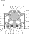
- FIG. 1 and 2 of the drawings there is shown a first embodiment of a cone crusher 10 which is used, for example, for crushing coarse ore into finer particle size ore.
- the cone crusher 10 comprises a housing 12 defining a chamber 14 for containing the various operational parts of the cone crusher 10.
- the housing 12 includes a lower bowl body 16 that is closed at its upper end by a removable lid 18.
- a frusto-conical opening 20 extends through the lid 18, through which opening 20 the feed ore can pass into the chamber 14 during use.
- a frusto-conical outer crushing shell 22 (also known in the art as a bowl liner) is supported by the housing 12 so as to line the opening 20.
- a crushing head 24 is located inside the chamber 14 with the crushing head 24 being mounted on a shaft 26.
- the crushing head 24 is conical in shape and extends at least partially into and/or through the opening 20.
- the crushing head 24 supports an inner crushing shell 28 (also known in the art as a mantle) that is secured in place by a cap 30 being joined to the shaft 26.
- the inner crushing shell 28 can be secured to the crushing head 24 by any other conventional methods.
- the inner crushing shell 28 can be integrally formed as part of the crushing head 24.
- the space between the outer crushing shell 22 and the inner crushing shell 28 defines a crushing gap 32. Due to the outer crushing shell 22 having a narrower cone angle than that of the inner crushing shell 28, the crushing gap 32 is wider near the outer side of the lid 18 and narrower near the inner side of the lid 18.
- Both the outer crushing shell 22 and the inner crushing shell 28 are wear items and are configured to be replaced when needed.
- the position of lid 18 and/or the crushing head 24 are able to be adjusted, whereby lid 18 can be moved closer to or further from crushing head 24 to provide one method of adjusting the size of the crushing gap 32.
- the crushing head 24 is movably supported within the chamber 14 on a spherical support or bearing 34 which itself is mounted on an inner frame 36.
- the bearing 34 can be made of a single bearing pad or the bearing 34 can comprise multiple bearing pads. In the latter case, the bearing pads can be positioned directly adjacent to each other or spaced slightly apart from each other.
- the inner frame 36 is substantially cylindrical and stands on a floor 38 of the bowl body 16.
- Inner frame 36 has an outwardly projecting flange 40 located approximately midway along its height, which is arranged to rest on and be joined to a collar 42 projecting inwardly from a side wall 44 of the bowl body 16 to fix the inner frame 36 to the bowl body 16.
- Inner frame 36 supports a drive mechanism 46 that is joined to shaft 26 for causing gyratory movement of the crushing head 24. During use this movement is normally of either an orbital or a gyratory nature.
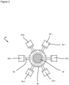
- the drive mechanism 46 comprises a number of drive units that, in the exemplary embodiment, are hydraulic cylinders 48 and pistons 50 being spaced around the shaft 26. It is envisaged that the drive mechanism 46 will generally have between three and ten cylinders 48, however, it may be that additional cylinders need to be provided to operate very large cone crushers 10. In Figure 2 of the drawings the cone crusher 10 is shown having six cylinders 48 but it is generally expected that five cylinders will suffice for most situations and in Figure 3 the hydraulic circuit only shows five cylinders.
- the cylinders 48 are shown being integrally formed with inner frame 36. However, it should be appreciated that in other embodiments the cylinders 48 can be separately formed and subsequently joined to the inner frame 36 or to the housing 12 (an example of the latter will be described below with reference to Figure 4 ).
- Each cylinder 48 houses a piston head 52 from which its piston rod 54 extends through an orifice 56 in the inner frame 36 towards the shaft 26.
- the pistons 50 are reciprocally movable within the cylinders 48 between an inner position proximal to the shaft 26 and an outer position distal to the shaft 26.
- Sealing rings 58 are respectively provided surrounding the piston head 52 and the piston rod 54 so that a sealed cylinder chamber 60 is formed on the side of the piston head 52 closest to the shaft 26.
- the sealing rings 58 prevent hydraulic fluid from escaping from the cylinder chamber 60, either out past the piston head 52 or past the piston rod 54.
- the piston rod 54 is joined to one end of a tie rod 62.
- the opposed end of the tie rod 62 is joined to a coupling 64 mounted on the shaft 26.
- the exemplary embodiment shows a simplified configuration of the tie rod 62 and coupling 64, wherein the tie rod 62 is a double ball headed tie rod (e.g. shaped like a dumbbell) that has each of its balls being held in respective spherical recesses in the piston rod 54 and in the coupling 64.
- the opposed spherical heads of the tie rod 62 enable the tie rod 62 to pivot through a limited extent relative to both the piston rod 54 and the coupling 64 during operative reciprocal movement of their pistons 50 within their cylinders 48.
- the tie rods 62 can be joined to the piston rod 54 and the coupling 64 using any one of the known universal joints or constant-velocity joints, such as a Tracta joint, a Rzeppa joint, a Weiss joint, a Cardan joint or double Cardan joint, a Thompson coupling or a Malpezzi joint.
- the tie rods 62 can be joined directly to their piston heads 52.
- the shaft 26 carries a counterweight 66 being arranged to offset the mass of the crushing head 24.
- the counterweight 66 can be connected to the shaft 26 so that it rotates together therewith and, accordingly, with the crushing head 24.
- the counterweight 66 can be rotatable on the shaft 26 so that it can rotate independently from the crushing head 24.
- a hydraulic fluid line 68 leads from a reservoir tank (not shown) to each cylinder chamber 60 whereby hydraulic fluid can be pumped into or exhausted from the cylinder chamber 60, thereby to cause movement of the piston 50.
- FIG. 3 there is shown an embodiment of a hydraulic circuit 70 for operating the cone crusher 10 wherein the drive mechanism 46 is configured to achieve approximately a 40kN pulling force on the tie rods 62.
- a skilled addressee will be able to adapt this hydraulic circuit to provide up to 150kN pulling force.
- a hydraulic pump 72 driven by motor 74 supplies the hydraulic fluid into the hydraulic circuit 70 under a pressure of about 300 bar. It is expected that there will be certain pressure losses through the various valves in the hydraulic circuit 70 depending on the types of valves selected, resulting in the pressure in the cylinders 48 being approximately 255 bar.
- each cylinder 48 has a unique control valve 82 associated therewith, i.e. when the drive mechanism 46 includes six cylinders 48 (as shown in Figures 1 and 2 ) then there will be six control valves 82, whereas when the drive mechanism 46 includes five cylinders 48 then there will be five control valves 82 (as shown in Figure 3 ). In other embodiments, each cylinder 48 may be operated using two control valves.
- Each control valve 82 is a three-position pilot operated proportional directional valve configured to control flow of the hydraulic fluid into its associated cylinder chamber 60.
- Valve spool of control valve 82 is biased by spring 84 to its first (left) default position to close off pump port P so that fluid in the cylinder chamber 60 is able to be exhausted through cylinder port A and tank port T via fluid line 68 leading from the cylinder chamber 60 and fluid line 86 leading to the reservoir tank.
- In the second (central) position of control valve 82 all its ports A, P and T are open so that fluid pressure is equalised across the control valve 82.
- tank port T is closed and pump port P is opened to allow fluid flow through cylinder port A and fluid line 68 into cylinder chamber 60.
- Movement of the valve spool is controlled by a solenoid operated pilot head 88 that, when suitably pressurised, overcomes the biasing force of spring 84.
- a solenoid operated pilot head 88 that, when suitably pressurised, overcomes the biasing force of spring 84.
- the middle and right positions are essentially the same in that the control valve 82 is a proportional valve meaning that it is not just open or shut; the middle and right positions describe the control valve 82 as being partially open to the degree of bias from its fully middle position to its fully right position.
- Each cylinder 48 is further provided with a bleed fluid line 90 (not shown in Figures 1 and 2 ), which is configured to bleed off a small portion volume of the hydraulic fluid from the cylinder chamber 60 that is exhausted to the reservoir tank.
- This bleeding of the hydraulic fluid functions to change out a small percentage volume of the hydraulic fluid to ensure that an equivalent volume of fresh hydraulic fluid is drawn from the reservoir tank into the hydraulic circuit 70.
- the hydraulic fluid will experience a temperature increase during operation due to the high pressures being exerted thereon. Changing out the hydraulic fluid will assist in regulating the hydraulic fluid temperature and keeping it more constant because the fresh hydraulic fluid drawn from the reservoir tank will be at a cooler temperature than the hydraulic fluid withdrawn from the cylinder chamber 60.
- the bleed fluid line 90 can be provided with a valve to close of the line to prevent flow of hydraulic fluid.
- the bleed fluid line 90 has no valve and hydraulic fluid can flow at all times, wherein the volume of be hydraulic fluid flowing through bleed fluid line 90 is dependent on the cross-sectional size of the bleed fluid line 90 as well as the pressure of hydraulic fluid within the cylinder chamber 60.
- the bleed fluid line 90 can optionally include a one-way valve to prevent hydraulic fluid from flowing from the bleed fluid line 90 into the cylinder chamber 60.
- the hydraulic circuit 70 further includes additional hydraulic components being generally indicated by arrow 92 (such as valves, accumulators and pumps) that function to operate the respective pilot heads 88 of the control valves 82.
- additional hydraulic components being generally indicated by arrow 92 (such as valves, accumulators and pumps) that function to operate the respective pilot heads 88 of the control valves 82.
- FIG 4 shows a second embodiment of a cone crusher 400 which includes substantially the same features as the cone crusher 10 of Figure 1 and accordingly, similar parts will be indicated with the same reference numerals.
- the crushing head 24 is movably supported within the chamber 14 on a spherical support or bearing 34 which is supported by the bowl body 16.
- the bearing 34 includes a number of bearing pads 94 having openings therein to allow the injection of hydraulic fluid between the bearing 34 and the crushing head 24.
- the hydraulic fluid is used to lubricate and lift the crushing head 24 up from the bearing 34 thereby to assist in reducing friction between these parts.
- the hydraulic fluid is fed to the bearing pads 94 via fluid line 96.
- a peripheral seal 98 extends around the crushing head 24 to prevent leakage of the hydraulic fluid into a discharge area 100 of chamber 14 receiving the crushed ore that passes through the crushing gap 32.
- the hydraulic drive mechanism 46 is directly supported by the housing 12 on an outside thereof, i.e. outside the chamber 14. Having the cylinders 48 mounted externally on the housing 12 allows easier access to the cylinders 48 in comparison to those of the first embodiment shown in Figure 1 , for example in the event that maintenance is required. Additionally, it also eases the coupling of hydraulic pipes and conduits to the cylinder 48. In this case the piston rods 54 and tie rods 62 extend from each cylinder 48 through passages 102 passing through the bowl body 16 towards the shaft 26.
- Figure 4 further shows bleed fluid line 104 (being equivalent to the bleed fluid line 90 referenced in Figure 3 ) leading from the cylinder chamber 60 and extending through the bowl body 16 to join in flow communication with the fluid line 96.
- bleed fluid line 104 being equivalent to the bleed fluid line 90 referenced in Figure 3
- the cone crusher 400 has one bearing pad 94 being associated with each of the cylinders 48, whereby in use the hydraulic fluid exiting the cylinder chamber 60 through bleed fluid line 104 is pumped to its associated bearing pad 94 and used for lifting the crushing head 24. If needed, a pressure regulator can be provided in bleed fluid line 104 to reduce the pressure of the hydraulic fluid therein.
- each cylinder 48 may be associated with multiple bearing pads 94 with the bleed fluid line 104 arranged to disperse the hydraulic fluid between each of its associated bearing pads 94.
- the bleed fluid line 104 can lead to a distribution manifold (not shown), wherein hydraulic fluid can be dispersed to any one or more of all the bearing pads 94 in the bearing 34 - in such case, one-way valves are provided between each of the cylinders 48 and the distribution manifold, the valves being configured to prevent hydraulic fluid flowing from the distribution manifold back to the cylinders 48; this is to prevent hydraulic fluid flowing from the activated cylinder to other cylinders from which hydraulic fluid is being drained to the reservoir tank.
- the hydraulic circuit 70 selectively activates and deactivates each of the cylinders 48 consecutively in order, i.e. neighbouring cylinders 48, to cause the individual cylinders 48 of the drive mechanism 46 to cyclically pull their pistons 50 away from the shaft 26.
- the pistons 50 respectively cyclically pull the shaft 26 away from its centre axis towards the respective cylinders 48 and thereby cause the crushing head 24 to swivel in an orbital motion within the spherical bearing 34 to close the crushing gap 32 between the inner crushing shell 28 and the outer crushing shell 22.
- the hydraulic circuit 70 may be adjusted to selectively activate and deactivate each of the cylinders 48 consecutively in a star or criss-cross order so that the pistons 50 respectively pull the shaft 26 away from its centre axis towards the respective cylinders 48 and thereby cause the crushing head 24 to move in a gyratory or erratic motion within the spherical bearing 34.
- each cylinder 48 When orbital motion is desired, each cylinder 48 is activated while its piston 50 is moving from its inner position towards its outer position and each cylinder 48 is deactivated while its piston is moving from its outer position towards its inner position.
- the step of activating each of the cylinders 48 is performed by injecting hydraulic fluid into each respective cylinder 48 thereby to apply movement force to its piston 50.
- the step of deactivating each of the cylinders 48 is performed by stopping such fluid injection and permitting the movement of each piston 50 to exhaust the hydraulic fluid from its cylinder 48. Accordingly, each cylinder 48 is activated after its piston 50 moves past its inner dead centre position and is deactivated after its piston 50 moves past its outer dead centre position.
- Feed ore is deposited through the opening 20 so that it falls into the crushing gap 32 where it is crushed between the inner crushing shell 28 and the outer crushing shell 22 and disintegrates into a finer particulate product which is then withdrawn from the cone crusher 10, i.e. from the discharge area 100, in a conventional manner.
- the cone crusher 10 enables a varying crushing pressure to be applied by the crushing head 24 by controlling the pulling force applied to the shaft 26 by the pistons 50, e.g. by changing the operating pressure of the hydraulic fluid pumped into the cylinder chambers 60.
- the cone crusher 10 also enables the size of the crushing gap 32 to be adjusted by controlling the distance that the shaft 26 is pulled towards the cylinders 48, e.g. by changing the volume of the hydraulic fluid pumped into the cylinder chambers 60.
- moving the pistons 50 to their full extent through the cylinders 48 causes the crushing gap 32 to be closed and the inner crushing shell 28 will contact against the outer crushing shell 22; whereas moving the pistons 50 to only halfway through the cylinders 48 causes the crushing gap 32 to remain open with the inner crushing shell 28 still being spaced apart from the outer crushing shell 22.
- the size of the crushing gap 32 can also be adjusted in conventional manner by moving lid 18 closer to crushing head 24 (or vice versa ).
- the required crushing pressure may be calculated based on the material composition of the feed ore being introduced through the opening 20.
- the crushing pressure may be increased for feed ore having a high density or hardness, whereas the crushing pressure may be reduced for a feed ore having a lower density or hardness.
- the operation of the hydraulic circuit 70 is simplified in that the cylinders 48 are spaced from each other around the shaft 26.
- the cylinders 48 can be spaced substantially equidistantly from each other around the shaft 26, e.g. being radially spaced in some cases.
- the cylinders 48 can be spaced at specific selected distances from each other around the shaft 26. Accordingly, it is not necessary for the hydraulic circuit 70 to actively pump the hydraulic fluid out of the cylinder chambers 60. Rather, the pulling force exerted by an activated cylinder operates to exhaust hydraulic fluid from any of the other cylinders.
- a cylinder 48.n whose piston 50.n is fully retracted may have its piston 50.n held in such fully retracted position until the operatively following cylinder 48.n+1 has its piston 50.n+1 reach its fully retracted position.
- piston 50.1 is held remaining in such outer dead centre position until piston 50.2 reaches and is held in its outer dead centre position within cylinder 48.2, whereafter piston 50.1 is released and piston 50.2 is held at its outer dead centre position until piston 50.3 is retracted and reaches its outer dead centre position.
- the cone crusher 10 further includes a processing unit (not shown) used to control the hydraulic circuit 70.
- the processing unit is able to determine the positional status of the pistons 50 within their cylinders 48 and to thereby calculate the position of the crushing head 24 on or within the spherical bearing 34 by using a position algorithm. This will typically be done by attaching one or more position sensors to some of or all the cylinders 48 to detect the position of the piston heads 52 within their respective cylinders 48.
- the cone crusher 10 optionally further includes a positional sensing mechanism being configured to determine the operative position of the crushing head 24 on or within the spherical bearing 34, alternatively doing so by detecting the angular position and orientation of the shaft 26 within the housing 12.
- the positional sensing mechanism may include a proximity sensor being configured to detect the proximity of the tie rods 62 and/or the shaft 26 to their associated cylinders 48.
- the positional sensing mechanism may include an angle sensor configured to detect the angular position of the shaft 26.
- the positional sensing mechanism may include a camera configured to perform image analysis to determine the position of the crushing head 24.
- the processing unit of the cone crusher 10 may be programmed to detect if there are any blockages in the crushing gap 32. Such blockages would typically arise due to tramp material entering through the opening 20 and becoming lodged between the inner crushing shell 28 and the outer crushing shell 22. The detection of such blockages can be made by comparing the actual position of the crushing head 24 determined by the position sensing mechanism with the expected position that the crushing head 24 should be in when certain of the control valves 82 are fully or partially open. If there is an offset between the actual position and the expected position, then the processing unit will determine that a blockage exists and the processing unit can then restrict the flow or pressure of the hydraulic fluid to prevent excessive damage to the inner crushing shell 28 and the outer crushing shell 22. Such regulation of the hydraulic fluid flow or pressure will provide a form of active control.
- the hydraulic circuit 70 may include a pressure relief valve wherein the hydraulic fluid pressure is limited to a certain value, namely whereby the hydraulic fluid flowing towards the cylinders 48 is diverted through the pressure relief valve back to the reservoir tank to thereby avoid the pistons 50 pulling the shaft 26 to the preselected position.
- the processing unit can be programmed with a desired operational crushing pressure to be exerted by the crushing head 24, whereby during use the processing unit is arranged to adjust the pressure of hydraulic fluid injected into the hydraulic cylinders 48 to obtain the desired operational crushing pressure.
- the processing unit can be programmed with a desired operational displacement of the crushing head 24, whereby during use the processing unit is arranged to adjust the volume of hydraulic fluid injected into the cylinders 48 to obtain the desired operational displacement.
- the volume of hydraulic fluid injected into the cylinders 48 may be increased to increase the orbital movement of the crushing head 24 and the volume of hydraulic fluid injected into the cylinders 48 may be decreased to decrease the extent of the orbital movement of the crushing head 24.
- the processing unit can be programmed with both a desired operational crushing pressure to be exerted by the crushing head 24 and with a desired operational displacement of the crushing head 24.
- the processing unit will also be programmed with a selection hierarchy between the crushing pressure and the displacement, whereby during use the processing unit is arranged to adjust both the pressure and the volume of hydraulic fluid injected into the cylinders 48 until either the desired crushing pressure or the desired displacement is achieved.
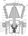
- FIG. 5 shows an embodiment of a gyratory crusher 500 which includes substantially the same features as the cone crusher 10, 400 of Figures 1 and 4 and accordingly, similar parts will be indicated with the same reference numerals.
- the frusto-conical housing 12 is inverted so that the opening 20 has its widest part is at the top and the narrowest part at the bottom.
- the lid 18 rests on the housing 12 and is arranged to provide a fulcrum for the shaft 26 at pivot 106.
- the shaft 26 has a spherically curved base that is supported on spherical bearing 34.
- the drive mechanism 46 pulls on shaft 26 so that crushing head 24 gyrates on bearing 34 around pivot 106 and crushes ore between the outer crushing shell 22 and the inner crushing shell 28.
- Bearing 34 is mounted on an adjustment piston 108 that can be raised or lowered in a conventional manner to thereby raise or lower shaft 26 and crushing head 24 within the housing 12 to adjust the operational width of the crushing gap 32.
- the further operation of the drive mechanism 46 will be the same as described above in relation to Figures 1 to 4 .
- the tie rods 62 can be provided in any other form that will allow the piston rods 54 to be pivotally joined to the coupling 64.
- the tie rods 62 can be hinge connected to both the piston rods 54 and the coupling 54.
- the tie rods can have end fittings in the form of ball joints as are found on link arms of a three-point hitch for being mounted on a pin.
- each of the drive units is a suitable mechanical or electric drive units such as a linear motor or solenoid.
- each drive unit will have an actuator being joined to the tie rods 62.
Landscapes
- Engineering & Computer Science (AREA)
- Food Science & Technology (AREA)
- Mechanical Engineering (AREA)
- Crushing And Grinding (AREA)
- Disintegrating Or Milling (AREA)
Claims (17)
- Brecher zum Zerkleinern von Material in feinere Partikel, wobei der Brecher (10) ein Gehäuse (12) umfasst, das eine äußere Brechschale (22) trägt; einen Brechkopf (24), der sich innerhalb des Gehäuses befindet und auf einer Welle (26) montiert ist, wobei der Brechkopf eine innere Brechschale (28) trägt, die mit der äußeren Brechschale zusammenwirkt, um einen Brechspalt (32) dazwischen zu bilden, dadurch gekennzeichnet, dasseine Kupplung (64) auf der Welle (26) montiert ist, wobei die Kupplung (64) um die Welle (26) drehbar ist, undein Antriebsmechanismus (46), der mindestens drei Antriebseinheiten (48, 50) umfasst, über eine Zugstange mit der Kupplung (64) verbunden ist und dazu ausgebildet ist, eine Bewegung der inneren Brechschale (28) relativ zur äußeren Brechschale (22) zu erzeugen.
- Brecher nach Anspruch 1, wobei der Antriebsmechanismus (46) so konfiguriert ist, dass er eine Bewegung des Brechkopfs (24) erzeugt, indem er nur eine Zugkraft auf die Welle (26) ausübt.
- Brecher nach Anspruch 1 oder 2, wobei die Antriebseinheiten (48, 50) so konfiguriert sind, dass sie selektiv aktiviert werden, um eine Bewegung des Brechkopfes (24) relativ zum Gehäuse (12) zu erzeugen.
- Brecher nach einem der Ansprüche 1 bis 3, wobei die Antriebseinheiten (48, 50) innerhalb des Gehäuses (12) angeordnet sind.
- Brecher nach einem der Ansprüche 1 bis 4, mit einem auf der Welle (26) montierten Gegengewicht (66), wobei das Gegengewicht vom Brechkopf (24) beabstandet ist und wobei die Antriebseinheiten (48, 50) mit der Welle zwischen dem Brechkopf und dem Gegengewicht verbunden sind.
- Brecher nach einem der Ansprüche 1 bis 5, wobei es sich bei jeder der Antriebseinheiten (48, 50) um Hydraulikzylinder (48) handelt und der Antriebsmechanismus (46) einen Hydraulikkreis (70) umfasst, der so konfiguriert ist, dass er jeden der Zylinder selektiv aktiviert.
- Brecher nach Anspruch 6, bei dem der Hydraulikkreis (70) zur Einstellung des Drucks der Hydraulikflüssigkeit in den Zylindern (48) betätigt werden kann, um dadurch einen gewünschten Betriebsbrechdruck auszuwählen, der vom Brechkopf (24) während des Betriebs ausgeübt werden soll.
- Brecher nach Anspruch 6 oder 7, wobei der Hydraulikkreislauf (70) betreibbar ist, um das Volumen der Hydraulikflüssigkeit in den Zylindern (48) einzustellen und dadurch eine gewünschte Betriebsbreite des Brechspalts (32) während des Betriebs zu wählen.
- Brecher nach einem der Ansprüche 1 bis 8, der ferner einen Positionserfassungsmechanismus umfasst, der so konfiguriert ist, dass er eine Betriebsposition des Brechkopfes (24) innerhalb des Gehäuses (12) bestimmt.
- Brecher nach Anspruch 9, wobei der Positionserfassungsmechanismus Folgendes umfasst: (a) jede Antriebseinheit ist eine positionserfassende Antriebseinheit, die so konfiguriert ist, dass sie eine Position ihres Stellglieds erfasst; (b) ein Näherungssensor ist mit jeder Antriebseinheit verbunden, wobei die Näherungssensoren so konfiguriert sind, dass sie die Nähe der Welle zu ihren zugehörigen Antriebseinheiten erfassen; und (c) ein Winkelsensor ist so konfiguriert, dass er die Winkelposition und Ausrichtung der Welle innerhalb des Gehäuses erfasst.
- Brecher nach einem der Ansprüche 1 bis 10, wobei der Brecher (10) ein Kegelbrecher oder ein Kreiselbrecher ist.
- Verfahren zum Betreiben eines Brechers (10) mit einem Gehäuse (12), das eine äußere Brechschale (22) trägt, und ferner mit einem Brechkopf (24), der innerhalb des Gehäuses angeordnet und auf einer Welle (26) montiert ist, wobei der Brechkopf eine innere Brechschale (28) trägt, die mit der äußeren Brechschale zusammenwirkt, um einen Brechspalt (32) dazwischen zu bilden, dadurch gekennzeichnet, dass das Verfahrenumfasst das Bereitstellen einer Kupplung (64), die auf der Welle (26) montiert ist, wobei die Kupplung (64) in der Lage ist, sich um die Welle (26) zu drehen,und Verbinden eines Antriebsmechanismus (46), der mindestens drei Antriebseinheiten (48, 50) umfasst, über eine Zugstange mit der Kupplung (64), um eine Bewegung der inneren Brecherschale (28) relativ zur äußeren Brecherschale (22) zu erzeugen.
- Verfahren nach Anspruch 12, das den Schritt umfasst, dass der Antriebsmechanismus (46) eine Bewegung des Brechkopfes (24) erzeugt, indem er nur eine Zugkraft auf die Welle (26) ausübt.
- Verfahren nach Anspruch 12 oder 13, das den Schritt des selektiven Aktivierens jeder der Antriebseinheiten (48, 50) zur Erzeugung einer Bewegung des Brechkopfes (24) relativ zum Gehäuse (12) umfasst.
- Verfahren nach einem der Ansprüche 12 bis 14, wobei der Brechkopf (24) auf einem Lager (34) gelagert ist und jede der Antriebseinheiten (48, 50) Hydraulikzylinder (48) sind, die durch einen hydraulischen Antriebsmechanismus (46) betätigt werden können, und wobei das Verfahren den Schritt des Ausstoßens eines Teils der im hydraulischen Antriebsmechanismus (46) verwendeten Hydraulikflüssigkeit zwischen das Lager (34) und den Brechkopf (24) umfasst.
- Verfahren nach Anspruch 15, das den Schritt des Einstellens eines Drucks der im hydraulischen Antriebsmechanismus (46) verwendeten Hydraulikflüssigkeit umfasst, um dadurch einen gewünschten Brechdruck auszuwählen, der vom Brechkopf (24) ausgeübt werden soll.
- Verfahren nach Anspruch 15 oder 16, wobei jeder Zylinder (48) einen Kolben (50) umfasst, der zwischen einer inneren Position proximal zu der Welle (26) und einer äußeren Position distal zu der Welle (26) hin- und herbewegt werden kann, und wobei das Verfahren die Schritte des selektiven Aktivierens und Deaktivierens jedes der Zylinder (48) umfasst, um eine orbitale oder kreisförmige Bewegung des Brechkopfes (24) relativ zu dem äußeren Brechgehäuse (22) zu erzeugen, wobei jeder Zylinder (48) aktiviert wird, während sich sein Kolben (50) von seiner inneren Position zu seiner äußeren Position bewegt, und jeder Zylinder (48) deaktiviert wird, während sich sein Kolben (50) von seiner äußeren Position zu seiner inneren Position bewegt.
Applications Claiming Priority (3)
| Application Number | Priority Date | Filing Date | Title |
|---|---|---|---|
| AU2019900949A AU2019900949A0 (en) | 2019-03-21 | Crusher | |
| AU2019902211A AU2019902211A0 (en) | 2019-06-25 | Crusher | |
| PCT/AU2020/050207 WO2020186288A1 (en) | 2019-03-21 | 2020-03-05 | Crusher |
Publications (4)
| Publication Number | Publication Date |
|---|---|
| EP3941635A1 EP3941635A1 (de) | 2022-01-26 |
| EP3941635A4 EP3941635A4 (de) | 2023-01-11 |
| EP3941635B1 true EP3941635B1 (de) | 2025-01-15 |
| EP3941635C0 EP3941635C0 (de) | 2025-01-15 |
Family
ID=72518880
Family Applications (1)
| Application Number | Title | Priority Date | Filing Date |
|---|---|---|---|
| EP20773700.8A Active EP3941635B1 (de) | 2019-03-21 | 2020-03-05 | Zerkleinerer |
Country Status (9)
| Country | Link |
|---|---|
| US (1) | US12083530B2 (de) |
| EP (1) | EP3941635B1 (de) |
| CN (1) | CN113613789A (de) |
| AU (1) | AU2020242915B2 (de) |
| CA (1) | CA3132397A1 (de) |
| CL (1) | CL2021002424A1 (de) |
| MX (1) | MX2021011399A (de) |
| WO (1) | WO2020186288A1 (de) |
| ZA (1) | ZA202106512B (de) |
Families Citing this family (5)
| Publication number | Priority date | Publication date | Assignee | Title |
|---|---|---|---|---|
| AU2021253250A1 (en) * | 2020-04-08 | 2022-10-06 | Jeffrey Victor Belke | Drive mechanism for a crusher |
| CN115301324B (zh) * | 2022-08-23 | 2023-11-24 | 吉林大学 | 一种粒径动态感知的智能碎土分级筛选机构 |
| WO2024150116A1 (en) * | 2023-01-09 | 2024-07-18 | Flsmidth A/S | Device for crushing rock and assembly method |
| BE1031244B1 (de) * | 2023-01-09 | 2024-08-06 | Smidth As F L | Vorrichtung zum Brechen von Gestein und Montageverfahren |
| CN119633935B (zh) * | 2025-02-18 | 2025-07-11 | 曾志无废城市(三明)环保科技有限公司 | 一种生活垃圾焚烧炉渣的再破碎机构、其破碎装置及控制方法 |
Family Cites Families (17)
| Publication number | Priority date | Publication date | Assignee | Title |
|---|---|---|---|---|
| US857940A (en) | 1906-06-13 | 1907-06-25 | Edward A Hoff | Rock-crusher. |
| DE1157459B (de) | 1955-06-13 | 1963-11-14 | Esch Werke K G Maschinenfabrik | Hydraulischer Antrieb zur Erzeugung kreisender, translatorischer Bewegungen des Brechkoerpers von Kreiselbrechern |
| GB786258A (en) | 1955-06-14 | 1957-11-13 | Westfalia Dinnendahl Groeppel | Improvements in gyratory cone crushers |
| US3666188A (en) * | 1969-08-19 | 1972-05-30 | Hewitt Robins Inc | Gyratory crusher |
| US4615491A (en) * | 1979-10-15 | 1986-10-07 | Telsmith Division Barber-Greene Company | Gyratory crusher with automatic tramp iron release |
| FI991388A0 (fi) | 1999-06-17 | 1999-06-17 | Lohja Rudus Oy Ab | Karamurskain |
| FI20010867L (fi) * | 2001-04-25 | 2002-10-26 | Feracitas Oy | Murskain |
| GB0327204D0 (en) | 2003-11-22 | 2003-12-24 | Extec Screens & Crushers Ltd | Gyratory crusher |
| GB0407504D0 (en) * | 2004-04-02 | 2004-05-05 | Extec Screens & Crushers Ltd | Cone crusher drive |
| RU109021U1 (ru) | 2007-06-15 | 2011-10-10 | Сандвик Интеллекчуал Проперти Аб | Дробильная установка |
| SE533935C2 (sv) | 2009-07-07 | 2011-03-08 | Sandvik Intellectual Property | Gyratorisk kross |
| CN102327791A (zh) | 2011-10-10 | 2012-01-25 | 来军剑 | 圆锥式破碎机 |
| EP2881176B1 (de) * | 2013-12-09 | 2016-03-16 | Sandvik Intellectual Property AB | Kegelbrecher-Wellenpositionsmessungs-Sensoranordnung |
| RU2587704C1 (ru) * | 2015-03-13 | 2016-06-20 | Константин Евсеевич Белоцерковский | Конусная инерционная дробилка с модернизированным приводом |
| CN106694093A (zh) | 2016-11-30 | 2017-05-24 | 河池市技术开发中心 | 一种液压圆锥破碎机的液压油缸使用方法 |
| CN207102703U (zh) * | 2017-07-11 | 2018-03-16 | 北京凯特破碎机有限公司 | 一种惯性圆锥破碎机空腔保护装置 |
| CN107457028A (zh) | 2017-08-31 | 2017-12-12 | 燕山大学 | 一种惯性圆锥破碎机及其平衡方法 |
-
2020
- 2020-03-05 MX MX2021011399A patent/MX2021011399A/es unknown
- 2020-03-05 EP EP20773700.8A patent/EP3941635B1/de active Active
- 2020-03-05 AU AU2020242915A patent/AU2020242915B2/en active Active
- 2020-03-05 CN CN202080023135.3A patent/CN113613789A/zh active Pending
- 2020-03-05 CA CA3132397A patent/CA3132397A1/en active Pending
- 2020-03-05 US US17/439,529 patent/US12083530B2/en active Active
- 2020-03-05 WO PCT/AU2020/050207 patent/WO2020186288A1/en not_active Ceased
-
2021
- 2021-09-06 ZA ZA2021/06512A patent/ZA202106512B/en unknown
- 2021-09-16 CL CL2021002424A patent/CL2021002424A1/es unknown
Also Published As
| Publication number | Publication date |
|---|---|
| EP3941635A4 (de) | 2023-01-11 |
| CL2021002424A1 (es) | 2022-08-05 |
| MX2021011399A (es) | 2021-10-13 |
| US20220152617A1 (en) | 2022-05-19 |
| ZA202106512B (en) | 2022-08-31 |
| CA3132397A1 (en) | 2020-09-24 |
| AU2020242915A1 (en) | 2021-10-28 |
| AU2020242915B2 (en) | 2025-02-20 |
| US12083530B2 (en) | 2024-09-10 |
| EP3941635C0 (de) | 2025-01-15 |
| CN113613789A (zh) | 2021-11-05 |
| EP3941635A1 (de) | 2022-01-26 |
| WO2020186288A1 (en) | 2020-09-24 |
Similar Documents
| Publication | Publication Date | Title |
|---|---|---|
| EP3941635B1 (de) | Zerkleinerer | |
| US5803382A (en) | Gyratory crusher having corrugation-like-seal | |
| CA1206941A (en) | Conical crusher | |
| CA1084467A (en) | Hydraulically loaded pulverizer journal | |
| US2791383A (en) | Hydraulic control for gyratory crusher | |
| US2909330A (en) | Pulverizing mill and process of pulverizing material | |
| AU2011274606A1 (en) | Gyratory crusher having a sealing arrangement | |
| CN108465541B (zh) | 宠物食品原料研磨装置 | |
| NZ522105A (en) | Method for monitoring condition of bearings of a crusher, and a crusher with friction force sensing | |
| CN107469909A (zh) | 多自由度并联机构智能破碎机 | |
| US5927623A (en) | Gyratory crusher with automatic control system | |
| CN207307945U (zh) | 多自由度并联机构智能破碎机 | |
| US2579516A (en) | Gyratory crushfr with vertically adjustable head | |
| US5971306A (en) | Gyratory crusher having tramp iron relief system with an annular hydraulic manifold | |
| AU688421B2 (en) | Cone crusher having inclined hold-down cylinders | |
| JP6261586B2 (ja) | 粉砕装置 | |
| RU2792188C1 (ru) | Дробильная машина | |
| US4147309A (en) | Hydroset pressure relief system | |
| US2908448A (en) | Gyratory crusher | |
| CN101080277B (zh) | 具有用于调节夹爪间空间的系统的锥形破碎机 | |
| US5875981A (en) | Gyratory crusher having tramp iron relief system | |
| US3481548A (en) | Gyratory crusher with resilient mounting of the crusher cone | |
| DK165577B (da) | Fremgangsmaade og centrifugalmoelle til maling af faste partikler | |
| CN115335151B (zh) | 破碎机、操作破碎机的方法和用于破碎机的密封件 | |
| JP6146876B2 (ja) | ハンマー装置 |
Legal Events
| Date | Code | Title | Description |
|---|---|---|---|
| STAA | Information on the status of an ep patent application or granted ep patent |
Free format text: STATUS: THE INTERNATIONAL PUBLICATION HAS BEEN MADE |
|
| PUAI | Public reference made under article 153(3) epc to a published international application that has entered the european phase |
Free format text: ORIGINAL CODE: 0009012 |
|
| STAA | Information on the status of an ep patent application or granted ep patent |
Free format text: STATUS: REQUEST FOR EXAMINATION WAS MADE |
|
| 17P | Request for examination filed |
Effective date: 20210924 |
|
| AK | Designated contracting states |
Kind code of ref document: A1 Designated state(s): AL AT BE BG CH CY CZ DE DK EE ES FI FR GB GR HR HU IE IS IT LI LT LU LV MC MK MT NL NO PL PT RO RS SE SI SK SM TR |
|
| DAV | Request for validation of the european patent (deleted) | ||
| DAX | Request for extension of the european patent (deleted) | ||
| A4 | Supplementary search report drawn up and despatched |
Effective date: 20221209 |
|
| RIC1 | Information provided on ipc code assigned before grant |
Ipc: B02C 25/00 20060101ALI20221205BHEP Ipc: B02C 2/04 20060101ALI20221205BHEP Ipc: B02C 2/02 20060101AFI20221205BHEP |
|
| GRAP | Despatch of communication of intention to grant a patent |
Free format text: ORIGINAL CODE: EPIDOSNIGR1 |
|
| STAA | Information on the status of an ep patent application or granted ep patent |
Free format text: STATUS: GRANT OF PATENT IS INTENDED |
|
| INTG | Intention to grant announced |
Effective date: 20240918 |
|
| GRAS | Grant fee paid |
Free format text: ORIGINAL CODE: EPIDOSNIGR3 |
|
| GRAA | (expected) grant |
Free format text: ORIGINAL CODE: 0009210 |
|
| STAA | Information on the status of an ep patent application or granted ep patent |
Free format text: STATUS: THE PATENT HAS BEEN GRANTED |
|
| AK | Designated contracting states |
Kind code of ref document: B1 Designated state(s): AL AT BE BG CH CY CZ DE DK EE ES FI FR GB GR HR HU IE IS IT LI LT LU LV MC MK MT NL NO PL PT RO RS SE SI SK SM TR |
|
| REG | Reference to a national code |
Ref country code: CH Ref legal event code: EP Ref country code: GB Ref legal event code: FG4D |
|
| REG | Reference to a national code |
Ref country code: IE Ref legal event code: FG4D |
|
| REG | Reference to a national code |
Ref country code: DE Ref legal event code: R096 Ref document number: 602020044849 Country of ref document: DE |
|
| U01 | Request for unitary effect filed |
Effective date: 20250115 |
|
| U07 | Unitary effect registered |
Designated state(s): AT BE BG DE DK EE FI FR IT LT LU LV MT NL PT RO SE SI Effective date: 20250121 |
|
| U20 | Renewal fee for the european patent with unitary effect paid |
Year of fee payment: 6 Effective date: 20250119 |
|
| PG25 | Lapsed in a contracting state [announced via postgrant information from national office to epo] |
Ref country code: RS Free format text: LAPSE BECAUSE OF FAILURE TO SUBMIT A TRANSLATION OF THE DESCRIPTION OR TO PAY THE FEE WITHIN THE PRESCRIBED TIME-LIMIT Effective date: 20250415 |
|
| PG25 | Lapsed in a contracting state [announced via postgrant information from national office to epo] |
Ref country code: PL Free format text: LAPSE BECAUSE OF FAILURE TO SUBMIT A TRANSLATION OF THE DESCRIPTION OR TO PAY THE FEE WITHIN THE PRESCRIBED TIME-LIMIT Effective date: 20250115 |
|
| PG25 | Lapsed in a contracting state [announced via postgrant information from national office to epo] |
Ref country code: ES Free format text: LAPSE BECAUSE OF FAILURE TO SUBMIT A TRANSLATION OF THE DESCRIPTION OR TO PAY THE FEE WITHIN THE PRESCRIBED TIME-LIMIT Effective date: 20250115 |
|
| PG25 | Lapsed in a contracting state [announced via postgrant information from national office to epo] |
Ref country code: IS Free format text: LAPSE BECAUSE OF FAILURE TO SUBMIT A TRANSLATION OF THE DESCRIPTION OR TO PAY THE FEE WITHIN THE PRESCRIBED TIME-LIMIT Effective date: 20250515 Ref country code: NO Free format text: LAPSE BECAUSE OF FAILURE TO SUBMIT A TRANSLATION OF THE DESCRIPTION OR TO PAY THE FEE WITHIN THE PRESCRIBED TIME-LIMIT Effective date: 20250415 |
|
| PG25 | Lapsed in a contracting state [announced via postgrant information from national office to epo] |
Ref country code: HR Free format text: LAPSE BECAUSE OF FAILURE TO SUBMIT A TRANSLATION OF THE DESCRIPTION OR TO PAY THE FEE WITHIN THE PRESCRIBED TIME-LIMIT Effective date: 20250115 |
|
| PG25 | Lapsed in a contracting state [announced via postgrant information from national office to epo] |
Ref country code: GR Free format text: LAPSE BECAUSE OF FAILURE TO SUBMIT A TRANSLATION OF THE DESCRIPTION OR TO PAY THE FEE WITHIN THE PRESCRIBED TIME-LIMIT Effective date: 20250416 |
|
| PG25 | Lapsed in a contracting state [announced via postgrant information from national office to epo] |
Ref country code: SM Free format text: LAPSE BECAUSE OF FAILURE TO SUBMIT A TRANSLATION OF THE DESCRIPTION OR TO PAY THE FEE WITHIN THE PRESCRIBED TIME-LIMIT Effective date: 20250115 |
|
| PG25 | Lapsed in a contracting state [announced via postgrant information from national office to epo] |
Ref country code: MC Free format text: LAPSE BECAUSE OF FAILURE TO SUBMIT A TRANSLATION OF THE DESCRIPTION OR TO PAY THE FEE WITHIN THE PRESCRIBED TIME-LIMIT Effective date: 20250115 |
|
| PG25 | Lapsed in a contracting state [announced via postgrant information from national office to epo] |
Ref country code: CZ Free format text: LAPSE BECAUSE OF FAILURE TO SUBMIT A TRANSLATION OF THE DESCRIPTION OR TO PAY THE FEE WITHIN THE PRESCRIBED TIME-LIMIT Effective date: 20250115 |
|
| REG | Reference to a national code |
Ref country code: CH Ref legal event code: H13 Free format text: ST27 STATUS EVENT CODE: U-0-0-H10-H13 (AS PROVIDED BY THE NATIONAL OFFICE) Effective date: 20251023 |
|
| PG25 | Lapsed in a contracting state [announced via postgrant information from national office to epo] |
Ref country code: SK Free format text: LAPSE BECAUSE OF FAILURE TO SUBMIT A TRANSLATION OF THE DESCRIPTION OR TO PAY THE FEE WITHIN THE PRESCRIBED TIME-LIMIT Effective date: 20250115 |
|
| PLBE | No opposition filed within time limit |
Free format text: ORIGINAL CODE: 0009261 |
|
| STAA | Information on the status of an ep patent application or granted ep patent |
Free format text: STATUS: NO OPPOSITION FILED WITHIN TIME LIMIT |
|
| 26N | No opposition filed |
Effective date: 20251016 |
|
| GBPC | Gb: european patent ceased through non-payment of renewal fee |
Effective date: 20250415 |
|
| PG25 | Lapsed in a contracting state [announced via postgrant information from national office to epo] |
Ref country code: GB Free format text: LAPSE BECAUSE OF NON-PAYMENT OF DUE FEES Effective date: 20250415 |
|
| PG25 | Lapsed in a contracting state [announced via postgrant information from national office to epo] |
Ref country code: CH Free format text: LAPSE BECAUSE OF NON-PAYMENT OF DUE FEES Effective date: 20250331 |
|
| PG25 | Lapsed in a contracting state [announced via postgrant information from national office to epo] |
Ref country code: IE Free format text: LAPSE BECAUSE OF NON-PAYMENT OF DUE FEES Effective date: 20250305 |