EP3941297B1 - Schuhwerk mit zonalem polstersystem - Google Patents
Schuhwerk mit zonalem polstersystem Download PDFInfo
- Publication number
- EP3941297B1 EP3941297B1 EP20719858.1A EP20719858A EP3941297B1 EP 3941297 B1 EP3941297 B1 EP 3941297B1 EP 20719858 A EP20719858 A EP 20719858A EP 3941297 B1 EP3941297 B1 EP 3941297B1
- Authority
- EP
- European Patent Office
- Prior art keywords
- fluid
- filled chamber
- forefoot
- sole structure
- midfoot
- Prior art date
- Legal status (The legal status is an assumption and is not a legal conclusion. Google has not performed a legal analysis and makes no representation as to the accuracy of the status listed.)
- Active
Links
Images


Classifications
-
- A—HUMAN NECESSITIES
- A43—FOOTWEAR
- A43B—CHARACTERISTIC FEATURES OF FOOTWEAR; PARTS OF FOOTWEAR
- A43B13/00—Soles; Sole-and-heel integral units
- A43B13/02—Soles; Sole-and-heel integral units characterised by the material
- A43B13/12—Soles with several layers of different materials
- A43B13/125—Soles with several layers of different materials characterised by the midsole or middle layer
- A43B13/127—Soles with several layers of different materials characterised by the midsole or middle layer the midsole being multilayer
-
- A—HUMAN NECESSITIES
- A43—FOOTWEAR
- A43B—CHARACTERISTIC FEATURES OF FOOTWEAR; PARTS OF FOOTWEAR
- A43B13/00—Soles; Sole-and-heel integral units
- A43B13/14—Soles; Sole-and-heel integral units characterised by the constructive form
- A43B13/18—Resilient soles
- A43B13/187—Resiliency achieved by the features of the material, e.g. foam, non liquid materials
- A43B13/188—Differential cushioning regions
-
- A—HUMAN NECESSITIES
- A43—FOOTWEAR
- A43B—CHARACTERISTIC FEATURES OF FOOTWEAR; PARTS OF FOOTWEAR
- A43B13/00—Soles; Sole-and-heel integral units
- A43B13/14—Soles; Sole-and-heel integral units characterised by the constructive form
- A43B13/141—Soles; Sole-and-heel integral units characterised by the constructive form with a part of the sole being flexible, e.g. permitting articulation or torsion
-
- A—HUMAN NECESSITIES
- A43—FOOTWEAR
- A43B—CHARACTERISTIC FEATURES OF FOOTWEAR; PARTS OF FOOTWEAR
- A43B13/00—Soles; Sole-and-heel integral units
- A43B13/14—Soles; Sole-and-heel integral units characterised by the constructive form
- A43B13/18—Resilient soles
- A43B13/181—Resiliency achieved by the structure of the sole
- A43B13/186—Differential cushioning region, e.g. cushioning located under the ball of the foot
-
- A—HUMAN NECESSITIES
- A43—FOOTWEAR
- A43B—CHARACTERISTIC FEATURES OF FOOTWEAR; PARTS OF FOOTWEAR
- A43B13/00—Soles; Sole-and-heel integral units
- A43B13/14—Soles; Sole-and-heel integral units characterised by the constructive form
- A43B13/18—Resilient soles
- A43B13/189—Resilient soles filled with a non-compressible fluid, e.g. gel, water
-
- A—HUMAN NECESSITIES
- A43—FOOTWEAR
- A43B—CHARACTERISTIC FEATURES OF FOOTWEAR; PARTS OF FOOTWEAR
- A43B13/00—Soles; Sole-and-heel integral units
- A43B13/14—Soles; Sole-and-heel integral units characterised by the constructive form
- A43B13/18—Resilient soles
- A43B13/20—Pneumatic soles filled with a compressible fluid, e.g. air, gas
-
- A—HUMAN NECESSITIES
- A43—FOOTWEAR
- A43B—CHARACTERISTIC FEATURES OF FOOTWEAR; PARTS OF FOOTWEAR
- A43B13/00—Soles; Sole-and-heel integral units
- A43B13/02—Soles; Sole-and-heel integral units characterised by the material
- A43B13/04—Plastics, rubber or vulcanised fibre
-
- A—HUMAN NECESSITIES
- A43—FOOTWEAR
- A43B—CHARACTERISTIC FEATURES OF FOOTWEAR; PARTS OF FOOTWEAR
- A43B13/00—Soles; Sole-and-heel integral units
- A43B13/14—Soles; Sole-and-heel integral units characterised by the constructive form
- A43B13/18—Resilient soles
- A43B13/181—Resiliency achieved by the structure of the sole
- A43B13/183—Leaf springs
Definitions
- the present disclosure relates to an article of footwear and more particularly to a sole structure for an article of footwear.
- Conventional articles of athletic footwear include two primary elements, an upper and a sole structure.
- the upper provides a covering for the foot that securely receives and positions the foot with respect to the sole structure.
- the upper may have a configuration that protects the foot and provides ventilation, thereby cooling the foot and removing perspiration.
- the sole structure is secured to a lower surface of the upper and is generally positioned between the foot and the ground.
- the sole structure may provide traction and control potentially harmful foot motion, such as over pronation. Accordingly, the upper and the sole structure operate cooperatively to provide a comfortable structure that is suited for a wide variety of ambulatory activities, such as walking and running.
- the sole structure generally incorporates multiple layers that are conventionally referred to as an insole, a midsole, and an outsole.
- the insole is a thin, cushioning member located within the upper and adjacent the plantar (lower) surface of the foot to enhance footwear comfort.
- the midsole which is traditionally attached to the upper along the entire length of the upper, forms the middle layer of the sole structure and serves a variety of purposes that include controlling foot motions and providing cushioning.
- the outsole forms the ground-contacting element of footwear and is usually fashioned from a durable, wear-resistant material that includes texturing to improve traction.
- the primary element of a conventional midsole is a resilient, polymer foam material, such as polyurethane or ethylvinylacetate, that extends throughout the length of the footwear.
- the properties of the polymer foam material in the midsole are primarily dependent upon factors that include the dimensional configuration of the midsole and the specific characteristics of the material selected for the polymer foam, including the density of the polymer foam material. By varying these factors throughout the midsole, the relative stiffness, degree of ground reaction force attenuation, and energy absorption properties may be altered to meet the specific demands of the activity for which the footwear is intended to be used.
- WO 2016/144538 A1 teaches a sole structure with a fluid filled chamber.
- the invention is defined by a sole structure as in claim 1 and by an article of footwear as in claim 2. Preferred embodiments are defined in the dependent claims.
- a sole structure for an article of footwear includes a midsole formed of a foamed polymer, a ground contacting outsole surface, and a cushioning system disposed between the midsole and the ground contacting outsole surface.
- the cushioning system includes a polymeric plate defining an upper plate and a lower plate provided in a spaced relationship.
- the upper plate and lower plate are integrally connected at a posterior portion of the sole structure.
- At least two vertically stacked fluid-filled chambers are provided between the upper plate and the lower plate within the midfoot region of the cushioning system.
- the at least two vertically stacked fluid-filled chambers include a first midfoot fluid-filled chamber coupled to the upper plate, and a second midfoot fluid-filled chamber coupled to and between the first midfoot fluid-filled chamber and the lower plate.
- the cushioning system further includes at least two laterally arranged fluid-filled chambers provided between the upper plate and the lower plate within the midfoot region of the cushioning system.
- the at least two laterally arranged fluid-filled chambers include a lateral forefoot fluid-filled chamber and a medial forefoot fluid-filled chamber.
- the lateral forefoot fluid-filled chamber is positioned between a lateral edge of the sole structure and the medial forefoot fluid-filled chamber
- the medial forefoot fluid-filled chamber is positioned between a medial edge of the sole structure and the lateral forefoot fluid-filled chamber.
- the following discussion and accompanying figures disclose an article of footwear 10 (also referred to as the article 10) in accordance with the present invention.
- the article 10 is depicted in the figures and discussed below as having a configuration that is suitable for athletic activities, particularly running.
- the concepts disclosed with respect to the article 10 may, however, be applied to footwear styles that are specifically designed for a wide range of other athletic activities, including basketball, baseball, football, soccer, walking, and hiking, for example, and may also be applied to various non-athletic footwear styles. Accordingly, one skilled in the relevant art will recognize that the concepts disclosed herein may be applied to a wide range of footwear styles and are not limited to the specific embodiments discussed below and depicted in the figures.
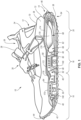
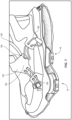
- an article of footwear 10 is depicted that includes an upper 12 and a sole structure 14 attached to the upper 12.
- the article of footwear 10 may be divided into one or more regions.
- the regions may include a forefoot region 16, a midfoot region 18, and a heel region 20.
- the forefoot region 16 may correspond with toes and joints connecting metatarsal bones with phalanx bones of a foot.
- the midfoot region 18 may correspond with an arch area of the foot while the heel region 18 may correspond with rear portions of the foot, including a calcaneus bone.
- the article of footwear 10 may additionally include a medial side 22 (shown in FIG. 2 ) and a lateral side 24 (shown in FIG. 1 ) that correspond with opposite sides of the article of footwear 10 and extend through the regions 16, 18, 20.
- the upper 12 includes interior surfaces that defines an interior void 26 that receives and secures a foot for support on the sole structure 14.
- An ankle opening 28 in the heel region 20 may provide access to the interior void 26.
- the ankle opening 28 may receive a foot to secure the foot within the void 26 and facilitate entry and removal of the foot from and to the interior void 26.
- one or more fasteners or other closure systems 30 extend across the upper 12 to adjust a fit of the interior void 26 around the foot while concurrently accommodating entry and removal of the foot therefrom.
- the fasteners or other closure systems 30 may include laces, straps, cords, latching mechanisms, clasps, snaps, hook-and-loop, or any other suitable type of fastener.
- the upper 12 may be formed from one or more materials that are stitched or adhesively bonded together to form the interior void 26.
- Suitable materials of the upper 12 may include, textiles, foam, leather, and synthetic leather. The materials may be selected and located to impart properties of durability, air-permeability, wear-resistance, flexibility, and comfort to the foot while disposed within the interior void 26
- the sole structure 14 is attached to an underside of the upper 12 and provides the article of footwear 10 with support and cushioning during use. Namely, the sole structure 14 attenuates ground reaction forces caused by the article of footwear 10 striking the ground during use. Accordingly, and as set forth below, the sole structure 14 may incorporate one or more materials having energy absorbing characteristics to allow the sole structure 14 to minimize the impact experienced by a user when wearing the article of footwear 10.
- the sole structure 14 may include a midsole 36, an outsole 38, and one or more cushioning systems 40 disposed generally between the midsole 36 and the outsole 38.
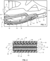
- the cushioning system 40 may include a plate 42 that extends generally between an anterior end 44 of the article of footwear 10 and a posterior end 46, and one or more fluid-filled chambers 48. As will be described in greater detail below, the plate 42 and one or more fluid-filled chambers 48 may work in conjunction to further attenuate ground reaction forces.
- the midsole 36 is shown as extending from the proximate the anterior end 44 of the article of footwear 10 to proximate the posterior end 46 and beyond the anterior and posterior extremes of the upper 12.
- the midsole 36 is secured to a lower portion of upper 12, and is positioned to extend under the foot during use.
- midsole 36 attenuates ground reaction forces and absorbs energy (i.e., imparts cushioning) when walking or running, for example.
- the midsole 36 may be formed from an energy absorbing material such as, for example, polymer foam. Forming the midsole 36 from an energy-absorbing material, such as for example, an ethylvinylacetate foam allows the midsole 36 to attenuate ground-reaction forces caused by movement of the article of footwear 10 over ground during use.
- An outsole 38 or outsole surface is provided on a lower, ground-facing surface of the cushioning system 40, and on an opposite side of the cushioning system 40 from the midsole 36 and upper 12.
- the outsole 38 may define a ground-engaging surface 50 that is operative to provide wear-resistance and to enhance traction between the article of footwear 12 and the ground.
- the outsole 38 may be formed from a resilient material such as, for example, rubber, which can improve traction and durability.
- the ground-engaging surface 50 may include one or more traction elements 52 that extend outward to provide the article of footwear 10 with increased traction during use.
- the midsole 36 may serve to attach the cushioning system 40 to the upper 12.
- the cushioning system 40 may be coupled to the midsole 36, for example, by adhering a portion of the plate 42 to a lower surface of the midsole 36 (i.e., via a suitable adhesive - not shown).
- the cushioning system 40 may be attached to the midsole 36 by molding a material of the midsole 36 directly to the plate 42.
- the plate 42 may be disposed within a cavity of a mold (not shown) used to form the midsole 36. Accordingly, when the midsole 36 is formed (i.e. by foaming a polymer material), the material of the midsole 36 is joined to the material of the plate 42, thereby forming a unitary structure having both the midsole 36 and the plate 42.
- the cushioning system 40 is described and shown as being attached to an underside of the midsole 36 (i.e., on an opposite side of the midsole from the upper 12), a portion of the cushioning system 40 could altematively be embedded within the material of the midsole 36.
- a portion of the plate 42 may be encapsulated by the midsole 36 such that a portion of the midsole 36 extends through or to opposing sides of a portion of the plate 42.
- the plate 42 could be disposed within the midsole 36 but not be fully encapsulated.
- the plate 42 could be visible around a perimeter of the midsole 36 while a portion of the midsole 36 extends between the plate 42 and the upper 12 and another portion of the midsole 36 extends between the plate 42 and the outsole 38.
- the plate 42 may include an upper plate 60 that is integrally coupled with a lower plate 62 (i.e., at a joint/joint region 64) to form a spring-like shock absorber.
- the upper plate 60 and lower plate 62 are both cantilevered from the joint region 64 and are configured to deflect toward each other in response to a static or dynamic load applied by the wearer.
- the cushioning system 40 may further include one or more fluid-filled chambers 48 provided between the upper plate 60 and the lower plate 62 to aid in controlling the deflection magnitude and rate apart from the joint 64.
- the upper and lower plates 60, 62 may each extend along a longitudinal dimension of the sole structure 14, and in some embodiments one or both may fully extend from the anterior end 44 of the sole structure 14 to the posterior end 46 of the sole structure 14.
- the upper plate 60 may extend along at least a portion of the heel region 20 and midfoot region 18.
- the upper plate 60 may extend across at least a portion of the heel region 20, midfoot region 18, and forefoot region 16.
- the lower plate 62 may extend across at least a portion of the heel region 20, midfoot region 18, and forefoot region 16
- the plate 42 may be formed from a single sheet of a relatively rigid material that is folded/wrapped back on itself.
- the plate 42 may be formed from a non-foamed polymer material or, alternatively, from a composite material containing fibers such as carbon fibers. Suitable materials may include thermoplastic polyurethane (TPU), polyamides (e.g., PA6 or PA66), or other engineering polymers.
- the material may include a fiber fill, such as short or long fiber glass, aramid, bamboo, or carbon fibers, or may include similar continuous fabrics.
- Forming the plate 42 from a relatively rigid material allows the plate 42 to distribute forces associated with use of the article 10 while maintaining the upper plate 60 and lower plate 62 in a spaced relationship. In some embodiments, this spaced relationship is desirably greater than about 5 mm, or greater than about 8 mm, or even greater than about 10 mm.
- the joint region 64 of the plate 42 may be provided within, or posterior to the heel region 20 of the sole structure 14, and may be formed with a suitable thickness and stiffness to withstand expected static and impact loads without permitting the upper and lower plates 60, 62 to overly deflect and/or come into contact with each other.
- an intermediate recess/void 66 may exist between the upper and lower plates 60, 62 within the heel region 20. In an unloaded/relaxed state, this recess/void 66 may have a first height 68, measured normal to the ground. When worn, static and impact loads from the wearer may urge the upper and lower plates 60, 62 into a more closely spaced relationship. Said another way, the recess/void 66 may be compressed to have a second height that is less than the first height 68.
- the degree to which the plates 60, 62 are flex toward each other in the heel region 20 is largely controlled by the stiffness and location of the plate 42 within the joint region 64. While some elastic flexure/movement of the upper and lower plates 60, 62 is desirable to provide cushioning/force attenuation, if the joint region 64 is not sufficiently stiff, the deflection could be larger than desired, which could cause the shoe to feel unstable.
- the joint region 64 of the plate 42 may be provided rearward of the posterior end 70 of the upper 12 and/or rearward of a posterior end 72 of the midsole 36.
- the cushioning system 40 may rely on one or more fluid-filled chambers 48 to provide the cushioning response within the midfoot region 18 and/or within the forefoot region 16.
- the cushioning system 40 includes a first fluid-filled chamber 80 and a second fluid-filled chamber 82 provided within the midfoot region 18, and a fluid-filled chamber 84 provided in the forefoot region 16.
- the first fluid-filled chamber 80 is disposed generally between the upper plate 60 and the second fluid-filled chamber 82 while the second fluid-filled chamber 82 is disposed between the lower plate 62 and the first fluid-filled chamber 80.
- the first fluid-filled chamber 80 is attached to a lower surface of the upper plate 60 at a first side and is attached to the second fluid-filled chamber 82 at a second side.
- the second fluid-filled chamber 82 is attached at a first side to the upper surface of the lower plate 62 and is attached to the first fluid-filled chamber 80 at a second side.
- first fluid-filled chamber 80 may be attached to the second fluid-filled chamber 82 by melting the material of the first fluid-filled chamber 80 and the material of the second fluid-filled chamber 82 at a junction of the first fluid-filled chamber 80 and the second fluid-filled chamber 82 (e.g., similar to welding).
- the forefoot fluid-filled chamber 84 may be provided between the upper plate 60 and the lower plate 62.
- the forefoot fluid-filled chamber 84 is attached to a lower surface of the upper plate 60 at a first side and is attached to the upper surface of the lower plate 62 at a second side.
- the fluid-filled chambers 80, 82, 84 may be attached to one another and/or to the upper and lower plates 60, 62, respectively, via a suitable adhesive.
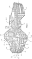
- the forefoot fluid chamber 84 may actually comprise two discrete fluid filled chambers: a medial forefoot fluid-filled chamber 86 and lateral forefoot fluid-filled chamber 88.
- the midfoot region 18 may include two stacked fluid-filled chambers 80, 82, while the forefoot region 16 may include two laterally adjacent fluid-filled chamber 86, 88.
- each of the fluid-filled chambers 80, 82, 84, 86, 88 may include a first barrier element 90 and a second barrier element 92.
- the first barrier element 90 and the second barrier element 92 may be formed from a sheet of thermoplastic polyurethane (TPU).
- TPU thermoplastic polyurethane
- the first barrier element 90 may be formed from a sheet of TPU material and may include a substantially planar shape.
- the second barrier element 92 may likewise be formed from a sheet of TPU material and may be formed into the configuration shown in FIG. 4 to define an interior void 94.
- the first barrier element 90 may be joined to the second barrier element 92 by applying heat and pressure at a perimeter of the first barrier element 90 and the second barrier element 92 to define a peripheral seam 96.
- the peripheral seam 96 seals the internal interior void 94, thereby defining a volume of the respective chambers 80, 82, 84, 86, 88.
- the interior void 94 of the fluid-filled chambers 80, 82, 84, 86, 88 may receive a tensile element 98 therein.
- Each tensile element 98 may include a series of tensile strands 100 extending between an upper tensile sheet 102 and a lower tensile sheet 104.
- the upper tensile sheet 102 may be attached to the first barrier element 90 while the lower tensile sheet 104 may be attached to the second barrier element 92.
- the tensile strands 100 of the tensile elements 98 are placed in tension.
- the tensile strands 100 retain a desired shape of the respective chambers 80, 82, 84, 86, 88 when the pressurized fluid is injected into the interior void 94.
- a force is transmitted via the lower plate 62 to the fluid-filled chambers 80, 82, 84, 86, 88.
- the applied force causes the individual fluid-filled chambers 80, 82, 84, 86, 88 to compress, thereby absorbing the forces associated with the outsole 38 contacting the ground.
- the force is transmitted to the upper plate 60 and midsole 36 but is not experienced by the user as a point or localized load. Instead, the forces applied through the outsole 38 are dissipated along a length of the plates 60, 62 due to the rigidity of the plates 60, 62.
- the forefoot region 16 of the sole structure 14 may have a lateral width 120 that is greater than a corresponding lateral width 122 of the upper 12 measured at the same position along the longitudinal axis 124.
- the lateral width 120 of the sole structure 14 may be measured between the lateral edge 126 and the medial edge 128 of the sole structure 14 and orthogonal to the primary longitudinal axis 124 (best shown in FIG. 5 ).
- the lateral width 122 of the upper 12 may be measured between the lateral edge 130 and the medial edge 132 of the upper 12 and orthogonal to the primary longitudinal axis 124.
- the medial forefoot fluid-filled chamber 86 may at least partially extend beyond the medial edge 132 of the upper 12 and lateral forefoot fluid-filled chamber 88 may at least partially extend beyond the lateral edge 130 of the upper 12 (when viewed from a top view). Doing so may provide the footwear with additional lateral stability and more even pressure distribution between the outsole 38 and the ground.
- the lower plate 62 may include one or more up-turned sole portions 140 that extend, for example, on a medial side of the medial forefoot fluid-filled chamber 86, on a lateral side of the lateral forefoot fluid-filled chamber 88, and on one or both of the medial side or lateral side of the second midfoot fluid-filled chamber 82.
- Such a configuration may provide some measure of impact protection to the fluid-filled chambers.
- the outsole 38 extends upward onto an outer surface of this up-turned sole portion 140, then the feature may further provide traction capabilities to the sidewall of the sole structure 14.
- the upper plate 60 may terminate immediately forward/anterior of the forefoot fluid-filled chambers 84.
- the midsole 36 may be affixed to both an upper surface of the upper plate 60 and an upper surface of the lower plate 62.
- the forefoot region 16 may include a split 150 that extends from an anterior end of the article 10. In doing so, some or all of the forefoot region 16 may be divided into a medial forefoot toe region 152, and a lateral forefoot toe region 154. When worn, the split 150 may extend between two immediately adjacent ones of the wearer's toes. Such a design takes advantage of the independent medial and lateral fluid-filled chambers 86, 88 since the medial and lateral forefoot toe regions 152, 154 are physically separate. To provide further independence the split 150 may extend through and divide the upper 12, midsole 36, and lower plate 62.
- the upper plate 60 may further be divided such that the split extends at least partially between the medial and lateral fluid-filled chambers 86, 88.
- the split 150 in the lower plate 62 may include two segments, a forward segment 160 provided substantially along a first split axis 162, and a second, rearward segment 164 provided along a second split axis 166.
- the first split axis 162 may intersect the medial fluid-filled chamber 86, whereas the second split axis 166 may intersect the lateral fluid-filled chamber 88.
- both axes 162, 166 may be provided at angles relative to the longitudinal axis 124 of the sole 14.
- first split axis 162 may extend from the anterior end 44 of the sole structure 14 generally toward the medial edge 128.
- the second split axis 166 may extend from the first split axis 162 toward the lateral edge 126 of the sole structure 14. Doing so may provide a further degree of independent movement between the medial and lateral sides of the forefoot, and in particular to the medial and lateral forefoot toe regions 152, 154
- the medial fluid-filled chamber 86 may be slightly forward of the lateral fluid-filled chamber 88, such that a line 168 drawn between their respective centers is provided at a slight angle relative to the longitudinal axis 124.
- the lower plate 62 may be a generally smooth and continuous plate (when viewed from the side view), with up-turned arcuate anterior and posterior end portions.
- the upper plate 60 may include a stepped geometry that is defined by a first, forefoot portion 170, a second, midfoot portion 172, and a third heel portion 174.
- the forefoot portion 170 may be the closest to the lower plate 62
- the heel portion 174 may be located the farthest distance from the lower plate 62
- the midfoot portion 172 may be located an intermediate distance that is between that of the forefoot and heel portions 170, 174.
- Angled transition zones 176 may exist between adjacent forefoot and midfoot portions 170, 172, and between adjacent midfoot and heel portions 172, 174. Using the stepped approach may allow the cushioning system 40 to accommodate the stacked fluid-filled cushioning chambers in the midfoot region 18.
- the heel region 20 may further include a bumper 178 disposed between the upper and lower plates 60, 62.
- the bumper 178 may be adhered to a lower surface of the upper plate 60, and may have a height that permits a spaced relationship between the bumper 178 and the lower plate 62.
- the bumper 178 may be a portion of the midsole 36 that extends through a hole in the upper plate 60.
- the bumper 178 may be a molded-in contour of the upper plate 60. The purpose of the bumper 178 may be to stage the allowable deflection response of the heel region 20, while also preventing larger objects from becoming trapped within the cushioning system 40.
- the closure system 30 of the upper 12 may include one or more over-arch straps 180 that extend from the medial side 22 of the shoe, such as shown in FIG. 2 over the upper 12 and across to the lateral side 24, such as shown in FIG. 7 .
- the closure system On the lateral end 182 of the strap 180, the closure system may include a dual fastening system 184.
- This dual fastening system 184 may include a first fastener 186 that secures and draws the strap 180 toward the forefoot region 16 of the sole structure 14.
- the dual fastening system 184 may include a second fastener 188 that secures and draws the strap 180 toward the heel region 20 of the sole structure 14.
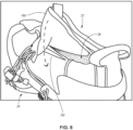
- the closure system 30 may further include a wrap-over tongue 190, such as shown in FIG. 8 , that extends from a medial side 22 of the upper 12 toward a lateral side 24 of the upper 12.
- a wrap-over tongue 190 such as shown in FIG. 8 , that extends from a medial side 22 of the upper 12 toward a lateral side 24 of the upper 12.
- the plate 42 may begin as a die-cut or injection-molded sheet. If the base resin of the plate 42 is a thermoplastic polymer, the sheet may be heated and bent around a mold that has the contours of the upper plate 60, lower plate 62, and joint 64. Once the plate 42 is formed about this tool the up-turned sole portions 140 may then be formed via localized heating and forming. In an alternative embodiment, the plate may be injection molded into its finished form. In some embodiments, the outsole 38 may be integral to the lower plate 62, such as by being insert molded or co-molded with the plate 42. In another embodiment, the outsole 38 may be adhered to the lower plate 62, for example, via a suitable adhesive.
- any directional references used herein presume that the article of footwear is positioned in an upright posture on a flat, horizonal ground plane, such that the outsole is in contact with the ground plane (i.e., as if worn by a user standing in an upright manner)
Landscapes
- Chemical & Material Sciences (AREA)
- Engineering & Computer Science (AREA)
- Materials Engineering (AREA)
- Footwear And Its Accessory, Manufacturing Method And Apparatuses (AREA)
Claims (15)
- Sohlenstruktur (14) für ein Schuhwerk (10) mit einem Fersenbereich (20), einem Mittelfußbereich (18) und einem Vorderfußbereich (16), wobei die Sohlenstruktur umfasst:eine Zwischensohle (36);eine bodenberührende Außensohlenfläche (38); undein Dämpfungssystem (40), das zwischen der Zwischensohle und der bodenberührenden Außensohlenfläche angeordnet ist, wobei das Dämpfungssystem einschließt:eine Platte (42), die eine obere Platte (60) und eine untere Platte (62) definiert, die in einer beabstandeten Beziehung bereitgestellt sind, wobei die obere Platte und die untere Platte an einem hinteren Abschnitt der Sohlenstruktur integral verbunden sind;eine fluidgefüllte Mittelfußkammer (80, 82), die zwischen der oberen Platte und der unteren Platte innerhalb des Mittelfußbereichs bereitgestellt ist;eine fluidgefüllte Vorderfußkammer (84), die zwischen der oberen Platte und der unteren Platte innerhalb des Vorderfußbereichs bereitgestellt ist.
- Schuhwerk (10) mit einem Fersenbereich (20), einem Mittelfußbereich (18) und einem Vorderfußbereich (16), wobei das Schuhwerk umfasst:ein Oberteil (12) mit einem Innenvolumen, das zur Aufnahme eines Fußes eines Trägers geeignet ist;eine Sohlenstruktur (14), die an einer Unterseite des Oberteils befestigt ist, wobei die Sohlenstruktur einschließt:eine Zwischensohle (36);eine bodenberührende Außensohlenfläche (38); undein Dämpfungssystem (40), das zwischen der Zwischensohle und der bodenberührenden Außensohlenfläche angeordnet ist, wobei das Dämpfungssystem einschließt:eine Platte (42), die eine obere Platte (60) und eine untere Platte (62) definiert, die in einer beabstandeten Beziehung bereitgestellt sind, wobei die obere Platte und die untere Platte an einem hinteren Abschnitt der Sohlenstruktur integral verbunden sind;eine fluidgefüllte Mittelfußkammer (80, 82), die zwischen der oberen Platte und der unteren Platte innerhalb des Mittelfußbereichs bereitgestellt ist; undeine fluidgefüllte Vorderfußkammer (84), die zwischen der oberen Platte und der unteren Platte innerhalb des Vorderfußbereichs bereitgestellt ist.
- Sohlenstruktur nach Anspruch 1 oder Schuhwerk nach Anspruch 2, wobei die Zwischensohle eine erste Härte aufweist, die Platte eine zweite Härte aufweist und die zweite Härte größer ist als die erste Härte.
- Sohlenstruktur nach einem der Ansprüche 1 und 3 oder Schuhwerk nach einem der Ansprüche 2-3, wobei die fluidgefüllte Mittelfußkammer eine erste fluidgefüllte Mittelfußkammer und eine zweite fluidgefüllte Mittelfußkammer enthält;die erste fluidgefüllte Mittelfußkammer in Kontakt mit der oberen Platte steht und zwischen der oberen Platte und der zweiten fluidgefüllten Mittelfußkammer bereitgestellt ist; unddie zweite fluidgefüllte Mittelfußkammer in Kontakt mit der unteren Platte steht und zwischen der unteren Platte und der ersten fluidgefüllten Mittelfußkammer bereitgestellt ist.
- Sohlenstruktur nach Anspruch 4 oder Schuhwerk nach Anspruch 4, wobei mindestens eine der ersten fluidgefüllten Mittelfußkammer oder der zweiten fluidgefüllten Mittelfußkammer eine Mehrzahl von Zugelementen enthält, die sich über einen inneren Hohlraum der Kammer erstrecken.
- Sohlenstruktur nach einem der Ansprüche 1 und 3-5 oder Schuhwerk nach einem der Ansprüche 2-5, wobei die fluidgefüllte Vorderfußkammer eine laterale fluidgefüllte Vorderfußkammer und eine mediale fluidgefüllte Vorderfußkammer enthält;die laterale fluidgefüllte Vorderfußkammer zwischen einem lateralen Rand der Sohlenstruktur und der medialen fluidgefüllten Vorderfußkammer angeordnet ist; unddie mediale fluidgefüllte Vorderfußkammer zwischen einem medialen Rand der Sohlenstruktur und der lateralen fluidgefüllten Vorderfußkammer angeordnet ist.
- Sohlenstruktur nach Anspruch 6 oder Schuhwerk nach Anspruch 6, wobei mindestens eine der lateralen fluidgefüllten Vorderfußkammer oder der medialen fluidgefüllten Vorderfußkammer eine Mehrzahl von Zugelementen enthält, die sich über einen inneren Hohlraum der Kammer erstrecken.
- Sohlenstruktur nach Anspruch 1, wobei:die Zwischensohle aus einem geschäumten Polymer gebildet ist;die Platte eine Polymerplatte ist;die fluidgefüllte Mittelfußkammer mindestens zwei vertikal gestapelte fluidgefüllte Kammern umfasst, die zwischen der oberen Platte und der unteren Platte innerhalb des Mittelfußbereichs des Dämpfungssystems bereitgestellt sind, wobei die mindestens zwei vertikal gestapelten fluidgefüllten Kammern eine erste fluidgefüllte Mittelfußkammer, die mit der oberen Platte verbunden ist, und eine zweite fluidgefüllte Mittelfußkammer, die mit der ersten fluidgefüllten Mittelfußkammer und der unteren Platte verbunden und dazwischen ist, einschließen;die fluidgefüllte Vorderfußkammer mindestens zwei lateral angeordnete fluidgefüllte Kammern umfasst, die zwischen der oberen Platte und der unteren Platte innerhalb des Vorderfußbereichs des Dämpfungssystems bereitgestellt sind, wobei die mindestens zwei lateral angeordneten fluidgefüllten Kammern einschließen:
eine laterale fluidgefüllte Vorderfußkammer und eine mediale fluidgefüllte Vorderfußkammer, wobei die laterale fluidgefüllte Vorderfußkammer zwischen einem lateralen Rand der Sohlenstruktur und der medialen fluidgefüllten Vorderfußkammer angeordnet ist und die mediale fluidgefüllte Vorderfußkammer zwischen einem medialen Rand der Sohlenstruktur und der lateralen fluidgefüllten Vorderfußkammer angeordnet ist. - Sohlenstruktur nach Anspruch 8, wobei die obere Platte einen vorwärts gerichteten/vorderen Rand enthält, der von der unteren Platte beabstandet ist.
- Sohlenstruktur nach einem der Ansprüche 8-9, wobei jede der ersten fluidgefüllten Mittelfußkammer, der zweiten fluidgefüllten Mittelfußkammer, der lateralen fluidgefüllten Vorderfußkammer und der medialen fluidgefüllten Vorderfußkammer eine Mehrzahl von Zugelementen enthält, die sich über einen inneren Hohlraum der jeweiligen Kammer erstrecken.
- Sohlenstruktur nach einem der Ansprüche 1 und 3-10, wobei das Dämpfungssystem eine offene Öffnung aufweist, die sich durch das Dämpfungssystem vom lateralen Rand zum medialen Rand erstreckt.
- Sohlenstruktur nach einem der Ansprüche 1 und 3-11, wobei die bodenberührende Außensohlenfläche an einer Außenfläche der unteren Platte bereitgestellt ist.
- Sohlenstruktur nach einem der Ansprüche 1 und 3-12, wobei das Dämpfungssystem einen Polymerstoßfänger enthält, der innerhalb des Fersenbereichs bereitgestellt und an einer Innenfläche der oberen Platte befestigt ist, und wobei der Polymerstoßfänger von der unteren Platte beabstandet ist, wenn sich das Dämpfungssystem in einem undeformierten Zustand befindet.
- Sohlenstruktur nach Anspruch 1, wobei der Vorderfußbereich der Sohlenstruktur einen Spalt umfasst, der sich von einem vorderen Ende der Sohlenstruktur aus erstreckt, und wobei der Spalt den Vorderfußbereich physisch in einen medialen Vorderfußzehenbereich und einen lateralen Vorderfußzehenbereich auftrennt.
- Schuhwerk nach Anspruch 2, weiter umfassend einen Spalt, der sich von einem vorderen Rand des Vorderfußbereichs aus erstreckt und einen Teil des Oberteils, der Zwischensohle und der unteren Platte jeweils in einen medialen Vorderfußzehenbereich und einen lateralen Vorderfußzehenbereich auftrennt.
Applications Claiming Priority (2)
| Application Number | Priority Date | Filing Date | Title |
|---|---|---|---|
| US201962822322P | 2019-03-22 | 2019-03-22 | |
| PCT/US2020/023959 WO2020198045A1 (en) | 2019-03-22 | 2020-03-20 | Article of footwear with zonal cushioning system |
Publications (2)
| Publication Number | Publication Date |
|---|---|
| EP3941297A1 EP3941297A1 (de) | 2022-01-26 |
| EP3941297B1 true EP3941297B1 (de) | 2025-03-19 |
Family
ID=70293109
Family Applications (1)
| Application Number | Title | Priority Date | Filing Date |
|---|---|---|---|
| EP20719858.1A Active EP3941297B1 (de) | 2019-03-22 | 2020-03-20 | Schuhwerk mit zonalem polstersystem |
Country Status (4)
| Country | Link |
|---|---|
| US (2) | US11311076B2 (de) |
| EP (1) | EP3941297B1 (de) |
| CN (2) | CN113423299B (de) |
| WO (1) | WO2020198045A1 (de) |
Families Citing this family (32)
| Publication number | Priority date | Publication date | Assignee | Title |
|---|---|---|---|---|
| CN113423299B (zh) * | 2019-03-22 | 2023-03-14 | 耐克创新有限合伙公司 | 具有区域性缓冲系统的鞋类物品 |
| USD915047S1 (en) * | 2019-08-30 | 2021-04-06 | Nike, Inc. | Shoe |
| USD912949S1 (en) * | 2019-08-30 | 2021-03-16 | Nike, Inc. | Shoe |
| USD918547S1 (en) | 2019-08-30 | 2021-05-11 | Nike, Inc. | Shoe |
| USD915037S1 (en) * | 2019-08-30 | 2021-04-06 | Nike, Inc. | Shoe |
| USD932150S1 (en) * | 2019-12-17 | 2021-10-05 | Nike, Inc. | Shoe |
| USD938702S1 (en) | 2019-12-17 | 2021-12-21 | Nike, Inc. | Shoe |
| USD958502S1 (en) | 2019-12-17 | 2022-07-26 | Nike, Inc. | Shoe |
| EP4157023B1 (de) * | 2020-05-31 | 2024-08-07 | Nike Innovate C.V. | Sohlenstruktur für schuhwerk |
| USD955725S1 (en) * | 2020-08-18 | 2022-06-28 | Nike, Inc. | Shoe |
| USD955726S1 (en) * | 2020-08-27 | 2022-06-28 | Nike, Inc. | Shoe |
| USD1011708S1 (en) * | 2020-09-22 | 2024-01-23 | Puma SE | Shoe |
| WO2022072832A1 (en) * | 2020-10-02 | 2022-04-07 | Nike Innovate C.V. | Article of footwear with zonal cushioning system |
| USD932158S1 (en) * | 2020-10-29 | 2021-10-05 | Nike, Inc. | Shoe |
| USD936341S1 (en) * | 2020-12-21 | 2021-11-23 | Nike, Inc. | Shoe |
| USD934541S1 (en) * | 2020-12-22 | 2021-11-02 | Nike, Inc. | Shoe |
| EP4287903B1 (de) * | 2021-02-08 | 2026-01-21 | Nike Innovate C.V. | Sohlenstruktur für schuhwerk |
| US12250988B2 (en) | 2021-02-08 | 2025-03-18 | Nike, Inc. | Sole structure for article of footwear |
| USD939197S1 (en) * | 2021-02-26 | 2021-12-28 | Nike, Inc. | Shoe |
| USD938709S1 (en) * | 2021-02-26 | 2021-12-21 | Nike, Inc. | Shoe |
| USD1029469S1 (en) | 2021-03-24 | 2024-06-04 | Nike, Inc. | Shoe |
| USD945756S1 (en) * | 2021-04-14 | 2022-03-15 | Nike, Inc. | Shoe |
| USD981095S1 (en) * | 2021-07-15 | 2023-03-21 | Hailin Chen | Sole |
| US11633007B2 (en) * | 2021-07-25 | 2023-04-25 | Deckers Outdoor Corporation | Sole including a support member |
| USD961896S1 (en) * | 2021-08-17 | 2022-08-30 | Nike, Inc. | Shoe |
| USD961894S1 (en) * | 2021-08-17 | 2022-08-30 | Nike, Inc. | Shoe |
| USD976550S1 (en) | 2021-09-30 | 2023-01-31 | Nike, Inc. | Shoe |
| USD972820S1 (en) * | 2021-09-30 | 2022-12-20 | Nike, Inc. | Shoe |
| WO2023114687A1 (en) * | 2021-12-16 | 2023-06-22 | Nike, Inc. | An article of footwear having a sole structure |
| USD1000760S1 (en) * | 2022-06-10 | 2023-10-10 | Fujian Daocheng Electronic Commerce Co., Ltd. | Shoe |
| USD990853S1 (en) * | 2022-08-23 | 2023-07-04 | Nike, Inc. | Shoe |
| EP4368052A1 (de) * | 2022-11-14 | 2024-05-15 | Puma Se | Schuhartikel mit austauschbaren hülsen |
Citations (1)
| Publication number | Priority date | Publication date | Assignee | Title |
|---|---|---|---|---|
| US20140075778A1 (en) * | 2012-09-20 | 2014-03-20 | Nike, Inc. | Sole Structures and Articles of Footwear Having Plate Moderated Fluid-Filled Bladders and/or Foam Type Impact Force Attenuation Members |
Family Cites Families (94)
| Publication number | Priority date | Publication date | Assignee | Title |
|---|---|---|---|---|
| US1870114A (en) * | 1931-08-12 | 1932-08-02 | Edwin H Heller | Shoe ventilating device |
| US2437227A (en) * | 1947-03-05 | 1948-03-02 | Hall Manville | Cushioned shoe sole |
| US2721400A (en) * | 1952-03-31 | 1955-10-25 | Israel Samuel | Cushioned shoe sole |
| US4439936A (en) * | 1982-06-03 | 1984-04-03 | Nike, Inc. | Shock attenuating outer sole |
| US5003709A (en) * | 1988-03-31 | 1991-04-02 | Rikio Co., Ltd. | Prick-preventing shoe |
| GB2221378A (en) * | 1988-08-02 | 1990-02-07 | Far East Athletics Limited | Sole with the compressible shock absorbers |
| US5138776A (en) * | 1988-12-12 | 1992-08-18 | Shalom Levin | Sports shoe |
| US5353523A (en) * | 1991-08-02 | 1994-10-11 | Nike, Inc. | Shoe with an improved midsole |
| US6453577B1 (en) * | 1996-02-09 | 2002-09-24 | Reebok International Ltd. | Support and cushioning system for an article of footwear |
| US6115943A (en) * | 1995-10-02 | 2000-09-12 | Gyr; Kaj | Footwear having an articulating heel portion |
| USD382690S (en) * | 1996-05-21 | 1997-08-26 | Aki Hirahata | Split toe sneaker |
| US5901467A (en) * | 1997-12-11 | 1999-05-11 | American Sporting Goods Corporation | Shoe construction including pneumatic shock attenuation members |
| US7107235B2 (en) * | 2000-03-10 | 2006-09-12 | Lyden Robert M | Method of conducting business including making and selling a custom article of footwear |
| US6385864B1 (en) * | 2000-03-16 | 2002-05-14 | Nike, Inc. | Footwear bladder with controlled flex tensile member |
| US6571490B2 (en) * | 2000-03-16 | 2003-06-03 | Nike, Inc. | Bladder with multi-stage regionalized cushioning |
| US6487796B1 (en) * | 2001-01-02 | 2002-12-03 | Nike, Inc. | Footwear with lateral stabilizing sole |
| JP3947658B2 (ja) * | 2001-06-28 | 2007-07-25 | 美津濃株式会社 | スポーツ用シューズのミッドソール構造 |
| US6964120B2 (en) * | 2001-11-02 | 2005-11-15 | Nike, Inc. | Footwear midsole with compressible element in lateral heel area |
| US6851204B2 (en) * | 2001-11-15 | 2005-02-08 | Nike, Inc. | Footwear sole with a stiffness adjustment mechanism |
| US6898870B1 (en) * | 2002-03-20 | 2005-05-31 | Nike, Inc. | Footwear sole having support elements with compressible apertures |
| JP5236146B2 (ja) * | 2002-06-06 | 2013-07-17 | グリンデン ロック ジー.エム.ビー.エイチ. | 表底 |
| US20090133288A1 (en) * | 2003-04-07 | 2009-05-28 | Gallegos Alvaro Z | Footwear with two-plate system |
| JP2005013718A (ja) * | 2003-06-05 | 2005-01-20 | Mizuno Corp | シューズのソール構造体 |
| US6925732B1 (en) * | 2003-06-19 | 2005-08-09 | Nike, Inc. | Footwear with separated upper and sole structure |
| US7100308B2 (en) * | 2003-11-21 | 2006-09-05 | Nike, Inc. | Footwear with a heel plate assembly |
| US7082703B2 (en) * | 2004-01-30 | 2006-08-01 | Nike, Inc. | Article of footwear for sand sports |
| US7200955B2 (en) * | 2004-06-04 | 2007-04-10 | Nike, Inc. | Article of footwear incorporating a sole structure with compressible inserts |
| US7334351B2 (en) * | 2004-06-07 | 2008-02-26 | Energy Management Athletics, Llc | Shoe apparatus with improved efficiency |
| US7152343B2 (en) * | 2004-06-25 | 2006-12-26 | Cronus, Inc. | Footwear system |
| US20060010715A1 (en) * | 2004-07-19 | 2006-01-19 | Yu-Lin Tseng | Footwear with resilient heel |
| WO2006032014A2 (en) * | 2004-09-14 | 2006-03-23 | Tripod, L.L.C. | Sole unit for footwear and footwear incorporating same |
| JP3689770B1 (ja) * | 2004-09-17 | 2005-08-31 | 株式会社アーバンナワチ | 靴構造の履物 |
| US7458172B2 (en) * | 2004-09-27 | 2008-12-02 | Nike, Inc. | Impact attenuating devices and products containing such devices |
| JP4452721B2 (ja) * | 2004-09-30 | 2010-04-21 | 株式会社アシックス | 靴底の緩衝装置 |
| US8205356B2 (en) * | 2004-11-22 | 2012-06-26 | Frampton E. Ellis | Devices with internal flexibility sipes, including siped chambers for footwear |
| US7814683B2 (en) * | 2004-12-15 | 2010-10-19 | Ryn Korea Co., Ltd. | Health footwear having improved heel |
| CN100584233C (zh) * | 2004-12-27 | 2010-01-27 | 美津浓株式会社 | 鞋的鞋底结构 |
| US7493708B2 (en) * | 2005-02-18 | 2009-02-24 | Nike, Inc. | Article of footwear with plate dividing a support column |
| US7546695B2 (en) * | 2005-02-25 | 2009-06-16 | Nike, Inc. | Foot-support structures with additional shear support and products containing such support structures |
| WO2006129392A1 (ja) * | 2005-05-30 | 2006-12-07 | Mizuno Corporation | シューズのソール構造体 |
| US7360324B2 (en) * | 2005-08-15 | 2008-04-22 | Nike, Inc. | Article of footwear with spherical support elements |
| US20070033830A1 (en) * | 2005-08-15 | 2007-02-15 | Kuei-Lin Chang | Elastic shoe |
| US7437838B2 (en) * | 2005-09-23 | 2008-10-21 | Srl, Inc. | Article of footwear |
| US20070101617A1 (en) * | 2005-11-10 | 2007-05-10 | Fila Luxembourg S.A.R.L. | Footwear sole assembly having spring mechanism |
| KR101366673B1 (ko) * | 2006-03-03 | 2014-02-24 | 더블유.엘.고어 앤드 어소시에이츠 게엠베하 | 복합체 슈즈 밑창, 이로 구성된 신발, 및 이의 제조 방법 |
| US7673397B2 (en) * | 2006-05-04 | 2010-03-09 | Nike, Inc. | Article of footwear with support assembly having plate and indentations formed therein |
| US7707743B2 (en) * | 2006-05-19 | 2010-05-04 | Nike, Inc. | Article of footwear with multi-layered support assembly |
| US7757410B2 (en) * | 2006-06-05 | 2010-07-20 | Nike, Inc. | Impact-attenuation members with lateral and shear force stability and products containing such members |
| US7685742B2 (en) * | 2006-07-21 | 2010-03-30 | Nike, Inc. | Impact-attenuation systems for articles of footwear and other foot-receiving devices |
| JP4153002B2 (ja) * | 2006-08-30 | 2008-09-17 | 美津濃株式会社 | シューズのソール組立体の中足部構造 |
| US7748142B2 (en) * | 2006-09-26 | 2010-07-06 | Nike, Inc. | Article of footwear for long jumping |
| US7997011B2 (en) * | 2006-10-03 | 2011-08-16 | Nike, Inc. | Footwear with support assembly having spring arms |
| US20080115386A1 (en) * | 2006-11-17 | 2008-05-22 | Geuss Donald R | Split-toed shoe |
| US7793428B2 (en) * | 2007-03-07 | 2010-09-14 | Nike, Inc. | Footwear with removable midsole having projections |
| US7971374B2 (en) * | 2007-04-24 | 2011-07-05 | Hernandez Peter J | Apparatus for use in footwear and the like |
| US8978273B2 (en) * | 2007-10-19 | 2015-03-17 | Nike, Inc. | Article of footwear with a sole structure having fluid-filled support elements |
| US20090126224A1 (en) * | 2007-11-19 | 2009-05-21 | Greene Pamela S | Differential-stiffness impact-attenuation members and products including them |
| US8151485B2 (en) * | 2008-01-11 | 2012-04-10 | Nike, Inc. | Article of footwear with forefoot plates |
| JP4388580B2 (ja) * | 2008-03-28 | 2009-12-24 | 美津濃株式会社 | スポーツ用シューズのインソール構造体 |
| JP4874349B2 (ja) * | 2008-03-31 | 2012-02-15 | 美津濃株式会社 | シューズのソール構造体 |
| US8510970B2 (en) * | 2010-03-30 | 2013-08-20 | Howard Baum | Shoe sole with energy restoring device |
| US8943709B2 (en) * | 2008-11-06 | 2015-02-03 | Nike, Inc. | Article of footwear with support columns having fluid-filled bladders |
| JP2010162318A (ja) * | 2009-01-19 | 2010-07-29 | Tatsuya Nakatsuka | ランニングシューズ |
| US9750307B2 (en) * | 2013-02-21 | 2017-09-05 | Nike, Inc. | Article of footwear having a sole structure including a fluid-filled chamber and an outsole, the sole structure, and methods for manufacturing |
| US9894959B2 (en) * | 2009-12-03 | 2018-02-20 | Nike, Inc. | Tethered fluid-filled chamber with multiple tether configurations |
| US8479412B2 (en) * | 2009-12-03 | 2013-07-09 | Nike, Inc. | Tethered fluid-filled chambers |
| DE102009054617B4 (de) * | 2009-12-14 | 2018-05-30 | Adidas Ag | Schuh |
| US8991072B2 (en) * | 2010-02-22 | 2015-03-31 | Nike, Inc. | Fluid-filled chamber incorporating a flexible plate |
| JP5392954B2 (ja) * | 2010-04-02 | 2014-01-22 | 美津濃株式会社 | シューズのソール構造体 |
| USD682514S1 (en) * | 2011-07-22 | 2013-05-21 | Conscious Corporation | Divided-toe shoe |
| US8991075B2 (en) * | 2011-11-10 | 2015-03-31 | S9, Llc | Three toed footwear |
| US9750300B2 (en) | 2011-12-23 | 2017-09-05 | Nike, Inc. | Article of footwear having an elevated plate sole structure |
| US9491984B2 (en) * | 2011-12-23 | 2016-11-15 | Nike, Inc. | Article of footwear having an elevated plate sole structure |
| US10034517B2 (en) * | 2011-12-29 | 2018-07-31 | Reebok International Limited | Sole and article of footwear having a pod assembly |
| US9282784B2 (en) * | 2012-09-06 | 2016-03-15 | Nike, Inc. | Sole structures and articles of footwear having a lightweight midsole with segmented protective elements |
| US20140068966A1 (en) * | 2012-09-11 | 2014-03-13 | Timothy Roy Chaffin | Suspension system for shoes comprised of carbon fiber springs and other components. |
| US10849387B2 (en) * | 2012-09-20 | 2020-12-01 | Nike, Inc. | Sole structures and articles of footwear having plate moderated fluid-filled bladders and/or foam type impact force attenuation members |
| US9456658B2 (en) * | 2012-09-20 | 2016-10-04 | Nike, Inc. | Sole structures and articles of footwear having plate moderated fluid-filled bladders and/or foam type impact force attenuation members |
| US9320313B2 (en) * | 2013-02-20 | 2016-04-26 | Nike, Inc. | Split-sole footwear |
| US9241535B2 (en) * | 2013-03-14 | 2016-01-26 | Nike, Inc. | Sole structures and articles incorporating same |
| US20140290098A1 (en) * | 2013-03-26 | 2014-10-02 | Wolverine World Wide, Inc. | Sole assembly for article of footwear |
| US9629414B2 (en) * | 2013-07-11 | 2017-04-25 | Nike, Inc. | Sole structure for an article of footwear |
| US9687042B2 (en) * | 2013-08-07 | 2017-06-27 | Nike, Inc. | Article of footwear with a midsole structure |
| US9480303B2 (en) * | 2013-08-09 | 2016-11-01 | Nike, Inc. | Sole structure for an article of footwear |
| WO2016032894A1 (en) * | 2014-08-29 | 2016-03-03 | Nike Innovate C.V. | Sole assembly for an article of footwear with bowed spring plate |
| WO2016109817A1 (en) * | 2014-12-31 | 2016-07-07 | Chinook Asia Llc | Footwear having a flex-spring sole |
| ITUB20150705A1 (it) * | 2015-05-18 | 2016-11-18 | Jv Int S R L | Suola per calzature e calzatura comprendente una tale suola |
| JP6310427B2 (ja) * | 2015-08-07 | 2018-04-11 | 美津濃株式会社 | シューズのソール構造 |
| EP3370560B1 (de) * | 2015-11-03 | 2023-03-22 | Nike Innovate C.V. | Fussbekleidungsartikel mit beabstandeten polsterteilen, die an einer bodenseitigen oberfläche eines schuhoberteils angebracht sind, und verfahren zur herstellung eines schuhwerks |
| CN109068798B (zh) * | 2016-04-01 | 2021-08-17 | 耐克创新有限合伙公司 | 具有自适应配合的鞋类物品 |
| CN109068787B (zh) * | 2016-05-13 | 2021-11-26 | 耐克创新有限合伙公司 | 用于举重的鞋类物品 |
| EP3345499B1 (de) * | 2017-01-09 | 2020-03-11 | ATMOS airwalk ag | Schuh mit einer luftpumpeinrichtung mit einem einen balg umgreifenden federelement |
| KR102207241B1 (ko) * | 2017-02-01 | 2021-01-22 | 나이키 이노베이트 씨.브이. | 밑창 구조체를 위한 적층형 완충 장치 |
| CN113423299B (zh) * | 2019-03-22 | 2023-03-14 | 耐克创新有限合伙公司 | 具有区域性缓冲系统的鞋类物品 |
-
2020
- 2020-03-20 CN CN202080013469.2A patent/CN113423299B/zh active Active
- 2020-03-20 CN CN202310196043.0A patent/CN115989913A/zh active Pending
- 2020-03-20 US US16/825,746 patent/US11311076B2/en active Active
- 2020-03-20 EP EP20719858.1A patent/EP3941297B1/de active Active
- 2020-03-20 WO PCT/US2020/023959 patent/WO2020198045A1/en not_active Ceased
-
2022
- 2022-04-06 US US17/714,243 patent/US11751628B2/en active Active
Patent Citations (1)
| Publication number | Priority date | Publication date | Assignee | Title |
|---|---|---|---|---|
| US20140075778A1 (en) * | 2012-09-20 | 2014-03-20 | Nike, Inc. | Sole Structures and Articles of Footwear Having Plate Moderated Fluid-Filled Bladders and/or Foam Type Impact Force Attenuation Members |
Also Published As
| Publication number | Publication date |
|---|---|
| EP3941297A1 (de) | 2022-01-26 |
| CN113423299B (zh) | 2023-03-14 |
| US11311076B2 (en) | 2022-04-26 |
| WO2020198045A1 (en) | 2020-10-01 |
| CN113423299A (zh) | 2021-09-21 |
| US20200297071A1 (en) | 2020-09-24 |
| US11751628B2 (en) | 2023-09-12 |
| US20220279896A1 (en) | 2022-09-08 |
| CN115989913A (zh) | 2023-04-21 |
Similar Documents
| Publication | Publication Date | Title |
|---|---|---|
| US11751628B2 (en) | Article of footwear with zonal cushioning system | |
| US12453392B2 (en) | Sole structure for article of footwear | |
| US12501969B2 (en) | Stacked cushioning arrangement for sole structure | |
| US12471668B2 (en) | Cushioning member for article of footwear | |
| US12239183B2 (en) | Article of footwear | |
| US11779078B2 (en) | Article of footwear with zonal cushioning system | |
| US10244821B2 (en) | Sole structure for an artricle of footwear | |
| EP2755516B1 (de) | Fussbekleidungsartikel | |
| EP2833751B1 (de) | Sohlenaufbau für schuhwerk | |
| US8549774B2 (en) | Flexible shank for an article of footwear | |
| US12426668B2 (en) | Article of footwear | |
| US20150040432A1 (en) | Article of footwear with a midsole structure | |
| US20220125160A1 (en) | Sole structure having an outsole with integrated traction elements | |
| EP2369951A2 (de) | Fussbekleidungsartikel mit einem stossdämpfer und einem von der sohle in einem mittleren fussbereich entkoppelten obermaterial | |
| US11517073B2 (en) | Article of footwear with midfoot flexibility | |
| EP4221534B1 (de) | Schuhartikel mit zonalem polstersystem |
Legal Events
| Date | Code | Title | Description |
|---|---|---|---|
| STAA | Information on the status of an ep patent application or granted ep patent |
Free format text: STATUS: UNKNOWN |
|
| STAA | Information on the status of an ep patent application or granted ep patent |
Free format text: STATUS: THE INTERNATIONAL PUBLICATION HAS BEEN MADE |
|
| PUAI | Public reference made under article 153(3) epc to a published international application that has entered the european phase |
Free format text: ORIGINAL CODE: 0009012 |
|
| STAA | Information on the status of an ep patent application or granted ep patent |
Free format text: STATUS: REQUEST FOR EXAMINATION WAS MADE |
|
| 17P | Request for examination filed |
Effective date: 20210701 |
|
| AK | Designated contracting states |
Kind code of ref document: A1 Designated state(s): AL AT BE BG CH CY CZ DE DK EE ES FI FR GB GR HR HU IE IS IT LI LT LU LV MC MK MT NL NO PL PT RO RS SE SI SK SM TR |
|
| DAV | Request for validation of the european patent (deleted) | ||
| DAX | Request for extension of the european patent (deleted) | ||
| P01 | Opt-out of the competence of the unified patent court (upc) registered |
Effective date: 20230515 |
|
| GRAP | Despatch of communication of intention to grant a patent |
Free format text: ORIGINAL CODE: EPIDOSNIGR1 |
|
| STAA | Information on the status of an ep patent application or granted ep patent |
Free format text: STATUS: GRANT OF PATENT IS INTENDED |
|
| INTG | Intention to grant announced |
Effective date: 20241010 |
|
| GRAS | Grant fee paid |
Free format text: ORIGINAL CODE: EPIDOSNIGR3 |
|
| GRAA | (expected) grant |
Free format text: ORIGINAL CODE: 0009210 |
|
| STAA | Information on the status of an ep patent application or granted ep patent |
Free format text: STATUS: THE PATENT HAS BEEN GRANTED |
|
| AK | Designated contracting states |
Kind code of ref document: B1 Designated state(s): AL AT BE BG CH CY CZ DE DK EE ES FI FR GB GR HR HU IE IS IT LI LT LU LV MC MK MT NL NO PL PT RO RS SE SI SK SM TR |
|
| REG | Reference to a national code |
Ref country code: GB Ref legal event code: FG4D |
|
| REG | Reference to a national code |
Ref country code: CH Ref legal event code: EP |
|
| REG | Reference to a national code |
Ref country code: DE Ref legal event code: R096 Ref document number: 602020047903 Country of ref document: DE |
|
| REG | Reference to a national code |
Ref country code: IE Ref legal event code: FG4D |
|
| PG25 | Lapsed in a contracting state [announced via postgrant information from national office to epo] |
Ref country code: RS Free format text: LAPSE BECAUSE OF FAILURE TO SUBMIT A TRANSLATION OF THE DESCRIPTION OR TO PAY THE FEE WITHIN THE PRESCRIBED TIME-LIMIT Effective date: 20250619 |
|
| PG25 | Lapsed in a contracting state [announced via postgrant information from national office to epo] |
Ref country code: FI Free format text: LAPSE BECAUSE OF FAILURE TO SUBMIT A TRANSLATION OF THE DESCRIPTION OR TO PAY THE FEE WITHIN THE PRESCRIBED TIME-LIMIT Effective date: 20250319 |
|
| REG | Reference to a national code |
Ref country code: LT Ref legal event code: MG9D |
|
| PG25 | Lapsed in a contracting state [announced via postgrant information from national office to epo] |
Ref country code: NO Free format text: LAPSE BECAUSE OF FAILURE TO SUBMIT A TRANSLATION OF THE DESCRIPTION OR TO PAY THE FEE WITHIN THE PRESCRIBED TIME-LIMIT Effective date: 20250619 |
|
| PG25 | Lapsed in a contracting state [announced via postgrant information from national office to epo] |
Ref country code: HR Free format text: LAPSE BECAUSE OF FAILURE TO SUBMIT A TRANSLATION OF THE DESCRIPTION OR TO PAY THE FEE WITHIN THE PRESCRIBED TIME-LIMIT Effective date: 20250319 |
|
| PG25 | Lapsed in a contracting state [announced via postgrant information from national office to epo] |
Ref country code: LV Free format text: LAPSE BECAUSE OF FAILURE TO SUBMIT A TRANSLATION OF THE DESCRIPTION OR TO PAY THE FEE WITHIN THE PRESCRIBED TIME-LIMIT Effective date: 20250319 |
|
| PG25 | Lapsed in a contracting state [announced via postgrant information from national office to epo] |
Ref country code: GR Free format text: LAPSE BECAUSE OF FAILURE TO SUBMIT A TRANSLATION OF THE DESCRIPTION OR TO PAY THE FEE WITHIN THE PRESCRIBED TIME-LIMIT Effective date: 20250620 Ref country code: BG Free format text: LAPSE BECAUSE OF FAILURE TO SUBMIT A TRANSLATION OF THE DESCRIPTION OR TO PAY THE FEE WITHIN THE PRESCRIBED TIME-LIMIT Effective date: 20250319 |
|
| REG | Reference to a national code |
Ref country code: NL Ref legal event code: MP Effective date: 20250319 |
|
| REG | Reference to a national code |
Ref country code: AT Ref legal event code: MK05 Ref document number: 1776179 Country of ref document: AT Kind code of ref document: T Effective date: 20250319 |
|
| PG25 | Lapsed in a contracting state [announced via postgrant information from national office to epo] |
Ref country code: NL Free format text: LAPSE BECAUSE OF FAILURE TO SUBMIT A TRANSLATION OF THE DESCRIPTION OR TO PAY THE FEE WITHIN THE PRESCRIBED TIME-LIMIT Effective date: 20250319 |
|
| PG25 | Lapsed in a contracting state [announced via postgrant information from national office to epo] |
Ref country code: SE Free format text: LAPSE BECAUSE OF FAILURE TO SUBMIT A TRANSLATION OF THE DESCRIPTION OR TO PAY THE FEE WITHIN THE PRESCRIBED TIME-LIMIT Effective date: 20250319 |
|
| PG25 | Lapsed in a contracting state [announced via postgrant information from national office to epo] |
Ref country code: SM Free format text: LAPSE BECAUSE OF FAILURE TO SUBMIT A TRANSLATION OF THE DESCRIPTION OR TO PAY THE FEE WITHIN THE PRESCRIBED TIME-LIMIT Effective date: 20250319 |
|
| PG25 | Lapsed in a contracting state [announced via postgrant information from national office to epo] |
Ref country code: PT Free format text: LAPSE BECAUSE OF FAILURE TO SUBMIT A TRANSLATION OF THE DESCRIPTION OR TO PAY THE FEE WITHIN THE PRESCRIBED TIME-LIMIT Effective date: 20250721 Ref country code: ES Free format text: LAPSE BECAUSE OF FAILURE TO SUBMIT A TRANSLATION OF THE DESCRIPTION OR TO PAY THE FEE WITHIN THE PRESCRIBED TIME-LIMIT Effective date: 20250319 |
|
| PG25 | Lapsed in a contracting state [announced via postgrant information from national office to epo] |
Ref country code: PL Free format text: LAPSE BECAUSE OF FAILURE TO SUBMIT A TRANSLATION OF THE DESCRIPTION OR TO PAY THE FEE WITHIN THE PRESCRIBED TIME-LIMIT Effective date: 20250319 Ref country code: IT Free format text: LAPSE BECAUSE OF FAILURE TO SUBMIT A TRANSLATION OF THE DESCRIPTION OR TO PAY THE FEE WITHIN THE PRESCRIBED TIME-LIMIT Effective date: 20250319 |
|
| PG25 | Lapsed in a contracting state [announced via postgrant information from national office to epo] |
Ref country code: AT Free format text: LAPSE BECAUSE OF FAILURE TO SUBMIT A TRANSLATION OF THE DESCRIPTION OR TO PAY THE FEE WITHIN THE PRESCRIBED TIME-LIMIT Effective date: 20250319 |
|
| PG25 | Lapsed in a contracting state [announced via postgrant information from national office to epo] |
Ref country code: CZ Free format text: LAPSE BECAUSE OF FAILURE TO SUBMIT A TRANSLATION OF THE DESCRIPTION OR TO PAY THE FEE WITHIN THE PRESCRIBED TIME-LIMIT Effective date: 20250319 Ref country code: EE Free format text: LAPSE BECAUSE OF FAILURE TO SUBMIT A TRANSLATION OF THE DESCRIPTION OR TO PAY THE FEE WITHIN THE PRESCRIBED TIME-LIMIT Effective date: 20250319 |
|
| PG25 | Lapsed in a contracting state [announced via postgrant information from national office to epo] |
Ref country code: RO Free format text: LAPSE BECAUSE OF FAILURE TO SUBMIT A TRANSLATION OF THE DESCRIPTION OR TO PAY THE FEE WITHIN THE PRESCRIBED TIME-LIMIT Effective date: 20250319 |
|
| REG | Reference to a national code |
Ref country code: CH Ref legal event code: H13 Free format text: ST27 STATUS EVENT CODE: U-0-0-H10-H13 (AS PROVIDED BY THE NATIONAL OFFICE) Effective date: 20251024 |
|
| PG25 | Lapsed in a contracting state [announced via postgrant information from national office to epo] |
Ref country code: SK Free format text: LAPSE BECAUSE OF FAILURE TO SUBMIT A TRANSLATION OF THE DESCRIPTION OR TO PAY THE FEE WITHIN THE PRESCRIBED TIME-LIMIT Effective date: 20250319 |
|
| PG25 | Lapsed in a contracting state [announced via postgrant information from national office to epo] |
Ref country code: IS Free format text: LAPSE BECAUSE OF FAILURE TO SUBMIT A TRANSLATION OF THE DESCRIPTION OR TO PAY THE FEE WITHIN THE PRESCRIBED TIME-LIMIT Effective date: 20250719 |
|
| PG25 | Lapsed in a contracting state [announced via postgrant information from national office to epo] |
Ref country code: LU Free format text: LAPSE BECAUSE OF NON-PAYMENT OF DUE FEES Effective date: 20250320 |
|
| REG | Reference to a national code |
Ref country code: BE Ref legal event code: MM Effective date: 20250331 |
|
| PG25 | Lapsed in a contracting state [announced via postgrant information from national office to epo] |
Ref country code: MC Free format text: LAPSE BECAUSE OF FAILURE TO SUBMIT A TRANSLATION OF THE DESCRIPTION OR TO PAY THE FEE WITHIN THE PRESCRIBED TIME-LIMIT Effective date: 20250319 |
|
| REG | Reference to a national code |
Ref country code: DE Ref legal event code: R097 Ref document number: 602020047903 Country of ref document: DE |
|
| PG25 | Lapsed in a contracting state [announced via postgrant information from national office to epo] |
Ref country code: DK Free format text: LAPSE BECAUSE OF FAILURE TO SUBMIT A TRANSLATION OF THE DESCRIPTION OR TO PAY THE FEE WITHIN THE PRESCRIBED TIME-LIMIT Effective date: 20250319 |
|
| PGFP | Annual fee paid to national office [announced via postgrant information from national office to epo] |
Ref country code: FR Payment date: 20251231 Year of fee payment: 7 |
|
| PG25 | Lapsed in a contracting state [announced via postgrant information from national office to epo] |
Ref country code: BE Free format text: LAPSE BECAUSE OF NON-PAYMENT OF DUE FEES Effective date: 20250331 |
|
| PG25 | Lapsed in a contracting state [announced via postgrant information from national office to epo] |
Ref country code: CH Free format text: LAPSE BECAUSE OF NON-PAYMENT OF DUE FEES Effective date: 20250331 |
|
| PG25 | Lapsed in a contracting state [announced via postgrant information from national office to epo] |
Ref country code: IE Free format text: LAPSE BECAUSE OF NON-PAYMENT OF DUE FEES Effective date: 20250320 |
|
| PLBE | No opposition filed within time limit |
Free format text: ORIGINAL CODE: 0009261 |
|
| STAA | Information on the status of an ep patent application or granted ep patent |
Free format text: STATUS: NO OPPOSITION FILED WITHIN TIME LIMIT |
|
| REG | Reference to a national code |
Ref country code: CH Ref legal event code: L10 Free format text: ST27 STATUS EVENT CODE: U-0-0-L10-L00 (AS PROVIDED BY THE NATIONAL OFFICE) Effective date: 20260128 |
|
| 26N | No opposition filed |
Effective date: 20251222 |
|
| PGFP | Annual fee paid to national office [announced via postgrant information from national office to epo] |
Ref country code: GB Payment date: 20260106 Year of fee payment: 7 |
|
| PGFP | Annual fee paid to national office [announced via postgrant information from national office to epo] |
Ref country code: DE Payment date: 20260102 Year of fee payment: 7 |