US11633007B2 - Sole including a support member - Google Patents
Sole including a support member Download PDFInfo
- Publication number
- US11633007B2 US11633007B2 US17/384,783 US202117384783A US11633007B2 US 11633007 B2 US11633007 B2 US 11633007B2 US 202117384783 A US202117384783 A US 202117384783A US 11633007 B2 US11633007 B2 US 11633007B2
- Authority
- US
- United States
- Prior art keywords
- sole
- support member
- support
- hole
- footwear
- Prior art date
- Legal status (The legal status is an assumption and is not a legal conclusion. Google has not performed a legal analysis and makes no representation as to the accuracy of the status listed.)
- Active
Links
Images


Classifications
-
- A—HUMAN NECESSITIES
- A43—FOOTWEAR
- A43B—CHARACTERISTIC FEATURES OF FOOTWEAR; PARTS OF FOOTWEAR
- A43B13/00—Soles; Sole-and-heel integral units
- A43B13/14—Soles; Sole-and-heel integral units characterised by the constructive form
-
- A—HUMAN NECESSITIES
- A43—FOOTWEAR
- A43B—CHARACTERISTIC FEATURES OF FOOTWEAR; PARTS OF FOOTWEAR
- A43B13/00—Soles; Sole-and-heel integral units
- A43B13/02—Soles; Sole-and-heel integral units characterised by the material
- A43B13/12—Soles with several layers of different materials
- A43B13/125—Soles with several layers of different materials characterised by the midsole or middle layer
-
- A—HUMAN NECESSITIES
- A43—FOOTWEAR
- A43B—CHARACTERISTIC FEATURES OF FOOTWEAR; PARTS OF FOOTWEAR
- A43B13/00—Soles; Sole-and-heel integral units
- A43B13/14—Soles; Sole-and-heel integral units characterised by the constructive form
- A43B13/18—Resilient soles
- A43B13/181—Resiliency achieved by the structure of the sole
- A43B13/183—Leaf springs
-
- A—HUMAN NECESSITIES
- A43—FOOTWEAR
- A43B—CHARACTERISTIC FEATURES OF FOOTWEAR; PARTS OF FOOTWEAR
- A43B13/00—Soles; Sole-and-heel integral units
- A43B13/14—Soles; Sole-and-heel integral units characterised by the constructive form
- A43B13/18—Resilient soles
- A43B13/181—Resiliency achieved by the structure of the sole
- A43B13/185—Elasticated plates sandwiched between two interlocking components, e.g. thrustors
-
- A—HUMAN NECESSITIES
- A43—FOOTWEAR
- A43B—CHARACTERISTIC FEATURES OF FOOTWEAR; PARTS OF FOOTWEAR
- A43B13/00—Soles; Sole-and-heel integral units
- A43B13/14—Soles; Sole-and-heel integral units characterised by the constructive form
- A43B13/18—Resilient soles
- A43B13/181—Resiliency achieved by the structure of the sole
- A43B13/186—Differential cushioning region, e.g. cushioning located under the ball of the foot
-
- A—HUMAN NECESSITIES
- A43—FOOTWEAR
- A43B—CHARACTERISTIC FEATURES OF FOOTWEAR; PARTS OF FOOTWEAR
- A43B3/00—Footwear characterised by the shape or the use
- A43B3/0036—Footwear characterised by the shape or the use characterised by a special shape or design
- A43B3/0042—Footwear characterised by the shape or the use characterised by a special shape or design with circular or circle shaped parts
Definitions
- the present application relates generally to footwear, and more particularly, to a sole including at least one support member within the sole that supports a user's feet while providing resilient energy to the user's legs and feet to optimize energy efficiency and propel the user during use such as during walking, jogging and running.
- Running involves the transfer of energy between a person's legs and feet and an underlying surface, such as the ground, contributing to propelling a person forward along a trail, a sidewalk, a street or other path.
- the power a person is able to produce and the speed at which a person is able to move in a forward direction depends on a number of factors. For example, the ability to properly apply forces on a surface affects the energy produced and the rate of speed that the person is able to move.
- the propulsion generated by a person's legs and feet is important while walking, jogging or running.
- some shoes include midsoles and outsoles that are made of materials having different characteristics such as different hardness values, density and elasticity, which provide more support in some areas and less support in other areas of a person's foot leading to different shock absorption and propulsion behaviors.
- harder materials could support to foot structures during the stance, helping a proper force application and energy transfer.
- a plate is inserted or embedded in the sole of a shoe to enhance the rigidity of the sole similar to harder materials. The plate is a supportive element as well as contributing to the performance attributes of a shoe while still allowing the other materials of the sole to provide cushioning in areas of the foot, such as the heel, to provide comfort.
- the present article of footwear includes a sole having a through-hole and at least one support member positioned in the through-hole to enhance the stability and support to a user's foot during use of the article of footwear.
- an article of footwear in an embodiment, includes an upper and a sole attached to the upper, where the sole has a medial side and a lateral side, and a through-hole extending between the medial side and the lateral side.
- a support member is positioned in the through-hole of the sole, where the support member includes an upper support and a lower support and where the upper support is spaced from the lower support.
- a sole for an article of footwear in another embodiment, includes a midsole having a medial side and a lateral side, and a first through-hole and a second through-hole, where the first through-hole and the second through-hole each extend between the medial side and the lateral side.
- a first support member is positioned in the first through-hole and a second support member is positioned in the second through-hole, where the first and second support members each include an upper support and a lower support, and the upper support is spaced from the lower support.
- FIG. 1 is a perspective view of an article of footwear including the present sole
- FIG. 2 A is a top view of the embodiment of the article of footwear of FIG. 1 with the support member removed from the sole;
- FIG. 2 B is a top view of another embodiment of the article of footwear of FIG. 1 with a closed through-hole and with the support member removed from the sole;
- FIG. 3 is an elevational view of the support member in the sole shown in FIG. 1 ;
- FIG. 4 is a top view of the support member shown in FIG. 3 , wherein the bottom view is a mirror image thereof;
- FIG. 5 is a rear view of the support member shown in FIG. 3 ;
- FIG. 6 is a front view of the support member shown in FIG. 3 ;
- FIG. 7 is a perspective view of an article of footwear including another embodiment of the present sole.
- FIG. 8 is a top view of the article of footwear of FIG. 7 with the support members removed from the sole;
- FIG. 9 is an elevational view of the rear support member shown in FIG. 7 ;
- FIG. 10 is a top view of the rear support member of FIG. 9 , wherein the bottom view is a mirror image thereof;
- FIG. 11 is a front view of the rear support member of FIG. 9 , wherein the rear view is a mirror image thereof;
- FIG. 12 is an elevational view of an article of footwear including another embodiment of the present sole
- FIG. 13 is an elevational view of an embodiment of the support member within the sole shown in FIG. 12 ;
- FIG. 14 is an elevational view of another embodiment of the support member within the sole shown in FIG. 12 ;
- FIG. 15 is an elevational view of an article of footwear including a further embodiment of the present sole
- FIG. 16 is an elevational view of an article of footwear including another embodiment of the present sole
- FIG. 17 is an elevational view of an article of footwear including a further embodiment of the present sole
- FIG. 18 is a cross-section view taken generally along the line 18 - 18 in FIG. 17 in the direction generally indicated;
- FIG. 19 A is a side view of the support member shown in FIG. 17 ;
- FIG. 19 B is a top view of the support member of FIG. 19 A ;
- FIG. 19 C is a front view of the support member of FIG. 19 A ;
- FIG. 19 D is a rear view of the support member of FIG. 19 A ;
- FIG. 20 is an elevational view of another embodiment of the sole in which the sole includes two support members;
- FIG. 21 is a cross-section view taken generally along the line 21 - 21 in FIG. 20 in the direction generally indicated;
- FIG. 22 A is a side view of the first support member shown in FIG. 20 ;
- FIG. 22 B is a top view of the support member of FIG. 22 A , where the bottom view is a mirror image thereof;
- FIG. 22 C is a front view of the support member of FIG. 22 A , where the rear view is a mirror image thereof;
- FIG. 23 A is a side view of the second support member shown in FIG. 20 ;
- FIG. 23 B is a top view of the support member of FIG. 23 A , where the bottom view is a mirror image thereof;
- FIG. 23 C is a front view of the support member of FIG. 23 A , where the rear view is a mirror image thereof;
- FIG. 24 is an elevational view of another embodiment of the support member
- FIG. 25 is an elevational view of a further embodiment of the support member
- FIG. 26 is an elevational view of an embodiment that includes a plurality of support members
- FIG. 27 is an elevational view of another embodiment of the sole in which the sole includes support members and a support plate;
- FIG. 28 A is a top view of the support plate shown in FIG. 27 ;
- FIG. 28 B is a left side view of the support plate of FIG. 28 A ;
- FIG. 28 C is a right side view of the support plate of FIG. 28 A ;
- FIG. 28 D is another embodiment of the support plate in which the support plate includes a convex portion
- FIG. 29 is an elevational view of a further embodiment of the sole in which the sole includes a support member
- FIG. 30 is a perspective view of the support member of FIG. 29 ;
- FIG. 31 is a top view of the support member of FIG. 30 ;
- FIG. 32 is a bottom view of the support member of FIG. 30 ;
- FIG. 33 is a right side view of the support member of FIG. 30 , where the left side view is a mirror image thereof;
- FIG. 34 is a left side view of the sole of FIG. 29 ;
- FIG. 35 is a cross-section view taken generally along the line 35 - 35 in FIG. 36 in the direction generally indicated;
- FIG. 36 is a top view of the sole of FIG. 29 ;
- FIG. 37 is a cross-section view taken generally along the line 37 - 37 in FIG. 35 in the direction generally indicated;
- FIG. 38 is a cross-section view taken generally along the line 38 - 38 in FIG. 35 in the direction generally indicated;
- FIG. 39 is a cross-section view taken generally along the line 39 - 39 in FIG. 35 in the direction generally indicated;
- FIG. 40 is a cross-section view taken generally along the line 40 - 40 in FIG. 35 in the direction generally indicated;
- FIG. 41 is a cross-section view taken generally along the line 41 - 41 in FIG. 35 in the direction generally indicated;
- FIG. 42 is a cross-section view taken generally along the line 42 - 42 in FIG. 35 in the direction generally indicated;
- FIG. 43 is another embodiment of the support member of FIG. 29 ;
- FIG. 44 is a further embodiment of the support member of FIG. 29 ;
- FIG. 45 is another embodiment of the support member of FIG. 29 ;
- FIG. 46 is a further embodiment of the support member of FIG. 29 ;
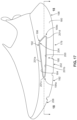
- FIG. 47 is another embodiment of the support member of FIG. 29 .
- the present sole is attached to an upper to form an article of footwear to stabilize and cushion a user's foot during walking, jogging and running, while providing enhanced stability and spring energy for efficient propulsion. More specifically, the present sole includes a midsole and an outsole where at least one support member is located on or in the midsole or outsole to provide enhanced support in the user's feet and enable the user's feet to press against the support member and propel the user in a desired direction.
- an article of footwear 20 includes an embodiment of the present sole, generally indicated as 22 , where the sole 22 includes a midsole 24 attached to an upper 26 , and an outsole 28 .
- the midsole 24 may be an integral, molded component made of a material having a designated hardness value or made with different materials having the same or different hardness values.
- one or more portions of the midsole 24 may be made with a material having a hardness or hardness value that is greater than a hardness or hardness value in other areas of the midsole to increase the stability and support in designated areas of the midsole.
- the midsole 24 includes a first material layer made of a foam material, and a second material layer made of Ethylene-vinyl acetate (EVA) or an EVA foam material.
- EVA Ethylene-vinyl acetate
- the midsole is made solely of a foam material, EVA or another suitable material or combination of materials.
- the outsole 26 is attached to a bottom surface 30 of the midsole 24 by an adhesive or by molding, and is made of rubber.
- the outsole 26 includes a plurality of tread members 32 that are configured to at least partially grip an underlying surface, such as the ground, during movement. It should be appreciated that the midsole 24 and outsole 26 may each be made of any suitable material or combination of materials.
- the sole 22 and more specifically, the midsole 24 , includes a through-hole 34 in a midfoot area 36 that extends from the medial side 38 to the lateral side 40 of the midsole.
- the through-hole 34 is exposed on the medial side 38 and on the lateral side 40 of the sole 22 .
- both ends 35 a , 35 b of the through-hole 34 are closed by a portion or wall 42 of the sole 22 to form an internal compartment 44 that includes support member 46 .
- one of the ends of the through-hole 34 may be open or exposed to the environment and the opposing end is closed by the portion of the sole.
- the support member 46 is positioned in the through-hole 34 to provide enhanced support and resiliency or spring to a user's foot during movement.
- the support member 46 comprises a first spring member 48 and a second spring member 50 that each have a C-shape.
- the first spring member 48 and the second spring member 50 each have upper ends 52 a , 52 b and lower ends 54 a , 54 b where the upper end 52 b and the lower end 54 b of the second spring member 50 are positioned between the upper end 52 a and the lower end 52 b of the first spring member 48 such that the first spring member at least partially overlaps the second spring member.
- the support member 46 is preferably made of a resilient material, such as a resilient metal, that has a rigidity to provide a designated level of support to an area or areas of a user's foot, and a compressibility to provide spring to the area or areas of the user's foot.
- the resiliency or spring provided by the first spring member 48 and the second spring member 50 of the support member 46 is determined by the sizes of the first and second spring members, such as the length and width of the first and spring members as well as the distance between the upper ends 52 a , 52 b and the lower ends 54 a , 54 b of the first and second spring members. Also, the thickness of the first and second spring members 48 , 50 affects the resiliency or spring provided by the support member 46 .
- certain parts of the first and second spring members 48 , 50 may have a thickness that is greater than a thickness of other parts of the first and second spring members to provide more rigidity and support to certain areas of a user's foot.
- certain parts of the first and second spring members 48 , 50 may have a thickness that is less than a thickness of other parts of the first and second spring members to provide more flexibility and spring in certain areas of the user's foot.
- the material used to make the first and second spring members 48 , 50 may be more rigid or less rigid to alter the support provided by the support member 46 or may be more resilient or less resilient to alter the spring (spring energy) provided by the support member to a user's foot.
- first and second spring members 48 , 50 forming the support member 46 may be made of a metal, a composite material or any suitable material or combination of materials. Further, the first and second spring members 48 , 50 may be made of the same material or different materials depending on the desired level of rigidity and resiliency provided by the support member 46 .
- the through-hole 34 and the support member 46 may be located in the heel area 56 , the midfoot area 36 , the forefoot area 58 and the toe area 60 of the sole 22 or extend at least partially into two or more of these areas of the sole.
- the location of the through-hole 34 and support member 46 is based on the area or areas in which support is desired for a user's foot. For example, placing the through-hole 34 and the support member 46 in the heel area 56 provides enhanced support and resiliency or spring to a user's heel during movement. Similarly, placing the through-hole 34 and the support member 46 in the midfoot area 36 or the forefoot area 58 provides enhanced support and spring to these areas of the user's foot during movement.
- the support and resiliency provided by the first spring member 48 and the second spring member 50 of the support member 46 may be the same or may be different.
- the first spring member 48 is more rigid and less flexible or compressible than the second spring member 50 such that the rear end of the support member 46 provides more rigid support (less cushioning) and less resiliency (spring energy) to a user's foot than front end of the support member 46 .
- the second spring member 50 is more rigid and less resilient or compressible than the first spring member 48 such that the front end of the support member 46 provides less cushioning and resiliency (spring energy) to a user's foot than the rear end.
- the first and second spring members 48 , 50 may be configured with any suitable level of rigidity and flexibility or compressibility to adjust the support and resiliency (spring energy) provided to different areas of a user's foot.
- the heel 62 of the article of footwear or shoe 20 typically strikes or contacts the ground first and then rocks toward the front end 64 of the shoe where the midfoot area 66 of the shoe contacts the ground followed by the forefoot area 68 of the shoe.
- the support member 46 When the support member 46 is positioned in the midfoot area 36 of the sole 22 as shown in FIG. 1 , the front end 70 and the rear end 72 of the support member 46 are compressed by a user's foot when the midfoot area 66 contacts the ground.
- first and second spring members 48 , 50 of the support member 46 when the first and second spring members 48 , 50 of the support member 46 have the same level of rigidity and flexibility or compressibility, then the first and second spring members provide the same general level of support and resiliency (spring energy) to the mid foot area of the user's foot. In another embodiment, when the first and second spring members 48 , 50 of the support member 46 have the different levels of rigidity and flexibility or compressibility, then the first and second spring members provide different levels of support and resiliency (spring energy) to the mid foot area of the user's foot. It should be appreciated that the level of rigidity and the level of flexibility or compressibility of the first and second spring members 48 , 50 may be adjusted to accommodate different types of terrain or different uses of the shoe such as walking, jogging or running over short distances or long distances.
- an article of footwear generally indicated as 74 , includes a sole 76 having a midsole 78 and an outsole 80 as described above, where the midsole 78 includes a first through-hole 82 in the forefoot area of the sole 76 and a second through-hole 84 in the heel area of the sole 76 . As shown in FIG.
- the first through-hole 82 and the second through-hole 84 extend between the medial side 86 and the lateral side 88 of the sole 76 such that both ends 90 a , 90 b of the first through-hole 82 and both ends 92 a , 92 b of the second through-hole 84 are open or exposed to the environment on the outer surface of the sole 76 .
- one or both ends 90 a , 90 b of the first through-hole 82 and/or one or both ends 92 a , 92 b of the second through-hole 84 are closed by a portion of the sole 76 .
- a first support member 94 is positioned in the first through-hole 82 and is configured with a first spring member 96 and a second spring member 98 as shown in FIGS. 3 - 6 and described above.
- a second support member 100 is positioned in the second through-hole 84 to provide support and resiliency to the heel area of the sole 76 .
- the second support member 100 is formed as an integral unit and includes an upper plate 102 and a lower plate 104 interconnected by a front end member 106 and a rear end member 108 . During movement, the second support member 100 supports a user's heel and compresses as the heel of the article of footwear 74 contacts the ground.
- the second support member 100 has a uniform level of rigidity and resiliency or compressibility. In another embodiment, the second support member 100 is configured so that different portions of the second support member have different levels of rigidity and/or compressibility. The differences in rigidity and compressibility may be achieved by adjusting the length, width and/or thickness of the second support member 100 , adjusting the distance between the upper plate 102 and the lower plate 104 , and/or using different materials to form the second support member 100 . It should be appreciated that the second support member 100 may be made of metal, rubber, a composite material or any suitable material or combination of materials.
- FIGS. 12 - 14 another embodiment of the present sole generally indicated as 110 is provided, where the sole 110 may be an integral unit formed with one or more materials as shown in FIG. 12 or include a midsole and an outsole attached to the midsole as described above.
- an elongated support member 112 is embedded in or molded in the sole 110 and extends from the toe area 114 to the heel area 116 of the sole 110 .
- the support member 112 may be any suitable length based on the desired area or areas of the sole in which support is needed.
- the support member 112 may have a width that extends between the medial side 118 and the lateral side 120 of the sole 110 or may have a width that is less than the width defined between the medial and lateral sides.
- the support member 112 is an integral unit as shown in FIG. 13 that is formed or made preferably with a carbon-based fiber material.
- the support member 112 may also be made of a metal, a composite material or by any suitable material or combination of materials.
- At least one cushion member 122 and preferably a plurality of cushion members 122 are positioned within the space 124 defined between an upper plate 126 and a lower plate 128 of the support member 112 .
- a plurality of the cushion members 122 are positioned in the space 124 at different positions along the length of the support member 112 .
- the cushion members 122 may be positioned next to each other as with cushion members 122 a and 122 b , or may be spaced apart from each other as with cushion members 122 c and 122 a or 122 b and 122 d .
- the cushion members 122 provide increased support and rigidity at the different positions along the length of the support member 112 and enable the rigidity and compressibility of the support member to be adjusted at different locations along the length of the sole 110 .
- Each cushion member 122 is preferably made of a foam material but may also be made with any suitable material or combination of materials.
- the support member 112 may include a first spring member 130 and a separate, second spring member 132 as shown in FIG. 14 similar to the support member 46 shown in FIG. 3 and described above.
- FIG. 15 another embodiment of the present sole generally indicated as 134 is shown and includes a support member 136 that is similar to the support member 112 shown in FIG. 12 except that the ends 138 , 140 of the support member 134 extend from the front end 142 and the rear end 144 of the sole 134 .
- the support member 136 may be provided in an open area or compartment defined within the sole 134 or embedded in or molded within the sole 134 .
- the support member 134 extends a designated distance from the front end 142 of the sole and a designated distance from the rear end 144 of the sole where the distance that the support member 134 extends from the front end 142 of the sole may be the same or different from the distance that the support member 134 extends from the rear end 144 of the sole.
- at least one cushion member and preferably a plurality of cushion members 146 are positioned in the space 148 defined between the upper plate 150 and the lower plate 152 of the support member 136 . As described above, two or more of the cushion members 146 may be located adjacent to each other or spaced from each other, along the length of the support member 136 .
- Each cushion member 146 is preferably made of a foam material, but may also be made with an elastomeric polymer, such as Ethylene Vinyl Acetate (EVA), or any suitable material or combination of materials.
- EVA Ethylene Vinyl Acetate
- the cushion members 146 are used to adjust the rigidity and compressibility of the support member 136 at different locations along the length of the support member. Further, the support member 136 may be an integral unit as shown in FIG. 13 or made of a plurality of spring members as shown in FIG. 14 .
- FIG. 16 another embodiment of the present sole generally indicated as 154 is shown where the sole includes a through-hole 156 that extends from the heel area 158 to the forefoot area 160 of the sole 154 .
- the through-hole 156 extends between the medial side 162 and the lateral side 164 of the sole 154 .
- one side or both sides 166 a , 166 b of the through-hole 156 are closed by a portion 168 of the sole 154 .
- a plurality of support members 170 are positioned within the through-hole 156 in the sole 154 . Each of the support members 170 have rounded ends 172 connected by a substantially straight middle portion 174 .
- the rounded ends 172 may be the same size and shape as in support member 170 a or may have a different size and shape as in support members 170 b and 170 c .
- the support members 170 are positioned end-to-end along the length of the through-hole 156 in the sole 154 and provide different levels of rigidity and compressibility along the length of the sole.
- the support members 170 are each made with a single material, such as a foam material or EVA.
- the support members 170 each include a peripheral layer 176 made with a first material, such as a metal or composite material, and the internal area 178 of the support members is made with a foam material.
- the support members 170 may be any suitable size and shape and may be made with any suitable material or combination of materials. It should also be appreciated that the internal area 178 of one or more of the support members 170 may be hollow, i.e., no material or materials filled within the space defined by the peripheral layer 176 .
- an article of footwear is provided that includes another embodiment of the sole 179 , where the sole includes a midsole 180 made of the material or materials described above, and an outsole 182 attached to the midsole.
- a through-hole 184 having a triangular shape is formed in the sole 178 and extends from the medial side 186 to the lateral side 188 of the sole.
- the through-hole 184 is formed by a substantially flat bottom wall 190 , an angled top wall 192 and end walls 194 a and 194 b extending between the top wall 192 and the bottom wall 190 .
- the first end wall 194 a has a curved shape and the second end wall 194 b is angled between the top wall 192 and the bottom wall 190 .
- the through-hole 184 is formed in the sole 179 so that the bottom of the through-hole is substantially flat and the peak 196 of the through-hole 184 is positioned adjacent to or at least partially in the heel area 198 of the sole 179 .
- the peak 196 of the through-hole 184 is the initial compression point when a user's foot presses downwardly on the top wall 192 during use.
- the support member 200 is preferably made of a carbon-fiber based material, but may be made of any suitable material or combination of materials.
- the support member 200 is an integral unit formed by injection molding or compression molding.
- the support member 200 is made of two components that are positioned adjacent to each other or that are secured together by an adhesive, heat compression or other attachment method.
- the support member 200 preferably has a thickness of 2.0 ⁇ m, but may have any suitable thickness.
- the peak 196 of the through-hole 184 and thereby the support member 200 is located adjacent to or at least partially in the heel area 198 . Positioning the peak 196 of the triangular shape off center and closer to the heel area 198 causes a user's foot to be propelled forward upon rebound of the support member 200 when pressure is released from the support member by a user's foot. It is contemplated that the respective peaks of the through-hole and the support member may be in the midfoot area 202 , or other suitable area relative to the sole 179 .
- a user's foot While walking or running, a user's foot will press downward on the peak 204 of the support member 200 when the heel of the shoe contacts an underlying surface such as the ground. The user's foot will continue to press downwardly on the support member 200 until the user's foot rocks toward the toe area 206 of the sole 179 . As pressure is released on the support member 200 , the support member will return to its initial non-compressed position shown in FIG. 17 . In this way, the support member 200 provides more support to a particular area of a user's foot while in use to enhance stability to that area of the foot and reduce fatigue. Further, the through-hole 184 formed in the sole 179 reduces the material in the sole thereby making the shoe lighter in weight, which also reduces fatigue.
- the sole 208 includes an upper midsole 210 made of a first material and a lower midsole 212 made of a second material, where the first material and the second material may be the same material or different materials.
- the upper midsole 210 is preferably made of Ethylene-vinyl acetate (EVA) having a first hardness value and the lower midsole 212 is made of an EVA having a second hardness value, where the first and second hardness values are different.
- EVA Ethylene-vinyl acetate
- the first hardness value of the upper midsole 210 is less than the second hardness value of the lower midsole 212 to provide cushioning and support to a user's foot while providing stability and balance on even and uneven ground.
- the upper midsole 210 is molded to have an outer peripheral wall 214 that defines a recessed area 216 for receiving a user's foot and minimizing lateral movement of the user's foot within the upper midsole 210 .
- the upper and lower midsoles 210 , 212 may be attached together by using an adhesive, co-molded together, compression or press molded together or attached together using any suitable attachment method.
- An outsole 218 is attached to a bottom surface 220 of the lower midsole 212 and preferably has a plurality of tread members 222 made of rubber or other suitable materials, and configured to grip an underlying surface during use.
- the sole 208 includes two support members 224 , 226 positioned at different locations within the sole.
- the peripheral wall 214 extends about a periphery of the sole where a portion of the peripheral wall 214 in the heel area 230 and the forefoot area 232 has a height that is greater than a height of the remaining portions of the peripheral wall.
- the peripheral wall 214 forms the recessed area 216 for receiving an upper (not shown) and helps to limit lateral movement of a user's foot during use.
- a first through-hole 236 is formed in the heel area 230 of the sole 208 and a second through-hole 238 is formed in the forefoot area 232 of the sole 208 where the first through-hole 236 and the second through-hole 238 each extend from a medial side 240 to a lateral side 242 of the sole as shown in FIG. 21 .
- one end of one or both of the first and second through-holes 236 , 238 is closed by a wall of the sole 208 .
- both ends of the first and second through-holes 236 , 238 are closed by a wall of the sole 208 such that the first and second through-holes form internal chambers within the sole.
- the first and second support members 224 , 226 are respectively inserted in the first and second through-holes 236 , 238 .
- the first and second support members 224 , 226 may be attached to the sole 208 using an adhesive or integrally formed with the sole 208 .
- the first support member 224 and the first through-hole 236 each have a triangular, non-symmetrical shape where a peak 248 of the first support member 224 is pointed toward the outsole 218 .
- the second support member 226 and the second through-hole 238 also each have a triangular, non-symmetrical shape where the peak 250 of the second support member 226 point toward the lower surface 252 of the upper midsole 210 .
- first support member 224 has a size that is greater than a size of the second support member 226 .
- first and second support members 224 , 226 and the first and second through-holes 236 , 238 may have the same shape or different shapes.
- the peaks 248 , 250 of the first and second support members 224 , 226 may point in different directions as shown in FIG. 20 , or in the same direction.
- the configuration or shape, and the sizes of the first and second support members 224 , 226 and the first and second through-holes 236 , 238 are determined based on the desired support and cushioning in the different areas of the shoe.
- first and second support members 224 , 226 and the first and second through-holes 236 , 238 are not limited to the heel area 230 and the forefoot area 232 of the sole 208 , and may be located in any suitable areas of the sole 208 .
- the support member 254 shown in FIG. 24 includes a first or upper support 256 and a second or lower support 258 that each have a C-shape.
- the upper and lower supports 256 , 258 are positioned within a through-hole formed in a sole as described above so that ends 262 , 264 of the upper and lower supports 256 , 258 are positioned adjacent to and are in contact with each other.
- the upper and lower supports 256 , 258 are made with a carbon fiber-based material but may be made with any suitable material or combination of materials.
- the upper and lower supports 256 , 258 may be made with the same material or different materials and also may be made to be the same size, such as having the same length and thickness, or different sizes. In another embodiment, the upper and lower supports 256 , 258 are made as separate components and then joined together by adhesive or molding.
- FIG. 25 another embodiment of the support member shown in FIG. 24 is illustrated where the support member 266 has upper and lower supports 268 , 270 have a C-shape and are elongated to have a different length than the upper and lower supports 256 , 258 shown in FIG. 24 .
- the different lengths of the upper and lower supports 268 , 270 adjusts the compressibility of the support member 266 and also expands the area within the sole that is supported by the support member.
- the upper and lower supports 268 , 270 may be any suitable size and shape based on the desired levels of support and cushioning for the sole.
- a further embodiment shows a plurality of support members 272 , 274 and 276 having the configuration of the support member 254 of FIG. 24 , that are positioned adjacent to each other within a through-hole in a sole.
- the upper and lower supports 273 a , 273 b , 275 a , 275 b , 277 a and 277 b are each made with the same material and have the same general size and shape.
- the upper and lower supports 273 a , 273 b , 275 a , 275 b , 277 a and 277 b of each of the support members 272 , 274 and 276 are made with the same material and have the same size and shape.
- the upper and lower support members of one or more of the support members 272 , 274 and 276 may be made with different materials and or with a different size and shape than the upper and lower supports in one or more of the other support members. It should be appreciated that the upper and lower supports 273 a , 273 b , 275 a , 275 b , 277 a and 277 b may be made with different materials and may all have a different size and shape.
- FIGS. 27 to 28 D another embodiment of the present sole 278 is illustrated and has the same structure as sole shown in FIG. 20 with the addition of support member or support plate 280 that is positioned between the upper midsole 282 and the lower midsole 284 .
- the support plate 280 may be secured to the upper midsole 282 , the lower midsole 284 or both the upper midsole and the lower midsole by adhesive or molded to the upper and lower midsoles by compression molding or injection molding.
- the support plate 280 extends from the heel area 286 to at least partially into the forefoot area 288 of the sole 278 .
- the support plate 280 may have any suitable length and be positioned in the heel area 286 , the midfoot area 287 , the forefoot area 288 or any suitable area or areas of the sole 278 .
- the support plate 280 has a front end 290 with a medial arm 292 and a lateral arm 294 , where the medial arm 292 extends from the midfoot area 287 to the forefoot area 288 of the sole 278 and along a medial side of the sole 278 and has a length that is less than a length of the lateral arm 294 .
- the lateral arm 294 extends from the midfoot area 287 to the forefoot area 288 and along the lateral side of the sole 278 . As shown, the lateral arm 294 curves into a toe area 300 of the sole 278 and in a direction toward the medial arm 292 .
- the rear ends 302 , 304 of the medial arm 292 and the lateral arm 294 join at a central part 306 of the support plate 280 that extends from the medial arm 292 and the lateral arm 294 to a rear end 308 of the support plate 280 .
- the rear end 308 of the support plate 280 extends from the central part 306 and at least partially into the heel area 286 of the sole 278 .
- the support plate 280 is made of a carbon fiber-based material.
- the support plate 280 may also be made of EVA or any suitable material or combination of materials.
- 28 D shows another embodiment of the support plate 310 in which a portion of the support plate is located in the heel area 286 of the sole and has a convex portion 312 that flexes downward from an initial non-compressed position when pressure is applied by a user's foot and then flexes upward to the non-compressed position when pressure is released from the convex portion.
- the convex portion 312 of the support plate 280 provides additional support to the user's foot during use.
- the support plate 280 is combined with support members 314 , 316 shown in FIG. 27 provides enhanced support and propulsion to a user's foot during use.
- the support plate 280 provides rigidity to the upper midsole 282 while one or both of the support members 314 , 316 compresses upon impact by the heel of the sole 278 with the ground and then helps to propel the user's foot toward the forefoot area 288 of the sole 278 as pressure is released on the support plate 280 and the support members 314 , 316 .
- the support plate 280 provides additional rigidity to the forefoot area 288 of the upper midsole 282 while the user's foot rocks onto the forefoot area.
- the support member 316 is compressed as the user's foot rocks to the forefoot area 288 and applies pressure to the support member 316 and then expands back to an initial non-compressed position as pressure is released from the support plate 280 and the support member 316 to help propel the user in a forward direction during use.
- FIGS. 29 - 42 another embodiment of the sole 350 is shown where an upper surface 352 of the sole is attached to an upper 354 and includes a through-hole 356 that extends from the medial side 358 to the lateral side 360 of the sole.
- the through-hole 356 is formed in the sole 350 during a molding process or cut out of the sole by a cutting device after the sole has been molded.
- the through-hole 356 is formed by a first wall 362 , a second wall 364 , a third wall 366 and a fourth wall 368 of the sole 350 and has a non-symmetrical, trapezoidal shape.
- the first wall 362 and the second wall 364 are joined to form a peak 370 that points toward the upper 354 and the third wall 366 extends from an end of the first wall 362 toward the front end of the sole 350 .
- the fourth wall 368 joins the ends of the third wall 366 and the second wall 364 .
- the through-hole 356 formed by the walls 362 , 364 , 366 and 368 has a trapezoidal shape but may also have a triangular shape, an oval shape or any suitable shape.
- a support member 372 shown in FIGS. 30 - 33 is inserted into the through-hole 356 and secured in place by a friction fit or by an adhesive.
- the support member 372 has an upper support 374 and a lower support 376 that are integrally formed together.
- the upper and lower supports 374 , 376 are formed separately and placed adjacent to each within the through-hole 356 , or are joined together by an adhesive or joined together by heating the upper and lower supports and pressing the supports together.
- the upper and lower supports 374 , 376 each have a medial member 378 and a lateral member 380 and cut out portions 382 a and 382 b on the front end and the rear end of the upper and lower supports that combine to form an H-shape.
- the cut out portions 382 a , 382 b each have a generally semi-circular shape and are located in a central area 384 of the first and second supports. It is contemplated that the cut out portions 382 a , 382 b may also have a V-shape, a square shape, a rectangular shape or any suitable shape. In this embodiment, the cut out portions 382 a , 382 b have the same size and shape.
- the cut out portions 382 a , 382 b each have a different size or a different shape or a different size and shape.
- the support member 372 is made of a semi-rigid, resilient material such as EVA or plastic, but may be made with any suitable material or combination of materials.
- the upper and lower supports 374 , 376 have a thickness of 1.5 to 2.5 mm where the thickness of the upper support 374 is the same as the thickness of the lower support 376 . In another embodiment, the thicknesses of the upper support 374 and the lower support 376 are different.
- the support member 372 conforms to the shape of the through-hole 356 when the support member is inserted into and secured in the through-hole.
- the longer sides of the upper and lower support members 374 , 376 formed by the medial member 378 and the lateral member 380 which are on the opposing sides of the cut out portions 382 a , 382 b , are located on the medial and lateral sides of the sole.
- the central area 384 of the support member 372 is located between the cut out portions 382 a , 382 b and positioned on or near the center of the sole 350 as shown in FIG. 36 .
- insert members 386 and 388 which are pieces of EVA or a foam material, are placed in the cut out portions 382 a , 382 b to provide cushioning and support to a user's foot.
- the insert members 386 , 388 have a size and shape that conform to the size and shape of the cut out portions 382 a , 382 b where the insert members extend through the cut out portions and at least partially above the cut out portions.
- the insert members 386 , 388 may be made with the same material as the sole 350 or made with a different material or combination of materials. As shown, the insert members 386 , 388 help to control the compression and expansion of the support member 372 during use.
- the amount of compression and expansion of the support member 372 may be changed by changing the material used to make the insert members 386 , 388 .
- the insert members 386 , 388 have a high hardness value, the insert members provide more support to a user's foot and less compression of the support member 372 .
- the insert members 386 , 388 have a low hardness value, the insert members provide less support to a user's foot and allow for more compression of the support member 372 .
- the insert members 386 , 388 are made of the same material. It should be appreciated that the insert members 386 , 388 may also be made of different materials to provide different levels of support and compression at different areas of the sole 350 .
- the sole 350 is formed to include integral insert portions (not shown) that extend into the cut out portions 382 a , 382 b of the support member 372 and have the same size, shape and function as the insert members 386 , 388 .
- the insert portions of the sole 350 may be made with the same material as the sole or made with a different material from the sole. Similarly, the insert portions of the sole 350 may each be made of the same material or each made with different materials. In this embodiment, the insert portions of the sole 350 are made with EVA but may be made with a foam material or any suitable material or combination of materials.
- the support member 372 in this embodiment provides more support on the lateral and medial sides of the sole 350 and more cushioning in the center or central part of the sole near the cut out portions 382 a , 382 b .
- the support and cushioning provided near the cut out portions 382 a , 382 b may be adjusted by placing an insert member made of EVA or a foam material in the cut out portions or by forming a portion or portions of the sole to extend within the cut out portions 382 a , 382 b with a softer material (lower hardness, i.e., lower hardness value, than the hardness of the rest of the sole) or with a harder or rigid material (higher hardness, i.e., higher hardness value, than the hardness of the rest of the sole).
- the peak 370 of the through-hole 356 and thereby the peak 371 of the support member 372 initially compresses during a heel strike (heel impacting the ground), which also compresses the insert member 386 that is closer to the heel, and then the peak 371 of the support member and the insert member 386 begin to rebound to a non-compressed position as the user's foot pivots or rocks toward the midfoot area the sole 350 .
- the pressure of the user's foot on the central area 384 of the support member 372 causes the central area 384 of the support member to compress.
- the peak 370 of the support member 372 returns to a non-compressed position and the front of the support member and the insert member 388 each compress from the pressure applied by the user's foot.
- the front of the support member 372 and the insert member 388 begin to rebound to a non-compressed position and pushes on the user's foot to help propel the user's foot and the user in a forward direction.
- the pressure on the support member 372 is then released as the user lifts their foot off of the ground and the support member returns to the non-compressed position.
- the medial and lateral members 378 and 380 of the support member provide support to the medial and lateral sides of a user's foot during movement.
- the narrow central area 384 of the support member 372 which is located between the cut out portions 382 a , 382 b , provides less support and more cushioning to the user's foot.
- the support member 372 provides support and propulsion to the user's foot as well as stability to the medial and lateral sides of the user's foot during movement while also providing substantial comfort so that movement, such as walking or running, in shoes having the sole 350 and the support member 372 described above, is efficient and smooth.
- FIGS. 43 to 47 other embodiments of the support member are shown where the different embodiments provide different levels of support and cushioning to a user's foot during movement.
- FIG. 43 shows an embodiment of a support member 390 in which the support member has a medial member 392 , a lateral member 394 and cutout portions 396 a and 396 b .
- the cutout portions 396 a , 396 b have the same size and shape and the medial member 392 and the lateral member 394 each have an indented portion 398 a and 398 b .
- the indented portions 398 a , 398 b formed in the medial and lateral members 392 , 394 alter the level of support provided by the support member 390 along the lengths of the medial and lateral sides of the sole. It should be appreciated that the indented portions 398 a , 398 b may have the same size and shape or have different sizes and/or different shapes.
- FIG. 44 shows another embodiment of a support member 400 in which the support member has a medial member 402 , a lateral member 404 and cutout portions 406 a , 406 b .
- the cutout portions 406 a , 406 b have a square shape, which is different from the shape of the cutout portions in the above embodiments. It should be appreciated that the cutout portions 406 a , 406 b may have a semi-circular shape, a square shape, a rectangular shape or any suitable shape. Further, the cutout portions 406 a , 406 b may be the same size or different sizes based on the level of support being provided by the support member 400 . As shown in FIG. 45 , in a further embodiment of a support member 407 , the cutout portions 408 a and 408 b each have different shapes.
- FIG. 46 shows an embodiment of a support member 410 in which the support member includes a medial member 412 , a lateral member 414 and cutout portions 416 a , 416 b .
- the cutout portions 416 a , 416 b each have a semi-circular shape and are the same size.
- the medial member 412 has a length that is greater than a length of the lateral member 414 such that a front end 416 of the medial member 412 extends to a point on the medial side of the sole 410 that is closer to a front end of the sole than the lateral member 414 extends to on the lateral side of the sole.
- the medial member 412 of the support member 410 may be longer than the lateral member 414 enables the support member to provide more support on the medial side than on the lateral side of the sole.
- the medial member 412 may have a length that is greater than the length of the lateral member 414 (extends further along the medial side than on the lateral side) on one end or both ends of the support member 410 .
- the lateral member 414 may have a length that is greater than the length of the medial member 412 on one end or both ends of the support member 410 . For example, FIG.
- FIG 47 shows another embodiment of a support member 418 in which the lateral member 420 has an overall length that is greater than an overall length of the medial member 422 at both ends of the support member due to the lateral member extending beyond the medial member at both ends of the support member.
Abstract
An article of footwear is provided and includes an upper and a sole attached to the upper, where the sole has a medial side and a lateral side, and a through-hole extending between the medial side and the lateral side. A support member is positioned in the through-hole of the sole, where the support member includes an upper support and a lower support and where the upper support is spaced from the lower support.
Description
The present application relates generally to footwear, and more particularly, to a sole including at least one support member within the sole that supports a user's feet while providing resilient energy to the user's legs and feet to optimize energy efficiency and propel the user during use such as during walking, jogging and running.
Running involves the transfer of energy between a person's legs and feet and an underlying surface, such as the ground, contributing to propelling a person forward along a trail, a sidewalk, a street or other path. The power a person is able to produce and the speed at which a person is able to move in a forward direction depends on a number of factors. For example, the ability to properly apply forces on a surface affects the energy produced and the rate of speed that the person is able to move. In particular, the propulsion generated by a person's legs and feet is important while walking, jogging or running. If a person's feet are not sufficiently supported by their shoes and their feet to do not have a stable push off point, less energy could be transferred from the person's feet to the ground to propel the person forward. Shoe constructions and the supportive systems in shoes are factors that help with proper force application and efficient energy transfer useful for walking or running. The lack of support could also cause a person's legs to tire more quickly and thereby affect their ability to walk, jog or run.
There are many different types of structures for footwear to facilitate running efficiency and optimal force application. For example, some shoes include midsoles and outsoles that are made of materials having different characteristics such as different hardness values, density and elasticity, which provide more support in some areas and less support in other areas of a person's foot leading to different shock absorption and propulsion behaviors. For example, harder materials could support to foot structures during the stance, helping a proper force application and energy transfer. In another example, a plate is inserted or embedded in the sole of a shoe to enhance the rigidity of the sole similar to harder materials. The plate is a supportive element as well as contributing to the performance attributes of a shoe while still allowing the other materials of the sole to provide cushioning in areas of the foot, such as the heel, to provide comfort.
It is therefore desirable to provide footwear that supports a person's feet during walking, jogging and running while optimizing force application and energy transfer to enhance a person's walking and running efficiency.
The present article of footwear includes a sole having a through-hole and at least one support member positioned in the through-hole to enhance the stability and support to a user's foot during use of the article of footwear.
In an embodiment, an article of footwear is provided and includes an upper and a sole attached to the upper, where the sole has a medial side and a lateral side, and a through-hole extending between the medial side and the lateral side. A support member is positioned in the through-hole of the sole, where the support member includes an upper support and a lower support and where the upper support is spaced from the lower support.
In another embodiment, a sole for an article of footwear is provided and includes a midsole having a medial side and a lateral side, and a first through-hole and a second through-hole, where the first through-hole and the second through-hole each extend between the medial side and the lateral side. A first support member is positioned in the first through-hole and a second support member is positioned in the second through-hole, where the first and second support members each include an upper support and a lower support, and the upper support is spaced from the lower support.
The present sole is attached to an upper to form an article of footwear to stabilize and cushion a user's foot during walking, jogging and running, while providing enhanced stability and spring energy for efficient propulsion. More specifically, the present sole includes a midsole and an outsole where at least one support member is located on or in the midsole or outsole to provide enhanced support in the user's feet and enable the user's feet to press against the support member and propel the user in a desired direction.
Referring now to FIGS. 1, 2A and 2B , an article of footwear 20 includes an embodiment of the present sole, generally indicated as 22, where the sole 22 includes a midsole 24 attached to an upper 26, and an outsole 28. The midsole 24 may be an integral, molded component made of a material having a designated hardness value or made with different materials having the same or different hardness values. For example, one or more portions of the midsole 24 may be made with a material having a hardness or hardness value that is greater than a hardness or hardness value in other areas of the midsole to increase the stability and support in designated areas of the midsole. In an example embodiment, the midsole 24 includes a first material layer made of a foam material, and a second material layer made of Ethylene-vinyl acetate (EVA) or an EVA foam material. In another example embodiment, the midsole is made solely of a foam material, EVA or another suitable material or combination of materials. As shown in FIG. 1 , the outsole 26 is attached to a bottom surface 30 of the midsole 24 by an adhesive or by molding, and is made of rubber. In the illustrated embodiment, the outsole 26 includes a plurality of tread members 32 that are configured to at least partially grip an underlying surface, such as the ground, during movement. It should be appreciated that the midsole 24 and outsole 26 may each be made of any suitable material or combination of materials.
As shown in FIG. 1 , the sole 22, and more specifically, the midsole 24, includes a through-hole 34 in a midfoot area 36 that extends from the medial side 38 to the lateral side 40 of the midsole. In this embodiment, the through-hole 34 is exposed on the medial side 38 and on the lateral side 40 of the sole 22. In another embodiment, shown in FIG. 2B , both ends 35 a, 35 b of the through-hole 34 are closed by a portion or wall 42 of the sole 22 to form an internal compartment 44 that includes support member 46. Alternatively, one of the ends of the through-hole 34 may be open or exposed to the environment and the opposing end is closed by the portion of the sole.
The support member 46 is positioned in the through-hole 34 to provide enhanced support and resiliency or spring to a user's foot during movement. As shown in FIGS. 1 and 3-6 , the support member 46 comprises a first spring member 48 and a second spring member 50 that each have a C-shape. The first spring member 48 and the second spring member 50 each have upper ends 52 a, 52 b and lower ends 54 a, 54 b where the upper end 52 b and the lower end 54 b of the second spring member 50 are positioned between the upper end 52 a and the lower end 52 b of the first spring member 48 such that the first spring member at least partially overlaps the second spring member. In the illustrated embodiment, the support member 46 is preferably made of a resilient material, such as a resilient metal, that has a rigidity to provide a designated level of support to an area or areas of a user's foot, and a compressibility to provide spring to the area or areas of the user's foot. The resiliency or spring provided by the first spring member 48 and the second spring member 50 of the support member 46 is determined by the sizes of the first and second spring members, such as the length and width of the first and spring members as well as the distance between the upper ends 52 a, 52 b and the lower ends 54 a, 54 b of the first and second spring members. Also, the thickness of the first and second spring members 48, 50 affects the resiliency or spring provided by the support member 46. For example, certain parts of the first and second spring members 48, 50 may have a thickness that is greater than a thickness of other parts of the first and second spring members to provide more rigidity and support to certain areas of a user's foot. Similarly, certain parts of the first and second spring members 48, 50 may have a thickness that is less than a thickness of other parts of the first and second spring members to provide more flexibility and spring in certain areas of the user's foot. Additionally, the material used to make the first and second spring members 48, 50 may be more rigid or less rigid to alter the support provided by the support member 46 or may be more resilient or less resilient to alter the spring (spring energy) provided by the support member to a user's foot. It should be appreciated that the first and second spring members 48, 50 forming the support member 46, may be made of a metal, a composite material or any suitable material or combination of materials. Further, the first and second spring members 48, 50 may be made of the same material or different materials depending on the desired level of rigidity and resiliency provided by the support member 46.
In the above embodiments, the through-hole 34 and the support member 46 may be located in the heel area 56, the midfoot area 36, the forefoot area 58 and the toe area 60 of the sole 22 or extend at least partially into two or more of these areas of the sole. The location of the through-hole 34 and support member 46 is based on the area or areas in which support is desired for a user's foot. For example, placing the through-hole 34 and the support member 46 in the heel area 56 provides enhanced support and resiliency or spring to a user's heel during movement. Similarly, placing the through-hole 34 and the support member 46 in the midfoot area 36 or the forefoot area 58 provides enhanced support and spring to these areas of the user's foot during movement.
The support and resiliency provided by the first spring member 48 and the second spring member 50 of the support member 46 may be the same or may be different. In an embodiment, the first spring member 48 is more rigid and less flexible or compressible than the second spring member 50 such that the rear end of the support member 46 provides more rigid support (less cushioning) and less resiliency (spring energy) to a user's foot than front end of the support member 46. In another embodiment, the second spring member 50 is more rigid and less resilient or compressible than the first spring member 48 such that the front end of the support member 46 provides less cushioning and resiliency (spring energy) to a user's foot than the rear end. It should be appreciated that the first and second spring members 48, 50 may be configured with any suitable level of rigidity and flexibility or compressibility to adjust the support and resiliency (spring energy) provided to different areas of a user's foot.
During movement, such as during walking, jogging or running, the heel 62 of the article of footwear or shoe 20 typically strikes or contacts the ground first and then rocks toward the front end 64 of the shoe where the midfoot area 66 of the shoe contacts the ground followed by the forefoot area 68 of the shoe. When the support member 46 is positioned in the midfoot area 36 of the sole 22 as shown in FIG. 1 , the front end 70 and the rear end 72 of the support member 46 are compressed by a user's foot when the midfoot area 66 contacts the ground. In an embodiment, when the first and second spring members 48, 50 of the support member 46 have the same level of rigidity and flexibility or compressibility, then the first and second spring members provide the same general level of support and resiliency (spring energy) to the mid foot area of the user's foot. In another embodiment, when the first and second spring members 48, 50 of the support member 46 have the different levels of rigidity and flexibility or compressibility, then the first and second spring members provide different levels of support and resiliency (spring energy) to the mid foot area of the user's foot. It should be appreciated that the level of rigidity and the level of flexibility or compressibility of the first and second spring members 48, 50 may be adjusted to accommodate different types of terrain or different uses of the shoe such as walking, jogging or running over short distances or long distances.
Referring now to FIGS. 7-11 , in another embodiment, an article of footwear generally indicated as 74, includes a sole 76 having a midsole 78 and an outsole 80 as described above, where the midsole 78 includes a first through-hole 82 in the forefoot area of the sole 76 and a second through-hole 84 in the heel area of the sole 76. As shown in FIG. 8 , the first through-hole 82 and the second through-hole 84 extend between the medial side 86 and the lateral side 88 of the sole 76 such that both ends 90 a, 90 b of the first through-hole 82 and both ends 92 a, 92 b of the second through-hole 84 are open or exposed to the environment on the outer surface of the sole 76. Alternatively, one or both ends 90 a, 90 b of the first through-hole 82 and/or one or both ends 92 a, 92 b of the second through-hole 84 are closed by a portion of the sole 76.
In the illustrated embodiment, a first support member 94 is positioned in the first through-hole 82 and is configured with a first spring member 96 and a second spring member 98 as shown in FIGS. 3-6 and described above. A second support member 100 is positioned in the second through-hole 84 to provide support and resiliency to the heel area of the sole 76. As shown in FIGS. 7 and 9-11 , the second support member 100 is formed as an integral unit and includes an upper plate 102 and a lower plate 104 interconnected by a front end member 106 and a rear end member 108. During movement, the second support member 100 supports a user's heel and compresses as the heel of the article of footwear 74 contacts the ground. In an embodiment, the second support member 100 has a uniform level of rigidity and resiliency or compressibility. In another embodiment, the second support member 100 is configured so that different portions of the second support member have different levels of rigidity and/or compressibility. The differences in rigidity and compressibility may be achieved by adjusting the length, width and/or thickness of the second support member 100, adjusting the distance between the upper plate 102 and the lower plate 104, and/or using different materials to form the second support member 100. It should be appreciated that the second support member 100 may be made of metal, rubber, a composite material or any suitable material or combination of materials.
Referring to FIGS. 12-14 , another embodiment of the present sole generally indicated as 110 is provided, where the sole 110 may be an integral unit formed with one or more materials as shown in FIG. 12 or include a midsole and an outsole attached to the midsole as described above. In this embodiment, an elongated support member 112 is embedded in or molded in the sole 110 and extends from the toe area 114 to the heel area 116 of the sole 110. It should be appreciated that the support member 112 may be any suitable length based on the desired area or areas of the sole in which support is needed. Similarly, the support member 112 may have a width that extends between the medial side 118 and the lateral side 120 of the sole 110 or may have a width that is less than the width defined between the medial and lateral sides. In the illustrated embodiment, the support member 112 is an integral unit as shown in FIG. 13 that is formed or made preferably with a carbon-based fiber material. The support member 112 may also be made of a metal, a composite material or by any suitable material or combination of materials.
To adjust the level of rigidity and compressibility of the support member 112, at least one cushion member 122 and preferably a plurality of cushion members 122 are positioned within the space 124 defined between an upper plate 126 and a lower plate 128 of the support member 112. In the embodiment shown in FIG. 12 , a plurality of the cushion members 122 are positioned in the space 124 at different positions along the length of the support member 112. The cushion members 122 may be positioned next to each other as with cushion members 122 a and 122 b, or may be spaced apart from each other as with cushion members 122 c and 122 a or 122 b and 122 d. The cushion members 122 provide increased support and rigidity at the different positions along the length of the support member 112 and enable the rigidity and compressibility of the support member to be adjusted at different locations along the length of the sole 110. Each cushion member 122 is preferably made of a foam material but may also be made with any suitable material or combination of materials. It should be appreciated that in another embodiment, the support member 112 may include a first spring member 130 and a separate, second spring member 132 as shown in FIG. 14 similar to the support member 46 shown in FIG. 3 and described above.
Referring now to FIG. 15 , another embodiment of the present sole generally indicated as 134 is shown and includes a support member 136 that is similar to the support member 112 shown in FIG. 12 except that the ends 138, 140 of the support member 134 extend from the front end 142 and the rear end 144 of the sole 134. In this embodiment, the support member 136 may be provided in an open area or compartment defined within the sole 134 or embedded in or molded within the sole 134. In the illustrated embodiment, the support member 134 extends a designated distance from the front end 142 of the sole and a designated distance from the rear end 144 of the sole where the distance that the support member 134 extends from the front end 142 of the sole may be the same or different from the distance that the support member 134 extends from the rear end 144 of the sole. In this embodiment, at least one cushion member and preferably a plurality of cushion members 146 are positioned in the space 148 defined between the upper plate 150 and the lower plate 152 of the support member 136. As described above, two or more of the cushion members 146 may be located adjacent to each other or spaced from each other, along the length of the support member 136. Each cushion member 146 is preferably made of a foam material, but may also be made with an elastomeric polymer, such as Ethylene Vinyl Acetate (EVA), or any suitable material or combination of materials. The cushion members 146 are used to adjust the rigidity and compressibility of the support member 136 at different locations along the length of the support member. Further, the support member 136 may be an integral unit as shown in FIG. 13 or made of a plurality of spring members as shown in FIG. 14 .
Referring now to FIG. 16 , another embodiment of the present sole generally indicated as 154 is shown where the sole includes a through-hole 156 that extends from the heel area 158 to the forefoot area 160 of the sole 154. In this embodiment, the through-hole 156 extends between the medial side 162 and the lateral side 164 of the sole 154. In another embodiment, one side or both sides 166 a, 166 b of the through-hole 156 are closed by a portion 168 of the sole 154. In this embodiment, a plurality of support members 170 are positioned within the through-hole 156 in the sole 154. Each of the support members 170 have rounded ends 172 connected by a substantially straight middle portion 174. The rounded ends 172 may be the same size and shape as in support member 170 a or may have a different size and shape as in support members 170 b and 170 c. As shown in FIG. 16 , the support members 170 are positioned end-to-end along the length of the through-hole 156 in the sole 154 and provide different levels of rigidity and compressibility along the length of the sole. In the illustrated embodiment, the support members 170 are each made with a single material, such as a foam material or EVA. In another embodiment, the support members 170 each include a peripheral layer 176 made with a first material, such as a metal or composite material, and the internal area 178 of the support members is made with a foam material. It should be appreciated that the support members 170 may be any suitable size and shape and may be made with any suitable material or combination of materials. It should also be appreciated that the internal area 178 of one or more of the support members 170 may be hollow, i.e., no material or materials filled within the space defined by the peripheral layer 176.
Referring now to FIGS. 17 to 19D , an article of footwear is provided that includes another embodiment of the sole 179, where the sole includes a midsole 180 made of the material or materials described above, and an outsole 182 attached to the midsole. As shown in FIG. 17 , a through-hole 184 having a triangular shape is formed in the sole 178 and extends from the medial side 186 to the lateral side 188 of the sole. The through-hole 184 is formed by a substantially flat bottom wall 190, an angled top wall 192 and end walls 194 a and 194 b extending between the top wall 192 and the bottom wall 190. In the illustrated embodiment, the first end wall 194 a has a curved shape and the second end wall 194 b is angled between the top wall 192 and the bottom wall 190. More specifically, the through-hole 184 is formed in the sole 179 so that the bottom of the through-hole is substantially flat and the peak 196 of the through-hole 184 is positioned adjacent to or at least partially in the heel area 198 of the sole 179. The peak 196 of the through-hole 184 is the initial compression point when a user's foot presses downwardly on the top wall 192 during use.
A support member 200 having a top wall 201 a, a bottom wall 201 b and opposing end walls 201 c and 201 d forming a triangular shape, which corresponds to the shape of the through-hole 184, is placed within the through-hole and secured in position by an adhesive or other suitable attachment method. The support member 200 is preferably made of a carbon-fiber based material, but may be made of any suitable material or combination of materials. In the illustrated embodiment, the support member 200 is an integral unit formed by injection molding or compression molding. In another embodiment, the support member 200 is made of two components that are positioned adjacent to each other or that are secured together by an adhesive, heat compression or other attachment method. The support member 200 preferably has a thickness of 2.0 μm, but may have any suitable thickness. As stated above, the peak 196 of the through-hole 184 and thereby the support member 200 is located adjacent to or at least partially in the heel area 198. Positioning the peak 196 of the triangular shape off center and closer to the heel area 198 causes a user's foot to be propelled forward upon rebound of the support member 200 when pressure is released from the support member by a user's foot. It is contemplated that the respective peaks of the through-hole and the support member may be in the midfoot area 202, or other suitable area relative to the sole 179.
While walking or running, a user's foot will press downward on the peak 204 of the support member 200 when the heel of the shoe contacts an underlying surface such as the ground. The user's foot will continue to press downwardly on the support member 200 until the user's foot rocks toward the toe area 206 of the sole 179. As pressure is released on the support member 200, the support member will return to its initial non-compressed position shown in FIG. 17 . In this way, the support member 200 provides more support to a particular area of a user's foot while in use to enhance stability to that area of the foot and reduce fatigue. Further, the through-hole 184 formed in the sole 179 reduces the material in the sole thereby making the shoe lighter in weight, which also reduces fatigue.
Referring now to FIGS. 20 to 23C , another embodiment of the sole 208 is shown and includes an upper midsole 210 made of a first material and a lower midsole 212 made of a second material, where the first material and the second material may be the same material or different materials. For example, the upper midsole 210 is preferably made of Ethylene-vinyl acetate (EVA) having a first hardness value and the lower midsole 212 is made of an EVA having a second hardness value, where the first and second hardness values are different. In an embodiment, the first hardness value of the upper midsole 210 is less than the second hardness value of the lower midsole 212 to provide cushioning and support to a user's foot while providing stability and balance on even and uneven ground. Also, the upper midsole 210 is molded to have an outer peripheral wall 214 that defines a recessed area 216 for receiving a user's foot and minimizing lateral movement of the user's foot within the upper midsole 210. The upper and lower midsoles 210, 212 may be attached together by using an adhesive, co-molded together, compression or press molded together or attached together using any suitable attachment method. An outsole 218 is attached to a bottom surface 220 of the lower midsole 212 and preferably has a plurality of tread members 222 made of rubber or other suitable materials, and configured to grip an underlying surface during use.
As shown in FIG. 20 , the sole 208 includes two support members 224, 226 positioned at different locations within the sole. In this embodiment, the peripheral wall 214 extends about a periphery of the sole where a portion of the peripheral wall 214 in the heel area 230 and the forefoot area 232 has a height that is greater than a height of the remaining portions of the peripheral wall. The peripheral wall 214 forms the recessed area 216 for receiving an upper (not shown) and helps to limit lateral movement of a user's foot during use. In the illustrated embodiment, a first through-hole 236 is formed in the heel area 230 of the sole 208 and a second through-hole 238 is formed in the forefoot area 232 of the sole 208 where the first through-hole 236 and the second through-hole 238 each extend from a medial side 240 to a lateral side 242 of the sole as shown in FIG. 21 . In another embodiment, one end of one or both of the first and second through- holes 236, 238 is closed by a wall of the sole 208. In a further embodiment, both ends of the first and second through- holes 236, 238 are closed by a wall of the sole 208 such that the first and second through-holes form internal chambers within the sole.
As shown in FIGS. 20 and 22A to 23C , the first and second support members 224, 226 are respectively inserted in the first and second through- holes 236, 238. In this embodiment, the first and second support members 224, 226 may be attached to the sole 208 using an adhesive or integrally formed with the sole 208. The first support member 224 and the first through-hole 236 each have a triangular, non-symmetrical shape where a peak 248 of the first support member 224 is pointed toward the outsole 218. The second support member 226 and the second through-hole 238 also each have a triangular, non-symmetrical shape where the peak 250 of the second support member 226 point toward the lower surface 252 of the upper midsole 210. Further, the first support member 224 has a size that is greater than a size of the second support member 226. It should be appreciated that the first and second support members 224, 226 and the first and second through- holes 236, 238 may have the same shape or different shapes. Additionally, the peaks 248, 250 of the first and second support members 224, 226 may point in different directions as shown in FIG. 20 , or in the same direction. The configuration or shape, and the sizes of the first and second support members 224, 226 and the first and second through- holes 236, 238 are determined based on the desired support and cushioning in the different areas of the shoe. It should be appreciated that the first and second support members 224, 226 and the first and second through- holes 236, 238 are not limited to the heel area 230 and the forefoot area 232 of the sole 208, and may be located in any suitable areas of the sole 208.
Referring now to FIGS. 24 to 26 , additional embodiments of the support member are shown and are configured to provide different levels of support and cushioning within the sole. The support member 254 shown in FIG. 24 includes a first or upper support 256 and a second or lower support 258 that each have a C-shape. The upper and lower supports 256, 258 are positioned within a through-hole formed in a sole as described above so that ends 262, 264 of the upper and lower supports 256, 258 are positioned adjacent to and are in contact with each other. In this embodiment, the upper and lower supports 256, 258 are made with a carbon fiber-based material but may be made with any suitable material or combination of materials. Further, the upper and lower supports 256, 258 may be made with the same material or different materials and also may be made to be the same size, such as having the same length and thickness, or different sizes. In another embodiment, the upper and lower supports 256, 258 are made as separate components and then joined together by adhesive or molding.
Referring to FIG. 25 , another embodiment of the support member shown in FIG. 24 is illustrated where the support member 266 has upper and lower supports 268, 270 have a C-shape and are elongated to have a different length than the upper and lower supports 256, 258 shown in FIG. 24 . The different lengths of the upper and lower supports 268, 270 adjusts the compressibility of the support member 266 and also expands the area within the sole that is supported by the support member. As stated above, the upper and lower supports 268, 270 may be any suitable size and shape based on the desired levels of support and cushioning for the sole.
Referring to FIG. 26 , a further embodiment shows a plurality of support members 272, 274 and 276 having the configuration of the support member 254 of FIG. 24 , that are positioned adjacent to each other within a through-hole in a sole. In this embodiment, the upper and lower supports 273 a, 273 b, 275 a, 275 b, 277 a and 277 b are each made with the same material and have the same general size and shape. In another embodiment, the upper and lower supports 273 a, 273 b, 275 a, 275 b, 277 a and 277 b of each of the support members 272, 274 and 276 are made with the same material and have the same size and shape. It should be appreciated that the upper and lower support members of one or more of the support members 272, 274 and 276 may be made with different materials and or with a different size and shape than the upper and lower supports in one or more of the other support members. It should be appreciated that the upper and lower supports 273 a, 273 b, 275 a, 275 b, 277 a and 277 b may be made with different materials and may all have a different size and shape.
Referring now to FIGS. 27 to 28D , another embodiment of the present sole 278 is illustrated and has the same structure as sole shown in FIG. 20 with the addition of support member or support plate 280 that is positioned between the upper midsole 282 and the lower midsole 284. The support plate 280 may be secured to the upper midsole 282, the lower midsole 284 or both the upper midsole and the lower midsole by adhesive or molded to the upper and lower midsoles by compression molding or injection molding. As shown in FIG. 27 , the support plate 280 extends from the heel area 286 to at least partially into the forefoot area 288 of the sole 278. It should be appreciated that the support plate 280 may have any suitable length and be positioned in the heel area 286, the midfoot area 287, the forefoot area 288 or any suitable area or areas of the sole 278.
As shown in FIGS. 28A to 28C , the support plate 280 has a front end 290 with a medial arm 292 and a lateral arm 294, where the medial arm 292 extends from the midfoot area 287 to the forefoot area 288 of the sole 278 and along a medial side of the sole 278 and has a length that is less than a length of the lateral arm 294. The lateral arm 294 extends from the midfoot area 287 to the forefoot area 288 and along the lateral side of the sole 278. As shown, the lateral arm 294 curves into a toe area 300 of the sole 278 and in a direction toward the medial arm 292. The rear ends 302, 304 of the medial arm 292 and the lateral arm 294 join at a central part 306 of the support plate 280 that extends from the medial arm 292 and the lateral arm 294 to a rear end 308 of the support plate 280. The rear end 308 of the support plate 280 extends from the central part 306 and at least partially into the heel area 286 of the sole 278. In this embodiment, the support plate 280 is made of a carbon fiber-based material. The support plate 280 may also be made of EVA or any suitable material or combination of materials. FIG. 28D shows another embodiment of the support plate 310 in which a portion of the support plate is located in the heel area 286 of the sole and has a convex portion 312 that flexes downward from an initial non-compressed position when pressure is applied by a user's foot and then flexes upward to the non-compressed position when pressure is released from the convex portion. The convex portion 312 of the support plate 280 provides additional support to the user's foot during use.
The support plate 280 is combined with support members 314, 316 shown in FIG. 27 provides enhanced support and propulsion to a user's foot during use. In the heel area 286 of the sole 278, the support plate 280 provides rigidity to the upper midsole 282 while one or both of the support members 314, 316 compresses upon impact by the heel of the sole 278 with the ground and then helps to propel the user's foot toward the forefoot area 288 of the sole 278 as pressure is released on the support plate 280 and the support members 314, 316. In the forefoot area 288 of the sole 278, the support plate 280 provides additional rigidity to the forefoot area 288 of the upper midsole 282 while the user's foot rocks onto the forefoot area. The support member 316 is compressed as the user's foot rocks to the forefoot area 288 and applies pressure to the support member 316 and then expands back to an initial non-compressed position as pressure is released from the support plate 280 and the support member 316 to help propel the user in a forward direction during use.
Referring to FIGS. 29-42 , another embodiment of the sole 350 is shown where an upper surface 352 of the sole is attached to an upper 354 and includes a through-hole 356 that extends from the medial side 358 to the lateral side 360 of the sole. In this embodiment, the through-hole 356 is formed in the sole 350 during a molding process or cut out of the sole by a cutting device after the sole has been molded. As shown, the through-hole 356 is formed by a first wall 362, a second wall 364, a third wall 366 and a fourth wall 368 of the sole 350 and has a non-symmetrical, trapezoidal shape. The first wall 362 and the second wall 364 are joined to form a peak 370 that points toward the upper 354 and the third wall 366 extends from an end of the first wall 362 toward the front end of the sole 350. The fourth wall 368 joins the ends of the third wall 366 and the second wall 364. In the illustrated embodiment, the through-hole 356 formed by the walls 362, 364, 366 and 368, has a trapezoidal shape but may also have a triangular shape, an oval shape or any suitable shape.
A support member 372 shown in FIGS. 30-33 is inserted into the through-hole 356 and secured in place by a friction fit or by an adhesive. In this embodiment, the support member 372 has an upper support 374 and a lower support 376 that are integrally formed together. In another embodiment, the upper and lower supports 374, 376 are formed separately and placed adjacent to each within the through-hole 356, or are joined together by an adhesive or joined together by heating the upper and lower supports and pressing the supports together. In the illustrated embodiment, the upper and lower supports 374, 376 each have a medial member 378 and a lateral member 380 and cut out portions 382 a and 382 b on the front end and the rear end of the upper and lower supports that combine to form an H-shape. In this embodiment, the cut out portions 382 a, 382 b each have a generally semi-circular shape and are located in a central area 384 of the first and second supports. It is contemplated that the cut out portions 382 a, 382 b may also have a V-shape, a square shape, a rectangular shape or any suitable shape. In this embodiment, the cut out portions 382 a, 382 b have the same size and shape. In another embodiment, the cut out portions 382 a, 382 b each have a different size or a different shape or a different size and shape. Preferably, the support member 372 is made of a semi-rigid, resilient material such as EVA or plastic, but may be made with any suitable material or combination of materials. As shown the upper and lower supports 374, 376 have a thickness of 1.5 to 2.5 mm where the thickness of the upper support 374 is the same as the thickness of the lower support 376. In another embodiment, the thicknesses of the upper support 374 and the lower support 376 are different.
As shown in FIGS. 36 and 39-41 , the support member 372 conforms to the shape of the through-hole 356 when the support member is inserted into and secured in the through-hole. In this way, the longer sides of the upper and lower support members 374, 376 formed by the medial member 378 and the lateral member 380, which are on the opposing sides of the cut out portions 382 a, 382 b, are located on the medial and lateral sides of the sole. The central area 384 of the support member 372 is located between the cut out portions 382 a, 382 b and positioned on or near the center of the sole 350 as shown in FIG. 36 .
In this embodiment, insert members 386 and 388, which are pieces of EVA or a foam material, are placed in the cut out portions 382 a, 382 b to provide cushioning and support to a user's foot. The insert members 386, 388 have a size and shape that conform to the size and shape of the cut out portions 382 a, 382 b where the insert members extend through the cut out portions and at least partially above the cut out portions. The insert members 386, 388 may be made with the same material as the sole 350 or made with a different material or combination of materials. As shown, the insert members 386, 388 help to control the compression and expansion of the support member 372 during use. As such, the amount of compression and expansion of the support member 372 may be changed by changing the material used to make the insert members 386, 388. For example, when the insert members 386, 388 have a high hardness value, the insert members provide more support to a user's foot and less compression of the support member 372. Alternatively, when the insert members 386, 388 have a low hardness value, the insert members provide less support to a user's foot and allow for more compression of the support member 372. In the illustrated embodiment, the insert members 386, 388 are made of the same material. It should be appreciated that the insert members 386, 388 may also be made of different materials to provide different levels of support and compression at different areas of the sole 350. In another embodiment, the sole 350 is formed to include integral insert portions (not shown) that extend into the cut out portions 382 a, 382 b of the support member 372 and have the same size, shape and function as the insert members 386, 388. The insert portions of the sole 350 may be made with the same material as the sole or made with a different material from the sole. Similarly, the insert portions of the sole 350 may each be made of the same material or each made with different materials. In this embodiment, the insert portions of the sole 350 are made with EVA but may be made with a foam material or any suitable material or combination of materials.
The support member 372 in this embodiment provides more support on the lateral and medial sides of the sole 350 and more cushioning in the center or central part of the sole near the cut out portions 382 a, 382 b. As stated above, the support and cushioning provided near the cut out portions 382 a, 382 b may be adjusted by placing an insert member made of EVA or a foam material in the cut out portions or by forming a portion or portions of the sole to extend within the cut out portions 382 a, 382 b with a softer material (lower hardness, i.e., lower hardness value, than the hardness of the rest of the sole) or with a harder or rigid material (higher hardness, i.e., higher hardness value, than the hardness of the rest of the sole).
During use, the peak 370 of the through-hole 356 and thereby the peak 371 of the support member 372 initially compresses during a heel strike (heel impacting the ground), which also compresses the insert member 386 that is closer to the heel, and then the peak 371 of the support member and the insert member 386 begin to rebound to a non-compressed position as the user's foot pivots or rocks toward the midfoot area the sole 350. The pressure of the user's foot on the central area 384 of the support member 372, as their weight transitions to the midfoot area of the sole 350, causes the central area 384 of the support member to compress. As the user's foot rocks toward the forefoot area of the sole 350, the peak 370 of the support member 372 returns to a non-compressed position and the front of the support member and the insert member 388 each compress from the pressure applied by the user's foot. When the user's foot further rocks to the toe area of the sole 350, the front of the support member 372 and the insert member 388 begin to rebound to a non-compressed position and pushes on the user's foot to help propel the user's foot and the user in a forward direction. The pressure on the support member 372 is then released as the user lifts their foot off of the ground and the support member returns to the non-compressed position.
During compression of the support member 372, the medial and lateral members 378 and 380 of the support member provide support to the medial and lateral sides of a user's foot during movement. The narrow central area 384 of the support member 372, which is located between the cut out portions 382 a, 382 b, provides less support and more cushioning to the user's foot. In this way, the support member 372 provides support and propulsion to the user's foot as well as stability to the medial and lateral sides of the user's foot during movement while also providing substantial comfort so that movement, such as walking or running, in shoes having the sole 350 and the support member 372 described above, is efficient and smooth.
Referring to FIGS. 43 to 47 , other embodiments of the support member are shown where the different embodiments provide different levels of support and cushioning to a user's foot during movement.
While particular embodiments of the present sole for an article of footwear have been shown and described, it will be appreciated by those skilled in the art that changes and modifications may be made thereto without departing from the invention in its broader aspects and as set forth in the following claims.
Claims (17)
1. An article of footwear comprising:
an upper;
a sole attached to said upper, said sole having a medial side and a lateral side, and a through-hole extending between said medial side and said lateral side; and
a support member in said through-hole of said sole, said support member including a first member and a second member, said first member and said second member being separate from each other and each having an upper end and a lower end that are spaced from each other, wherein said upper ends of said first member and said second member at least partially overlap each other, and wherein said lower ends of said first member and said second member at least partially overlap each other.
2. The article of footwear of claim 1 , wherein said first member has a C-shape and said second member has a C-shape.
3. The article of footwear of claim 1 , wherein said support member is made of a resilient material.
4. The article of footwear of claim 1 , wherein said support member includes at least one cutout portion along a longitudinal axis of said support member.
5. The article of footwear of claim 1 , wherein said through-hole in said sole and said support member are located in a midfoot area of said sole.
6. The article of footwear of claim 1 , further comprising an additional through-hole in said sole, and an additional support member positioned in said additional through-hole.
7. The article of footwear of claim 6 , wherein said through-hole and said support member are located in a heal area of said sole and said additional through-hole and said additional support member are located in a forefoot area of said sole.
8. The article of footwear of claim 1 , wherein said through-hole extends from a front end to a rear end of said sole, and a front end of said support member extends beyond said front end of said sole.
9. The article of footwear of claim 8 , wherein said through-hole extends from a front end to a rear end of said sole, and a rear end of said support member extends beyond said rear end of said sole.
10. The article of footwear of claim 1 , wherein said through-hole extends from a front end to a rear end of said sole, and a rear end of said support member extends beyond said rear end of said sole.
11. The article of footwear of claim 1 , wherein said support member includes opposing cut out portions.
12. The article of footwear of claim 11 , wherein said support member has a trapezoidal cross-sectional shape when inserted in said through-hole of said sole.
13. A sole for an article of footwear, the sole comprising:
a midsole having a medial side and a lateral side, and a first through-hole and a second through-hole, each extending between said medial side and said lateral side; and
a first support member in said first through-hole and a second support member in said second through-hole, said first and second support members are separate from each other and each including a first member and a second member, wherein said first member and said second member each having an upper end and a lower end that are spaced from each other, wherein said upper ends of said first member and said second member at least partially overlap each other, and wherein said lower ends of said first member and said second member at least partially overlap each other.
14. The sole of claim 13 , wherein at least one of said first support and said second support is non-symmetrical.
15. The sole of claim 13 , wherein said first support member has a triangular shape with a first peak and said second support member has a triangular shape with a second peak, and wherein said first peak and said second peak point in opposite directions relative to each other.
16. The sole of claim 13 , further comprising a plurality of support members in at least one of said first through-hole and said second through-hole.
17. The sole of claim 13 , further comprising a support plate within said midsole.
Priority Applications (4)
| Application Number | Priority Date | Filing Date | Title |
|---|---|---|---|
| US17/384,783 US11633007B2 (en) | 2021-07-25 | 2021-07-25 | Sole including a support member |
| EP22183127.4A EP4124254A1 (en) | 2021-07-25 | 2022-07-05 | Sole including a support member |
| CN202210876434.2A CN115670075A (en) | 2021-07-25 | 2022-07-25 | Sole comprising a support member |
| US18/183,919 US20230284741A1 (en) | 2021-07-25 | 2023-03-14 | Sole including a support member |
Applications Claiming Priority (1)
| Application Number | Priority Date | Filing Date | Title |
|---|---|---|---|
| US17/384,783 US11633007B2 (en) | 2021-07-25 | 2021-07-25 | Sole including a support member |
Related Child Applications (1)
| Application Number | Title | Priority Date | Filing Date |
|---|---|---|---|
| US18/183,919 Continuation US20230284741A1 (en) | 2021-07-25 | 2023-03-14 | Sole including a support member |
Publications (2)
| Publication Number | Publication Date |
|---|---|
| US20230027940A1 US20230027940A1 (en) | 2023-01-26 |
| US11633007B2 true US11633007B2 (en) | 2023-04-25 |
Family
ID=82558134
Family Applications (2)
| Application Number | Title | Priority Date | Filing Date |
|---|---|---|---|
| US17/384,783 Active US11633007B2 (en) | 2021-07-25 | 2021-07-25 | Sole including a support member |
| US18/183,919 Pending US20230284741A1 (en) | 2021-07-25 | 2023-03-14 | Sole including a support member |
Family Applications After (1)
| Application Number | Title | Priority Date | Filing Date |
|---|---|---|---|
| US18/183,919 Pending US20230284741A1 (en) | 2021-07-25 | 2023-03-14 | Sole including a support member |
Country Status (3)
| Country | Link |
|---|---|
| US (2) | US11633007B2 (en) |
| EP (1) | EP4124254A1 (en) |
| CN (1) | CN115670075A (en) |
Citations (40)
| Publication number | Priority date | Publication date | Assignee | Title |
|---|---|---|---|---|
| US5343639A (en) * | 1991-08-02 | 1994-09-06 | Nike, Inc. | Shoe with an improved midsole |
| US6282814B1 (en) * | 1999-04-29 | 2001-09-04 | Shoe Spring, Inc. | Spring cushioned shoe |
| US20020088142A1 (en) * | 2000-10-19 | 2002-07-11 | Levert Francis E. | Fluid flow system for spring-cushioned shoe |
| US6477791B2 (en) | 1999-02-05 | 2002-11-12 | Adidas International B.V. | Shoe with stability element |
| US20030163933A1 (en) * | 1999-04-29 | 2003-09-04 | Shoe Spring, Inc. | Spring cushioned shoe |
| US20040068891A1 (en) | 2002-10-11 | 2004-04-15 | Guohua Wang | Shoe with elastic sole |
| US20040154189A1 (en) * | 2003-02-12 | 2004-08-12 | Wang Swei Mu | Shoe sole structure |
| US20040194347A1 (en) * | 2001-11-15 | 2004-10-07 | Nike, Inc. | Footwear sole with a stiffness adjustment mechanism |
| US20050126039A1 (en) * | 1999-04-29 | 2005-06-16 | Levert Francis E. | Spring cushioned shoe |
| US20060265902A1 (en) * | 2005-05-30 | 2006-11-30 | Kenjiro Kita | Sole structure for a shoe |
| US20080034615A1 (en) * | 2004-09-30 | 2008-02-14 | Asics Corporation | Shock Absorbing Device For Shoe Sole |
| US7334351B2 (en) * | 2004-06-07 | 2008-02-26 | Energy Management Athletics, Llc | Shoe apparatus with improved efficiency |
| US20080256827A1 (en) * | 2004-09-14 | 2008-10-23 | Tripod, L.L.C. | Sole Unit for Footwear and Footwear Incorporating Same |
| US20100263228A1 (en) * | 2009-04-16 | 2010-10-21 | Kang Hyung Chul | Sole for shoes enabling exchange of shock-absorbing member |
| US20100269368A1 (en) | 2009-01-19 | 2010-10-28 | Tatsuya Nakatsuka | Running shoe |
| US20110023328A1 (en) * | 2009-07-28 | 2011-02-03 | Mauro Testa | Sport footwear |
| US20110138652A1 (en) * | 2009-12-14 | 2011-06-16 | Adidas Ag | Shoe And Sole |
| US8176657B2 (en) * | 2006-12-04 | 2012-05-15 | Nike, Inc. | Article of footwear with tubular support structure |
| US8291615B2 (en) * | 2008-03-28 | 2012-10-23 | Mizuno Corporation | Inner sole structure for a sports shoe |
| US20140068966A1 (en) * | 2012-09-11 | 2014-03-13 | Timothy Roy Chaffin | Suspension system for shoes comprised of carbon fiber springs and other components. |
| US20140230280A1 (en) * | 2013-02-21 | 2014-08-21 | Nike, Inc. | Footwear including heel spring support members |
| US20150027000A1 (en) * | 2013-07-26 | 2015-01-29 | Nike, Inc. | Article of footwear with support assembly having primary and secondary members |
| US8984775B2 (en) | 2012-02-24 | 2015-03-24 | Under Armour, Inc. | Energy return member for footwear |
| US20150157088A1 (en) * | 2012-05-11 | 2015-06-11 | Woo Seung SEO | Functional shoe article |
| US20150272272A1 (en) * | 2014-03-27 | 2015-10-01 | Chinook Asia Llc | Footwear cushioning system |
| US20160183633A1 (en) * | 2014-12-31 | 2016-06-30 | Chinook Asia Llc | Footwear having a flex-spring sole |
| US20160262492A1 (en) * | 2013-10-21 | 2016-09-15 | Asics Corporation | Shock absorbing structure for shoe sole side face and shoe to which the shock absorbing structure is applied |
| US9629413B2 (en) | 2015-03-23 | 2017-04-25 | Karl Stien | Footwear with tapered heel, support plate, and impact point measurement methods therefore |
| CN107242642A (en) | 2017-08-07 | 2017-10-13 | 三六度(中国)有限公司 | A kind of damping part, shock-absorbing sole and damping shoe |
| US9968160B2 (en) | 2014-08-29 | 2018-05-15 | Nike, Inc. | Sole assembly for an article of footwear with bowed spring plate |
| US20180192734A1 (en) * | 2017-01-09 | 2018-07-12 | Atmos Airwalk Ag | Shoe Having an Air Pump Device with a Spring Element Clasping a Bellows |
| US10182611B2 (en) | 2009-10-20 | 2019-01-22 | Nike, Inc. | Article of footwear with flexible reinforcing plate |
| US20190104805A1 (en) * | 2016-03-16 | 2019-04-11 | Arkistar Srl | Shoe sole |
| US10448701B2 (en) | 2015-09-18 | 2019-10-22 | Nike, Inc. | Footwear sole structure with nonlinear bending stiffness |
| US20200297071A1 (en) * | 2019-03-22 | 2020-09-24 | Nike, Inc. | Article of footwear with zonal cushioning system |
| US20210015209A1 (en) * | 2019-07-19 | 2021-01-21 | Versi LLC | Shoes and sole springs for shoes |
| US20210037914A1 (en) * | 2017-08-29 | 2021-02-11 | Spira, Inc. | Spring cushioned shoe with encapsulated spring |
| US20210368918A1 (en) * | 2020-05-31 | 2021-12-02 | Nike, Inc. | Sole structure for article of footwear |
| US20210368922A1 (en) * | 2020-05-29 | 2021-12-02 | Nike, Inc. | Sole structure for article of footwear |
| US20220104584A1 (en) * | 2020-10-07 | 2022-04-07 | Nike, Inc. | Article of footwear with removably secured mechanical cushioning |
-
2021
- 2021-07-25 US US17/384,783 patent/US11633007B2/en active Active
-
2022
- 2022-07-05 EP EP22183127.4A patent/EP4124254A1/en active Pending
- 2022-07-25 CN CN202210876434.2A patent/CN115670075A/en active Pending
-
2023
- 2023-03-14 US US18/183,919 patent/US20230284741A1/en active Pending
Patent Citations (51)
| Publication number | Priority date | Publication date | Assignee | Title |
|---|---|---|---|---|
| US5343639A (en) * | 1991-08-02 | 1994-09-06 | Nike, Inc. | Shoe with an improved midsole |
| US6477791B2 (en) | 1999-02-05 | 2002-11-12 | Adidas International B.V. | Shoe with stability element |
| US6886274B2 (en) * | 1999-04-29 | 2005-05-03 | Shoe Spring, Inc. | Spring cushioned shoe |
| US6282814B1 (en) * | 1999-04-29 | 2001-09-04 | Shoe Spring, Inc. | Spring cushioned shoe |
| US20030163933A1 (en) * | 1999-04-29 | 2003-09-04 | Shoe Spring, Inc. | Spring cushioned shoe |
| US20050126039A1 (en) * | 1999-04-29 | 2005-06-16 | Levert Francis E. | Spring cushioned shoe |
| US6665957B2 (en) * | 2000-10-19 | 2003-12-23 | Shoe Spring, Inc. | Fluid flow system for spring-cushioned shoe |
| US20020088142A1 (en) * | 2000-10-19 | 2002-07-11 | Levert Francis E. | Fluid flow system for spring-cushioned shoe |
| US20040194347A1 (en) * | 2001-11-15 | 2004-10-07 | Nike, Inc. | Footwear sole with a stiffness adjustment mechanism |
| US20040068891A1 (en) | 2002-10-11 | 2004-04-15 | Guohua Wang | Shoe with elastic sole |
| US20060236562A1 (en) * | 2003-02-12 | 2006-10-26 | Wang Swei M | Shoe sole insert |
| US20040154189A1 (en) * | 2003-02-12 | 2004-08-12 | Wang Swei Mu | Shoe sole structure |
| US7334351B2 (en) * | 2004-06-07 | 2008-02-26 | Energy Management Athletics, Llc | Shoe apparatus with improved efficiency |
| US20080256827A1 (en) * | 2004-09-14 | 2008-10-23 | Tripod, L.L.C. | Sole Unit for Footwear and Footwear Incorporating Same |
| US7779558B2 (en) * | 2004-09-30 | 2010-08-24 | Asics Corporation | Shock absorbing device for shoe sole |
| US20080034615A1 (en) * | 2004-09-30 | 2008-02-14 | Asics Corporation | Shock Absorbing Device For Shoe Sole |
| US20060283045A1 (en) * | 2005-05-30 | 2006-12-21 | Mizuno Corporation | Sole structure for a shoe |
| US7484317B2 (en) * | 2005-05-30 | 2009-02-03 | Mizuno Corporation | Sole structure for a shoe |
| US7624515B2 (en) * | 2005-05-30 | 2009-12-01 | Mizuno Corporation | Sole structure for a shoe |
| US20060265902A1 (en) * | 2005-05-30 | 2006-11-30 | Kenjiro Kita | Sole structure for a shoe |
| US8176657B2 (en) * | 2006-12-04 | 2012-05-15 | Nike, Inc. | Article of footwear with tubular support structure |
| US8291615B2 (en) * | 2008-03-28 | 2012-10-23 | Mizuno Corporation | Inner sole structure for a sports shoe |
| US20100269368A1 (en) | 2009-01-19 | 2010-10-28 | Tatsuya Nakatsuka | Running shoe |
| US20100263228A1 (en) * | 2009-04-16 | 2010-10-21 | Kang Hyung Chul | Sole for shoes enabling exchange of shock-absorbing member |
| US20110023328A1 (en) * | 2009-07-28 | 2011-02-03 | Mauro Testa | Sport footwear |
| US10182611B2 (en) | 2009-10-20 | 2019-01-22 | Nike, Inc. | Article of footwear with flexible reinforcing plate |
| US9339079B2 (en) * | 2009-12-14 | 2016-05-17 | Adidas Ag | Shoe and sole |
| US20110138652A1 (en) * | 2009-12-14 | 2011-06-16 | Adidas Ag | Shoe And Sole |
| US20160058124A1 (en) * | 2009-12-14 | 2016-03-03 | Adidas Ag | Shoe and sole |
| US8984775B2 (en) | 2012-02-24 | 2015-03-24 | Under Armour, Inc. | Energy return member for footwear |
| US20150157088A1 (en) * | 2012-05-11 | 2015-06-11 | Woo Seung SEO | Functional shoe article |
| US20140068966A1 (en) * | 2012-09-11 | 2014-03-13 | Timothy Roy Chaffin | Suspension system for shoes comprised of carbon fiber springs and other components. |
| US20140230280A1 (en) * | 2013-02-21 | 2014-08-21 | Nike, Inc. | Footwear including heel spring support members |
| US9451805B2 (en) * | 2013-07-26 | 2016-09-27 | Nike, Inc. | Article of footwear with support assembly having primary and secondary members |
| US20150027000A1 (en) * | 2013-07-26 | 2015-01-29 | Nike, Inc. | Article of footwear with support assembly having primary and secondary members |
| US20160262492A1 (en) * | 2013-10-21 | 2016-09-15 | Asics Corporation | Shock absorbing structure for shoe sole side face and shoe to which the shock absorbing structure is applied |
| US20150272272A1 (en) * | 2014-03-27 | 2015-10-01 | Chinook Asia Llc | Footwear cushioning system |
| US9968160B2 (en) | 2014-08-29 | 2018-05-15 | Nike, Inc. | Sole assembly for an article of footwear with bowed spring plate |
| US9668540B2 (en) * | 2014-12-31 | 2017-06-06 | Chinook Asia Llc | Footwear having a flex-spring sole |
| US20160183633A1 (en) * | 2014-12-31 | 2016-06-30 | Chinook Asia Llc | Footwear having a flex-spring sole |
| US9629413B2 (en) | 2015-03-23 | 2017-04-25 | Karl Stien | Footwear with tapered heel, support plate, and impact point measurement methods therefore |
| US10448701B2 (en) | 2015-09-18 | 2019-10-22 | Nike, Inc. | Footwear sole structure with nonlinear bending stiffness |
| US20190104805A1 (en) * | 2016-03-16 | 2019-04-11 | Arkistar Srl | Shoe sole |
| US20180192734A1 (en) * | 2017-01-09 | 2018-07-12 | Atmos Airwalk Ag | Shoe Having an Air Pump Device with a Spring Element Clasping a Bellows |
| CN107242642A (en) | 2017-08-07 | 2017-10-13 | 三六度(中国)有限公司 | A kind of damping part, shock-absorbing sole and damping shoe |
| US20210037914A1 (en) * | 2017-08-29 | 2021-02-11 | Spira, Inc. | Spring cushioned shoe with encapsulated spring |
| US20200297071A1 (en) * | 2019-03-22 | 2020-09-24 | Nike, Inc. | Article of footwear with zonal cushioning system |
| US20210015209A1 (en) * | 2019-07-19 | 2021-01-21 | Versi LLC | Shoes and sole springs for shoes |
| US20210368922A1 (en) * | 2020-05-29 | 2021-12-02 | Nike, Inc. | Sole structure for article of footwear |
| US20210368918A1 (en) * | 2020-05-31 | 2021-12-02 | Nike, Inc. | Sole structure for article of footwear |
| US20220104584A1 (en) * | 2020-10-07 | 2022-04-07 | Nike, Inc. | Article of footwear with removably secured mechanical cushioning |
Non-Patent Citations (1)
| Title |
|---|
| EP Extended Search Report and Opinion for corresponding EP Patent Application No. 22183127.4 dated Nov. 21, 2022 (5 pages). |
Also Published As
| Publication number | Publication date |
|---|---|
| US20230027940A1 (en) | 2023-01-26 |
| US20230284741A1 (en) | 2023-09-14 |
| EP4124254A1 (en) | 2023-02-01 |
| CN115670075A (en) | 2023-02-03 |
Similar Documents
| Publication | Publication Date | Title |
|---|---|---|
| US20220142296A1 (en) | Sole Including Lateral and Medial Plate Members | |
| US11730228B2 (en) | Footwear with stabilizing sole | |
| US10045589B2 (en) | Sole construction for energy storage and rebound | |
| US11723428B2 (en) | Footwear with stabilizing sole | |
| US8387279B2 (en) | Shoe sole for increasing instability | |
| US20130061494A1 (en) | Footwear with sole assembly having midsole plate and heel insert and associated methods | |
| US20070101617A1 (en) | Footwear sole assembly having spring mechanism | |
| KR20090082292A (en) | Reinforcing cage for shoes | |
| EP0833576A1 (en) | Insert for a shoe sole | |
| US10986896B2 (en) | Article of footwear with ribbed outsole and notched midsole | |
| CN114364279A (en) | Article of footwear with plate and method for customizing such article of footwear | |
| CN112770646B (en) | Footwear with molded sole | |
| CN113287829A (en) | Sole comprising individually bendable stiffening elements, and shoe having such a sole | |
| US20140237852A1 (en) | Sole assembly and footwear comprising a sole assembly | |
| US11633007B2 (en) | Sole including a support member | |
| CN112568550B (en) | Sole element | |
| US20240057714A1 (en) | Footwear sole including a support member providing medial and lateral support | |
| US20230284739A1 (en) | Footwear including a sole with a bottom support member | |
| EP4122348A1 (en) | Footwear with stabilizing sole | |
| US20230089617A1 (en) | Sole including multiple support members | |
| JP2023025702A (en) | Midsole for sport shoe |
Legal Events
| Date | Code | Title | Description |
|---|---|---|---|
| FEPP | Fee payment procedure |
Free format text: ENTITY STATUS SET TO UNDISCOUNTED (ORIGINAL EVENT CODE: BIG.); ENTITY STATUS OF PATENT OWNER: LARGE ENTITY |
|
| AS | Assignment |
Owner name: DECKERS OUTDOOR CORPORATION, CALIFORNIA Free format text: ASSIGNMENT OF ASSIGNORS INTEREST;ASSIGNORS:DIARD, JEAN-LUC;LIU, STEPHEN;KASS, STEPHEN;AND OTHERS;SIGNING DATES FROM 20210818 TO 20211209;REEL/FRAME:058375/0421 |
|
| STCF | Information on status: patent grant |
Free format text: PATENTED CASE |