EP3940407B1 - Dispositif de surveillance de résistance d'isolation - Google Patents
Dispositif de surveillance de résistance d'isolation Download PDFInfo
- Publication number
- EP3940407B1 EP3940407B1 EP20774736.1A EP20774736A EP3940407B1 EP 3940407 B1 EP3940407 B1 EP 3940407B1 EP 20774736 A EP20774736 A EP 20774736A EP 3940407 B1 EP3940407 B1 EP 3940407B1
- Authority
- EP
- European Patent Office
- Prior art keywords
- insulation resistance
- power supply
- monitoring device
- switch
- voltage
- Prior art date
- Legal status (The legal status is an assumption and is not a legal conclusion. Google has not performed a legal analysis and makes no representation as to the accuracy of the status listed.)
- Active
Links
Images

Classifications
-
- G—PHYSICS
- G01—MEASURING; TESTING
- G01R—MEASURING ELECTRIC VARIABLES; MEASURING MAGNETIC VARIABLES
- G01R27/00—Arrangements for measuring resistance, reactance, impedance, or electric characteristics derived therefrom
- G01R27/02—Measuring real or complex resistance, reactance, impedance, or other two-pole characteristics derived therefrom, e.g. time constant
- G01R27/08—Measuring resistance by measuring both voltage and current
-
- G—PHYSICS
- G01—MEASURING; TESTING
- G01R—MEASURING ELECTRIC VARIABLES; MEASURING MAGNETIC VARIABLES
- G01R31/00—Arrangements for testing electric properties; Arrangements for locating electric faults; Arrangements for electrical testing characterised by what is being tested not provided for elsewhere
- G01R31/34—Testing dynamo-electric machines
-
- G—PHYSICS
- G01—MEASURING; TESTING
- G01R—MEASURING ELECTRIC VARIABLES; MEASURING MAGNETIC VARIABLES
- G01R31/00—Arrangements for testing electric properties; Arrangements for locating electric faults; Arrangements for electrical testing characterised by what is being tested not provided for elsewhere
- G01R31/50—Testing of electric apparatus, lines, cables or components for short-circuits, continuity, leakage current or incorrect line connections
- G01R31/52—Testing for short-circuits, leakage current or ground faults
-
- G—PHYSICS
- G01—MEASURING; TESTING
- G01R—MEASURING ELECTRIC VARIABLES; MEASURING MAGNETIC VARIABLES
- G01R27/00—Arrangements for measuring resistance, reactance, impedance, or electric characteristics derived therefrom
- G01R27/02—Measuring real or complex resistance, reactance, impedance, or other two-pole characteristics derived therefrom, e.g. time constant
- G01R27/025—Measuring very high resistances, e.g. isolation resistances, i.e. megohm-meters
Definitions
- the present invention relates to an insulation resistance monitoring device.
- Safety inspections of cubicle-type high-voltage power receiving and transforming equipment and switchboards are required by the Electricity Business Act as legal inspections, and these legal inspections are carried out about once a year.
- the business operator conducts a self-inspection of the load of the motor, etc., beyond the switchboard according to its own management standards, and this self-inspection is carried out once a week to once a month.
- an insulation resistance monitoring device is disclosed.
- the voltage obtained by dividing the voltage by the insulation resistance of the motor and the reference resistance is input to the control unit, the insulation resistance value corresponding to the input voltage is calculated by the calculation unit, and the insulation resistance value of the motor is measured.
- Patent Document 1 Even when an insulation resistance monitoring device as in Patent Document 1 is installed, it is necessary to manually measure the insulation resistance to be measured using a mega tester for legal inspection. Also, in the self-inspection, it may be necessary to measure the insulation resistance for each measurement target in order to investigate the cause.
- a semiconductor switch such as an FET, etc., is used as a switch for opening and closing a conduction path between the measurement target and the power supply that applies a voltage to the measurement target.
- Such a switch has a low resistance value of 1 M ⁇ or less in the off state of the power supply.
- the present invention has been made to solve the above problems, and an object of the present invention is to provide an insulation resistance monitoring device capable of measuring insulation resistance using a mega tester without removing the insulation resistance monitoring device.
- the present invention provides an insulation resistance monitoring device according to claim 1.
- an insulation resistance monitoring device that enables measurement of insulation resistance using a mega tester without removing the insulation resistance monitoring device.
- Fig. 1 is a diagram showing a schematic configuration of an insulation resistance monitoring device 100 according to the present embodiment.
- the insulation resistance monitoring device 100 includes a current detecting unit 10, a voltage generating unit 20, and a switch 30.
- the current detecting unit 10 is composed of an operational amplifier or the like, and is connected between the power supply line and the ground line of the motor 40 as an object to be measured.
- the current detecting unit 10 detects the current flowing through the insulation resistance of the motor 40.
- the output part of the current detection unit 10 is provided with a control unit (not shown).
- the control unit performs an output indicating an abnormality if an insulation resistance value calculated based on the current detected by the current detecting unit 10 is outside the normal value range.
- the voltage generating unit 20 is connected between the power supply line and the ground line of the motor 40, and generates a voltage of DC500V or the like when the insulation resistance is measured by the insulation resistance monitoring device 100.
- the voltage generated by the voltage generating unit 20 is supplied to the motor 40 via the power supply line. Further, when the insulation resistance is not measured by the insulation resistance monitoring device 100, the voltage by the voltage generating unit 20 becomes 0V.
- the switch 30 is a switch that opens and closes the connection path between the power supply line or ground line of the motor 40 and the voltage generating unit 20.
- the switch 30 is, for example, a mechanical switch, and the off resistance when the connection path between the power supply line or the ground line of the motor 40 and the voltage generating unit 20 is opened is 100 M ⁇ . This is because the insulation resistance of the motor 40 is about 100 M ⁇ .
- the resistance of the switch 30 can be changed according to the measurement target, and may be 100 M ⁇ or more, preferably 1000 M ⁇ or more.
- a reed relay can be used in addition to the mechanical switch.
- a voltage of about 200V to 480V is applied to the motor 40 from the three-phase power supply 50.
- An earth leakage breaker 51 is provided between the three-phase power supply 50 and the motor 40.
- the three-phase power supply 50 is connected to the output of a switchboard (not shown).
- the switchboard is connected to a cubicle-type high-voltage power receiving / transforming facility (not shown). From the electric power company, for example, a voltage of 6600V is supplied to the cubicle type high voltage power receiving / transforming equipment, and the voltage supplied to the cubicle type high voltage power receiving / transforming equipment is stepped down to a low voltage of about 200V to 480V by the switchboard provided on each floor, for example.
- Fig. 2 shows an example of a reed relay 30A.
- the reed relay 30A includes a reed switch 31.
- the reed switch 31 is a switch in which contacts are sealed in a glass tube or the like, and is held in the electrostatic shield pipe 33 by bushings 32a and 32b made of a highly insulating material.
- the electrostatic shield pipe 33 is installed in the tubular hollow portion of the coil bobbin 34, and overhangs 38a and 38b are provided at the open end of the hollow portion.
- the coil bobbin 34 and the electrostatic shield pipe 33 are in contact with each other only by the overhangs 38a and 38b, and a gap 39 is formed between the inner surface of the hollow portion of the coil bobbin 34 and the electrostatic shield pipe 33.
- overhangs 38a and 38b are provided at both ends of the hollow portion of the coil bobbin 34, but the overhangs 38a and 38b may be arranged inside the hollow portion, and the number of overhangs can be 3 or more.
- the resin 36 is filled after winding the coil 35, and the magnetic shield case 37 is covered so as to cover the coil 35.
- a highly insulated reed switch having an insulation resistance of 10 14 ⁇ or more is used as the reed switch 31.
- the reed switch 31 may be configured so that the contacts do not oxidize by sealing an inert gas in a glass tube or the like.
- reed relay 30A Specific examples include SL-16212 of Sanei Kogyo Co., Ltd., S8-1204VU of Cynergy3, and 9104-12-10 of Coto Technology.
- the connection path is opened by the switch 30. Then, as shown in Fig. 1 , the probe 200a of the mega-tester 200 is brought into contact with the ground line of the motor 40, the probe 200b is brought into contact with the power supply line of the motor 40, and then a megger voltage of about 500 V is applied. As a result, a current flows from the power supply line of the motor 40 to the ground line in the direction indicated by the arrow A, and the insulation resistance of the motor 40 can be measured.
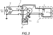
- FIG. 3 is a diagram showing an insulation resistance monitoring device 110 of the comparative example.
- the insulation resistance monitoring device 110 of the comparative example is different from the insulation resistance monitoring device 100 of the present embodiment in that the switch 31 is composed of a semiconductor switch such as an FET.
- the connection path is opened by the switch 31. Then, as shown in Fig. 3 , the probe 200a of the megger tester 200 is brought into contact with the ground line of the motor 40, the probe 200b is brought into contact with the power supply line of the motor 40, and then a megger voltage of about 500 V is applied. As a result, a current flows from the power supply line of the motor 40 to the ground line in the direction indicated by the arrow A, and the insulation resistance of the motor 40 can be measured.
- the switch 30 in the insulation resistance monitoring device 110 of the comparative example is a semiconductor switch, the off resistance when the connection path between the power supply line or the ground line of the motor 40 and the voltage generating unit 20 is opened is about 1 M ⁇ . Therefore, when the probes 200a and 200b of the mega tester 200 are brought into contact with the power supply line and the ground line of the motor 40 as described above, the current due to the megger voltage leaks to the insulation resistance monitoring device 110 side as shown by the arrow B in Fig. 3 .
- the insulation resistance monitoring device 110 of the comparative example it is necessary to remove the insulation resistance monitoring device 110 from the motor 40 when measuring the insulation resistance using the mega tester 200.
- the insulation resistance can be measured by the mega tester 200 without removing the insulation resistance monitoring device 100 from the motor 40.
Landscapes
- Physics & Mathematics (AREA)
- General Physics & Mathematics (AREA)
- Testing Of Short-Circuits, Discontinuities, Leakage, Or Incorrect Line Connections (AREA)
- Measurement Of Resistance Or Impedance (AREA)
- Tests Of Circuit Breakers, Generators, And Electric Motors (AREA)
Claims (4)
- Dispositif de surveillance de résistance d'isolation (100) permettant de surveiller une résistance d'isolation d'un objet (40) à mesurer, une valeur normale de la résistance d'isolation étant d'environ 100 MΩ, l'objet étant connecté à une masse par l'intermédiaire d'une ligne de masse et commandé par une tension d'environ 200 à 480 VCA appliquée par l'intermédiaire d'une ligne d'alimentation électrique, ledit dispositif de surveillance de résistance d'isolation (100) comprenant :une unité de détection de courant (10) qui est configurée pour être connectée entre la ligne d'alimentation électrique et la ligne de masse de l'objet (40) à mesurer et qui est configurée pour détecter un courant circulant à travers la résistance d'isolation de l'objet (40) à mesurer ;une unité de génération de tension (20) qui est configurée pour être connectée entre la ligne d'alimentation électrique et la ligne de masse de l'objet (40) à mesurer et qui est configurée pour générer une tension d'environ 500 VCC pour fournir la tension à l'objet par l'intermédiaire de la ligne d'alimentation électrique ; etun commutateur (30) configuré pour ouvrir et fermer un chemin de connexion entre la ligne d'alimentation électrique ou la ligne de masse de l'objet (40) à mesurer et l'unité de génération de tension (20), le dispositif étant en outre configuré pour que la résistance d'isolation de l'objet (40) puisse être mesurée par un méga-testeur (200) connecté entre la ligne d'alimentation électrique et la ligne de masse,lorsque ledit chemin de connexion est fermé par le commutateur (30) dans un état où une alimentation électrique à travers la ligne d'alimentation électrique vers l'objet (40) est arrêtée et que ladite unité de génération de tension (20) génère une tension d'environ 500 VCC pour fournir la tension à l'objet (40) par l'intermédiaire de la ligne d'alimentation électrique, ladite unité de détection de courant (10) étant configurée pour délivrer une sortie indiquant une anomalie si la valeur de résistance d'isolation calculée sur la base d'un courant détecté par l'unité de détection de courant (10) est en dehors d'une plage de la valeur normale,lorsque ladite résistance d'isolation de l'objet (40) est mesurée par un méga-testeur (200) connecté entre la ligne d'alimentation électrique et la ligne de masse pour une inspection légale, ledit chemin de connexion étant ouvert par le commutateur (30) dans un état où une alimentation électrique à travers la ligne d'alimentation électrique vers l'objet (40) est arrêtée, ledit commutateur (30) comportant une résistance d'arrêt de 100 MΩ ou plus lorsque le chemin de connexion est ouvert.
- Dispositif de surveillance de résistance d'isolation (100) selon la revendication 1, caractérisé en ce que le commutateur (30) comporte une résistance d'arrêt de 1000 MΩ ou plus lorsque le chemin de connexion est ouvert.
- Dispositif de surveillance de résistance d'isolation (100) selon la revendication 1 ou 2, caractérisé en ce que le commutateur (30) est un relais à lame vibrante.
- Dispositif de surveillance de résistance d'isolation (100) selon la revendication 1 ou 2, caractérisé en ce que le commutateur (30) est un commutateur mécanique.
Applications Claiming Priority (2)
| Application Number | Priority Date | Filing Date | Title |
|---|---|---|---|
| JP2019048909A JP2020148736A (ja) | 2019-03-15 | 2019-03-15 | 絶縁抵抗監視装置 |
| PCT/JP2020/002570 WO2020189012A1 (fr) | 2019-03-15 | 2020-01-24 | Dispositif de surveillance de résistance d'isolation |
Publications (3)
| Publication Number | Publication Date |
|---|---|
| EP3940407A1 EP3940407A1 (fr) | 2022-01-19 |
| EP3940407A4 EP3940407A4 (fr) | 2022-12-21 |
| EP3940407B1 true EP3940407B1 (fr) | 2025-05-28 |
Family
ID=72429458
Family Applications (1)
| Application Number | Title | Priority Date | Filing Date |
|---|---|---|---|
| EP20774736.1A Active EP3940407B1 (fr) | 2019-03-15 | 2020-01-24 | Dispositif de surveillance de résistance d'isolation |
Country Status (5)
| Country | Link |
|---|---|
| US (1) | US11740271B2 (fr) |
| EP (1) | EP3940407B1 (fr) |
| JP (1) | JP2020148736A (fr) |
| CN (1) | CN113544523A (fr) |
| WO (1) | WO2020189012A1 (fr) |
Families Citing this family (2)
| Publication number | Priority date | Publication date | Assignee | Title |
|---|---|---|---|---|
| JP7585722B2 (ja) * | 2020-11-09 | 2024-11-19 | オムロン株式会社 | 絶縁抵抗監視装置 |
| JP7615831B2 (ja) | 2021-03-29 | 2025-01-17 | オムロン株式会社 | 絶縁抵抗監視装置 |
Family Cites Families (18)
| Publication number | Priority date | Publication date | Assignee | Title |
|---|---|---|---|---|
| JPS58116018A (ja) * | 1981-12-26 | 1983-07-11 | マリ−ン・セイフ・エレクトロニクス・オブ・カナダ・リミテツド | モ−タ用巻線保護安全装置 |
| JPS60153657U (ja) * | 1984-03-23 | 1985-10-14 | 倉茂電工株式会社 | 絶縁劣化検知装置付電動機 |
| JPH08201469A (ja) * | 1995-01-31 | 1996-08-09 | East Japan Railway Co | 絶縁監視装置 |
| JP3163016B2 (ja) * | 1996-10-14 | 2001-05-08 | 協同組合ジョイント・ラボ・仙台 | 電磁雑音測定装置 |
| JP4199559B2 (ja) * | 2003-02-19 | 2008-12-17 | 株式会社アピステ | 三相誘導モータ絶縁劣化監視装置 |
| JP4003137B2 (ja) * | 2004-02-20 | 2007-11-07 | 株式会社デンソー | 地絡検出装置 |
| JP4855057B2 (ja) * | 2005-12-06 | 2012-01-18 | ファナック株式会社 | モータ駆動装置 |
| JP2008157672A (ja) * | 2006-12-21 | 2008-07-10 | Fanuc Ltd | モータの絶縁劣化検出装置 |
| DE102007046483B4 (de) * | 2007-09-28 | 2014-02-27 | Continental Automotive Gmbh | Schaltungsanordnung und Verfahren zur Überwachung einer elektrischen Isolation |
| US8319503B2 (en) * | 2008-11-24 | 2012-11-27 | Cascade Microtech, Inc. | Test apparatus for measuring a characteristic of a device under test |
| JP5631656B2 (ja) * | 2010-08-09 | 2014-11-26 | 中国電力株式会社 | 絶縁低下監視装置 |
| US8766653B2 (en) * | 2011-03-15 | 2014-07-01 | Automotive Research & Testing Center | Measuring device for measuring insulation resistance of an electric vehicle |
| JP5942241B2 (ja) | 2011-08-24 | 2016-06-29 | パナソニックIpマネジメント株式会社 | 情報配信システム、システム制御装置 |
| JP2016031298A (ja) * | 2014-07-29 | 2016-03-07 | 株式会社豊田自動織機 | 絶縁異常検知装置 |
| JP2017062168A (ja) * | 2015-09-25 | 2017-03-30 | 株式会社豊田自動織機 | 漏電検知回路 |
| JP6373296B2 (ja) | 2016-03-24 | 2018-08-15 | 株式会社竹中電機 | 絶縁抵抗監視装置およびその監視制御方法ならびに電動制御機器 |
| JP6633560B2 (ja) * | 2017-02-07 | 2020-01-22 | 矢崎総業株式会社 | 地絡検出装置 |
| CN107064641A (zh) | 2017-06-09 | 2017-08-18 | 伍俊 | 高压绝缘电阻在线监测报警仪及工作方法 |
-
2019
- 2019-03-15 JP JP2019048909A patent/JP2020148736A/ja active Pending
-
2020
- 2020-01-24 WO PCT/JP2020/002570 patent/WO2020189012A1/fr not_active Ceased
- 2020-01-24 US US17/437,231 patent/US11740271B2/en active Active
- 2020-01-24 CN CN202080018669.7A patent/CN113544523A/zh active Pending
- 2020-01-24 EP EP20774736.1A patent/EP3940407B1/fr active Active
Also Published As
| Publication number | Publication date |
|---|---|
| CN113544523A (zh) | 2021-10-22 |
| US20220170970A1 (en) | 2022-06-02 |
| WO2020189012A1 (fr) | 2020-09-24 |
| JP2020148736A (ja) | 2020-09-17 |
| EP3940407A4 (fr) | 2022-12-21 |
| US11740271B2 (en) | 2023-08-29 |
| EP3940407A1 (fr) | 2022-01-19 |
Similar Documents
| Publication | Publication Date | Title |
|---|---|---|
| Lee et al. | An online groundwall and phase-to-phase insulation quality assessment technique for AC-machine stator windings | |
| US10027105B2 (en) | Overcurrent protection device and method | |
| Yang et al. | A stator winding insulation condition monitoring technique for inverter-fed machines | |
| EP3940407B1 (fr) | Dispositif de surveillance de résistance d'isolation | |
| EP1430317B1 (fr) | Commutateur a prises multiples de mesure de reponse de frequence et de decharge partielle | |
| WO2022097312A1 (fr) | Dispositif de surveillance de résistance d'isolation | |
| KR100823724B1 (ko) | 인버터 구동 교류전동기의 고정자권선 절연 진단장치 및방법 | |
| Kane et al. | Practical experiences of on-line partial discharge measurements on a variety of medium voltage electrical equipment | |
| KR20180136808A (ko) | 접지 안전성 측정 기능을 구비한 gis용 접지개폐기 | |
| RU2660221C2 (ru) | Способ и система тестирования распределительного устройства, предназначенного для использования в установках для передачи электроэнергии | |
| KR100927462B1 (ko) | 차단기 진단장치가 내장된 수배전반 및 차단기 진단 방법 | |
| Zajadatz et al. | Partial discharge diagnostics on medium-voltage switchgears measurement methods and benefits | |
| Hussain et al. | Predicting arc faults in distribution switchgears | |
| Malamov et al. | Diagnostics of High Voltage Gas-Insulated Circuit Breakers Switching System | |
| KR102953212B1 (ko) | 제2감지센서부 접점이 있는 가스절연 개폐 장치의 접지상태 감지센서를 이용한 감시장치 | |
| US20160161558A1 (en) | Testing Apparatus Usable With Circuit Interruption Apparatus | |
| KR102953211B1 (ko) | 제1감지센서부 접점이 있는 가스절연 개폐 장치의 접지상태 감지센서를 이용한 감시장치 | |
| JP4728797B2 (ja) | ガス絶縁電力機器 | |
| JP7443181B2 (ja) | 耐電圧試験装置 | |
| TWI485736B (zh) | Vacuum switch and vacuum insulated switchgear | |
| Manzano Fernández et al. | Detection of open phase condition in power transformers | |
| Smith et al. | Experience with on-line partial discharge analysis as a tool for predictive maintenance for medium voltage (MV) switchgear systems | |
| Riechert et al. | Monitoring and diagnostics of gas-insulated switchgear–development trends and range of applications | |
| Weber et al. | Field Measurements of Partial Discharges in Potential Transformers | |
| KR20260006296A (ko) | 유전율을 이용한 개폐장치 vi 진단 장치 및 방법 |
Legal Events
| Date | Code | Title | Description |
|---|---|---|---|
| STAA | Information on the status of an ep patent application or granted ep patent |
Free format text: STATUS: THE INTERNATIONAL PUBLICATION HAS BEEN MADE |
|
| PUAI | Public reference made under article 153(3) epc to a published international application that has entered the european phase |
Free format text: ORIGINAL CODE: 0009012 |
|
| STAA | Information on the status of an ep patent application or granted ep patent |
Free format text: STATUS: REQUEST FOR EXAMINATION WAS MADE |
|
| 17P | Request for examination filed |
Effective date: 20210826 |
|
| AK | Designated contracting states |
Kind code of ref document: A1 Designated state(s): AL AT BE BG CH CY CZ DE DK EE ES FI FR GB GR HR HU IE IS IT LI LT LU LV MC MK MT NL NO PL PT RO RS SE SI SK SM TR |
|
| DAV | Request for validation of the european patent (deleted) | ||
| DAX | Request for extension of the european patent (deleted) | ||
| A4 | Supplementary search report drawn up and despatched |
Effective date: 20221123 |
|
| RIC1 | Information provided on ipc code assigned before grant |
Ipc: G01R 31/34 20200101ALI20221117BHEP Ipc: G01R 31/50 20200101AFI20221117BHEP |
|
| REG | Reference to a national code |
Ref country code: DE Ref legal event code: R079 Free format text: PREVIOUS MAIN CLASS: G01R0031500000 Ipc: G01R0027020000 Ref country code: DE Ref legal event code: R079 Ref document number: 602020052032 Country of ref document: DE Free format text: PREVIOUS MAIN CLASS: G01R0031500000 Ipc: G01R0027020000 |
|
| GRAP | Despatch of communication of intention to grant a patent |
Free format text: ORIGINAL CODE: EPIDOSNIGR1 |
|
| STAA | Information on the status of an ep patent application or granted ep patent |
Free format text: STATUS: GRANT OF PATENT IS INTENDED |
|
| RIC1 | Information provided on ipc code assigned before grant |
Ipc: G01R 31/34 20200101ALI20241205BHEP Ipc: G01R 31/52 20200101ALI20241205BHEP Ipc: G01R 27/02 20060101AFI20241205BHEP |
|
| INTG | Intention to grant announced |
Effective date: 20241219 |
|
| GRAS | Grant fee paid |
Free format text: ORIGINAL CODE: EPIDOSNIGR3 |
|
| GRAA | (expected) grant |
Free format text: ORIGINAL CODE: 0009210 |
|
| STAA | Information on the status of an ep patent application or granted ep patent |
Free format text: STATUS: THE PATENT HAS BEEN GRANTED |
|
| AK | Designated contracting states |
Kind code of ref document: B1 Designated state(s): AL AT BE BG CH CY CZ DE DK EE ES FI FR GB GR HR HU IE IS IT LI LT LU LV MC MK MT NL NO PL PT RO RS SE SI SK SM TR |
|
| REG | Reference to a national code |
Ref country code: GB Ref legal event code: FG4D |
|
| REG | Reference to a national code |
Ref country code: CH Ref legal event code: EP |
|
| REG | Reference to a national code |
Ref country code: IE Ref legal event code: FG4D Ref country code: DE Ref legal event code: R096 Ref document number: 602020052032 Country of ref document: DE |
|
| REG | Reference to a national code |
Ref country code: NL Ref legal event code: MP Effective date: 20250528 |
|
| PG25 | Lapsed in a contracting state [announced via postgrant information from national office to epo] |
Ref country code: FI Free format text: LAPSE BECAUSE OF FAILURE TO SUBMIT A TRANSLATION OF THE DESCRIPTION OR TO PAY THE FEE WITHIN THE PRESCRIBED TIME-LIMIT Effective date: 20250528 Ref country code: ES Free format text: LAPSE BECAUSE OF FAILURE TO SUBMIT A TRANSLATION OF THE DESCRIPTION OR TO PAY THE FEE WITHIN THE PRESCRIBED TIME-LIMIT Effective date: 20250528 |
|
| REG | Reference to a national code |
Ref country code: LT Ref legal event code: MG9D |
|
| PG25 | Lapsed in a contracting state [announced via postgrant information from national office to epo] |
Ref country code: NO Free format text: LAPSE BECAUSE OF FAILURE TO SUBMIT A TRANSLATION OF THE DESCRIPTION OR TO PAY THE FEE WITHIN THE PRESCRIBED TIME-LIMIT Effective date: 20250828 Ref country code: GR Free format text: LAPSE BECAUSE OF FAILURE TO SUBMIT A TRANSLATION OF THE DESCRIPTION OR TO PAY THE FEE WITHIN THE PRESCRIBED TIME-LIMIT Effective date: 20250829 |
|
| PG25 | Lapsed in a contracting state [announced via postgrant information from national office to epo] |
Ref country code: NL Free format text: LAPSE BECAUSE OF FAILURE TO SUBMIT A TRANSLATION OF THE DESCRIPTION OR TO PAY THE FEE WITHIN THE PRESCRIBED TIME-LIMIT Effective date: 20250528 Ref country code: PL Free format text: LAPSE BECAUSE OF FAILURE TO SUBMIT A TRANSLATION OF THE DESCRIPTION OR TO PAY THE FEE WITHIN THE PRESCRIBED TIME-LIMIT Effective date: 20250528 |
|
| PG25 | Lapsed in a contracting state [announced via postgrant information from national office to epo] |
Ref country code: BG Free format text: LAPSE BECAUSE OF FAILURE TO SUBMIT A TRANSLATION OF THE DESCRIPTION OR TO PAY THE FEE WITHIN THE PRESCRIBED TIME-LIMIT Effective date: 20250528 |
|
| PG25 | Lapsed in a contracting state [announced via postgrant information from national office to epo] |
Ref country code: HR Free format text: LAPSE BECAUSE OF FAILURE TO SUBMIT A TRANSLATION OF THE DESCRIPTION OR TO PAY THE FEE WITHIN THE PRESCRIBED TIME-LIMIT Effective date: 20250528 |
|
| PG25 | Lapsed in a contracting state [announced via postgrant information from national office to epo] |
Ref country code: RS Free format text: LAPSE BECAUSE OF FAILURE TO SUBMIT A TRANSLATION OF THE DESCRIPTION OR TO PAY THE FEE WITHIN THE PRESCRIBED TIME-LIMIT Effective date: 20250828 |
|
| PG25 | Lapsed in a contracting state [announced via postgrant information from national office to epo] |
Ref country code: IS Free format text: LAPSE BECAUSE OF FAILURE TO SUBMIT A TRANSLATION OF THE DESCRIPTION OR TO PAY THE FEE WITHIN THE PRESCRIBED TIME-LIMIT Effective date: 20250928 |
|
| PG25 | Lapsed in a contracting state [announced via postgrant information from national office to epo] |
Ref country code: LV Free format text: LAPSE BECAUSE OF FAILURE TO SUBMIT A TRANSLATION OF THE DESCRIPTION OR TO PAY THE FEE WITHIN THE PRESCRIBED TIME-LIMIT Effective date: 20250528 |
|
| REG | Reference to a national code |
Ref country code: AT Ref legal event code: MK05 Ref document number: 1798870 Country of ref document: AT Kind code of ref document: T Effective date: 20250528 |
|
| PG25 | Lapsed in a contracting state [announced via postgrant information from national office to epo] |
Ref country code: AT Free format text: LAPSE BECAUSE OF FAILURE TO SUBMIT A TRANSLATION OF THE DESCRIPTION OR TO PAY THE FEE WITHIN THE PRESCRIBED TIME-LIMIT Effective date: 20250528 Ref country code: SM Free format text: LAPSE BECAUSE OF FAILURE TO SUBMIT A TRANSLATION OF THE DESCRIPTION OR TO PAY THE FEE WITHIN THE PRESCRIBED TIME-LIMIT Effective date: 20250528 Ref country code: DK Free format text: LAPSE BECAUSE OF FAILURE TO SUBMIT A TRANSLATION OF THE DESCRIPTION OR TO PAY THE FEE WITHIN THE PRESCRIBED TIME-LIMIT Effective date: 20250528 |
|
| PG25 | Lapsed in a contracting state [announced via postgrant information from national office to epo] |
Ref country code: CZ Free format text: LAPSE BECAUSE OF FAILURE TO SUBMIT A TRANSLATION OF THE DESCRIPTION OR TO PAY THE FEE WITHIN THE PRESCRIBED TIME-LIMIT Effective date: 20250528 |
|
| PG25 | Lapsed in a contracting state [announced via postgrant information from national office to epo] |
Ref country code: EE Free format text: LAPSE BECAUSE OF FAILURE TO SUBMIT A TRANSLATION OF THE DESCRIPTION OR TO PAY THE FEE WITHIN THE PRESCRIBED TIME-LIMIT Effective date: 20250528 |
|
| PG25 | Lapsed in a contracting state [announced via postgrant information from national office to epo] |
Ref country code: SK Free format text: LAPSE BECAUSE OF FAILURE TO SUBMIT A TRANSLATION OF THE DESCRIPTION OR TO PAY THE FEE WITHIN THE PRESCRIBED TIME-LIMIT Effective date: 20250528 |
|
| PG25 | Lapsed in a contracting state [announced via postgrant information from national office to epo] |
Ref country code: IT Free format text: LAPSE BECAUSE OF FAILURE TO SUBMIT A TRANSLATION OF THE DESCRIPTION OR TO PAY THE FEE WITHIN THE PRESCRIBED TIME-LIMIT Effective date: 20250528 |
|
| REG | Reference to a national code |
Ref country code: DE Ref legal event code: R097 Ref document number: 602020052032 Country of ref document: DE |
|
| PLBE | No opposition filed within time limit |
Free format text: ORIGINAL CODE: 0009261 |
|
| STAA | Information on the status of an ep patent application or granted ep patent |
Free format text: STATUS: NO OPPOSITION FILED WITHIN TIME LIMIT |
|
| REG | Reference to a national code |
Ref country code: CH Ref legal event code: L10 Free format text: ST27 STATUS EVENT CODE: U-0-0-L10-L00 (AS PROVIDED BY THE NATIONAL OFFICE) Effective date: 20260409 |