EP3940324B1 - Griffanordnung und haushaltsgerät damit - Google Patents
Griffanordnung und haushaltsgerät damit Download PDFInfo
- Publication number
- EP3940324B1 EP3940324B1 EP19923291.9A EP19923291A EP3940324B1 EP 3940324 B1 EP3940324 B1 EP 3940324B1 EP 19923291 A EP19923291 A EP 19923291A EP 3940324 B1 EP3940324 B1 EP 3940324B1
- Authority
- EP
- European Patent Office
- Prior art keywords
- handle
- groove
- limiting
- boss
- retractable element
- Prior art date
- Legal status (The legal status is an assumption and is not a legal conclusion. Google has not performed a legal analysis and makes no representation as to the accuracy of the status listed.)
- Active
Links
Images


Classifications
-
- E—FIXED CONSTRUCTIONS
- E05—LOCKS; KEYS; WINDOW OR DOOR FITTINGS; SAFES
- E05B—LOCKS; ACCESSORIES THEREFOR; HANDCUFFS
- E05B65/00—Locks or fastenings for special use
- E05B65/0042—For refrigerators or cold rooms
-
- F—MECHANICAL ENGINEERING; LIGHTING; HEATING; WEAPONS; BLASTING
- F25—REFRIGERATION OR COOLING; COMBINED HEATING AND REFRIGERATION SYSTEMS; HEAT PUMP SYSTEMS; MANUFACTURE OR STORAGE OF ICE; LIQUEFACTION SOLIDIFICATION OF GASES
- F25D—REFRIGERATORS; COLD ROOMS; ICE-BOXES; COOLING OR FREEZING APPARATUS NOT OTHERWISE PROVIDED FOR
- F25D23/00—General constructional features
- F25D23/02—Doors; Covers
- F25D23/028—Details
-
- E—FIXED CONSTRUCTIONS
- E05—LOCKS; KEYS; WINDOW OR DOOR FITTINGS; SAFES
- E05B—LOCKS; ACCESSORIES THEREFOR; HANDCUFFS
- E05B1/00—Knobs or handles for wings; Knobs, handles, or press buttons for locks or latches on wings
- E05B1/0015—Knobs or handles which do not operate the bolt or lock, e.g. non-movable; Mounting thereof
-
- E—FIXED CONSTRUCTIONS
- E05—LOCKS; KEYS; WINDOW OR DOOR FITTINGS; SAFES
- E05B—LOCKS; ACCESSORIES THEREFOR; HANDCUFFS
- E05B3/00—Fastening knobs or handles to lock or latch parts
Definitions
- This application relates to the field of household appliances, and more particularly to, a handle assembly and a household appliance having same.
- handles of household appliances are generally mounted in a visible manner, that is, handles are fixed on doors through fixing screws. After the visible handle is mounted on the household appliance, a packaging volume of the whole household appliance is increased, which reduces the number of household appliances that may be transported in unchanged space. Especially for export-oriented household appliances, the freight of a single container is fixed and expensive.
- handles will not be mounted on the household appliances until the household appliances have been transported to users' houses, to reduce the volume of a single household appliance.
- the existing handles can only be mounted by using special tools, they need to be mounted at home by after-sales personnel, which leads to an increase in the cost of the household appliances. Relevant prior art can be found in KR 2003 0003588 A .
- the present invention aims to solve one of the above technical problems in the related art at least to a certain degree. Accordingly, the present invention proposes a handle assembly, which can be mounted on a door conveniently and reliably without the help of other special tools.
- the handle assembly includes a mounting assembly including a pre-mounted member and a retractable element, in which a handle groove is arranged in the pre-mounted member, and the retractable element at least partially extends into the handle groove; and a handle including a limiting boss, in which the limiting boss is configured to be arranged in the handle groove and includes a limiting groove, and the limiting groove is configured to secure the handle under the condition that the retractable element extends into the limiting groove.
- the handle includes the limiting boss, the limiting boss includes the limiting groove, and the pre-mounted member of the mounting assembly includes the handle groove, such that the mounting of the handle and the pre-mounted member may be realized by the fitting between the limiting boss and the handle groove.
- a part of the retractable element of the mounting assembly extends into the limiting groove and lock the handle, to ensure high reliability of installation of the handle.
- the user may install the handle onto the object on which the handle needs to be mounted without using other special tools, which enhances user experience and makes the installation of the handle easy and reliable.
- a clamping slot is arranged on the pre-mounted member and in communication with the handle groove, and the retractable element is configured to move in the clamping slot.
- the mounting assembly further includes an elastic element coupled to the retractable element and configured to push the retractable element towards the handle groove.
- the retractable element has an inclined guide surface, in which the inclined guide surface is configured in such a way that the handle presses the inclined guide surface and the retractable element is retracted from the handle groove when the handle moves along the handle groove towards the retractable element; the retractable element is configured to enter the limiting groove from the clamping slot under an elastic force of the elastic element when the limiting groove is aligned with the clamping slot.
- the handle groove has a first and a second limiting step; and the limiting boss is a T-shaped boss and includes a long boss and a short boss, in which the long boss is configured to move in the handle groove, and the short boss is configured to be clamped between the first and second limiting steps when the limiting groove is aligned with the clamping slot.
- an inner surface of the first and second limiting steps is spaced apart from a groove bottom of the handle groove.
- a height of the first and second limiting steps is at least greater than a half of a height of the long boss.
- the mounting assembly further includes a retaining cap configured to confine the elastic element in the clamping slot.
- the elastic element is a spring.
- the household appliance according to embodiments of another aspect of the present disclosure includes a door and the above handle assembly arranged on the door.
- the pre-mounted member is integrated with the door.
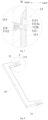
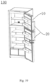
- refrigerator 100 door 10, mounting assembly 11, pre-mounted member 111, handle groove 1111, limiting step 1111a, clamping slot 1112, retractable element 112, inclined guide surface 112b, retaining cap 113, elastic element 114, handle 20, limiting boss 21, long boss 211, short boss 212, limiting groove 213.
- the handle assembly includes: a mounting assembly 11 and a handle 20 that is fitted with the mounting assembly 11.
- the mounting assembly 11 includes: a pre-mounted member 111 and a retractable element 112.
- the pre-mounted member may be pre-mounted on an object on which the handle 20 is to be mounted.
- the mounting assembly 11 may be located on a door 10 of the household appliance, and the pre-mounted member 111 is fixedly coupled to the door 10.
- the pre-mounted member 111 may be pre-embedded in a foam layer of the door 10.
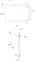
- a handle groove 1111 is arranged in the pre-mounted member 111.
- the handle groove 1111 is located at each of an upper end and a lower end of the pre-mounted member 111, and the retractable element 112 may at least partially extend into the handle groove 111.
- the mounting assembly 11 is located on an inner side of the door 10, and the handle groove 1111 is exposed on an outer side of the door 10.
- the handle 20 may be mounted on the door 10 of the household appliance by being fitted with the mounting assembly 11. A user may pull the door 10 via the handle 20, so that the household appliance may be opened or closed, which facilitates the use of the household appliance.
- the installation of the handle assembly is illustrated by exemplified the household appliance as a refrigerator 100.
- the pre-mounted member 111 may be pre-mounted in an inner foam layer of the door 10 to provide support for arranging the retractable element 112 and a retaining cap 113, and the handle groove 1111 may be exposed on an outer side of the door 10 to provide the possibility of fixing the handle 20 on the door 10.
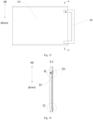
- a limiting boss 21 is arranged on the handle 20, and the limiting boss 21 is suitable for being arranged in the handle groove 1111.
- the retractable element 112 at least partially extends into the handle groove 1111, the handle 20 includes the limiting boss 21, and the limiting boss 21 is arranged in the corresponding handle groove 1111 and is movable in an up-down direction in the handle groove 1111.
- the limiting boss 21 is arranged at each of an upper end and a lower end of the handle 20, and a distance between the limiting bosses 21 at the upper and lower ends of the handle 20 is equal to a distance between the handle grooves 1111 at the upper and lower ends of the pre-mounted member 111, to ensure that the limiting bosses 21 at the upper and lower ends of the handle 20 may be successfully fitted with the handle grooves 1111 at the upper and lower ends of the pre-mounted member 111, to fix the handle 20 firmly.
- a limiting groove 213 is arranged in the limiting boss 21 and configured to secure the handle 20 under the condition that the retractable element 112 extends into the limiting groove 213.
- the limiting groove 213 is a through hole running through the limiting boss 21.
- the limiting boss 21 moves downward in the handle groove 1111, the retractable element 112 extends into the limiting groove 213, and meanwhile the handle 20 is secured. That is, at least one of the limiting bosses 21 at the upper and lower ends of the handle 20 includes the limiting groove 213.
- the limiting groove 213 is provided only at the upper end of the handle 20, or the limiting groove 213 is provided only at the lower end of the handle 20, or limiting grooves 213 are provided at both of the upper and lower ends of the handle 20.
- the cooperation process of the handle 20 and the door 10 is illustrated via an example where the limiting groove 213 is arranged only at the upper end of the handle 20 and the handle 20 is arranged along a vertical direction, as shown in Figs. 8-18 .
- the handle 20 and the door 10 are separate.
- the limiting bosses 21 at the upper and lower ends of the handle 20 are fitted with the handle grooves 1111 at the upper and lower ends which are exposed on the outer side of the door 10; the handle 20 is moved downward (i.e., being moved along the handle groove 1111 towards the retractable element 112 as described below); and at this time, the limiting groove 213 of the limiting boss 21 at the upper end of the handle 20 is aligned with the retractable element 112, and a part of the retractable element 112 extends into the limiting groove 213, limiting movement of the limiting boss 21 in the up-down direction, and restricting the limiting boss 21 of the handle 20 in the handle groove 1111 (i.e., the limiting boss 21 is locked), which may prevent the handle 20 from falling off the handle groove 1111. In such a way, the installation of the handle 20 is completed.
- a fine rod capable of extending into the limiting groove 213 can be utilized.
- the fine rod extends into the limiting groove 213 to make the retractable element 112 retracted from the handle groove 1111 and thus the limiting groove 213, so that the handle 20 is withdrawn from the handle groove 1111. In such a way, the dismounting of the handle 20 is completed.
- the handle 20 includes the limiting boss 21, the limiting boss 21 includes the limiting groove 213, and the pre-mounted member 111 of the mounting assembly 11 includes the handle groove 1111, such that the mounting of the handle 20 and the pre-mounted member is realized by the fitting between the limiting boss 21 and the handle groove 1111. Moreover, a part of the retractable element 112 of the mounting assembly 11 extends into the limiting groove 213 and lock the handle 20, to ensure high reliability of installation of the handle 20. Thus, the user may install the handle 20 onto the object on which the handle needs to be mounted (such as the door 10) without using other special tools, which enhances user experience and makes the installation of the handle 20 easy and reliable.
- a clamping slot 1112 is arranged on the pre-mounted member 111, the clamping slot 1112 is in communication with the handle groove 1111, and an axis direction of the clamping slot 1112 is perpendicular to a section of the handle groove 1111.
- the retractable element 112 is suitable to move in the clamping slot 1112 and at least partially extends into the handle groove 1111.
- a moving track is provided for the retractable element 112 and can guide a moving direction of the retractable element 112, and a part of the retractable element 112 also extends into the handle groove 1111, thus allowing the retractable element 112 to extend into the limiting groove 213.
- the clamping slot 1112 By providing the clamping slot 1112, the moving direction of the retractable element 112 may be ensured, so that the retractable element 112 may lock the limiting boss 21, ensuring high reliability of the handle assembly.
- the mounting assembly 11 also includes an elastic element 114.
- the elastic element 114 is an elastic part.
- the elastic element 114 is always in a compressed state when it is located in the mounting assembly 11.
- the elastic element 114 is connected with the retractable element 112 and is used to push the retractable element 112 towards the handle groove 1111. That is, the elastic element 114 is also located in the clamping slot 1112 and is in contact and connection with the retractable element 112. Under an elastic force of the elastic element 114, the retractable element 112 is pushed towards the handle groove 1111, and a part of the retractable element 112 is pushed into the handle groove 1111.
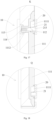
- the retractable element 112 has an inclined guide surface 112b.
- the inclined guide surface 112b is configured as follows: the handle 20 presses the inclined guide surface 112b when the handle 20 moves along the handle groove 1111 towards the retractable element 112, so that the retractable element 112 is retracted from the handle groove 1111.
- the retractable element 112 is configured to enter the limiting groove 213 from the clamping slot 1112 under the elastic force of the elastic element 114 when the limiting groove 213 is aligned with the clamping slot 1112.
- the inclined guide surface 112b is arranged at an end of the retractable element 112 which extends into the handle groove 1111.
- the inclined guide surface 112b extends obliquely in a direction toward a lower and outer side of the refrigerator 100.
- the retractable element 112 Since an extension direction of the inclined guide surface 112b is orientated obliquely toward the lower and outer side of the refrigerator 100, the retractable element 112 is subjected to a force component in a direction toward the inner side of the door 10. As a result, the retractable element 112 moves to the inner side of the door 10 and retracts from the handle groove 1111. At this time, the elastic element 114 is further compressed. As the handle 20 moves further downward, the retractable element 112 is aligned with the limiting groove 213 of the handle 20, and the retractable element 112 is pushed into the limiting groove 213 under the elastic effect of the elastic element 114. In such a way, the installation of the handle 20 is completed.
- the retractable element 112 By arranging the inclined guide surface 112b on the retractable element, the retractable element 112 can be guided when pressed by the limiting boss 21, to ensure that the retractable element 112 retracts from the handle groove 1111, so that the handle 20 may move downward to an installation position and the retractable element 112 extends into the limiting groove 213, thereby completing the installation of the handle 20.
- the handle groove 1111 has a limiting step 1111a, that is, the handle groove 1111 is a groove with the step, and a hollow inverted snap structure is arranged in the position of the limiting step 1 1 1 1a.
- the limiting boss is a T-shaped boss 21, and the T-shaped boss 21 includes: a long boss 211 and a short boss 212 fixedly connected with each other.
- a length of the long boss 211 is greater than a length of the short boss 212, and both ends of the short boss 212 are fixedly connected with the long boss 211 and the handle 20 respectively.
- the long boss 211 extends in a direction away from the handle 20.
- the length of the long boss 211 is less than or equal to the length of the handle groove 1111, so that the long boss 211 may enter the handle groove 1111.
- the limiting boss may also be a cross-shaped boss.
- the long boss 211 is suitable to move in the handle groove 1111, and the short boss 212 is configured to be clamped between two limiting steps 1111a when the limiting groove 213 is aligned with the clamping slot 1112. That is, when the limiting groove 213 is aligned with the clamping slot 1112, the short boss 212 is clamped between two limiting steps 1111a, so that the handle 20 may be prevented from being directly withdrawn from the handle groove 1111, and movement of the handle 20 in a front-rear direction and in a left-right direction can be limited, improving reliability of the cooperation between the handle 20 and the door 10. Since a part of the retractable element 112 is clamped in the limiting groove 213, the movement of the handle 20 in the up-down direction is limited. Accordingly, the installation of the handle 20 on the door 10 is realized.
- an inner surface of the limiting step 1111a is spaced apart from a groove bottom of the handle groove 1111, so that the long boss 211 may enter a gap between the limiting step 1111a and the groove bottom of the handle groove 1111, and the long boss 211 of the T-shaped boss 21 may be stuck in the handle groove 1111.
- a thickness of the long boss 211 is equal to or slightly smaller than the gap between the limiting step 1111a and the groove bottom of handle groove 1111, preventing the T-shaped boss 21 from shaking in the handle groove 1111.
- a height of the limiting step 1111a is at least greater than a half of a height of the long boss 211.
- the height dimension of the limiting step 1111a extending upwards is greater than a half of the height dimension of the long boss 211, to prevent the handle 20 from falling off the handle groove 1111, ensure the reliability of position limiting, and guarantee the high reliability of the installation of the handle 20.
- the mounting assembly 11 may also include: a retaining cap 113 located on an innermost side of the mounting assembly 11 and fixedly coupled to the pre-mounted member 111.
- the retaining cap 113 confines the elastic element 114 in the clamping slot 1112, to prevent the elastic element 114 from popping out from the pre-mounted member 111 toward the inner side of the door 10, and to ensure that the elastic element 114 may always be located in the clamping slot 1112, providing support for the retractable element 112.
- the elastic element 114 is a spring that has good elasticity, which may ensure that when the retractable element 112 moves towards the inner side of the door 10, the elastic element 114 is compressed and provides a force for the retractable element 112 to move to the outer side of the door 10, ensuring that the retractable element 112 may lock the handle 20 in time.
- the pre-mounted member 111 may be integrated with the door 10, that is, the handle groove 1111 is directly formed in the door 10, which omits the pre-mounted member 111, thus reducing the assembly process of the pre-mounted member 111 and the door 10, which can save the assembly time of the refrigerator 100.
- the pre-mounted member 111 and the door 10 may be fixed by foaming.
- the pre-mounted member is used as a pre-embedded member. That is, after the pre-mounted member 111 is pre-embedded in the door 10, a liquid foaming material is injected into the door 10, expands through a chemical reaction, and eventually wraps the pre-mounted member 111, so that the door 10 is cured into a stable shape.
- the household appliance includes a door 10 and a handle assembly arranged on the door 10.
- the household appliance may also be a disinfection cabinet, a microwave oven, and a baking oven, apart from the refrigerator 100 described above.
- the pre-mounted member 111 is integrated with the door 10, simplifying the installation process of the handle 20, ensuring that the handle 20 is easier to mount, and reducing the space occupied by the packaged household appliance, thus contributing to lower transportation cost.
- the mounting and dismounting processes of the handle assembly on and from the refrigerator 100 will be described in detail with reference to Figs. 1-19 .
- the pre-mounted member 111 is first mounted on the door 10, and then the limiting boss 21 of the handle 20 is inserted into the handle groove 1111 of the pre-mounted member 111.
- the position relationship between the door 10 and the handle 20 is shown in Figs. 11-14 .
- the handle 20 is moved towards a lower side of the door 10, so that the short boss 212 of the limiting boss 21 of the handle 20 slides into the limiting step 1111a, and the inclined guide surface of the retractable element 112 comes out of the handle groove 1111 under the pressure of the limiting boss 21.
- the handle 20 When the handle 20 continues to move to a limited position, the long boss 211 is stuck between the limiting step 1111a and the groove bottom of the handle groove 1111, and the retractable element 112 is aligned with the limiting groove 213 of the handle 20.
- the retractable element 112 is pushed into the limiting groove 213 under an elastic action of the elastic element 114.
- the handle 20 is mounted in position and locked, so that the installation of the handle 20 is completed.
- a fine rod capable of extending into the limiting groove 213 can be used to push the retractable element 112 out of the handle groove 1111 by extending into the limiting groove 213, and then the handle 20 is moved towards an upper side of the door 10, so that the handle 20 is withdrawn from the handle groove 1111. In such a way, the dismounting of the handle 20 is completed.
Landscapes
- Engineering & Computer Science (AREA)
- Physics & Mathematics (AREA)
- Thermal Sciences (AREA)
- Chemical & Material Sciences (AREA)
- Combustion & Propulsion (AREA)
- Mechanical Engineering (AREA)
- General Engineering & Computer Science (AREA)
- Refrigerator Housings (AREA)
- Tumbler Switches (AREA)
Claims (6)
- Griffanordnung, Folgendes umfassend:eine Montageanordnung (11), ein vormontierbares Element (111) zum Montieren an einem Objekt und ein zurückziehbares Element (112) umfassend, wobei eine Griffrille (1111) in dem vormontierbaren Element (111) angeordnet ist und sich das zurückziehbare Element (112) zumindest teilweise in die Griffrille (1111) erstreckt, undeinen Griff (20), der einen Begrenzungsbuckel (21) umfasst, wobei der Begrenzungsbuckel (21) dafür gestaltet ist, in der Griffrille (1111) angeordnet zu sein, und eine Begrenzungsrille (213) umfasst, und die Begrenzungsrille (213) dafür gestaltet ist, den Griff (20) zu sichern, wenn sich das zurückziehbare Element (112) in die Begrenzungsrille (213) erstreckt, wobei an dem vormontierbaren Element (111) und in Verbindung mit der Griffrille (1111) ein Klemmschlitz (1112) angeordnet ist, und das zurückziehbare Element (112) dafür gestaltet ist, sich in dem Klemmschlitz (1112) zu bewegen, und wobei die Griffrille (1111) einen ersten und einen zweiten Begrenzungsansatz (1111a) aufweist und der Begrenzungsbuckel (21) ein T-förmiger Buckel ist und einen langen Buckel (211) und einen kurzen Buckel (212) umfasst und wobei der lange Buckel (211) dafür gestaltet ist, sich in der Griffrille (1111) zu bewegen, und der kurze Buckel (212) dafür gestaltet ist, zwischen den ersten und den zweiten Begrenzungsansatz (1111a) geklemmt zu sein, wenn die Begrenzungsrille (213) an dem Klemmschlitz (1112) ausgerichtet ist, wobei die Montageanordnung (11) ferner ein elastisches Element (114) umfasst, das mit dem zurückziehbaren Element (112) gekoppelt und dafür gestaltet ist, das zurückziehbare Element (112) hin zur Griffrille (1111) zu drücken, und wobei das zurückziehbare Element (112) eine geneigte Führungsfläche (112b) aufweist, wobei die geneigte Führungsfläche (112b) derart gestaltet ist, dass der Griff (20) auf die geneigte Führungsfläche (112b) drückt und das zurückziehbare Element (112) von der Griffrille (1111) zurückgezogen wird, wenn sich der Griff (20) entlang der Griffrille (1111) hin zu dem zurückziehbaren Element (112) bewegt, und wobei das zurückziehbare Element (112) dafür gestaltet ist, unter einer elastischen Kraft des elastischen Elements (114) von dem Klemmschlitz (1112) aus in die Begrenzungsrille (213) einzutreten, wenn die Begrenzungsrille (213) an dem Klemmschlitz (1112) ausgerichtet ist.
- Griffanordnung nach Anspruch 1, wobei eine Innenfläche des ersten und des zweiten Begrenzungsansatzes (1111a) von einem Rillenboden der Griffrille (1111) beabstandet ist.
- Griffanordnung nach Anspruch 1, wobei eine Höhe des ersten und des zweiten Begrenzungsansatzes (1111a) mindestens mehr als die Hälfte einer Höhe des langen Buckels (211) ist.
- Griffanordnung nach Anspruch 1, wobei die Montageanordnung (11) ferner eine Haltekappe (113) umfasst, die dafür gestaltet ist, das elastische Element (114) in dem Klemmschlitz (1112) zu halten.
- Haushaltsgerät, eine Tür (10) und die Griffanordnung nach einem der Ansprüche 1 bis 4 umfassend, wobei die Montageanordnung (11) an der Tür (10) angeordnet ist.
- Haushaltsgerät nach Anspruch 5, wobei das vormontierbare Element (111) in die Tür (10) integriert ist.
Applications Claiming Priority (1)
| Application Number | Priority Date | Filing Date | Title |
|---|---|---|---|
| PCT/CN2019/080460 WO2020198950A1 (zh) | 2019-03-29 | 2019-03-29 | 把手组件及具有其的家用电器 |
Publications (3)
| Publication Number | Publication Date |
|---|---|
| EP3940324A1 EP3940324A1 (de) | 2022-01-19 |
| EP3940324A4 EP3940324A4 (de) | 2022-03-30 |
| EP3940324B1 true EP3940324B1 (de) | 2025-02-12 |
Family
ID=72664444
Family Applications (1)
| Application Number | Title | Priority Date | Filing Date |
|---|---|---|---|
| EP19923291.9A Active EP3940324B1 (de) | 2019-03-29 | 2019-03-29 | Griffanordnung und haushaltsgerät damit |
Country Status (3)
| Country | Link |
|---|---|
| US (1) | US12044035B2 (de) |
| EP (1) | EP3940324B1 (de) |
| WO (1) | WO2020198950A1 (de) |
Families Citing this family (1)
| Publication number | Priority date | Publication date | Assignee | Title |
|---|---|---|---|---|
| US20230148387A1 (en) * | 2021-11-08 | 2023-05-11 | Haier Us Appliance Solutions, Inc. | Slide and lock appliance handle mounting |
Family Cites Families (17)
| Publication number | Priority date | Publication date | Assignee | Title |
|---|---|---|---|---|
| US3484894A (en) * | 1967-12-15 | 1969-12-23 | Ltv Electrosystems Inc | Removable handle |
| KR100398501B1 (ko) * | 2001-07-03 | 2003-09-19 | 삼성전자주식회사 | 냉장고의 도어핸들 |
| DE10308629A1 (de) * | 2003-02-27 | 2004-09-09 | BSH Bosch und Siemens Hausgeräte GmbH | Türgriff |
| JP4283300B2 (ja) * | 2006-10-27 | 2009-06-24 | 三菱電機株式会社 | 冷蔵庫の扉 |
| KR100876689B1 (ko) | 2007-08-27 | 2008-12-31 | 엘지전자 주식회사 | 냉장고 및 냉장고 도어 |
| AU2008216999B2 (en) | 2007-10-25 | 2014-11-13 | Aktiebolaget Electrolux | A Handle Assembly |
| KR200464311Y1 (ko) * | 2007-11-12 | 2013-01-10 | 삼성전자주식회사 | 냉장고 |
| CN201129902Y (zh) | 2007-12-03 | 2008-10-08 | 苏州三星电子有限公司 | 冰箱门手柄装配结构 |
| CN102003108B (zh) | 2010-11-19 | 2012-10-10 | 海信科龙电器股份有限公司 | 一种可实现自锁的冰箱拉手装配结构 |
| US8732910B1 (en) * | 2013-02-28 | 2014-05-27 | General Electric Companmy | Appliance handle assembly |
| US9366471B2 (en) * | 2013-10-31 | 2016-06-14 | General Electric Company | Appliance and a handle assembly for an appliance |
| CN104633607B (zh) | 2013-11-13 | 2019-03-22 | 深圳市海洋王照明工程有限公司 | 电筒及其固定结构 |
| KR101600313B1 (ko) * | 2015-04-17 | 2016-03-21 | 삼성전자주식회사 | 냉장고 |
| JP2017106642A (ja) | 2015-12-07 | 2017-06-15 | 青島海爾股▲フン▼有限公司 | 冷蔵庫 |
| CN108193936B (zh) | 2017-12-14 | 2019-05-31 | 青岛海尔特种电冰柜有限公司 | 一种制冷设备 |
| CN209637377U (zh) * | 2018-12-05 | 2019-11-15 | 福建西河卫浴科技有限公司 | 一种拉手组件和淋浴房 |
| CN114901105B (zh) * | 2020-01-13 | 2024-08-02 | 瓦林格创新股份有限公司 | 包括利用机械锁定机构来布置的镶板和拉手的组件 |
-
2019
- 2019-03-29 EP EP19923291.9A patent/EP3940324B1/de active Active
- 2019-03-29 US US17/441,678 patent/US12044035B2/en active Active
- 2019-03-29 WO PCT/CN2019/080460 patent/WO2020198950A1/zh not_active Ceased
Also Published As
| Publication number | Publication date |
|---|---|
| WO2020198950A1 (zh) | 2020-10-08 |
| US20220145662A1 (en) | 2022-05-12 |
| EP3940324A4 (de) | 2022-03-30 |
| US12044035B2 (en) | 2024-07-23 |
| BR112021019501A2 (pt) | 2021-11-30 |
| EP3940324A1 (de) | 2022-01-19 |
Similar Documents
| Publication | Publication Date | Title |
|---|---|---|
| US20120280608A1 (en) | Refrigerator and refrigerator door | |
| US12123639B2 (en) | Refrigerator door with replaceable door panel | |
| AU2018206195B2 (en) | Refrigerator | |
| EP3940324B1 (de) | Griffanordnung und haushaltsgerät damit | |
| KR20140143016A (ko) | 이중 도어방식을 갖는 내부도어의 버튼 래치장치 | |
| US20090139260A1 (en) | Door opening and closing mechanism | |
| CN219572107U (zh) | 窗式空调器 | |
| JP2004100969A (ja) | 冷蔵庫扉 | |
| CN109881974A (zh) | 把手组件及具有其的家用电器 | |
| US10759273B2 (en) | Structure of fuel filler door for vehicle | |
| CN203629189U (zh) | 具有铰链的制冷器具 | |
| CN218525485U (zh) | 一种纽扣开关结构 | |
| CN204329447U (zh) | 冰箱门体及具有该冰箱门体的冰箱 | |
| JP5291167B2 (ja) | 回路遮断機用外部操作ハンドルのトリップボタン装置 | |
| CN110714307A (zh) | 洗涤剂投放装置、洗涤剂投放组件和洗衣机 | |
| CN210200603U (zh) | 一种按键结构及网关设备 | |
| CN113493999A (zh) | 拉手组件、洗涤剂盒及洗衣设备 | |
| CN114129113B (zh) | 一种锁止结构及洗碗机 | |
| EP3150945B1 (de) | Kühlschrank mit verriegelungsvorrichtung für eiskübel und verfahren zur installation der verriegelungsvorrichtung eines eiskübels | |
| JP2004068595A (ja) | 扉開閉機構 | |
| CN220463776U (zh) | 换挡锁定结构及电动工具 | |
| BR112021019501B1 (pt) | Conjunto de puxador e eletrodoméstico | |
| CN219037200U (zh) | 冰箱 | |
| JPH0346139Y2 (de) | ||
| US12303030B1 (en) | Drawer assembly |
Legal Events
| Date | Code | Title | Description |
|---|---|---|---|
| STAA | Information on the status of an ep patent application or granted ep patent |
Free format text: STATUS: THE INTERNATIONAL PUBLICATION HAS BEEN MADE |
|
| PUAI | Public reference made under article 153(3) epc to a published international application that has entered the european phase |
Free format text: ORIGINAL CODE: 0009012 |
|
| STAA | Information on the status of an ep patent application or granted ep patent |
Free format text: STATUS: REQUEST FOR EXAMINATION WAS MADE |
|
| 17P | Request for examination filed |
Effective date: 20211014 |
|
| AK | Designated contracting states |
Kind code of ref document: A1 Designated state(s): AL AT BE BG CH CY CZ DE DK EE ES FI FR GB GR HR HU IE IS IT LI LT LU LV MC MK MT NL NO PL PT RO RS SE SI SK SM TR |
|
| A4 | Supplementary search report drawn up and despatched |
Effective date: 20220301 |
|
| RIC1 | Information provided on ipc code assigned before grant |
Ipc: E05B 3/00 20060101ALI20220223BHEP Ipc: E05B 1/00 20060101ALI20220223BHEP Ipc: F25D 23/02 20060101AFI20220223BHEP |
|
| DAV | Request for validation of the european patent (deleted) | ||
| DAX | Request for extension of the european patent (deleted) | ||
| STAA | Information on the status of an ep patent application or granted ep patent |
Free format text: STATUS: EXAMINATION IS IN PROGRESS |
|
| 17Q | First examination report despatched |
Effective date: 20230119 |
|
| GRAP | Despatch of communication of intention to grant a patent |
Free format text: ORIGINAL CODE: EPIDOSNIGR1 |
|
| STAA | Information on the status of an ep patent application or granted ep patent |
Free format text: STATUS: GRANT OF PATENT IS INTENDED |
|
| RIC1 | Information provided on ipc code assigned before grant |
Ipc: E05B 3/00 20060101ALN20240823BHEP Ipc: E05B 1/00 20060101ALN20240823BHEP Ipc: E05B 65/00 20060101ALI20240823BHEP Ipc: F25D 23/02 20060101AFI20240823BHEP |
|
| INTG | Intention to grant announced |
Effective date: 20240918 |
|
| GRAS | Grant fee paid |
Free format text: ORIGINAL CODE: EPIDOSNIGR3 |
|
| GRAA | (expected) grant |
Free format text: ORIGINAL CODE: 0009210 |
|
| STAA | Information on the status of an ep patent application or granted ep patent |
Free format text: STATUS: THE PATENT HAS BEEN GRANTED |
|
| AK | Designated contracting states |
Kind code of ref document: B1 Designated state(s): AL AT BE BG CH CY CZ DE DK EE ES FI FR GB GR HR HU IE IS IT LI LT LU LV MC MK MT NL NO PL PT RO RS SE SI SK SM TR |
|
| REG | Reference to a national code |
Ref country code: GB Ref legal event code: FG4D |
|
| REG | Reference to a national code |
Ref country code: CH Ref legal event code: EP |
|
| REG | Reference to a national code |
Ref country code: DE Ref legal event code: R096 Ref document number: 602019065980 Country of ref document: DE |
|
| REG | Reference to a national code |
Ref country code: IE Ref legal event code: FG4D |
|
| PGFP | Annual fee paid to national office [announced via postgrant information from national office to epo] |
Ref country code: DE Payment date: 20250313 Year of fee payment: 7 |
|
| PGFP | Annual fee paid to national office [announced via postgrant information from national office to epo] |
Ref country code: FR Payment date: 20250313 Year of fee payment: 7 |
|
| PGFP | Annual fee paid to national office [announced via postgrant information from national office to epo] |
Ref country code: GB Payment date: 20250313 Year of fee payment: 7 |
|
| REG | Reference to a national code |
Ref country code: NL Ref legal event code: MP Effective date: 20250212 |
|
| PG25 | Lapsed in a contracting state [announced via postgrant information from national office to epo] |
Ref country code: RS Free format text: LAPSE BECAUSE OF FAILURE TO SUBMIT A TRANSLATION OF THE DESCRIPTION OR TO PAY THE FEE WITHIN THE PRESCRIBED TIME-LIMIT Effective date: 20250512 |
|
| PG25 | Lapsed in a contracting state [announced via postgrant information from national office to epo] |
Ref country code: FI Free format text: LAPSE BECAUSE OF FAILURE TO SUBMIT A TRANSLATION OF THE DESCRIPTION OR TO PAY THE FEE WITHIN THE PRESCRIBED TIME-LIMIT Effective date: 20250212 |
|
| PG25 | Lapsed in a contracting state [announced via postgrant information from national office to epo] |
Ref country code: PL Free format text: LAPSE BECAUSE OF FAILURE TO SUBMIT A TRANSLATION OF THE DESCRIPTION OR TO PAY THE FEE WITHIN THE PRESCRIBED TIME-LIMIT Effective date: 20250212 |
|
| PG25 | Lapsed in a contracting state [announced via postgrant information from national office to epo] |
Ref country code: ES Free format text: LAPSE BECAUSE OF FAILURE TO SUBMIT A TRANSLATION OF THE DESCRIPTION OR TO PAY THE FEE WITHIN THE PRESCRIBED TIME-LIMIT Effective date: 20250212 |
|
| REG | Reference to a national code |
Ref country code: LT Ref legal event code: MG9D |
|
| PG25 | Lapsed in a contracting state [announced via postgrant information from national office to epo] |
Ref country code: NO Free format text: LAPSE BECAUSE OF FAILURE TO SUBMIT A TRANSLATION OF THE DESCRIPTION OR TO PAY THE FEE WITHIN THE PRESCRIBED TIME-LIMIT Effective date: 20250512 Ref country code: IS Free format text: LAPSE BECAUSE OF FAILURE TO SUBMIT A TRANSLATION OF THE DESCRIPTION OR TO PAY THE FEE WITHIN THE PRESCRIBED TIME-LIMIT Effective date: 20250612 |
|
| PG25 | Lapsed in a contracting state [announced via postgrant information from national office to epo] |
Ref country code: NL Free format text: LAPSE BECAUSE OF FAILURE TO SUBMIT A TRANSLATION OF THE DESCRIPTION OR TO PAY THE FEE WITHIN THE PRESCRIBED TIME-LIMIT Effective date: 20250212 |
|
| PG25 | Lapsed in a contracting state [announced via postgrant information from national office to epo] |
Ref country code: HR Free format text: LAPSE BECAUSE OF FAILURE TO SUBMIT A TRANSLATION OF THE DESCRIPTION OR TO PAY THE FEE WITHIN THE PRESCRIBED TIME-LIMIT Effective date: 20250212 |
|
| PG25 | Lapsed in a contracting state [announced via postgrant information from national office to epo] |
Ref country code: LV Free format text: LAPSE BECAUSE OF FAILURE TO SUBMIT A TRANSLATION OF THE DESCRIPTION OR TO PAY THE FEE WITHIN THE PRESCRIBED TIME-LIMIT Effective date: 20250212 Ref country code: PT Free format text: LAPSE BECAUSE OF FAILURE TO SUBMIT A TRANSLATION OF THE DESCRIPTION OR TO PAY THE FEE WITHIN THE PRESCRIBED TIME-LIMIT Effective date: 20250612 |
|
| PG25 | Lapsed in a contracting state [announced via postgrant information from national office to epo] |
Ref country code: GR Free format text: LAPSE BECAUSE OF FAILURE TO SUBMIT A TRANSLATION OF THE DESCRIPTION OR TO PAY THE FEE WITHIN THE PRESCRIBED TIME-LIMIT Effective date: 20250513 Ref country code: BG Free format text: LAPSE BECAUSE OF FAILURE TO SUBMIT A TRANSLATION OF THE DESCRIPTION OR TO PAY THE FEE WITHIN THE PRESCRIBED TIME-LIMIT Effective date: 20250212 |
|
| REG | Reference to a national code |
Ref country code: AT Ref legal event code: MK05 Ref document number: 1766385 Country of ref document: AT Kind code of ref document: T Effective date: 20250212 |
|
| PG25 | Lapsed in a contracting state [announced via postgrant information from national office to epo] |
Ref country code: SE Free format text: LAPSE BECAUSE OF FAILURE TO SUBMIT A TRANSLATION OF THE DESCRIPTION OR TO PAY THE FEE WITHIN THE PRESCRIBED TIME-LIMIT Effective date: 20250212 |
|
| PG25 | Lapsed in a contracting state [announced via postgrant information from national office to epo] |
Ref country code: SM Free format text: LAPSE BECAUSE OF FAILURE TO SUBMIT A TRANSLATION OF THE DESCRIPTION OR TO PAY THE FEE WITHIN THE PRESCRIBED TIME-LIMIT Effective date: 20250212 |
|
| PG25 | Lapsed in a contracting state [announced via postgrant information from national office to epo] |
Ref country code: DK Free format text: LAPSE BECAUSE OF FAILURE TO SUBMIT A TRANSLATION OF THE DESCRIPTION OR TO PAY THE FEE WITHIN THE PRESCRIBED TIME-LIMIT Effective date: 20250212 |
|
| PG25 | Lapsed in a contracting state [announced via postgrant information from national office to epo] |
Ref country code: IT Free format text: LAPSE BECAUSE OF FAILURE TO SUBMIT A TRANSLATION OF THE DESCRIPTION OR TO PAY THE FEE WITHIN THE PRESCRIBED TIME-LIMIT Effective date: 20250212 |
|
| PG25 | Lapsed in a contracting state [announced via postgrant information from national office to epo] |
Ref country code: AT Free format text: LAPSE BECAUSE OF FAILURE TO SUBMIT A TRANSLATION OF THE DESCRIPTION OR TO PAY THE FEE WITHIN THE PRESCRIBED TIME-LIMIT Effective date: 20250212 |
|
| PG25 | Lapsed in a contracting state [announced via postgrant information from national office to epo] |
Ref country code: EE Free format text: LAPSE BECAUSE OF FAILURE TO SUBMIT A TRANSLATION OF THE DESCRIPTION OR TO PAY THE FEE WITHIN THE PRESCRIBED TIME-LIMIT Effective date: 20250212 Ref country code: CZ Free format text: LAPSE BECAUSE OF FAILURE TO SUBMIT A TRANSLATION OF THE DESCRIPTION OR TO PAY THE FEE WITHIN THE PRESCRIBED TIME-LIMIT Effective date: 20250212 |
|
| REG | Reference to a national code |
Ref country code: CH Ref legal event code: H13 Free format text: ST27 STATUS EVENT CODE: U-0-0-H10-H13 (AS PROVIDED BY THE NATIONAL OFFICE) Effective date: 20251023 |
|
| PG25 | Lapsed in a contracting state [announced via postgrant information from national office to epo] |
Ref country code: RO Free format text: LAPSE BECAUSE OF FAILURE TO SUBMIT A TRANSLATION OF THE DESCRIPTION OR TO PAY THE FEE WITHIN THE PRESCRIBED TIME-LIMIT Effective date: 20250212 |
|
| PG25 | Lapsed in a contracting state [announced via postgrant information from national office to epo] |
Ref country code: SK Free format text: LAPSE BECAUSE OF FAILURE TO SUBMIT A TRANSLATION OF THE DESCRIPTION OR TO PAY THE FEE WITHIN THE PRESCRIBED TIME-LIMIT Effective date: 20250212 |
|
| REG | Reference to a national code |
Ref country code: DE Ref legal event code: R097 Ref document number: 602019065980 Country of ref document: DE |
|
| PG25 | Lapsed in a contracting state [announced via postgrant information from national office to epo] |
Ref country code: LU Free format text: LAPSE BECAUSE OF NON-PAYMENT OF DUE FEES Effective date: 20250329 |
|
| REG | Reference to a national code |
Ref country code: BE Ref legal event code: MM Effective date: 20250331 |
|
| PLBE | No opposition filed within time limit |
Free format text: ORIGINAL CODE: 0009261 |
|
| STAA | Information on the status of an ep patent application or granted ep patent |
Free format text: STATUS: NO OPPOSITION FILED WITHIN TIME LIMIT |
|
| PG25 | Lapsed in a contracting state [announced via postgrant information from national office to epo] |
Ref country code: MC Free format text: LAPSE BECAUSE OF FAILURE TO SUBMIT A TRANSLATION OF THE DESCRIPTION OR TO PAY THE FEE WITHIN THE PRESCRIBED TIME-LIMIT Effective date: 20250212 |
|
| PG25 | Lapsed in a contracting state [announced via postgrant information from national office to epo] |
Ref country code: BE Free format text: LAPSE BECAUSE OF NON-PAYMENT OF DUE FEES Effective date: 20250331 |
|
| PG25 | Lapsed in a contracting state [announced via postgrant information from national office to epo] |
Ref country code: CH Free format text: LAPSE BECAUSE OF NON-PAYMENT OF DUE FEES Effective date: 20250331 |
|
| PG25 | Lapsed in a contracting state [announced via postgrant information from national office to epo] |
Ref country code: IE Free format text: LAPSE BECAUSE OF NON-PAYMENT OF DUE FEES Effective date: 20250329 |
|
| 26N | No opposition filed |
Effective date: 20251113 |