EP3938241B1 - Ablagefach mit einem elastischen fachteiler - Google Patents
Ablagefach mit einem elastischen fachteiler Download PDFInfo
- Publication number
- EP3938241B1 EP3938241B1 EP20704008.0A EP20704008A EP3938241B1 EP 3938241 B1 EP3938241 B1 EP 3938241B1 EP 20704008 A EP20704008 A EP 20704008A EP 3938241 B1 EP3938241 B1 EP 3938241B1
- Authority
- EP
- European Patent Office
- Prior art keywords
- divider
- compartment
- storage
- storage compartment
- receptacles
- Prior art date
- Legal status (The legal status is an assumption and is not a legal conclusion. Google has not performed a legal analysis and makes no representation as to the accuracy of the status listed.)
- Active
Links
Images

Classifications
-
- B—PERFORMING OPERATIONS; TRANSPORTING
- B60—VEHICLES IN GENERAL
- B60N—SEATS SPECIALLY ADAPTED FOR VEHICLES; VEHICLE PASSENGER ACCOMMODATION NOT OTHERWISE PROVIDED FOR
- B60N3/00—Arrangements or adaptations of other passenger fittings, not otherwise provided for
- B60N3/10—Arrangements or adaptations of other passenger fittings, not otherwise provided for of receptacles for food or beverages, e.g. refrigerated
- B60N3/105—Arrangements or adaptations of other passenger fittings, not otherwise provided for of receptacles for food or beverages, e.g. refrigerated for receptables of different size or shape
- B60N3/106—Arrangements or adaptations of other passenger fittings, not otherwise provided for of receptacles for food or beverages, e.g. refrigerated for receptables of different size or shape with adjustable clamping mechanisms
-
- B—PERFORMING OPERATIONS; TRANSPORTING
- B60—VEHICLES IN GENERAL
- B60N—SEATS SPECIALLY ADAPTED FOR VEHICLES; VEHICLE PASSENGER ACCOMMODATION NOT OTHERWISE PROVIDED FOR
- B60N3/00—Arrangements or adaptations of other passenger fittings, not otherwise provided for
- B60N3/10—Arrangements or adaptations of other passenger fittings, not otherwise provided for of receptacles for food or beverages, e.g. refrigerated
- B60N3/105—Arrangements or adaptations of other passenger fittings, not otherwise provided for of receptacles for food or beverages, e.g. refrigerated for receptables of different size or shape
- B60N3/108—Arrangements or adaptations of other passenger fittings, not otherwise provided for of receptacles for food or beverages, e.g. refrigerated for receptables of different size or shape with resilient holding elements
-
- B—PERFORMING OPERATIONS; TRANSPORTING
- B60—VEHICLES IN GENERAL
- B60R—VEHICLES, VEHICLE FITTINGS, OR VEHICLE PARTS, NOT OTHERWISE PROVIDED FOR
- B60R7/00—Stowing or holding appliances inside vehicle primarily intended for personal property smaller than suit-cases, e.g. travelling articles, or maps
- B60R7/04—Stowing or holding appliances inside vehicle primarily intended for personal property smaller than suit-cases, e.g. travelling articles, or maps in driver or passenger space, e.g. using racks
Definitions
- the invention relates to a storage compartment for installation in a motor vehicle.
- Storage compartments are arranged in motor vehicles, for example in the area of the center console, and are used to store pens, papers, glasses, telephones and the like.
- these storage compartments are regularly designed with a pronounced transverse and/or longitudinal extension in order to also be able to accommodate elongated objects lying down.
- a receptacle for tilt-proof holding of objects with different base dimensions having a bottom surface and side walls, which together form a receptacle.
- a compartment divider which is pivotably mounted on a side wall and acted upon by a spring force, is provided for tilt-proof holding, via which the objects placed in the compartment are pressed against at least one side wall of the receptacle.
- the DE 10 2006 018 895 A1 proposes a storage tray/cup holder assembly having a molded base into which a pair of resilient, reversible dividers may be inserted to allow different sized beverage cups to be securely held.
- the elastic, reversible dividers can inserted and put under tension by an internal spring of the elastic divider. This solution does not require a separate spring mechanism.
- the storage compartment is divided differently - but nonetheless. A storage of larger objects in the storage compartment is made more difficult.
- the DE102009043768 shows a storage compartment with a storage volume and a compartment divider that divides the storage volume.
- Storage compartments that have at least one elastic compartment divider that can be transferred between a first dividing position and a second dividing position, in particular by means of an operator, are now installed in the applicant's vehicles and in the vehicles of competitors.
- the compartment divider divides the storage volume into a first compartment and a second compartment.
- the first, smaller sub-compartment can be separated from the larger storage volume by means of the compartment divider, so that, for example, a beverage container can be held in the first sub-compartment so that it cannot tip over.
- the compartment divider When the compartment divider is transferred to the second dividing position, the compartment divider forms part of the storage wall of the storage volume at the second division position, so that the storage volume is at least essentially undivided at the second part position.
- a storage compartment for installation in a motor vehicle, in particular in a (center) console of a motor vehicle, is provided.
- the storage compartment has a storage volume which is delimited laterally by a storage wall that runs at least partially around the circumference.
- the storage volume is delimited at the top (i.e. at its boundary arranged vertically at the top) by a storage opening and possibly projections of a cover of the console, the storage opening being able to be formed, for example, by a suitably designed opening in a cover of the storage compartment and/or by the ( respective) upper edge(s) of the shelf wall.
- the storage volume can optionally be at least partially delimited at the bottom (that is to say at its limit arranged horizontally at the bottom) by a storage shelf.
- the storage compartment has at least one elastic compartment divider, which has a macroscopically elastic material at least in a central area of a longitudinal extent of the compartment divider, so that the compartment divider can be transferred between a first division position and a second division position, and which in the first division position divides the storage volume into a first sub-compartment and a second sub-compartment divided, and forms part of the storage wall of the storage volume at the second divider position.
- the storage compartment has two spaced-apart divider receptacles, which are arranged on the storage wall and on which one of two longitudinal ends of the compartment divider is accommodated, the compartment divider being mounted on each of the divider receptacles so that it can rotate about a divider axis of rotation perpendicular to a connecting axis between the divider receptacles is.
- a positioning device is arranged on each of the divider receptacles, which is set up to move the compartment divider into the second divider position by means of a positioning force, in particular starting from the first divider position or another one between the first and the second Divider position lying divider position, and / or to keep the compartment divider at the second divider position.
- the invention is based, among other things, on the idea of designing a storage compartment with the simplest possible mechanism, which not only provides the largest possible maximum storage volume but also a suitable cup holder for beverage containers of different sizes, such as a can for an energy drink on the one hand (e.g. 250 ml) and a large water bottle (e.g. 1.5 l) on the other hand.
- the invention is based, among other things, on the idea of making use of the properties of an elongated elastic component clamped between two guide points in such a way that the rest position of the dead center on the one hand allows a cup holder to be compartmented within the storage volume, while the rest position on the other hand is outside of the dead center or is arranged at the edge of the storage volume.
- the operating force required to transfer the compartment divider between the first divider position and the second divider position or vice versa can be applied manually by a user—for example on an operating tab.
- an electromotive transfer can also be provided, which can then be suitably triggered by the user.
- the invention is based, among other things, on the idea of using a predetermined positioning force towards the second divider position to initially open up the base area separated by the compartment divider so far that the beverage container can be inserted.
- the base area is then reduced by the specified positioning force to such an extent that the compartment divider is in contact with the beverage container.
- the beverage container can be pressed against the shelf wall by the specified positioning force and thus held securely against tipping.
- the positioning device has a spring which is prestressed in such a way that it can move the compartment divider into the second divider position by means of spring force and/or the compartment divider can hold at the second divider position.
- the spring force acts in such a way that a compartment divider deflected by the storage wall is pressed or pulled back against the storage wall by means of the spring force and—once it has arrived there—is held.
- the compartment divider has a central, elastic area and, with respect to the longitudinal extension of the compartment divider, a receiving area on both sides of this central area.
- the compartment divider is accommodated in one of the divider receptacles at the longitudinal end of the respective receiving area, ie in particular with respect to the longitudinal extension of the compartment divider.
- the receiving areas are designed to be macroscopically rigid. This makes it easier for the central area to “enclose” or “snuggle up” to a beverage container that has been received—and thus a contact surface between the beverage container and the compartment divider is enlarged. Better protection against tipping can be achieved with different container diameters because the positioning force is effective.
- a bending axis is provided between the central area and each of the receiving areas of the compartment divider, which is in particular aligned parallel to the divider's axis of rotation.
- a buckling axis can be formed by means of a lower material cross-section than the surrounding areas and/or by means of a swivel joint, which is arranged on the buckling axis. In this way, the “enclosing” or “snuggling up” of the central area to a beverage container that has been picked up can be additionally facilitated.
- the compartment divider can be transferred from the second dividing position into a third dividing position, in which the central area converts the storage volume into a third sub-subject and a fourth sub-subject divided, in particular the third sub-subject is larger than the first sub-subject and the fourth sub-subject is smaller than the second sub-subject.
- the central area when the compartment divider initially rests against the storage wall (corresponds to the second divider position), the central area can be deflected away from the storage wall, while the receiving areas remain in contact with the storage wall because the positioning force is still active.
- the deflection takes place accordingly around the buckling axes of the compartment divider first into the third divider position.
- the compartment divider can then be transferred into the first divider position by means of an operating force of the user, with the positioning force having to be overcome in order to deflect the receiving areas.
- the compartment divider can be transferred from the first divider position to the third divider position in the “other direction” by deflecting the receiving areas about the buckling axes. Because here the positioning force counteracts the complete deflection of the recording areas around the axis of rotation of the divider.
- the receiving elements are pulled or pressed against the storage wall again.
- the central area of the compartment divider initially remains in the third divider position and can then be transferred to the second divider position by an operator of the user.
- the compartment divider can have a larger or smaller vertical extent (corresponds in particular to the extent along a divider axis of rotation).
- the compartment divider can have a round or oval cross section, in particular one that runs horizontally.
- the compartment divider may be in the form of a thin wall.
- the compartment divider has a macroscopically elastic material, in particular an elastic polymer and/or metal material, which is particularly suitable for being installed in a motor vehicle interior.
- the elasticity of the compartment divider results at least essentially from the use of a macroscopically elastic material, in particular a polymer material (e.g. a suitable elastomer) and/or a metal material (e.g. a flat spring steel strip as in known, standard household measuring tapes), on at least one part the longitudinal extent or the entire longitudinal extent of the compartment divider, so that in this way the compartment divider can be transferred between the first divider position and the second divider position.
- the elastic polymer is arranged at least in a central area of the longitudinal extension of the compartment divider.
- At least one, in particular several, projections, in particular nubs and/or cushions, are provided on one of the arranged to be held container facing side.
- two spaced-apart divider receptacles are arranged on the storage wall, on each of which one of two longitudinal ends of the compartment divider is accommodated.
- the positioning of the divider receptacles can also ensure that the compartment divider forms part of the storage wall in the second divider position.
- the divider receptacles can also form part of the storage wall.
- a divider receptacle can have a rotary hinge whose axis of rotation runs along a divider axis of rotation.
- the compartment divider is mounted on each of the divider receptacles so that it can rotate about a divider axis of rotation that is perpendicular to a connecting axis between the divider receptacles, in particular the dead center axis.
- the axis of rotation of the divider runs at least essentially parallel to an extension plane of the storage wall in order to support a simple transfer of the compartment divider between the first and the second divider position.
- the part of the storage wall formed by the compartment divider has an at least essentially constant curvature, so that this part of the storage wall has an at least essentially constant radius.
- the compartment divider at the first divider position and the storage wall in the area of the compartment divider not arranged at the second divider position are arranged symmetrically in relation to a connecting axis between the divider receptacles, at least in a partial area.
- the symmetrical partial area describes a partial circle and/or a partial ellipse around a point on the connection axis.
- the storage compartment has a prismatic, in particular a rectangular, basic shape beyond the compartment divider and/or the compartment divider is at a corner of the basic shape arranged.
- two compartment dividers spaced apart from one another are provided according to one embodiment.
- the two compartment dividers are mirror-inverted in relation to a central longitudinal axis of the storage compartment.
- the storage compartment is suitable, for example, for installation in a center console of a motor vehicle, in which case, for example, a compartment divider can be assigned to a driver's seat under the passenger seat.
- the console 1 shows a storage compartment 1, which is installed in a console 2 of a motor vehicle, which is otherwise not shown.
- the console is a center console between a driver's seat and a passenger seat.
- the storage compartment 1 has a storage volume 4 which is delimited laterally by a storage wall 6 .
- the storage volume 4 is delimited by a storage opening 8 towards the rest of the vehicle interior (ie at least essentially towards the top).
- the delimitation of the storage opening 8 is formed as the upper edge of this storage wall in partial areas of the storage wall 6 , in other partial areas by projections of a console cover which engage in a vertical projection of the storage wall 6 .
- the storage opening 8 has a rectangular basic shape, with part-circular roundings being arranged at the two rear corners of the rectangle.
- the storage compartment 1 has two elastic compartment dividers 20 and 40 which are spaced apart from one another in a mirror-inverted manner with respect to a central longitudinal axis M of the storage compartment 1 or of the storage volume 4 .
- the storage compartment 1 is thus embodied symmetrically with respect to the central longitudinal axis M.
- compartment dividers 20 and 40 are each arranged at a second divider position 22 or 42 and thus at the boundary of the storage volume 4 .
- the compartment divider 20 forms part 29 of the shelf wall 6; the compartment divider 40 has a part 49 (in 1 not shown, see 2 ) of the storage wall 6.
- the compartment dividers 20, 40 each have a central area 31, 51, in which the compartment divider 20, 40 has a macroscopically elastic material. With regard to its longitudinal extent, each of the compartment dividers 20, 40 has a receiving area 32 and 33 or 52 and 53 on both sides of the central area 31, 51.
- the receiving areas 32, 33, 52, 53 are macroscopically rigid in the embodiment.
- the storage compartment 1 has two spaced-apart divider receptacles 26 and 28 or 46 and 48, which are arranged on the storage wall 6 and on which one of two longitudinal ends of the compartment divider 20, 40 is accommodated.
- the respective compartment divider 20 or 40 is rotatably mounted on the associated divider receptacles 26 and 28 or 46 and 48 about a divider axis of rotation D perpendicular to a connecting axis between the divider receptacles.
- the positioning device has a spring F25, F27, F45, F47 in each case, which is prestressed in such a way that it can move the compartment divider 20 or 40 into the second divider position or hold it there by means of spring force.
- the spring force acts in such a way that a compartment divider 20, 40 deflected by the storage wall 6 is pushed or pulled back against the storage wall 6 by means of the associated springs F25, F27 or F45, F47 and is held there once it has arrived.
- a bending axis 34, 35 or 54, 55 is provided between the central area 31, 51 and each of the receiving areas 32 and 33 or 52 and 53 of the compartment divider 20, 40, which is aligned parallel to the divider rotation axes D in particular.
- the articulation axes 34, 35 and 54, 55 are each formed by means of rotary joints 36, 37 and 56, 57, which are arranged on the respective articulation axis.
- the compartment divider 20 is accommodated and mounted on two divider mounts 26 and 28, on which it is mounted so as to be rotatable about a longitudinal axis of the divider mounts.
- the compartment divider 40 is accommodated and mounted on two divider mounts 46 and 48, on which it is mounted so as to be rotatable about a longitudinal axis of the divider mounts.
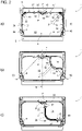
- Both compartment dividers 20 and 40 are in Figure 2a arranged at the second divider position 22 or 42, in which they do not divide the storage volume 4 into a first sub-compartment 12 and a respective further sub-compartment. Rather, the two compartment dividers 20 and 40 rest against the storage wall 6 .
- the compartment divider 20, 40 can be transferred from the second divider position 22, 42 to a third divider position 23, 43 by deflecting the central area 31, 51 about the bending axes 34, 35 or 54, 55, in which the central area 31 , 51 divides the storage volume into a third compartment 19 and a fourth compartment 13 .
- the compartment divider 40 is initially in contact with the storage wall 6, which corresponds to the second divider position 42.
- the central area 51 can be elastically deformed away from the storage wall 6 by means of an operating force B of a user and thus deflected, while the receiving areas 52, 53 remain in contact with the storage wall 6 because the positioning force P continues to act.
- the deflection takes place accordingly about the bending axes 54 and 55 of the compartment divider 40, first into the third divider position 43.
- the result is in Figure 2b shown.
- the compartment divider can then be transferred into the first divider position 41 by means of another operator B of the user, with the positioning force P having to be overcome in order to deflect the receiving areas 52 and 53 .
- the result is in Figure 2c shown.
- the compartment divider 40 can be transferred from the first divider position 41 into the third divider position 43 by deflecting the receiving areas 52, 53 about the bending axes 54, 54.
- this transfer to the third divider position 43 can take place solely by means of the positioning force P without the user having to do anything. This is because the positioning force P counteracts the complete deflection of the receiving areas 52 and 53 about the divider axes of rotation D.
- the receiving areas are pulled or pressed against the storage wall 6 again.
- the central area 51 of the compartment divider 40 initially remains in the third divider position 43 and can then be transferred to the second divider position 42 by an operator B of the user.
- dead axis connecting axis 50 between the divider mounts 46 and 48
- an elastic deformation of the compartment divider 40 is provided.
- the divider receptacles 26 and 28 or 46 and 48 are each formed with a pivot bearing.
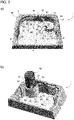
- FIG. 3a and b is the same storage compartment 1, which is essentially similar to the storage compartment of figures 1 and 2 is formed, shown in a schematic oblique view.
- the first compartment divider 20 is shown at the second divider position 22 .
- the arrow here shows the direction of the operator B required to move the compartment divider 20 into the third divider position 23 .
- the second compartment divider 40 is shown at the third divider position 43 .
- the double arrow here shows the possibility, on the one hand, of transferring the compartment divider 40 into the first divider position 41 by means of an operator. On the other hand, starting from there, using the positioning force P, to transfer the compartment divider 40 back into the third divider position 43.
- a small beverage can 100 with a round cross-section is arranged in the second sub-compartment 14 .
- the beverage can 100 is protected against tipping in that the compartment divider 20 is arranged in the third divider position 23 .
- the positioning force P of the positioning devices 25, 27 is applied to the receiving areas 32 and 33 by means of the springs F25 and F27, so that this conveys the macroelastic Press region 31 of compartment divider 20 tightly against a lateral surface of beverage can 100.
- the can 100 is additionally pressed against the receiving wall 6, so that the can 100 is held securely against tipping.
Landscapes
- Engineering & Computer Science (AREA)
- Mechanical Engineering (AREA)
- Physics & Mathematics (AREA)
- Thermal Sciences (AREA)
- Transportation (AREA)
- Vehicle Step Arrangements And Article Storage (AREA)
- Passenger Equipment (AREA)
Description
- Die Erfindung betrifft ein Ablagefach zum Einbau in einem Kraftfahrzeug.
- In Kraftfahrzeugen sind - beispielsweise im Bereich der Mittelkonsole - Ablagefächer angeordnet, die zum Aufbewahren von Stiften, Papieren, Brillen, Telefonen und dergleichen verwendet werden.
- Wegen der Notwendigkeit einer hohen Bauraumausnutzung sind diese Ablagefächer regelmäßig mit einer ausgeprägten Quer- und/oder Längserstreckung ausgebildet, um auch längliche Gegenstände liegend aufnehmen zu können.
- Insbesondere wenn keine separaten Getränkehalter im Kraftfahrzeug vorgesehen sind, werden derartige Ablagefächer von den Fahrzeuginsassen aber auch zum Einstellen von Flaschen, Getränkedosen, Bechern, Gläsern oder dergleichen verwendet. Aufgrund der ausgeprägten Quer- und/oder Längserstreckung der Ablagen ist ein kippsicheres Halten derartiger Getränkebehälter jedoch nicht in jedem Fall sichergestellt.
- Dazu schlägt die
DE 10 2007 006 575 A1 eine Aufnahme zum kippsicheren Halten von Gegenständen mit unterschiedlichen Grundflächendimensionen vor, wobei die Aufnahme eine Bodenfläche und Seitenwände aufweist, welche zusammen ein Aufnahmefach ausbilden. Zum kippsicheren Halten ist ein an einer Seitenwand schwenkbar gelagerter und mit einer Federkraft beaufschlagter Fachteiler vorgesehen, über den die in dem Aufnahmefach abgestellten Gegenstände an wenigstens eine Seitenwand der Aufnahme gedrückt werden. Diese Lösung erfordert allerdings viele Bauteile und ist umständlich zu montieren. - Die
DE 10 2006 018 895 A1 schlägt eine Ablagefach/Becherhalter-Anordnung mit einer gegossenen Basis vor, in die ein Paar elastischer, umkehrbarer Teiler eingesetzt werden kann, die den sicheren Halt unterschiedlich großer Getränkebecher ermöglichen sollen. Die elastischen, umkehrbaren Teiler können eingesetzt und durch eine innere Feder des elastischen Teilers unter Spannung gesetzt werden. Diese Lösung benötigt keine separate Federmechanik. Allerdings ist in den beiden möglichen Stellungen der umkehrbaren Teiler das Ablagefach unterschiedlich - aber dennoch - unterteilt. Eine Ablage größerer Gegenstände in dem Ablagefach wird damit erschwert. - Die
DE102009043768 zeigt ein Ablagefach mit einem Ablagevolumen und einen Fachteiler, der das Ablagevolumen unterteilt. - In Fahrzeugen der Anmelderin und in Fahrzeugen von Wettbewerbern werden mittlerweile Ablagefächer verbaut, die wenigstens einen elastischen Fachteiler aufweisen, der, insbesondere mittels einer Bedienkraft, zwischen einer ersten Teilerposition und einer zweiten Teilerposition überführbar ist. Der Fachteiler unterteilt in der ersten Teilerposition das Ablagevolumen in ein erstes Teilfach und ein zweites Teilfach. So kann mittels des Fachteilers das erste, kleinere Teilfach vom größerem Ablagevolumen abgetrennt werden, sodass beispielsweise ein Getränkebehälter kippsicher in dem ersten Teilfach gehalten werden kann. Wenn der Fachteiler in die zweite Teilerposition überführt ist, bildet der Fachteiler an der zweiten Teilerposition einen Teil der Ablagewandung des Ablagevolumens ausbildet, sodass an der zweiten Teilposition das Ablagevolumen insbesondere zumindest im Wesentlichen ungeteilt ist. So steht zumindest im Wesentlichen das gesamte Ablagevolumen zur Ablage größerer Gegenstände bereit, ohne dass der Fachteiler das zur Verfügung stehende Volumen wesentlich verkleinern würde. Allerdings ist es bei diesen Ablagefächern schwierig für den Nutzer, unterschiedlich große Getränkebehälter kippsicher in dem ersten Teilfach zu halten.
- Vor diesem Hintergrund ist es eine Aufgabe der Erfindung, ein Ablagefach zum Einbau in einem Kraftfahrzeug zu verbessern.
- Diese Aufgabe wird gelöst durch ein Ablagefach mit den Merkmalen von Anspruch 1. Die abhängigen Ansprüche stellen auf vorteilhafte Weiterbildungen der Erfindung ab.
- Gemäß einem Aspekt der Erfindung wird ein Ablagefach zum Einbau in einem Kraftfahrzeug, insbesondere in einer (Mittel-)Konsole eines Kraftfahrzeugs, bereitgestellt.
- Das Ablagefach weist ein Ablagevolumen auf, welches seitlich durch eine wenigstens teilweise umlaufende Ablagewandung begrenzt ist. Insbesondere ist das Ablagevolumen oben (sprich an seiner vertikal oben angeordneten Begrenzung) durch eine Ablageöffnung und ggf. Vorsprünge einer Abdeckung der Konsole begrenzt, wobei die Ablageöffnung beispielsweise durch eine geeignet ausgestaltete Öffnung in einer Abdeckung des Ablagefachs ausgebildet sein kann und/oder durch die (jeweiligen) obere(n) Kante(n) der Ablagewandung. Das Ablagevolumen kann zudem gegebenenfalls unten (sprich an seiner horizontal unten angeordneten Begrenzung) zumindest teilweise durch einen Ablageboden begrenzt sein.
- Zudem weist das Ablagefach wenigstens einen elastischen Fachteiler auf, der zumindest in einem mittigen Bereich einer Längserstreckung des Fachteilers ein makroskopisch elastisches Material aufweist, sodass der Fachteiler zwischen einer ersten Teilerposition und einer zweiten Teilerposition überführbar ist, und der an der ersten Teilerposition das Ablagevolumen in ein erstes Teilfach und ein zweites Teilfach unterteilt, und an der zweiten Teilerposition einen Teil der Ablagewandung des Ablagevolumens ausbildet.
- Darüber hinaus weist das Ablagefach zwei voneinander beabstandete Teileraufnahmen, welche an der Ablagewandung angeordnet sind und an denen jeweils eines von zwei Längsenden des Fachteilers aufgenommen ist, wobei der Fachteiler an jeder der Teileraufnahmen drehbar um eine zu einer Verbindungsachse zwischen den Teileraufnahmen senkrechte Teiler-Drehachse gelagert ist.
- An jeder der Teileraufnahmen ist eine Positioniereinrichtung angeordnet, die dazu eingerichtet ist, den Fachteiler mittels einer Positionierkraft in die zweite Teilerposition zu überführen, insbesondere ausgehend von der ersten Teilerposition oder einer anderen, zwischen der ersten und der zweiten Teilerposition liegenden Teilerposition, und/oder den Fachteiler an der zweiten Teilerposition zu halten.
- Der Erfindung liegt unter anderem die Überlegung zugrunde, mit einer möglichst einfachen Mechanik ein Ablagefach zu gestalten, das sowohl ein möglichst großes maximales Ablagevolumen bereitstellt als auch einen geeigneten Cupholder für verschieden große Getränkebehälter wie beispielsweise einer Dose für einen Energy Drink einerseits (z.B. 250ml) und einer großen Wasserflasche (z.B. 1,5 I) andererseits.
- Die Erfindung basiert nun unter anderem auf der Idee, sich die Eigenschaften eines länglichen, zwischen zwei Führungspunkten eingespannten elastischen Bauteils derart zu Nutze zu machen, dass die Ruhelage einerseits des Totpunktes eine Abteilung eines Cupholders innerhalb des Ablagevolumens ermöglicht, während die Ruhelage andererseits des Totpunktes außerhalb bzw. am Rand des Ablagevolumens angeordnet ist.
- Die zur Überführung des Fachteiler zwischen der ersten Teilerposition der zweiten Teilerposition oder umgekehrt benötigte Bedienkraft kann durch einen Benutzer gemäß einer Ausführung händisch - beispielsweise an einer Bedienlasche - aufgebracht werden. Gemäß einer anderen Ausführung kann auch eine elektromotorische Überführung vorgesehen sein, die dann durch den Benutzer geeignet ausgelöst werden kann.
- Zudem basiert die Erfindung unter anderem auf der Idee, durch eine vorgegebene Positionierkraft hin zu der zweiten Teilerposition die durch den Fachteiler abgetrennte Grundfläche zunächst so weit aufzuspannen, dass der Getränkebehälter eingeführt werden kann. Anschließend wird die Grundfläche durch die vorgegebene Positionierkraft, so weit verkleinert, dass der Fachteiler an der Getränkebehälter anliegt. Mehr noch: durch die vorgegebene Positionierkraft kann gegebenenfalls der Getränkebehälter gegen die Ablagewandung gedrückt und somit kippsicher gehalten werden.
- Um eine möglichst robuste und dabei insbesondere auch preisgünstige und einfache Lösung für die Positioniereinrichtung bereitzustellen, weist gemäß einer Ausführung die Positioniereinrichtung eine Feder auf, die derart vorgespannt ist, dass sie den Fachteiler mittels einer Federkraft in die zweite Teilerposition überführen kann und/oder den Fachteiler an der zweiten Teilerposition halten kann. Insbesondere wirkt die Federkraft also derart, dass ein von der Ablagewandung ausgelenkter Fachteiler mittels der Federkraft wieder zurück an die Ablagewandung gedrückt bzw. gezogen und - einmal dort angekommen - gehalten wird.
- Gemäß einer Ausführung weist der Fachteiler einen mittigen, elastischen Bereich und bezüglich der Längserstreckung des Fachteilers beiderseits seitlich dieses mittigen Bereichs jeweils einen Aufnahmebereich auf. An dem Längsende des jeweiligen Aufnahmebereichs, also insbesondere bezüglich der Längserstreckung des Fachteilers, ist der Fachteiler jeweils in einer der Teileraufnahmen aufgenommen. Gemäß einer Ausführung sind dabei die Aufnahmebereiche makroskopisch starr ausgebildet. Dadurch wird ein "umfassen" bzw. "anschmiegen" des mittigen Bereichs an einen aufgenommenen Getränkebehälter erleichtert - und damit eine Berührfläche zwischen dem Getränkebehälter und dem Fachteiler vergrößert. So kann bei unterschiedlichen Behälterdurchmessern eine bessere Kippsicherung erreicht werden, weil die Positionierkraft wirkt.
- Gemäß einer Ausführung ist zwischen dem mittigen Bereich und jedem der Aufnahmebereiche des Fachteilers jeweils eine Knickachse vorgesehen, die insbesondere parallel zu den Teiler-Drehachsen ausgerichtet ist. Insbesondere kann eine solche Knickachse mittels eines niedrigeren Materialquerschnitts als die umgebenden Bereiche und/oder mittels jeweils eines Drehgelenks ausgebildet sein, welches an der Knickachse angeordnet ist. Damit kann das "umfassen" bzw. "anschmiegen" des mittigen Bereichs an einen aufgenommenen Getränkebehälter zusätzlich erleichtert werden.
- Gemäß einer Ausführung ist durch eine Auslenkung des mittigen Bereichs um die Knickachsen der Fachteiler aus der zweiten Teilerposition in eine dritte Teilerposition überführbar, in welcher der mittige Bereich das Ablagevolumen in ein drittes Teilfach und ein viertes Teilfach unterteilt, wobei insbesondere das dritte Teilfach größer ist als das erste Teilfach und das vierte Teilfach kleiner als das zweite Teilfach. Mit anderen Worten: wenn der Fachteiler zunächst an der Ablagewandung anliegt (entspricht der zweiten Teilerposition), kann der mittige Bereich von der Ablagewandung weg ausgelenkt werden, während die Aufnahmebereiche an der Ablagewandung anliegen bleiben, weil weiterhin die Positionierkraft wirkt. Die Auslenkung erfolgt dementsprechend um die Knickachsen des Fachteilers zunächst in die dritte Teilerposition. Anschließend kann der Fachteiler mittels einer Bedienkraft des Nutzers in die erste Teilerposition überführt werden, wobei zum Auslenken der Aufnahmebereiche die Positionierkraft überwunden werden muss.
- Gemäß einer Ausführung ist in die "andere Richtung" durch eine Auslenkung der Aufnahmebereiche um die Knickachsen der Fachteiler aus der ersten Teilerposition in die dritte Teilerposition überführbar. Denn hier wirkt die Positionierkraft der vollständigen Auslenkung der Aufnahmebereiche um die Teiler-Drehachse entgegen. Die Aufnahmeelemente werden wieder an die Ablagewandung heran gezogen bzw. gedrückt. Der mittige Bereich des Fachteilers verbleibt zunächst in der dritten Teilerposition kann anschließend mittels einer Bedienkraft des Nutzers in die zweite Teilerposition überführt werden.
- Gemäß unterschiedlichen Ausführungen kann der Fachteiler eine größere oder kleinere Vertikalerstreckung (entspricht insbesondere der Erstreckung entlang einer Teiler-Drehachse) aufweisen. So kann der Fachteiler beispielsweise einen, insbesondere horizontal verlaufenden, runden oder ovalen Querschnitt aufweisen. In einem anderen Ausführungsbeispiel kann der Fachteiler die Gestalt einer dünnen Wandung aufweisen.
- Jedenfalls weist der Fachteiler ein makroskopisch elastisches Material auf, insbesondere einen elastischen Polymer- und/oder Metallwerkstoff, der insbesondere dazu geeignet ist, in einem Kraftfahrzeuginnenraum verbaut zu werden.
- Gemäß einer Ausführung resultiert die Elastizität des Fachteilers zumindest im Wesentlichen aus der Verwendung eines makroskopisch elastischen Materials, insbesondere eines Polymerwerkstoffs (z.B. ein geeignetes Elastomer) und/oder eines Metallwerkstoffs (z.B. ein flaches Federstahlband wie bei bekannten, haushaltsüblichen Maßbändern), an zumindest einem Teil der Längserstreckung oder der gesamten Längserstreckung des Fachteilers, sodass auf diese Weise der Fachteiler zwischen der ersten Teilerposition und der zweiten Teilerposition überführt werden kann. Insbesondere ist das elastische Polymer zumindest in einem mittigen Bereich der Längserstreckung des Fachteilers angeordnet.
- Um den zu haltenden Behälter in seiner Position fest und klapperfrei zu halten, sind gemäß einer Ausführung in einem Bereich, in welchem der Fachteiler das makroskopisch elastische Material aufweist, wenigstens ein, insbesondere mehrere, Vorsprünge, insbesondere Noppen und/oder Polster, auf einer dem zu haltenden Behälter zugewandten Seite angeordnet.
- Um den Totpunkt der Überführung des Fachteilers zwischen der ersten Teilerposition und der zweiten Teilerposition zu definieren, sind gemäß einer Ausführung an der Ablagewandung zwei voneinander beabstandete Teileraufnahmen angeordnet, an denen jeweils eines von zwei Längsenden des Fachteilers aufgenommen ist.
- Insbesondere kann durch die Positionierung der Teileraufnahmen auch sichergestellt werden, dass der Fachteiler in der zweiten Teilerposition einen Teil der Ablagewandung ausbildet. Insbesondere können auch die Teileraufnahmen einen Teil der Ablagewandung ausbilden.
- Beispielsweise kann eine Teileraufnahme ein Drehscharnier aufweisen, dessen Drehachse entlang einer Teiler-Drehachse verläuft. Gemäß einer Ausführung ist dazu der Fachteiler an jeder der Teileraufnahmen drehbar um eine zu einer Verbindungsachse zwischen den Teileraufnahmen, insbesondere die Totpunktachse, senkrechte Teiler-Drehachse gelagert.
- Gemäß einer Ausführung verläuft die Teiler-Drehachse zumindest im Wesentlichen parallel zu einer Erstreckungsebene der Ablagewandung, um eine einfache Überführung des Fachteilers zwischen der ersten und der zweiten Teilerposition zu unterstützen.
- Insbesondere, damit runde Getränkebehälter kippsicher gehalten werden können, weist gemäß einer Ausführung der durch den Fachteiler ausgebildete Teil der Ablagewandung eine zumindest im Wesentlichen konstante Krümmung auf, sodass dieser Teil der Ablagewandung einen zumindest im Wesentlichen konstanten Radius aufweist.
- Um die Kippsicherung weiter zu verbessern, sind gemäß einer Ausführung der Fachteiler an der ersten Teilerposition und die Ablagewandung im Bereich des nicht an der zweiten Teilerposition angeordneten Fachteilers zumindest in einem Teilbereich symmetrisch bezüglich einer Verbindungsachse zwischen den Teileraufnahmen angeordnet. Insbesondere beschreibt dabei der symmetrische Teilbereich einen Teilkreis und/oder eine Teilellipse um einen Punkt auf der Verbindungsachse.
- Um verschieden geformte Gegenstände im Ablagefach aufnehmen zu können, insbesondere um beispielsweise runde und eckige Getränkebehälter aufnehmen zu können, weist gemäß einer Ausführung das Ablagefach jenseits des Fachteilers eine prismatische, insbesondere eine rechteckige, Grundform auf und/oder ist der Fachteiler an einer Ecke der Grundform angeordnet.
- Um zumindest zwei Getränkebehälter in dem Ablagefach aufnehmen zu können, sind gemäß einer Ausführung zwei voneinander beabstandete Fachteiler vorgesehen. Insbesondere sind die beiden Fachteiler spiegelbildlich bezüglich einer Mittenlängsachse des Ablagefachs ausgebildet. So eignet sich das Ablagefach beispielsweise zum Einbau in eine Mittelkonsole eines Kraftfahrzeuges, wobei dann beispielsweise einem Fahrersitzplatz unter dem Beifahrersitzplatz jeweils ein Fachteiler zugeordnet sein kann.
- Weitere Vorteile und Anwendungsmöglichkeiten der Erfindung ergeben sich aus der nachfolgenden Beschreibung im Zusammenhang mit den Figuren.
- Fig. 1
- zeigt eine perspektivische Schrägansicht eines Ablagefachs mit zwei Fachteilern nach einer beispielhaften Ausführung der Erfindung in einem ersten Betriebszustand.
- Fig. 2
- zeigt eine Draufsicht des Ablagefachs aus
Fig. 1 in dem ersten Betriebszustand (Fig. 2a ) sowie in einem zweiten Betriebszustand (Fig. 2b ) und in einem dritten Betriebszustand (Fig. 3c). - Fig. 3a
- zeigt eine Schrägansicht eines Ablagefachs mit zwei Fachteilern nach einer weiteren beispielhaften Ausführung der Erfindung in einem ersten Betriebszustand.
- Fig. 3b
- zeigt das Ablagefach aus
Fig. 3a in einem zweiten Betriebszustand. -
Fig. 1 zeigt ein Ablagefach 1, welches in einer Konsole 2 eines ansonsten nicht dargestellten Kraftfahrzeugs verbaut ist. Die Konsole ist im Ausführungsbeispiel eine Mittelkonsole zwischen einem Fahrersitzplatz und einem Beifahrersitzplatz. - Das Ablagefach 1 weist ein Ablagevolumen 4 auf, welches seitlich durch eine Ablagewandung 6 begrenzt ist. Zum restlichen Fahrzeuginnenraum hin (also zumindest im Wesentlichen nach oben hin) ist das Ablagevolumen 4 durch eine Ablageöffnung 8 begrenzt. Die Begrenzung der Ablageöffnung 8 ist im Ausführungsbeispiel in Teilbereichen der Ablagewandung 6 als obere Kante dieser Ablagewandung ausgebildet, in anderen Teilbereichen durch Vorsprünge einer Konsolenabdeckung, welche in eine senkrechte Projektion der Ablagewandung 6 eingreifen.
- Die Ablageöffnung 8 weist dabei eine rechteckige Grundform auf, wobei an den hinteren beiden Ecken des Rechtecks jeweils teilkreisförmige Abrundungen angeordnet sind.
- Im Bereich der teilkreisförmigen Abrundungen weist das Ablagefach 1 zwei elastische Fachteiler 20 und 40 auf, die voneinander spiegelbildlich bezüglich einer Mittenlängsachse M des Ablagefachs 1 bzw. des Ablagevolumens 4 beabstandet sind. Das Ablagefach 1 ist somit symmetrisch bezüglich der Mittenlängsachse M ausgebildet.
- In der Darstellung der
Fig. 1 sind beide Fachteiler 20 und 40 jeweils an einer zweiten Teilerposition 22 bzw. 42 und damit an der Begrenzung des Ablagevolumens 4 angeordnet. Der Fachteiler 20 bildet einen Teil 29 der Ablagewandung 6 aus; der Fachteiler 40 einen Teil 49 (inFig. 1 nicht dargestellt, sieheFig. 2 ) der Ablagewandung 6. - Die Fachteiler 20, 40 weisen jeweils einen mittigen Bereich 31, 51 auf, in welchem der Fachteiler 20, 40 ein makroskopisch elastisches Material aufweist. Bezüglich seiner Längserstreckung weist jeder der Fachteiler 20, 40 beiderseits seitlich des mittigen Bereichs 31, 51 jeweils einen Aufnahmebereich 32 und 33 bzw. 52 und 53 auf. Die Aufnahmebereiche 32, 33, 52, 53 sind im Ausführungsbeispiel makroskopisch starr ausgebildet.
- Das Ablagefach 1 weist für jeden Fachteiler 20, 40 zwei voneinander beabstandete Teileraufnahmen 26 und 28 bzw. 46 und 48, welche an der Ablagewandung 6 angeordnet sind und an denen jeweils eines von zwei Längsenden des Fachteilers 20, 40 aufgenommen ist. Der jeweilige Fachteiler 20 bzw. 40 ist an den zugeordneten Teileraufnahmen 26 und 28 bzw. 46 und 48 drehbar um eine zu einer Verbindungsachse zwischen den Teileraufnahmen senkrechte Teiler-Drehachse D gelagert.
- Wie insbesondere den Details I und II in
Fig. 1 (Detail II zeigt den markierten Abschnitt von hinten, also von der inFig. 1 an sich nicht sichtbaren Seite) zu entnehmen ist, ist an jeder der Teileraufnahmen 26, 28, 46, 48 jeweils eine Positioniereinrichtung 25, 27, 45, 47 angeordnet, die dazu eingerichtet ist, den jeweiligen Fachteiler 20, 40 mittels einer Positionierkraft P in die zweite Teilerposition 22, 42 zu überführen oder in dieser Position zu halten. Im Ausführungsbeispiel weist die Positioniereinrichtung jeweils eine Feder F25, F27, F45, F47 auf, die derart vorgespannt ist, dass sie den Fachteiler 20 bzw. 40 mittels einer Federkraft in die zweite Teilerposition überführen oder ihn dort halten kann. Insbesondere wirkt die Federkraft also derart, dass ein von der Ablagewandung 6 ausgelenkter Fachteiler 20, 40 mittels der zugeordneten Federn F25, F27 bzw. F45, F47 wieder zurück an die Ablagewandung 6 gedrückt bzw. gezogen und dort angekommen gehalten wird. - Zwischen dem mittigen Bereich 31, 51 und jedem der Aufnahmebereiche 32 und 33 bzw. 52 und 53 des Fachteilers 20, 40 ist jeweils eine Knickachse 34, 35 bzw. 54, 55 vorgesehen, die insbesondere parallel zu den Teiler-Drehachsen D ausgerichtet ist. Im Ausführungsbeispiel sind die Knickachsen 34, 35 bzw. 54, 55 jeweils mittels Drehgelenken 36, 37 bzw. 56, 57 ausgebildet, welche an der jeweiligen Knickachse angeordnet sind.
-
Fig. 2 erläutert zu dem Ablagefach 1 derFig. 1 , wie die beiden Fachteiler 20 und 40 zwischen der zweiten Teilerposition 22 bzw. 42 und einer ersten Teilerposition 41 und einer dritten Teilerposition 23 bzw. 43 überführt werden können. - Der Fachteiler 20 ist an zwei Teileraufnahmen 26 und 28 aufgenommen und gelagert, an welchen er jeweils drehbar um eine Längsachse der Teileraufnahmen gelagert ist. Der Fachteiler 40 ist an zwei Teileraufnahmen 46 und 48 aufgenommen und gelagert, an welchen er jeweils drehbar um eine Längsachse der Teileraufnahmen gelagert ist.
- Beide Fachteiler 20 und 40 sind in
Fig. 2a an der zweiten Teilerposition 22 bzw. 42 angeordnet, in welcher sie das Ablagevolumen 4 nicht in ein erstes Teilfach 12 und ein jeweiliges weiteres Teilfachunterteilen. Vielmehr liegen die beiden Fachteiler 20 und 40 an der Ablagewandung 6 an. - Im Ausführungsbeispiel ist durch eine Auslenkung des mittigen Bereichs 31, 51 um die Knickachsen 34, 35 bzw. 54, 55 der Fachteiler 20, 40 aus der zweiten Teilerposition 22, 42 in eine dritte Teilerposition 23, 43 überführbar, in welcher der mittige Bereich 31, 51 das Ablagevolumen in ein drittes Teilfach 19 und ein viertes Teilfach 13 unterteilt.
- Wie in
Fig. 2a dargestellt, liegt also der Fachteiler 40 zunächst an der Ablagewandung 6 an, was der zweiten Teilerposition 42 entspricht. - Davon ausgehend kann der mittige Bereich 51 von der Ablagewandung 6 weg mittels einer Bedienkraft B eines Nutzers elastisch verformt und dadurch ausgelenkt werden, während die Aufnahmebereiche 52, 53 an der Ablagewandung 6 anliegen bleiben, weil weiterhin die Positionierkraft P wirkt. Die Auslenkung erfolgt dementsprechend um die Knickachsen 54 und 55 des Fachteilers 40 zunächst in die dritte Teilerposition 43. Das Ergebnis ist in
Fig. 2b dargestellt. - Anschließend kann der Fachteiler mittels einer weiteren Bedienkraft B des Nutzers in die erste Teilerposition 41 überführt werden, wobei zum Auslenken der Aufnahmebereiche 52 und 53 die Positionierkraft P überwunden werden muss. Das Ergebnis ist in
Fig. 2c dargestellt. - In die "andere Richtung" ist durch eine Auslenkung der Aufnahmebereiche 52, 53 um die Knickachsen 54, 54 der Fachteiler 40 aus der ersten Teilerposition 41 in die dritte Teilerposition 43 überführbar. Beispielsweise kann nach einem Entfernen eines eingestellten Getränkebehälters aus dem zweiten Teilfach 16 diese Überführung in die dritte Teilerposition 43 ohne Zutun des Nutzers allein mittels der Positionierkraft P erfolgen. Denn die Positionierkraft P wirkt der vollständigen Auslenkung der Aufnahmebereiche 52 und 53 um die Teiler-Drehachsen D entgegen. Die Aufnahmebereiche werden wieder an die Ablagewandung 6 heran gezogen bzw. gedrückt. Der mittige Bereich 51 des Fachteilers 40 verbleibt zunächst in der dritten Teilerposition 43 kann anschließend mittels einer Bedienkraft B des Nutzers in die zweite Teilerposition 42 überführt werden.
- Um den Fachteiler 40 in die erste Teilerposition 41 zu überführen, wurde - beispielsweise durch den Beifahrer - eine Kraft B an einer Bedienlasche 58 aufgebracht, um den Fachteiler 40 über den Totpunkt der elastischen Verformung (vergleiche Totachse = Verbindungsachse 50 zwischen den Teileraufnahmen 46 und 48) zu bewegen. Dazu ist eine elastische Verformung des Fachteilers 40 vorgesehen. Nach Erreichen des Totpunktes erfolgt von selbst eine elastische Verformung des Fachteilers 40 hin zu der in
Fig. 2b dargestellten Position. - Analog gilt das auch für den ersten Fachteiler 20, der in den Darstellungen der
Figuren 2a-c allerdings jeweils an der zweiten Teilerposition 22 angeordnet ist. - Die Teileraufnahmen 26 und 28 bzw. 46 und 48 sind jeweils mit einem Drehlager ausgebildet.
- In den
Figuren 3a und b ist jeweils das gleiche Ablagefach 1, das im Wesentlichen ähnlich dem Ablagefach derFiguren 1 und2 ausgebildet ist, in einer schematischen Schrägansicht dargestellt. - In der
Fig. 3a ist der erste Fachteiler 20 an der zweiten Teilerposition 22 dargestellt. Der Pfeil zeigt hier die Richtung der benötigten Bedienkraft B an, um den Fachteiler 20 in die dritte Teilerposition 23 zu überführen. - Der zweite Fachteiler 40 ist an der dritten Teilerposition 43 dargestellt. Der Doppelpfeil zeigt hier die Möglichkeit, einerseits mittels einer Bedienkraft das Fachteiler 40 in die erste Teilerposition 41 zu überführen. Andererseits von dort ausgehend mittels der Positionierungskraft P den Fachteiler 40 wieder zurück in die dritte Teilerposition 43 zu überführen.
- In der
Fig. 3b ist in dem zweiten Teilfach 14 eine kleine Getränkedose 100 mit einem runden Querschnitt angeordnet. Die Getränkedose 100 ist dadurch gegen ein Verkippen geschützt, dass der Fachteiler 20 in der dritten Teilerposition 23 angeordnet ist. Die Positionierkraft P der Positioniereinrichtungen 25, 27 wird mittels der Federn F25 und F27 auf die Aufnahmebereiche 32 und 33 aufgebracht, sodass diese vermittelt über die Drehgelenke 36 und 37 den makroelastischen Bereich 31 des Fachteilers 20 eng an eine Mantelfläche der Getränkedose 100 pressen. Dadurch wird die Dose 100 zusätzlich gegen die Aufnahmewandung 6 gedrückt, sodass die Dose 100 kippsicher gehalten ist. -
- 1
- Ablagefach
- 2
- Konsole
- 4
- Ablagevolumen
- 6
- Ablagewandung
- 8
- Ablageöffnung
- 10
- Ablageboden
- 12
- erstes Teilfach
- 13
- viertes Teilfach
- 14, 16
- zweites Teilfach
- 19
- drittes Teilfach
- 20, 40
- elastische Fachteiler
- 41
- erste Teilerposition
- 22, 42
- zweite Teilerposition
- 23, 43
- dritte Teilerposition
- 29, 49
- Teil der Ablagewandung
- 26, 28, 46, 48
- Teileraufnahmen
- 25, 27, 45, 47
- Positioniereinrichtung, hier Positionierfeder
- 30, 50
- Verbindungsachse
- 31, 51
- mittiger Bereich
- 32, 33, 52, 53
- Aufnahmebereiche
- 34, 35, 54, 55
- Knickachse
- 36, 37, 56, 57
- Drehgelenk
- 38, 58
- Bedienlasche
- 100
- Getränkedose
- D
- Teiler-Drehachse
- B
- Bedienkraft
- M
- Mittenlängsachse des Ablagefachs
- P
- Positionierkraft, hier Federkraft
Claims (13)
- Ablagefach (1) zum Einbau in einem Kraftfahrzeug, aufweisend:- ein Ablagevolumen (4), welches seitlich durch eine wenigstens teilweise umlaufende Ablagewandung (6) begrenzt ist,- wenigstens einen elastischen Fachteiler (20, 40), der zumindest in einem mittigen Bereich (31, 51) einer Längserstreckung des Fachteilers (20, 40) ein makroskopisch elastisches Material aufweist, sodass der Fachteiler zwischen einer ersten Teilerposition (41) und einer zweiten Teilerposition (22, 42) überführbar ist, und der an der ersten Teilerposition das Ablagevolumen in ein erstes Teilfach (12) und ein zweites Teilfach (14, 16) unterteilt und an der zweiten Teilerposition einen Teil (29, 49) der Ablagewandung (6) des Ablagevolumens ausbildet,- zwei voneinander beabstandete Teileraufnahmen (26, 28; 46, 48), welche an der Ablagewandung angeordnet sind und an denen jeweils eines von zwei Längsenden des Fachteilers aufgenommen ist, wobei der Fachteiler an jeder der Teileraufnahmen drehbar um eine zu einer Verbindungsachse (30, 50) zwischen den Teileraufnahmen senkrechte Teiler-Drehachse (D) gelagert ist, dadurch gekennzeichnet, dassan jeder der Teileraufnahmen eine Positioniereinrichtung (25, 27, 45, 47) angeordnet ist, die dazu eingerichtet ist, den Fachteiler mittels einer Positionierkraft (P) in die zweite Teilerposition zu überführen und/oder den Fachteiler an der zweiten Teilerposition zu halten.
- Ablagefach gemäß Anspruch 1, dadurch gekennzeichnet, dass die Positioniereinrichtung eine Feder (F25, F27, F45, F47) aufweist, die derart vorgespannt ist, dass sie den Fachteiler mittels einer Federkraft (P) in die zweite Teilerposition überführen und/oder den Fachteiler an der zweiten Teilerposition halten kann.
- Ablagefach gemäß einem der vorherigen Ansprüche, dadurch gekennzeichnet, dass der Fachteiler beiderseits seitlich des mittigen Bereichs jeweils einen Aufnahmebereich (32, 33, 52, 53) aufweist, an dessen Längsende der Fachteiler jeweils in einer der Teileraufnahmen aufgenommen ist.
- Ablagefach gemäß Anspruch 3, dadurch gekennzeichnet, dass die Aufnahmebereiche makroskopisch starr ausgebildet sind.
- Ablagefach gemäß Anspruch 3 oder 4, dadurch gekennzeichnet, dass zwischen dem mittigen Bereich und jedem der Aufnahmebereiche des Fachteilers jeweils eine Knickachse (34, 35, 54, 55) vorgesehen ist.
- Ablagefach gemäß Anspruch 5, dadurch gekennzeichnet, dass an der Knickachse jeweils ein Drehgelenk (36, 37, 56, 57) angeordnet ist.
- Ablagefach gemäß Anspruch 5 oder 6, dadurch gekennzeichnet, dass durch eine Auslenkung des mittigen Bereichs um die Knickachsen der Fachteiler aus der zweiten Teilerposition in eine dritte Teilerposition (23, 43) überführbar ist, in welcher der mittige Bereich das Ablagevolumen in ein drittes Teilfach (19) und ein viertes Teilfach (13) unterteilt.
- Ablagefach gemäß einem der Ansprüche 5 bis 7, dadurch gekennzeichnet, dass durch eine Auslenkung der Aufnahmebereiche um die Knickachsen der Fachteiler aus der ersten Teilerposition in die dritte Teilerposition überführbar ist.
- Ablagefach gemäß einem der vorhergehenden Ansprüche, dadurch gekennzeichnet, dass der durch den Fachteiler ausgebildete Teil (29, 49) der Ablagewandung eine zumindest im Wesentlichen konstante Krümmung aufweist, sodass dieser Teil der Ablagewandung einen zumindest im Wesentlichen konstanten Radius aufweist.
- Ablagefach gemäß einem der vorhergehenden Ansprüche, dadurch gekennzeichnet, dass das Ablagefach jenseits des Fachteilers eine prismatische, insbesondere eine rechteckige, Grundform aufweist und der Fachteiler an einer Ecke der Grundform angeordnet ist.
- Ablagefach gemäß einem der vorhergehenden Ansprüche, dadurch gekennzeichnet, dass zwei voneinander beabstandete Fachteiler (20, 40) vorgesehen sind.
- Ablagefach gemäß Anspruch 11, dadurch gekennzeichnet, dass die beiden Fachteiler spiegelbildlich bezüglich einer Mittenlängsachse (M) des Ablagefachs ausgebildet sind.
- Ablagefach gemäß einem der vorhergehenden Ansprüche, dadurch gekennzeichnet, dass in einem Bereich, in welchem der Fachteiler (20, 40) das makroskopisch elastische Material aufweist, wenigstens ein Vorsprung auf einer dem zu haltenden Behälter zugewandten Seite angeordnet ist.
Applications Claiming Priority (2)
| Application Number | Priority Date | Filing Date | Title |
|---|---|---|---|
| DE102019106311.6A DE102019106311A1 (de) | 2019-03-12 | 2019-03-12 | Ablagefach mit einem elastischen Fachteiler |
| PCT/EP2020/053039 WO2020182382A1 (de) | 2019-03-12 | 2020-02-06 | Ablagefach mit einem elastischen fachteiler |
Publications (2)
| Publication Number | Publication Date |
|---|---|
| EP3938241A1 EP3938241A1 (de) | 2022-01-19 |
| EP3938241B1 true EP3938241B1 (de) | 2023-01-18 |
Family
ID=69500758
Family Applications (1)
| Application Number | Title | Priority Date | Filing Date |
|---|---|---|---|
| EP20704008.0A Active EP3938241B1 (de) | 2019-03-12 | 2020-02-06 | Ablagefach mit einem elastischen fachteiler |
Country Status (5)
| Country | Link |
|---|---|
| US (1) | US12240368B2 (de) |
| EP (1) | EP3938241B1 (de) |
| CN (1) | CN113557169B (de) |
| DE (1) | DE102019106311A1 (de) |
| WO (1) | WO2020182382A1 (de) |
Families Citing this family (6)
| Publication number | Priority date | Publication date | Assignee | Title |
|---|---|---|---|---|
| US11577655B2 (en) * | 2020-06-03 | 2023-02-14 | John J. Hahn | Flexible shelf guard for recreational vehicles |
| DE102023107920A1 (de) | 2023-03-29 | 2024-10-02 | Dr. Ing. H.C. F. Porsche Aktiengesellschaft | Stauvorrichtung zum sicheren Verstauen von Gegenständen in einem Kraftfahrzeug |
| US12227117B2 (en) * | 2023-03-31 | 2025-02-18 | GM Global Technology Operations LLC | Reconfigurable storage bin for a vehicle |
| USD1049009S1 (en) * | 2023-05-08 | 2024-10-29 | Shenzhen Yinglaifa Technology Co., Ltd. | Car gear shift storage box |
| USD1049003S1 (en) * | 2023-05-15 | 2024-10-29 | Qiulin Cao | Car center console storage box |
| USD1123789S1 (en) * | 2024-06-04 | 2026-04-28 | RSG Innovations LLC | Vehicle cup holder |
Family Cites Families (18)
| Publication number | Priority date | Publication date | Assignee | Title |
|---|---|---|---|---|
| DE19905096A1 (de) | 1999-02-09 | 2000-08-10 | Volkswagen Ag | Vorrichtung zum Verstauen von mitgeführten Gegenständen |
| JP4364988B2 (ja) | 1999-12-15 | 2009-11-18 | 三ツ星化成品株式会社 | カップホルダー |
| DE10253405A1 (de) * | 2001-11-22 | 2003-06-18 | Nifco Inc | Auszugvorrichtung |
| DE10206267A1 (de) * | 2002-02-15 | 2003-08-28 | Fischer Automotive Sys Gmbh | Halter für einen Getränkebehälter |
| US7213793B2 (en) * | 2005-04-24 | 2007-05-08 | Lear Corporation | Invertible storage compartment divider |
| DE102007006575B4 (de) * | 2007-02-09 | 2009-10-29 | Lisa Dräxlmaier GmbH | Cupholder mit gefederter Klappe |
| DE102009000972A1 (de) * | 2009-02-18 | 2010-08-19 | Ford Global Technologies, LLC, Dearborn | Ablagefach für ein Kraftfahrzeug |
| DE102009043771A1 (de) * | 2009-09-30 | 2011-03-31 | GM Global Technology Operations, Inc., Detroit | Aufbewahrungsvorrichtung für Gegenstände in einem Kraftfahrzeug |
| GB2474138B (en) * | 2009-09-30 | 2015-07-22 | Gm Global Tech Operations Inc | Storage device for objects in a motor vehicle |
| DE102009043768A1 (de) * | 2009-09-30 | 2011-03-31 | GM Global Technology Operations, Inc., Detroit | Aufbewahrungsvorrichtung für Gegenstände in einem Kraftfahrzeug |
| CN203460789U (zh) | 2010-06-30 | 2014-03-05 | 佛吉亚内饰系统有限公司 | 板形分隔件及包括分隔件的储存装置 |
| DE102010025624A1 (de) * | 2010-06-30 | 2012-01-05 | Faurecia Innenraum Systeme Gmbh | Plattenförmiger Raumteiler und Ablagevorrichtung mit einem Raumteiler |
| US8485581B2 (en) * | 2010-10-14 | 2013-07-16 | GM Global Technology Operations LLC | Active material based holding fixtures |
| US8517444B2 (en) * | 2012-01-20 | 2013-08-27 | Faurecia Interior Systems, Inc. | Reconfigurable console assembly and method of assembling the same |
| DE102012020976A1 (de) * | 2012-10-25 | 2014-04-30 | Volkswagen Aktiengesellschaft | Staufachanordnung für ein Fahrzeug |
| DE102013212551B4 (de) * | 2013-06-28 | 2017-01-12 | Bos Gmbh & Co. Kg | Aufnahmevorrichtung für wenigstens ein Behältnis in einem Fahrzeuginnenraum |
| DE102014016230B4 (de) * | 2014-10-27 | 2019-11-14 | Audi Ag | Ablagefach eines Fahrzeugs |
| US9616817B2 (en) * | 2015-05-05 | 2017-04-11 | GM Global Technology Operations LLC | Silicone storage assembly for a vehicle |
-
2019
- 2019-03-12 DE DE102019106311.6A patent/DE102019106311A1/de active Pending
-
2020
- 2020-02-06 CN CN202080019556.9A patent/CN113557169B/zh active Active
- 2020-02-06 US US17/436,924 patent/US12240368B2/en active Active
- 2020-02-06 EP EP20704008.0A patent/EP3938241B1/de active Active
- 2020-02-06 WO PCT/EP2020/053039 patent/WO2020182382A1/de not_active Ceased
Also Published As
| Publication number | Publication date |
|---|---|
| CN113557169A (zh) | 2021-10-26 |
| DE102019106311A1 (de) | 2020-09-17 |
| US12240368B2 (en) | 2025-03-04 |
| CN113557169B (zh) | 2023-05-26 |
| EP3938241A1 (de) | 2022-01-19 |
| WO2020182382A1 (de) | 2020-09-17 |
| US20220153178A1 (en) | 2022-05-19 |
Similar Documents
| Publication | Publication Date | Title |
|---|---|---|
| EP3938241B1 (de) | Ablagefach mit einem elastischen fachteiler | |
| EP0667258B1 (de) | Vorrichtung zum Halten von Getränkebehältern, Trinkgefässen oder dgl. | |
| DE102006018895B4 (de) | Umkehrbarer Ablagefachteiler | |
| EP1277613B1 (de) | Halter für einen Getränkebehälter | |
| DE102007061898A1 (de) | Ablagefach | |
| DE102014220595B4 (de) | Aufnahmevorrichtung für wenigstens ein Speisen- oder Getränkebehältnis in einem Kraftfahrzeug | |
| DE19853671A1 (de) | Behälterhalter für ein Kraftfahrzeug | |
| EP3616998A1 (de) | Ablagefach für einen innenraum eines fahrzeugs | |
| DE10112649A1 (de) | In ein Kraftfahrzeug einbaubarer Becherhalter | |
| DE102007006575B4 (de) | Cupholder mit gefederter Klappe | |
| EP2435273A1 (de) | Haltevorrichtung, insbesondere für getränkebehälter | |
| DE102007061042A1 (de) | Halter für einen Getränkebehälter | |
| DE102004011306A1 (de) | Ablagefach für ein Kraftfahrzeug | |
| DE102023126435A1 (de) | Hilfsaufbewahrungskasten | |
| DE102014016230B4 (de) | Ablagefach eines Fahrzeugs | |
| DE102007032205A1 (de) | Ablagefach und Halter für einen Getränkebehälter | |
| DE102009030576B4 (de) | Einrichtung zum seitlichen Positionieren eines Gegenstandes in einem Behältnis | |
| DE102018126073A1 (de) | Ablagefach mit einem elastischen Fachteiler | |
| DE20308296U1 (de) | Ablagefach | |
| DE102008062278A1 (de) | Halter für Gegenstände | |
| DE10245740B4 (de) | Haltevorrichtung für Getränkebehälter im Staufach eines Fahrzeugs | |
| DE102021110665A1 (de) | Verstaufach mit einer Einstellöffnung, über die ein Getränkebehälter in einen Verstauraum des Verstaufachs einstellbar ist, Konsole für ein Fahrzeug, Fahrzeug | |
| DE102023108542B4 (de) | Fahrzeugkomponente für ein Kraftfahrzeug, aufweisend einen Grundkörper und eine seitlich hieran ausgebildete Verstautasche, und Kraftfahrzeug, umfassend eine Fahrzeugkomponente mit einer Verstautasche | |
| EP4574565A1 (de) | Abstellanlage für ein kraftfahrzeug | |
| DE102010048095A1 (de) | Getränkehaltermodul für wenigstens einen Getränkebehälter |
Legal Events
| Date | Code | Title | Description |
|---|---|---|---|
| STAA | Information on the status of an ep patent application or granted ep patent |
Free format text: STATUS: UNKNOWN |
|
| STAA | Information on the status of an ep patent application or granted ep patent |
Free format text: STATUS: THE INTERNATIONAL PUBLICATION HAS BEEN MADE |
|
| PUAI | Public reference made under article 153(3) epc to a published international application that has entered the european phase |
Free format text: ORIGINAL CODE: 0009012 |
|
| STAA | Information on the status of an ep patent application or granted ep patent |
Free format text: STATUS: REQUEST FOR EXAMINATION WAS MADE |
|
| 17P | Request for examination filed |
Effective date: 20210930 |
|
| AK | Designated contracting states |
Kind code of ref document: A1 Designated state(s): AL AT BE BG CH CY CZ DE DK EE ES FI FR GB GR HR HU IE IS IT LI LT LU LV MC MK MT NL NO PL PT RO RS SE SI SK SM TR |
|
| DAV | Request for validation of the european patent (deleted) | ||
| DAX | Request for extension of the european patent (deleted) | ||
| GRAP | Despatch of communication of intention to grant a patent |
Free format text: ORIGINAL CODE: EPIDOSNIGR1 |
|
| STAA | Information on the status of an ep patent application or granted ep patent |
Free format text: STATUS: GRANT OF PATENT IS INTENDED |
|
| INTG | Intention to grant announced |
Effective date: 20221005 |
|
| GRAS | Grant fee paid |
Free format text: ORIGINAL CODE: EPIDOSNIGR3 |
|
| GRAA | (expected) grant |
Free format text: ORIGINAL CODE: 0009210 |
|
| STAA | Information on the status of an ep patent application or granted ep patent |
Free format text: STATUS: THE PATENT HAS BEEN GRANTED |
|
| AK | Designated contracting states |
Kind code of ref document: B1 Designated state(s): AL AT BE BG CH CY CZ DE DK EE ES FI FR GB GR HR HU IE IS IT LI LT LU LV MC MK MT NL NO PL PT RO RS SE SI SK SM TR |
|
| REG | Reference to a national code |
Ref country code: GB Ref legal event code: FG4D Free format text: NOT ENGLISH |
|
| REG | Reference to a national code |
Ref country code: CH Ref legal event code: EP |
|
| REG | Reference to a national code |
Ref country code: DE Ref legal event code: R096 Ref document number: 502020002394 Country of ref document: DE |
|
| REG | Reference to a national code |
Ref country code: AT Ref legal event code: REF Ref document number: 1544502 Country of ref document: AT Kind code of ref document: T Effective date: 20230215 Ref country code: IE Ref legal event code: FG4D Free format text: LANGUAGE OF EP DOCUMENT: GERMAN |
|
| REG | Reference to a national code |
Ref country code: LT Ref legal event code: MG9D |
|
| REG | Reference to a national code |
Ref country code: NL Ref legal event code: MP Effective date: 20230118 |
|
| P01 | Opt-out of the competence of the unified patent court (upc) registered |
Effective date: 20230503 |
|
| PG25 | Lapsed in a contracting state [announced via postgrant information from national office to epo] |
Ref country code: NL Free format text: LAPSE BECAUSE OF FAILURE TO SUBMIT A TRANSLATION OF THE DESCRIPTION OR TO PAY THE FEE WITHIN THE PRESCRIBED TIME-LIMIT Effective date: 20230118 |
|
| PG25 | Lapsed in a contracting state [announced via postgrant information from national office to epo] |
Ref country code: RS Free format text: LAPSE BECAUSE OF FAILURE TO SUBMIT A TRANSLATION OF THE DESCRIPTION OR TO PAY THE FEE WITHIN THE PRESCRIBED TIME-LIMIT Effective date: 20230118 Ref country code: PT Free format text: LAPSE BECAUSE OF FAILURE TO SUBMIT A TRANSLATION OF THE DESCRIPTION OR TO PAY THE FEE WITHIN THE PRESCRIBED TIME-LIMIT Effective date: 20230518 Ref country code: NO Free format text: LAPSE BECAUSE OF FAILURE TO SUBMIT A TRANSLATION OF THE DESCRIPTION OR TO PAY THE FEE WITHIN THE PRESCRIBED TIME-LIMIT Effective date: 20230418 Ref country code: LV Free format text: LAPSE BECAUSE OF FAILURE TO SUBMIT A TRANSLATION OF THE DESCRIPTION OR TO PAY THE FEE WITHIN THE PRESCRIBED TIME-LIMIT Effective date: 20230118 Ref country code: LT Free format text: LAPSE BECAUSE OF FAILURE TO SUBMIT A TRANSLATION OF THE DESCRIPTION OR TO PAY THE FEE WITHIN THE PRESCRIBED TIME-LIMIT Effective date: 20230118 Ref country code: HR Free format text: LAPSE BECAUSE OF FAILURE TO SUBMIT A TRANSLATION OF THE DESCRIPTION OR TO PAY THE FEE WITHIN THE PRESCRIBED TIME-LIMIT Effective date: 20230118 Ref country code: ES Free format text: LAPSE BECAUSE OF FAILURE TO SUBMIT A TRANSLATION OF THE DESCRIPTION OR TO PAY THE FEE WITHIN THE PRESCRIBED TIME-LIMIT Effective date: 20230118 |
|
| PG25 | Lapsed in a contracting state [announced via postgrant information from national office to epo] |
Ref country code: SE Free format text: LAPSE BECAUSE OF FAILURE TO SUBMIT A TRANSLATION OF THE DESCRIPTION OR TO PAY THE FEE WITHIN THE PRESCRIBED TIME-LIMIT Effective date: 20230118 Ref country code: PL Free format text: LAPSE BECAUSE OF FAILURE TO SUBMIT A TRANSLATION OF THE DESCRIPTION OR TO PAY THE FEE WITHIN THE PRESCRIBED TIME-LIMIT Effective date: 20230118 Ref country code: IS Free format text: LAPSE BECAUSE OF FAILURE TO SUBMIT A TRANSLATION OF THE DESCRIPTION OR TO PAY THE FEE WITHIN THE PRESCRIBED TIME-LIMIT Effective date: 20230518 Ref country code: GR Free format text: LAPSE BECAUSE OF FAILURE TO SUBMIT A TRANSLATION OF THE DESCRIPTION OR TO PAY THE FEE WITHIN THE PRESCRIBED TIME-LIMIT Effective date: 20230419 Ref country code: FI Free format text: LAPSE BECAUSE OF FAILURE TO SUBMIT A TRANSLATION OF THE DESCRIPTION OR TO PAY THE FEE WITHIN THE PRESCRIBED TIME-LIMIT Effective date: 20230118 |
|
| REG | Reference to a national code |
Ref country code: CH Ref legal event code: PL |
|
| REG | Reference to a national code |
Ref country code: DE Ref legal event code: R097 Ref document number: 502020002394 Country of ref document: DE Ref country code: BE Ref legal event code: MM Effective date: 20230228 |
|
| PG25 | Lapsed in a contracting state [announced via postgrant information from national office to epo] |
Ref country code: SM Free format text: LAPSE BECAUSE OF FAILURE TO SUBMIT A TRANSLATION OF THE DESCRIPTION OR TO PAY THE FEE WITHIN THE PRESCRIBED TIME-LIMIT Effective date: 20230118 Ref country code: RO Free format text: LAPSE BECAUSE OF FAILURE TO SUBMIT A TRANSLATION OF THE DESCRIPTION OR TO PAY THE FEE WITHIN THE PRESCRIBED TIME-LIMIT Effective date: 20230118 Ref country code: MC Free format text: LAPSE BECAUSE OF FAILURE TO SUBMIT A TRANSLATION OF THE DESCRIPTION OR TO PAY THE FEE WITHIN THE PRESCRIBED TIME-LIMIT Effective date: 20230118 Ref country code: LU Free format text: LAPSE BECAUSE OF NON-PAYMENT OF DUE FEES Effective date: 20230206 Ref country code: LI Free format text: LAPSE BECAUSE OF NON-PAYMENT OF DUE FEES Effective date: 20230228 Ref country code: EE Free format text: LAPSE BECAUSE OF FAILURE TO SUBMIT A TRANSLATION OF THE DESCRIPTION OR TO PAY THE FEE WITHIN THE PRESCRIBED TIME-LIMIT Effective date: 20230118 Ref country code: DK Free format text: LAPSE BECAUSE OF FAILURE TO SUBMIT A TRANSLATION OF THE DESCRIPTION OR TO PAY THE FEE WITHIN THE PRESCRIBED TIME-LIMIT Effective date: 20230118 Ref country code: CZ Free format text: LAPSE BECAUSE OF FAILURE TO SUBMIT A TRANSLATION OF THE DESCRIPTION OR TO PAY THE FEE WITHIN THE PRESCRIBED TIME-LIMIT Effective date: 20230118 Ref country code: CH Free format text: LAPSE BECAUSE OF NON-PAYMENT OF DUE FEES Effective date: 20230228 |
|
| PLBE | No opposition filed within time limit |
Free format text: ORIGINAL CODE: 0009261 |
|
| STAA | Information on the status of an ep patent application or granted ep patent |
Free format text: STATUS: NO OPPOSITION FILED WITHIN TIME LIMIT |
|
| PG25 | Lapsed in a contracting state [announced via postgrant information from national office to epo] |
Ref country code: SK Free format text: LAPSE BECAUSE OF FAILURE TO SUBMIT A TRANSLATION OF THE DESCRIPTION OR TO PAY THE FEE WITHIN THE PRESCRIBED TIME-LIMIT Effective date: 20230118 |
|
| REG | Reference to a national code |
Ref country code: IE Ref legal event code: MM4A |
|
| 26N | No opposition filed |
Effective date: 20231019 |
|
| PG25 | Lapsed in a contracting state [announced via postgrant information from national office to epo] |
Ref country code: SI Free format text: LAPSE BECAUSE OF FAILURE TO SUBMIT A TRANSLATION OF THE DESCRIPTION OR TO PAY THE FEE WITHIN THE PRESCRIBED TIME-LIMIT Effective date: 20230118 Ref country code: IE Free format text: LAPSE BECAUSE OF NON-PAYMENT OF DUE FEES Effective date: 20230206 |
|
| PG25 | Lapsed in a contracting state [announced via postgrant information from national office to epo] |
Ref country code: BE Free format text: LAPSE BECAUSE OF NON-PAYMENT OF DUE FEES Effective date: 20230228 |
|
| PG25 | Lapsed in a contracting state [announced via postgrant information from national office to epo] |
Ref country code: IT Free format text: LAPSE BECAUSE OF FAILURE TO SUBMIT A TRANSLATION OF THE DESCRIPTION OR TO PAY THE FEE WITHIN THE PRESCRIBED TIME-LIMIT Effective date: 20230118 |
|
| PG25 | Lapsed in a contracting state [announced via postgrant information from national office to epo] |
Ref country code: BG Free format text: LAPSE BECAUSE OF FAILURE TO SUBMIT A TRANSLATION OF THE DESCRIPTION OR TO PAY THE FEE WITHIN THE PRESCRIBED TIME-LIMIT Effective date: 20230118 |
|
| PG25 | Lapsed in a contracting state [announced via postgrant information from national office to epo] |
Ref country code: BG Free format text: LAPSE BECAUSE OF FAILURE TO SUBMIT A TRANSLATION OF THE DESCRIPTION OR TO PAY THE FEE WITHIN THE PRESCRIBED TIME-LIMIT Effective date: 20230118 |
|
| PGFP | Annual fee paid to national office [announced via postgrant information from national office to epo] |
Ref country code: AT Payment date: 20250417 Year of fee payment: 5 |
|
| PG25 | Lapsed in a contracting state [announced via postgrant information from national office to epo] |
Ref country code: CY Free format text: LAPSE BECAUSE OF FAILURE TO SUBMIT A TRANSLATION OF THE DESCRIPTION OR TO PAY THE FEE WITHIN THE PRESCRIBED TIME-LIMIT; INVALID AB INITIO Effective date: 20200206 |
|
| PG25 | Lapsed in a contracting state [announced via postgrant information from national office to epo] |
Ref country code: HU Free format text: LAPSE BECAUSE OF FAILURE TO SUBMIT A TRANSLATION OF THE DESCRIPTION OR TO PAY THE FEE WITHIN THE PRESCRIBED TIME-LIMIT; INVALID AB INITIO Effective date: 20200206 |
|
| PG25 | Lapsed in a contracting state [announced via postgrant information from national office to epo] |
Ref country code: TR Free format text: LAPSE BECAUSE OF FAILURE TO SUBMIT A TRANSLATION OF THE DESCRIPTION OR TO PAY THE FEE WITHIN THE PRESCRIBED TIME-LIMIT Effective date: 20230118 |
|
| PGFP | Annual fee paid to national office [announced via postgrant information from national office to epo] |
Ref country code: GB Payment date: 20260219 Year of fee payment: 7 |
|
| PGFP | Annual fee paid to national office [announced via postgrant information from national office to epo] |
Ref country code: DE Payment date: 20260210 Year of fee payment: 7 |
|
| PG25 | Lapsed in a contracting state [announced via postgrant information from national office to epo] |
Ref country code: AT Free format text: LAPSE BECAUSE OF NON-PAYMENT OF DUE FEES Effective date: 20250206 |
|
| REG | Reference to a national code |
Ref country code: AT Ref legal event code: MM01 Ref document number: 1544502 Country of ref document: AT Kind code of ref document: T Effective date: 20250206 |
|
| PGFP | Annual fee paid to national office [announced via postgrant information from national office to epo] |
Ref country code: FR Payment date: 20260219 Year of fee payment: 7 |