EP3937643B1 - Bearbeitungsanlage für schlachttierteilen, und kupplung für die anlage - Google Patents
Bearbeitungsanlage für schlachttierteilen, und kupplung für die anlage Download PDFInfo
- Publication number
- EP3937643B1 EP3937643B1 EP20711148.5A EP20711148A EP3937643B1 EP 3937643 B1 EP3937643 B1 EP 3937643B1 EP 20711148 A EP20711148 A EP 20711148A EP 3937643 B1 EP3937643 B1 EP 3937643B1
- Authority
- EP
- European Patent Office
- Prior art keywords
- structural part
- edges
- rotation
- lower body
- plant
- Prior art date
- Legal status (The legal status is an assumption and is not a legal conclusion. Google has not performed a legal analysis and makes no representation as to the accuracy of the status listed.)
- Active
Links
Images


Classifications
-
- A—HUMAN NECESSITIES
- A22—BUTCHERING; MEAT TREATMENT; PROCESSING POULTRY OR FISH
- A22B—SLAUGHTERING
- A22B7/00—Slaughterhouse arrangements
- A22B7/001—Conveying arrangements
- A22B7/003—Positioning, orienting or supporting carcasses as they are being conveyed
-
- A—HUMAN NECESSITIES
- A22—BUTCHERING; MEAT TREATMENT; PROCESSING POULTRY OR FISH
- A22C—PROCESSING MEAT, POULTRY, OR FISH
- A22C17/00—Other devices for processing meat or bones
- A22C17/02—Apparatus for holding meat or bones while cutting
-
- A—HUMAN NECESSITIES
- A22—BUTCHERING; MEAT TREATMENT; PROCESSING POULTRY OR FISH
- A22B—SLAUGHTERING
- A22B7/00—Slaughterhouse arrangements
- A22B7/001—Conveying arrangements
- A22B7/002—Devices for hanging animal carcasses while being conveyed or stored, e.g. gambrels, hooks
-
- A—HUMAN NECESSITIES
- A22—BUTCHERING; MEAT TREATMENT; PROCESSING POULTRY OR FISH
- A22C—PROCESSING MEAT, POULTRY, OR FISH
- A22C18/00—Plants, factories, or the like for processing meat
-
- B—PERFORMING OPERATIONS; TRANSPORTING
- B65—CONVEYING; PACKING; STORING; HANDLING THIN OR FILAMENTARY MATERIAL
- B65G—TRANSPORT OR STORAGE DEVICES, e.g. CONVEYORS FOR LOADING OR TIPPING, SHOP CONVEYOR SYSTEMS OR PNEUMATIC TUBE CONVEYORS
- B65G17/00—Conveyors having an endless traction element, e.g. a chain, transmitting movement to a continuous or substantially-continuous load-carrying surface or to a series of individual load-carriers; Endless-chain conveyors in which the chains form the load-carrying surface
- B65G17/20—Conveyors having an endless traction element, e.g. a chain, transmitting movement to a continuous or substantially-continuous load-carrying surface or to a series of individual load-carriers; Endless-chain conveyors in which the chains form the load-carrying surface comprising load-carriers suspended from overhead traction chains
-
- B—PERFORMING OPERATIONS; TRANSPORTING
- B65—CONVEYING; PACKING; STORING; HANDLING THIN OR FILAMENTARY MATERIAL
- B65G—TRANSPORT OR STORAGE DEVICES, e.g. CONVEYORS FOR LOADING OR TIPPING, SHOP CONVEYOR SYSTEMS OR PNEUMATIC TUBE CONVEYORS
- B65G47/00—Article or material-handling devices associated with conveyors; Methods employing such devices
- B65G47/22—Devices influencing the relative position or the attitude of articles during transit by conveyors
- B65G47/24—Devices influencing the relative position or the attitude of articles during transit by conveyors orientating the articles
- B65G47/244—Devices influencing the relative position or the attitude of articles during transit by conveyors orientating the articles by turning them about an axis substantially perpendicular to the conveying plane
-
- B—PERFORMING OPERATIONS; TRANSPORTING
- B65—CONVEYING; PACKING; STORING; HANDLING THIN OR FILAMENTARY MATERIAL
- B65G—TRANSPORT OR STORAGE DEVICES, e.g. CONVEYORS FOR LOADING OR TIPPING, SHOP CONVEYOR SYSTEMS OR PNEUMATIC TUBE CONVEYORS
- B65G2201/00—Indexing codes relating to handling devices, e.g. conveyors, characterised by the type of product or load being conveyed or handled
- B65G2201/02—Articles
- B65G2201/0202—Agricultural and processed food products
Definitions
- the present invention relates to a pig part processing plant.
- EP 1 658 774 discloses a plant as defined generally in the introductory portion of claim 1 herein. This plant has several limitations; among others the known plant requires a person to shift between different positions for processing the sides and the front, respectively, of the pig part passing through a processing station.
- EP 2 512 254 discloses a system for the processing and conveying of individual parts of slaughtered pigs, notably leg parts, hams, and shoulder parts of pigs.
- EP 1191852 discloses a slaughtered animal processing plant with a gear for rotating a lower part of a coupling.
- the object of the present invention is inter alia to provide an improved pig part processing plant wherein in a simple manner the pig parts may be correctly oriented by rotation about a vertical axis for processing.
- a plant according to claim 1 is provided with pig part retaining clamp structures being connected to the conveyor so as to allow for a rotation of the clamp structures about a vertical axis, the processing plant including elongated guiding elements extending in the machine direction and engaging the clamp structures (or couplings connecting the clamp structures to the conveyor) as they are advanced in the machine direction, for bringing about a rotation about a vertical axis.
- the processing plant including elongated guiding elements extending in the machine direction and engaging the clamp structures (or couplings connecting the clamp structures to the conveyor) as they are advanced in the machine direction, for bringing about a rotation about a vertical axis.
- a coupling comprising an upper structural part configured for connection with an overhead conveyor and a lower structural part with a clamp structure for a slaughtered pig part, is also defined in claim 8.
- a processing plant of the present invention may be defined eg. by the combination of slaughtered pig part processing stations of an existing processing plant with a replacement conveyor with guiding elements as defined herein, or by using guiding elements as defined herein in an existing processing plant with a conveyor and slaughtered pig part processing stations.
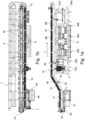
- Fig. 1a generally shows a side view of an embodiment of a slaughtered pig part processing plant 1 including an elongated frame 5 carrying a conveyor 10 that supports and advances a plurality of spaced apart pig part retaining assemblies referred to herein as clamp structures 20 or, for convenience, simply as “clamps”.
- Each clamp 20 is configured for holding a pig part, and the pig parts are advanced by the conveyor 10 in a general machine direction T from a first station 40, where a portion of the pig part is introduced automatically or manually between two jaws of the clamps 20, to a last station 600 where the bone of the processed pig part is removed automatically from the clamps 20.
- the pig part is normally a leg or shoulder part, such the hind shank with the hind foot or the fore shank, see fig. 7 .
- the conveyor 10 of the plant 1 has a first section 11 extending at a relatively low level, and a second section 12 extending upwards to an overhead third section 13 next to which are the plurality of processing stations 100, 200, 300, 400, 500 as well as the last station 600.
- the conveyor 10 runs continuously, with pig parts 2 moving slowly past the processing stations as they are being processed.
- the conveyor 10 has a return part 16 returning the empty clamps 20 from the last station 600 to the first station 40 and extending between redirecting sections 14, 15.
- the conveyor 10 is an endless structure, such as a chain, carrying the clamps 20 via couplings 30 and driven and guided by any conventional means, such as by rollers located at the redirecting sections 14, 15.
- two independently operating processing plants 1 as described above may have their conveyors 10 positioned back to back and be operating with a respective one of the different types of clamps 20 described below, one plant 1 processing hind shanks and the other plant 1 processing fore shanks.
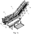
- Fig. 1c is a perspective view of the first station 40, showing also a suspended pig part 2 being advanced from the first station 40 along the second conveyor section 12, held between the jaws of a clamp 20.
- clamps 20, a coupling 30 for coupling each clamp 20 to the conveyor 10, the first station 40, means for rotating the clamps 20 relative to the conveyor frame 5 about a generally vertical axis, and the last station 600 will be discussed.
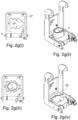
- Figs. 2a-2d show a first embodiment of a clamp 10 of the present invention, which clamp 10 may find use in the plant of fig. 1a or in any other slaughtered pig part processing plant of the general type that includes a conveyor frame with a conveyor for supporting a plurality of spaced apart pig part retaining assemblies and where the conveyor advances the pig parts in a machine direction from one station for introducing pig parts into the retaining assemblies, to a last station where the bones of the processed pig parts leave the retaining assemblies.
- the clamps 20 of the invention are normally of a food compatible material, such as stainless steel or a synthetic material, and generally includes a connecting structure or carrier part 21 carrying two jaws 25, at least one being pivotable.
- the jaws 25 each have an elongated gripping edge 27 that preferably is serrated as shown, or sharpened, as well as a first face 29 and an opposite second face 29'.
- the jaws 25 are mounted to the carrier part 21 with their gripping edges 27 facing one another.
- the two jaws 25 are each mounted for turning relative to the carrier part 21 about a respective axis A, from the shown first position resting against an abutment 21', in which first position the width w of a gap G1 between the opposite gripping edges 27 is relatively small, to second positions where gap G1 is opened up and the aforementioned width w becomes progressively larger.
- the maximum turning of the jaws 25 away from the first position is preferably limited by respective abutments 21".
- the general contour of the gap G1 when viewed from above as in fig. 2c , is oval; generally, the shape of the edges 27 is designed such that the contour of the gap G1 follows the cross-sectional periphery or outline of the inserted portion 3 of the pig part 2, see figs. 2f , 2g(ii) and 2h(ii), with teeth 27' arranged along the edges 27 biting into the pig part as explained below.
- the jaws 25 are normally formed from flat metallic plates and the jaw 25 edges 27 may be defined by replaceable parts.
- the carrier part 21 defines a rear plate and has two outwardly projecting pins 22 onto each of which a tubular structure 26, preferably open only at one end 26', connected to the jaws 25 opposite the gripping edge 27 thereof, is mounted.
- the spring 28, preferably being a wire wound around the respective pin 22 inside the tubular structure 26, is connected with the pin 22 or the rear plate 21 and with the jaw 25, to provide the aforementioned biasing force.
- Two opposite, upright flanges 23 are generally mounted to the carrier part 21 and preferably have apertures 23" for variable positioning of a back-stop plate 24 for the reason explained below, as well as a respective aperture 23' or other structure for connecting the clamp 20 to a respective coupling 30.
- This connection is such as to allow the clamp 20 to be turned about a first axis C relative to the coupling 30 from a position wherein the first faces 29 are oriented more or less downwards as in fig. 4d , to a position wherein the first faces 29 extend generally vertically, as will be the case at the first station 40, cf. figs. 4a-b , where the jaws 25 are in their first position, the clamp 20 being ready to receive a portion of a pig part 2 through applying a generally horizontal force in direction B against the faces 29.
- Fig. 2e shows a second embodiment of the aforementioned clamp 20 of the invention, of generally larger size than the one of figs. 2a-2d , for holding on to a relatively thicker pig part 2, such as portion 3 of a pig fore shank from which the foot has been previously removed, see fig. 2f .
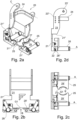
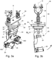
- figs. 3a and 3b an embodiment of a coupling 30 connecting the clamps 20 of the invention to the conveyor 10 will be discussed in further details; figs. 3a and 3b show the coupling 30 used in connection with the first embodiment of the clamps 20 but it may generally used with any of the clamp 20 embodiments disclosed herein.
- Figs. 3a and 3b are perspective and side views, respectively, of the clamp 20 pivotally mounted to a coupling 30 to allow for a rotation of the clamp 20 about the first axis C relative to the coupling 30.
- this may be by a pin 31 attached to a lower structural part 32 of the coupling 30 and received by the aperture 23' of the flange 23 of the clamp 20.
- the clamp 20 may turn by an angle, such as 90° in the direction indicated by the arrow in fig. 3b , to an orientation where the lower faces 29 are oriented generally vertically, for introducing a pig part 2 into the clamp 20 at the first station 40 in the manner described later below.
- the lower structural part 32 on its side is rotatably mounted to an upper structural part 36 of the coupling 30 so as to allow for a turning of the lower structural part 32 relative to the upper structural part 36 about a second axis D which when processing the pig parts 2 is normally vertical and which is generally perpendicular to the first axis C.
- a pin 33 which is received by the upper structural part 36.
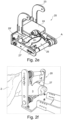
- the upper structural part 36 on its side comprises a plate-like body 37 receiving the pin 33 in a manner allowing mutual rotation and having a number of sockets 38 to each of which is connected a bracket 39 engaging with the conveyor 10, which may be a chain. Relative turning about a generally horizontal axis between the bracket 39 and the sockets 38 may be provided for.
- first axis C and the second axis D normally extend generally horizontally and vertically, respectively, when the clamps 20 move in the machine direction T shown in fig. 1a along the first section 11 and the third section 13 thereof.
- the lower structural part 32 includes a lower body 35 immovably fixed to, or integral with, an upper body 34, which lower body 35 has a number of edges 35', referred to in the following as "second edges", that preferably are straight as shown.
- the lower body 35 also has a downward extension including the pin 31 extending through aperture 23' for connecting the lower structural part 32 with the clamp 20.
- the downward extension includes a circular stem portion S located above the latter pin 31.
- the upper body 34 of the lower structural part 32 also has a number of edges 34', referred to in the following as "first edges", that preferably are straight and that correspond in number to the number of the second edges 35'.
- the second edges 35' are arranged at an angular offset ⁇ relative to the first edges 34' when viewed from above, see sectional views of figs. 5j-l .
- the edges 34', 35' thereof meet at rounded or sharp corners 99, with the upper and lower body 34, 35 having the same contour and showing a rotational symmetry.
- the contour of the upper and lower bodies 34, 35 is generally that of an n-sided regular polygon, such as of an equilateral triangle, a square as in the embodiment of fig. 3a-b , or a regular pentagon, the angular offset ⁇ being 60°, 45° or 36°, respectively, see also fig. 5j-l .
- the plant 1 is preferably configured to provide for a turning of the clamps 20 about the vertical axis D as the clamps 20 move past the processing stations 100, 200, 300, 400, 500, such as by an angle of +/-90° or more, by the aforementioned edges 34', 35' and/or corners 99 of the upper and lower bodies 34, 35 alternatingly engaging dedicated second guiding elements 55 of the plant 1.
- the plant 1 comprises first and second guiding elements 50, 55 that extend below and along respective portions of the first and third sections 11, 13 of the conveyor 10, and possibly also along the shown second portion 12, and serve to orient the clamps 20 as required, by giving rise to a turning of the clamps 20 about the first and second axes C and D, respectively, as the clamps 20 are advanced by the conveyor 10.
- the second guiding elements 55 that act on the lower structural part 32 for turning about axis D will be described later herein.
- the empty clamps 20 Before reaching the first station 40 the empty clamps 20 have been appropriately turned about the aforementioned vertical axis D by the second guiding elements 55, that are positioned along the return part 16 of the conveyor 10, interacting with the lower structural part 32, and are by action of the first guiding elements 50 presented now as shown in fig. 4a to an operator standing alongside the conveyor 10 next to a loading table 44 of the first station 40, with the first axis C extending essentially horizontal and parallel with the machine direction T.
- the first guiding elements 50 comprise a fixed elongated ramp-like guiding face, seen best in fig. 4a , extending at a gradually increasing angle to the vertical and configured for turning, by physical contact with the carrier part 21, the moving clamp 20 about the axis C from the orientation shown generally in fig. 3b to the orientation shown in fig. 4a with the first jaw faces 29 extending generally vertically, facing the operator standing in front of the table 44.
- the clamp 20 is preferably held in this configuration by the elongated first guiding element 50, on top of an essentially horizontal face portion of the first guiding elements 50, on moving through the first station 40 along the table 44.
- Fig. 4c is a perspective view showing a pig part 2 pushed or loaded by an operator into the gap G1 between the jaws 25, the pig part 2 still supported by the table 44 of the first processing station 40.
- the jaws 25 For this, turning the jaws 25 from their first position has been effected by the operator holding the pig part 2 with his hand H and forcing the tip of the pig part 2, shown here as the pig hind leg 3, against the respective first face 29 of the two jaws 25, applying thereby a force in direction B.
- Proper dimensioning will ensure that for any conventional slaughtered pig the tip 3 of the pig part 2 affects a turning movement of the jaw(s) 25 against the spring 28 from the first position of the jaw(s) 25.
- the gap G1 such that, as shown in fig. 2c , the general contour of the gap G1 is somehow oval or with any similar appropriate shape it is ensured that the opposed edges 27 of the jaws 25 will bite into the pig part 2 along a substantial part of the periphery thereof. This will prevent or restrict free removal of the pig part 2 from the clamp 20, until the jaws 25 are manually or automatically forced to turn against the biasing force of the spring 28, which will typically happen at the last station 600 as explained further below.
- the pig part 2 is inserted between the jaws 25 until the toe or tip 3 thereof contacts the back-stop plate 24.
- Positioning the back-stop plate 24 relative to the position of the jaws 25 by the flange 23 apertures 23" or other suitable connecting means allows for the maximum insertion of the foot part 3 to be adjusted, depending of the pig size.
- a spring 28 as discussed above may not be necessary in all instances since the pull by gravity on the pig part 2 suspended from the clamp 20 will provide the same bite; for that case means (not shown) may be provided at the first station 40 for ensuring that the jaws 25 do not turn freely, but with some resistance by an external force, about the respective axis A on insertion of the pig part 2.
- the biting of the jaws 25 into the pig part 2 may also be achieved in embodiments where one of the jaws 25 is fixed while only the opposite jaw 25 is pivotally arranged to turn against the action of a spring 28.
- Such embodiments are shown in figs. 2g(i-iv) and 2h(i-iii) , with and without a pig part held between the jaws 25.
- one of the jaws 25 is welded or otherwise fixedly connected to the carrier part 21, extending at a slight angle to the horizontal.
- 2g(iii) shows the edges 27 being preferably sharpened, and provided with a serration defined only by a few projecting teeth or prongs 27' that extend into the pig part 2 flesh between the bones of the fore or hind leg.
- an embodiment as shown in fig. 2h(i-iii) may be preferred, wherein the grip is more even around the foot 3 to reduce product damage.
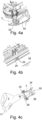
- a track structure SE with the aforementioned second guiding elements 55, normally being defined by a sequence of first type groups SS1, each with two subset of guiding faces for effecting a predefined pattern of rotations about the upright axis D of the clamps 20, and second type groups SS2 each including a guiding face for preventing rotation about the axis D of the clamps 20.
- groups of the track structure SE are shown cut away from adjacent groups for illustrative purposes in fig.
- two subsets of guiding faces generally may comprise pairs of opposite first elongated guiding faces 58', 58" at one vertical level for contacting the aforementioned first edges 34' of the lower structural part 32 and pairs of opposite second elongated guiding faces 60', 60" at lower vertical level for contacting the aforementioned second edges 35'.
- first and second guiding faces 58', 58", 60', 60" are arranged at a respective level, corresponding to the respective level below the conveyor 10 at which the first and second edges 34', 35' are advanced in the machine direction T, and serve to, upon sliding engagement with a corresponding edge 34', 35', rotate the lower structural part 32 with the clamp 20 relative to the upper structural part 36 about the vertical second axis D.
- Such a rotation by 90° may preferably take place as the clamp 20 leaves the first section 10, so that the horizontal first axis C then extends generally perpendicular to the machine direction T and the pig part 2 faces the direction of movement T as it moves along the second section 12, see fig. 1c .
- a rotation about the vertical second axis D may in particular be desirable for processing different surface portions of the suspended pig parts 2 at a given processing station 100, 200, 300, 400, 500, by guiding faces of selected configuration being located at the processing station.
- the lengthwise configuration of the guiding faces of one group SS1 may then vary along the extension of the processing station in the machine direction T, to rotate the pig part 2 about the vertical axis D as it passes through the processing station, see figs. 5h and 5i. Fig.
- 5i shows the first and second guiding faces that act together with the lower structural part 32 to provide a rack and pinion structure, with spaced apart upper teeth or rounded projections 97 and lower teeth or rounded projections 96 defining in part the respective first and second guiding faces 58', 60' along one side of the group SS1, at different vertical levels.
- the subelement configuration shown in fig. 5i allows for a progressive rotation of the pig part 2 of four times 45° as the pinion defined by the lower structural part 32 with tooth-like corners 99 passes along the processing station, thereby allowing processing of different surface portions of the pig part; as will be understood the upper and lower bodies 34, 35 alternatingly engage a corresponding subset of guiding faces to progressively bring about the rotation of the lower structural part 32 up to a predetermined angle of rotation when the coupling 30 is advanced in the machine direction T past the two subsets defining the first type group SS1.
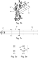
- the opposite guiding faces 58', 58", 60', 60" of the pairs defining a subset may alternatingly converge and diverge in the machine direction T, to control and initiate the rotation about the vertical axis D by sliding contact with the edges 34', 35' and/or corners 99 of the upper and lower body 34, 35.
- a base portion 64 of the track structure SE may be provided having an elongated track receiving the circular stem portion S of the lower structural part 32 located below the lower body 35, for providing sideways support for the coupling 30, see fig. 5j .
- a top cover plate 62 not shown in fig. 5f may be provided with a similar elongated track, for the same purpose.
- one guiding face 58', 60' configuration of one or the other of the aforementioned subsets will contact one of the corners 99 of the lower structural part 32 for initiating and temporarily maintaining a clockwise or anti-clockwise turning movement about the vertical axis D as the coupling 30 is advanced in the machine direction T, and an opposite guiding face 58", 60" configuration arranged downstream may then later contact another one of the corners of the lower structural part 32, for initiating and temporarily maintaining a further clockwise or anti-clockwise turning movement about the vertical axis D as the coupling 30 is advanced further in the machine direction T along a group SS1.
- the second guiding elements 55 are configured such that after completion of rotation of the lower structural part 32 about the vertical axis D by a desired angle some of the guiding faces will prevent any further, undesired rotation about the vertical axis D. This may be by the contact shown in fig.
- fig. 6 is shown the aforementioned last station 600 of the plant 1, wherein an activating element 610 is arranged on an elongated structure 608, to mechanically engage an arm 602 mounted onto each of the jaws 25 of the clamps 20 as the clamps 20 move along the overhead, third conveyor section 13.
- the pig part at this point has had most or all meat removed at the processing stations 100, 200, 300, 400, 500, and so the remaining portion still held by the clamp generally comprises only the bone, such as the hock bones or the fore shank bones shown in fig. 7 , depending on whether the situation shown in fig. 2f or in fig. 4c applies.
- the jaws 25 are first turned about their respective axis A against the force of the springs 28, to widen the gap G1, thereby allowing the pig part to be dropped from the clamp 20, into a collecting bin 601 as shown in fig. 1a .
- a further downwardly oriented face 610' gradually releases engagement with the arms 602, thereby returning the jaws 25 to their first position shown in figs. 2a-d , whereafter the clamps 20 are returned to the first station 40, ready to receive another pig part 2.
Landscapes
- Engineering & Computer Science (AREA)
- Life Sciences & Earth Sciences (AREA)
- Food Science & Technology (AREA)
- Wood Science & Technology (AREA)
- Zoology (AREA)
- Mechanical Engineering (AREA)
- Processing Of Meat And Fish (AREA)
Claims (8)
- Verarbeitungsanlage (1) für Teile (2) geschlachteter Schweine, beinhaltend eine Vielzahl von Verarbeitungsstationen (40, 100, 200, 300, 400, 500) für Schweineteile (2) und ein Förderband (10), das über jeweilige Kopplungen (30) eine Vielzahl von benachbarten Klemmstrukturen (20) zum Transportieren der Schweineteile (2) stützt, wobei das Förderband (10) die Kopplungen (30) mit einer jeweiligen Klemmstruktur (20) in einer Maschinenrichtung (T) vorschiebt,- wobei die Kopplungen (30) jeweils ein oberes Strukturteil (36) und ein unteres Strukturteil (32), die mit der Klemmstruktur (20) verbunden sind, umfassen,- wobei das untere Strukturteil (32) zur Drehung um eine vertikale Achse (D) relativ zu dem oberen Strukturteil (36) montiert ist,- wobei das untere Strukturteil (32) einen oberen Körper (34), der einen Umfang aufweist, der durch eine Anzahl an ersten Kanten (34'), die sich auf einer ersten Ebene erstrecken, definiert ist, und einen unteren Körper (35), der einen Umfang aufweist, der durch eine Anzahl an zweiten Kanten (35'), die sich auf einer niedrigeren zweiten Ebene erstrecken, definiert ist, umfasst,- wobei die Verarbeitungsanlage (1) ferner Folgendes beinhaltet:dadurch gekennzeichnet, dassi) einen Teilsatz von Führungsflächen (58', 58") auf der ersten Ebene zum Ineingriffnehmen des oberen Körpers (34), um eine Drehung um die vertikale Achse (D) zu bewirken, wenn die Kopplung (30) in der Maschinenrichtung (T) über den einen Teilsatz von Führungsflächen (58', 58") hinaus vorgeschoben wird, undii) einen anderen Teilsatz von Führungsflächen (60', 60") auf der zweiten Ebene zum Ineingriffnehmen des unteren Körpers (35), um eine Drehung um die vertikale Achse (D) zu bewirken, wenn die Kopplung (30) in der Maschinenrichtung (T) über den anderen Teilsatz von Führungsflächen (60', 60") hinaus vorgeschoben wird,- der obere und untere Körper (34, 35) aneinander befestigt sind,- der obere und untere Körper (34, 35) dieselbe Kontur aufweisen,- der obere Körper (34) in einem Winkel (α) um die vertikale Achse (D) relativ zu dem unteren Körper (35) winkelversetzt ist und- die Klemmstruktur (20) an dem unteren Körper (35) befestigt ist, und dass- die Anlage (1) den zwei Teilsätzen von Führungsflächen vorgelagert oder nachgelagert eine Gruppe (SS2) beinhaltet, die mindestens eine längliche Führungsfläche (GF1) umfasst, die sich entlang der Maschinenrichtung (T) auf einer oder der anderen der Ebenen erstreckt, um die Drehung des unteren Strukturteils (32) durch Ineingriffnahme einer Kante (34', 35') des oberen oder unteren Körpers (34, 35) zu verhindern oder zu begrenzen, oder- die Anlage (1) den zwei Teilsätzen von Führungsflächen vorgelagert und/oder nachgelagert eine Gruppe (SS2) von zwei länglichen Führungsflächen (GF1, GF2) beinhaltet, die beide auf einer oder der anderen der Ebenen einander gegenüberliegend angeordnet sind und sich entlang der Maschinenrichtung (T) erstrecken, um die Drehung durch Ineingriffnahme einer Kante (34', 35') des oberen oder unteren Körpers (34, 35) zu verhindern oder zu begrenzen.
- Anlage nach dem vorherigen Anspruch, wobei die zwei Teilsätze von Führungsflächen zusammen als eine Gruppe (SS1) entlang der Maschinenrichtung (T) angeordnet sind, wobei der obere und untere Körper (34, 35) abwechselnd die zwei Teilsätze von Führungsflächen in Eingriff nehmen, um schrittweise die Drehung des unteren Strukturteils (32) um die vertikale Achse (D) bis zu einem vorbestimmten Drehwinkel zu bewirken, wenn die Kopplung (30) in der Maschinenrichtung (T) über die Gruppe (SS1) hinaus vorgeschoben wird.
- Anlage nach Anspruch 1 oder 2, wobei die längliche(n) Führungsfläche(n) einen Eintrittsabschnitt zum Ausrichten mindestens einer der Kanten (34', 35') mit der/den länglichen Führungsfläche(n) durch Ineingriffnehmen des oberen oder unteren Körpers (34, 35) beinhaltet/beinhalten, um eine Drehung um die vertikale Achse (D) des unteren Strukturteils (32) zu bewirken, wenn die Kopplung (30) in der Maschinenrichtung (T) über den Eintrittsabschnitt hinaus vorgeschoben wird.
- Anlage nach einem der vorhergehenden Ansprüche, wobei sich sowohl bei dem ersten als auch dem zweiten Körper (34, 35) die Kanten (34', 35') an abgerundeten oder scharfen Ecken (99) treffen, wobei die erste und zweite Kante (34', 35') geradlinig sind.
- Anlage nach einem der vorhergehenden Ansprüche, wobei der obere und untere Körper (34, 35) jeweils die Kontur eines regulären n-seitigen Polygons aufweisen, wobei der Winkelversatz ein Winkel α von 360/(2 × n)° ist, wie etwa in der Form eines gleichseitigen Dreiecks, eines Quadrats oder eines Pentagons, bei denen der Winkelversatz 60°, 45° bzw. 36° beträgt.
- Anlage nach einem der vorhergehenden Ansprüche, wobei der untere Körper (35) schwenkbar mit einem Oberseitenabschnitt der Klemmstruktur (20) verbunden ist, um Drehung der Klemmstruktur (20) relativ zu dem unteren Körper (35) um eine horizontale Achse (C) zu ermöglichen.
- Anlage nach einem der vorhergehenden Ansprüche, wobei ein Schaftabschnitt (S) des unteren Strukturteils 32, der sich vorzugsweise unter dem unteren Körper (35) befindet, drehbar durch eine längliche Schiene aufgenommen ist, um eine seitliche im Allgemeinen horizontale Stütze für die Kopplung 30 bereitzustellen.
- Kopplung (30), umfassend ein oberes Strukturteil (36), das zur Verbindung mit einem darüberliegenden Förderband (10) konfiguriert ist, und ein unteres Strukturteil (32) mit einer Klemmstruktur (20) für ein Teil (2) eines geschlachteten Schweins,- wobei das untere Strukturteil (32) zur Drehung um eine vertikale Achse (D) relativ zu dem oberen Strukturteil (36) montiert ist,- wobei das untere Strukturteil (32) einen oberen Körper (34), der einen Umfang aufweist, der durch eine Anzahl an ersten Kanten (34') definiert ist, und einen unteren Körper (35), der einen Umfang aufweist, der durch eine Anzahl an zweiten Kanten (35') definiert ist, umfasst,- wobei der obere und untere Körper (34, 35) aneinander befestigt sind,- wobei der obere und untere Körper (34, 35) dieselbe Kontur aufweisen,- wobei der obere Körper (34) in einem Winkel (α) um die vertikale Achse (D) relativ zu dem unteren Körper (35) winkelversetzt ist,- wobei die Klemmstruktur (20) schwenkbar mit dem unteren Körper (35) verbunden ist,- wobei sich die Kanten (34', 35') an abgerundeten oder scharfen Ecken (99) treffen,- wobei die erste und zweite Kante (34', 35') geradlinig sind und- wobei der obere und untere Körper (34, 35) jeweils die Kontur eines regulären n-seitigen Polygons aufweisen, wie etwa in der Form eines gleichseitigen Dreiecks, eines Quadrats oder eines Pentagons, bei denen der Winkelversatz 60°, 45° bzw. 36° beträgt.
Applications Claiming Priority (3)
| Application Number | Priority Date | Filing Date | Title |
|---|---|---|---|
| DKPA201970167 | 2019-03-15 | ||
| DKPA201970184 | 2019-03-25 | ||
| PCT/EP2020/056668 WO2020187691A1 (en) | 2019-03-15 | 2020-03-12 | A slaughtered pig part processing plant, and a coupling for the plant |
Publications (3)
| Publication Number | Publication Date |
|---|---|
| EP3937643A1 EP3937643A1 (de) | 2022-01-19 |
| EP3937643B1 true EP3937643B1 (de) | 2024-09-25 |
| EP3937643C0 EP3937643C0 (de) | 2024-09-25 |
Family
ID=69810861
Family Applications (1)
| Application Number | Title | Priority Date | Filing Date |
|---|---|---|---|
| EP20711148.5A Active EP3937643B1 (de) | 2019-03-15 | 2020-03-12 | Bearbeitungsanlage für schlachttierteilen, und kupplung für die anlage |
Country Status (5)
| Country | Link |
|---|---|
| US (1) | US11950603B2 (de) |
| EP (1) | EP3937643B1 (de) |
| ES (1) | ES3000433T3 (de) |
| PL (1) | PL3937643T3 (de) |
| WO (1) | WO2020187691A1 (de) |
Families Citing this family (3)
| Publication number | Priority date | Publication date | Assignee | Title |
|---|---|---|---|---|
| CN113620028B (zh) * | 2021-08-11 | 2022-12-30 | 哈特盈致(中山)智能科技有限公司 | 一种电机盖板自动上料设备及方法 |
| CN114275530B (zh) * | 2022-01-29 | 2025-05-30 | 苏州藤岛自动化设备有限公司 | 一种90度翻转夹爪治具 |
| CN114313912B (zh) * | 2022-01-30 | 2022-09-20 | 华中科技大学 | 一种随行夹具的定位夹紧装置及产线转移系统 |
Family Cites Families (10)
| Publication number | Priority date | Publication date | Assignee | Title |
|---|---|---|---|---|
| NL1014845C1 (nl) | 1999-06-11 | 2000-12-12 | Stork Pmt | Inrichting voor het verwerken van een slachtproduct. |
| CA2535075A1 (en) | 2003-08-27 | 2005-03-10 | Mayekawa Mfg. Co., Ltd. | Meat dressing/boning method and system therefor |
| DK3508064T3 (da) | 2009-12-17 | 2021-02-01 | Marel Meat Bv | System and method for processing slaughtered animals and/or parts thereof |
| US8757354B2 (en) | 2010-04-19 | 2014-06-24 | Foodmate Bv | Turning block alignment |
| NL2006075C2 (en) | 2011-01-26 | 2012-07-30 | Foodmate B V | Rotationally indexed article support for a conveyor system having an alignment station. |
| PL2560496T3 (pl) | 2010-04-19 | 2015-08-31 | Foodmate Bv | Obrotowy wspornik produktu dla pasa transportowego |
| JP6185579B2 (ja) | 2012-07-04 | 2017-08-23 | マレル・ミート・プロセッシング・ベー・フェー | 四肢屠畜動物の枝肉または枝肉の部位を運搬するためのシステム |
| NL2010580C2 (en) | 2013-04-05 | 2014-10-07 | Marel Stork Poultry Proc Bv | Shackle for hanging poultry transportation, poultry cooling unit, method for cooling of hanging poultry and method for hanging poultry carcasses to poultry shackles. |
| NL2012386B1 (nl) * | 2014-03-10 | 2015-11-26 | Marel Stork Poultry Proc Bv | Inrichting en werkwijze voor het wijzigen van de oriëntatie van slachtproducten. |
| EP3146848B1 (de) * | 2015-09-23 | 2019-11-13 | Meyn Food Processing Technology B.V. | Fördersystem und in diesem fördersystem verwendeter träger für geflügel |
-
2020
- 2020-03-12 WO PCT/EP2020/056668 patent/WO2020187691A1/en not_active Ceased
- 2020-03-12 EP EP20711148.5A patent/EP3937643B1/de active Active
- 2020-03-12 ES ES20711148T patent/ES3000433T3/es active Active
- 2020-03-12 PL PL20711148.5T patent/PL3937643T3/pl unknown
- 2020-03-12 US US17/439,216 patent/US11950603B2/en active Active
Also Published As
| Publication number | Publication date |
|---|---|
| US11950603B2 (en) | 2024-04-09 |
| EP3937643A1 (de) | 2022-01-19 |
| PL3937643T3 (pl) | 2025-01-13 |
| ES3000433T3 (en) | 2025-02-28 |
| US20220159978A1 (en) | 2022-05-26 |
| WO2020187691A1 (en) | 2020-09-24 |
| EP3937643C0 (de) | 2024-09-25 |
Similar Documents
| Publication | Publication Date | Title |
|---|---|---|
| US11877580B2 (en) | Slaughtered pig part processing plant, a clamp structure for retaining a slaughtered pig part, and a method of retaining a slaughtered pig part by a clamp structure | |
| EP3937643B1 (de) | Bearbeitungsanlage für schlachttierteilen, und kupplung für die anlage | |
| EP1769681B1 (de) | Verfahren und Vorrichtung zur Bearbeitung des Organpakets eines Schlachttieres | |
| USRE32697E (en) | Device and method for cutting slaughtered poultry in separate pieces | |
| US6283848B1 (en) | Poultry foot harvester and method | |
| DE69221723T2 (de) | Anlage zur bearbeitung von geflügel | |
| US5697837A (en) | Poultry breast filleting apparatus | |
| KR101861466B1 (ko) | 컨베이어 섹션을 따라 이송하는 방향으로 단일 파일로 이송된 가금류 다리를 위치잡기 위한 위치 장치 및 가금류 다리로부터 넓적다리 고기를 분리하기 위하여 위치잡기를 포함하는 방법 | |
| CN112690317B (zh) | 对禽类腿或禽类腿的一部分去皮的去皮装置和方法 | |
| US3685096A (en) | Apparatus for eviscerating chickens or other fowl | |
| US5672100A (en) | Method for suspending live poultry by the legs and an apparatus, catching means and slaughter shackle for carrying out the method | |
| AU2024227076A1 (en) | Automated wool harvesting | |
| JP6719547B2 (ja) | 屠体の肩肉から肩甲骨を自動的に緩める又は除去するためのシステム及び方法 | |
| US3571845A (en) | Chicken-slaughtering mechanism | |
| US5938522A (en) | Bacon hanger | |
| US12150456B2 (en) | Crustacean butchering apparatus | |
| EP1190625A1 (de) | Verfahren und Vorrichtung zum Filetieren von Fischen | |
| EP1374687A1 (de) | Vorrichtung und Verfahren zum automatisierten Trennen von Organen aus einem Geschlinge | |
| US20220408740A1 (en) | A slaughtered pig part processing plant with a pig part deskinner, and a slaughtered pig part deskinner unit | |
| US20200214302A1 (en) | Apparatus and method for deboning poultry breasts | |
| EP2056678B1 (de) | Ablegen von schlachttierhälften | |
| FR2931339A1 (fr) | Arrachage automatise de peaux d'animaux de boucherie. | |
| JP2930927B2 (ja) | 抜取り収穫機の収穫部 | |
| DE2817847C2 (de) | Verfahren und Vorrichtung zum Beschicken von Fischbearbeitungsmaschinen | |
| JPS5854949Y2 (ja) | 燻煙用ケ−シングの結「さつ」金具除去装置 |
Legal Events
| Date | Code | Title | Description |
|---|---|---|---|
| STAA | Information on the status of an ep patent application or granted ep patent |
Free format text: STATUS: UNKNOWN |
|
| STAA | Information on the status of an ep patent application or granted ep patent |
Free format text: STATUS: THE INTERNATIONAL PUBLICATION HAS BEEN MADE |
|
| PUAI | Public reference made under article 153(3) epc to a published international application that has entered the european phase |
Free format text: ORIGINAL CODE: 0009012 |
|
| STAA | Information on the status of an ep patent application or granted ep patent |
Free format text: STATUS: REQUEST FOR EXAMINATION WAS MADE |
|
| 17P | Request for examination filed |
Effective date: 20210908 |
|
| AK | Designated contracting states |
Kind code of ref document: A1 Designated state(s): AL AT BE BG CH CY CZ DE DK EE ES FI FR GB GR HR HU IE IS IT LI LT LU LV MC MK MT NL NO PL PT RO RS SE SI SK SM TR |
|
| DAV | Request for validation of the european patent (deleted) | ||
| DAX | Request for extension of the european patent (deleted) | ||
| GRAP | Despatch of communication of intention to grant a patent |
Free format text: ORIGINAL CODE: EPIDOSNIGR1 |
|
| RIC1 | Information provided on ipc code assigned before grant |
Ipc: B65G 47/244 20060101ALI20240322BHEP Ipc: B65G 17/20 20060101ALI20240322BHEP Ipc: A22B 7/00 20060101AFI20240322BHEP |
|
| STAA | Information on the status of an ep patent application or granted ep patent |
Free format text: STATUS: GRANT OF PATENT IS INTENDED |
|
| INTG | Intention to grant announced |
Effective date: 20240502 |
|
| GRAS | Grant fee paid |
Free format text: ORIGINAL CODE: EPIDOSNIGR3 |
|
| GRAA | (expected) grant |
Free format text: ORIGINAL CODE: 0009210 |
|
| STAA | Information on the status of an ep patent application or granted ep patent |
Free format text: STATUS: THE PATENT HAS BEEN GRANTED |
|
| AK | Designated contracting states |
Kind code of ref document: B1 Designated state(s): AL AT BE BG CH CY CZ DE DK EE ES FI FR GB GR HR HU IE IS IT LI LT LU LV MC MK MT NL NO PL PT RO RS SE SI SK SM TR |
|
| REG | Reference to a national code |
Ref country code: GB Ref legal event code: FG4D |
|
| REG | Reference to a national code |
Ref country code: CH Ref legal event code: EP |
|
| REG | Reference to a national code |
Ref country code: DE Ref legal event code: R096 Ref document number: 602020038268 Country of ref document: DE |
|
| REG | Reference to a national code |
Ref country code: IE Ref legal event code: FG4D |
|
| U01 | Request for unitary effect filed |
Effective date: 20241011 |
|
| U07 | Unitary effect registered |
Designated state(s): AT BE BG DE DK EE FI FR IT LT LU LV MT NL PT RO SE SI Effective date: 20241030 |
|
| PG25 | Lapsed in a contracting state [announced via postgrant information from national office to epo] |
Ref country code: NO Free format text: LAPSE BECAUSE OF FAILURE TO SUBMIT A TRANSLATION OF THE DESCRIPTION OR TO PAY THE FEE WITHIN THE PRESCRIBED TIME-LIMIT Effective date: 20241225 |
|
| PG25 | Lapsed in a contracting state [announced via postgrant information from national office to epo] |
Ref country code: GR Free format text: LAPSE BECAUSE OF FAILURE TO SUBMIT A TRANSLATION OF THE DESCRIPTION OR TO PAY THE FEE WITHIN THE PRESCRIBED TIME-LIMIT Effective date: 20241226 |
|
| PG25 | Lapsed in a contracting state [announced via postgrant information from national office to epo] |
Ref country code: RS Free format text: LAPSE BECAUSE OF FAILURE TO SUBMIT A TRANSLATION OF THE DESCRIPTION OR TO PAY THE FEE WITHIN THE PRESCRIBED TIME-LIMIT Effective date: 20241225 |
|
| PG25 | Lapsed in a contracting state [announced via postgrant information from national office to epo] |
Ref country code: RS Free format text: LAPSE BECAUSE OF FAILURE TO SUBMIT A TRANSLATION OF THE DESCRIPTION OR TO PAY THE FEE WITHIN THE PRESCRIBED TIME-LIMIT Effective date: 20241225 Ref country code: NO Free format text: LAPSE BECAUSE OF FAILURE TO SUBMIT A TRANSLATION OF THE DESCRIPTION OR TO PAY THE FEE WITHIN THE PRESCRIBED TIME-LIMIT Effective date: 20241225 Ref country code: GR Free format text: LAPSE BECAUSE OF FAILURE TO SUBMIT A TRANSLATION OF THE DESCRIPTION OR TO PAY THE FEE WITHIN THE PRESCRIBED TIME-LIMIT Effective date: 20241226 |
|
| U20 | Renewal fee for the european patent with unitary effect paid |
Year of fee payment: 6 Effective date: 20250123 |
|
| REG | Reference to a national code |
Ref country code: ES Ref legal event code: FG2A Ref document number: 3000433 Country of ref document: ES Kind code of ref document: T3 Effective date: 20250228 |
|
| PG25 | Lapsed in a contracting state [announced via postgrant information from national office to epo] |
Ref country code: IS Free format text: LAPSE BECAUSE OF FAILURE TO SUBMIT A TRANSLATION OF THE DESCRIPTION OR TO PAY THE FEE WITHIN THE PRESCRIBED TIME-LIMIT Effective date: 20250125 |
|
| PG25 | Lapsed in a contracting state [announced via postgrant information from national office to epo] |
Ref country code: SM Free format text: LAPSE BECAUSE OF FAILURE TO SUBMIT A TRANSLATION OF THE DESCRIPTION OR TO PAY THE FEE WITHIN THE PRESCRIBED TIME-LIMIT Effective date: 20240925 |
|
| PG25 | Lapsed in a contracting state [announced via postgrant information from national office to epo] |
Ref country code: CZ Free format text: LAPSE BECAUSE OF FAILURE TO SUBMIT A TRANSLATION OF THE DESCRIPTION OR TO PAY THE FEE WITHIN THE PRESCRIBED TIME-LIMIT Effective date: 20240925 |
|
| PGFP | Annual fee paid to national office [announced via postgrant information from national office to epo] |
Ref country code: PL Payment date: 20250225 Year of fee payment: 6 |
|
| PG25 | Lapsed in a contracting state [announced via postgrant information from national office to epo] |
Ref country code: SK Free format text: LAPSE BECAUSE OF FAILURE TO SUBMIT A TRANSLATION OF THE DESCRIPTION OR TO PAY THE FEE WITHIN THE PRESCRIBED TIME-LIMIT Effective date: 20240925 |
|
| PGFP | Annual fee paid to national office [announced via postgrant information from national office to epo] |
Ref country code: ES Payment date: 20250523 Year of fee payment: 6 |
|
| PLBE | No opposition filed within time limit |
Free format text: ORIGINAL CODE: 0009261 |
|
| STAA | Information on the status of an ep patent application or granted ep patent |
Free format text: STATUS: NO OPPOSITION FILED WITHIN TIME LIMIT |
|
| 26N | No opposition filed |
Effective date: 20250626 |
|
| PG25 | Lapsed in a contracting state [announced via postgrant information from national office to epo] |
Ref country code: MC Free format text: LAPSE BECAUSE OF FAILURE TO SUBMIT A TRANSLATION OF THE DESCRIPTION OR TO PAY THE FEE WITHIN THE PRESCRIBED TIME-LIMIT Effective date: 20240925 |
|
| REG | Reference to a national code |
Ref country code: CH Ref legal event code: H13 Free format text: ST27 STATUS EVENT CODE: U-0-0-H10-H13 (AS PROVIDED BY THE NATIONAL OFFICE) Effective date: 20251023 |
|
| GBPC | Gb: european patent ceased through non-payment of renewal fee |
Effective date: 20250312 |
|
| PG25 | Lapsed in a contracting state [announced via postgrant information from national office to epo] |
Ref country code: GB Free format text: LAPSE BECAUSE OF NON-PAYMENT OF DUE FEES Effective date: 20250312 |
|
| PG25 | Lapsed in a contracting state [announced via postgrant information from national office to epo] |
Ref country code: HR Free format text: LAPSE BECAUSE OF FAILURE TO SUBMIT A TRANSLATION OF THE DESCRIPTION OR TO PAY THE FEE WITHIN THE PRESCRIBED TIME-LIMIT Effective date: 20240925 |
|
| PG25 | Lapsed in a contracting state [announced via postgrant information from national office to epo] |
Ref country code: CH Free format text: LAPSE BECAUSE OF NON-PAYMENT OF DUE FEES Effective date: 20250331 |
|
| PG25 | Lapsed in a contracting state [announced via postgrant information from national office to epo] |
Ref country code: IE Free format text: LAPSE BECAUSE OF NON-PAYMENT OF DUE FEES Effective date: 20250312 |
|
| U20 | Renewal fee for the european patent with unitary effect paid |
Year of fee payment: 7 Effective date: 20260129 |