EP3936090B1 - Applikator für kaltbehandlung - Google Patents
Applikator für kaltbehandlung Download PDFInfo
- Publication number
- EP3936090B1 EP3936090B1 EP20185027.8A EP20185027A EP3936090B1 EP 3936090 B1 EP3936090 B1 EP 3936090B1 EP 20185027 A EP20185027 A EP 20185027A EP 3936090 B1 EP3936090 B1 EP 3936090B1
- Authority
- EP
- European Patent Office
- Prior art keywords
- applicator
- applicator housing
- channel body
- housing
- recess
- Prior art date
- Legal status (The legal status is an assumption and is not a legal conclusion. Google has not performed a legal analysis and makes no representation as to the accuracy of the status listed.)
- Active
Links
Images


Classifications
-
- A—HUMAN NECESSITIES
- A61—MEDICAL OR VETERINARY SCIENCE; HYGIENE
- A61B—DIAGNOSIS; SURGERY; IDENTIFICATION
- A61B18/00—Surgical instruments, devices or methods for transferring non-mechanical forms of energy to or from the body
- A61B18/02—Surgical instruments, devices or methods for transferring non-mechanical forms of energy to or from the body by cooling, e.g. cryogenic techniques
-
- A—HUMAN NECESSITIES
- A61—MEDICAL OR VETERINARY SCIENCE; HYGIENE
- A61F—FILTERS IMPLANTABLE INTO BLOOD VESSELS; PROSTHESES; DEVICES PROVIDING PATENCY TO, OR PREVENTING COLLAPSING OF, TUBULAR STRUCTURES OF THE BODY, e.g. STENTS; ORTHOPAEDIC, NURSING OR CONTRACEPTIVE DEVICES; FOMENTATION; TREATMENT OR PROTECTION OF EYES OR EARS; BANDAGES, DRESSINGS OR ABSORBENT PADS; FIRST-AID KITS
- A61F7/00—Heating or cooling appliances for medical or therapeutic treatment of the human body
-
- A—HUMAN NECESSITIES
- A61—MEDICAL OR VETERINARY SCIENCE; HYGIENE
- A61B—DIAGNOSIS; SURGERY; IDENTIFICATION
- A61B18/00—Surgical instruments, devices or methods for transferring non-mechanical forms of energy to or from the body
- A61B18/02—Surgical instruments, devices or methods for transferring non-mechanical forms of energy to or from the body by cooling, e.g. cryogenic techniques
- A61B18/0218—Surgical instruments, devices or methods for transferring non-mechanical forms of energy to or from the body by cooling, e.g. cryogenic techniques with open-end cryogenic probe, e.g. for spraying fluid directly on tissue or via a tissue-contacting porous tip
-
- A—HUMAN NECESSITIES
- A61—MEDICAL OR VETERINARY SCIENCE; HYGIENE
- A61F—FILTERS IMPLANTABLE INTO BLOOD VESSELS; PROSTHESES; DEVICES PROVIDING PATENCY TO, OR PREVENTING COLLAPSING OF, TUBULAR STRUCTURES OF THE BODY, e.g. STENTS; ORTHOPAEDIC, NURSING OR CONTRACEPTIVE DEVICES; FOMENTATION; TREATMENT OR PROTECTION OF EYES OR EARS; BANDAGES, DRESSINGS OR ABSORBENT PADS; FIRST-AID KITS
- A61F7/00—Heating or cooling appliances for medical or therapeutic treatment of the human body
- A61F7/08—Warming pads, pans or mats; Hot-water bottles
-
- A—HUMAN NECESSITIES
- A61—MEDICAL OR VETERINARY SCIENCE; HYGIENE
- A61B—DIAGNOSIS; SURGERY; IDENTIFICATION
- A61B18/00—Surgical instruments, devices or methods for transferring non-mechanical forms of energy to or from the body
- A61B2018/00315—Surgical instruments, devices or methods for transferring non-mechanical forms of energy to or from the body for treatment of particular body parts
- A61B2018/00452—Skin
- A61B2018/0047—Upper parts of the skin, e.g. skin peeling or treatment of wrinkles
-
- A—HUMAN NECESSITIES
- A61—MEDICAL OR VETERINARY SCIENCE; HYGIENE
- A61B—DIAGNOSIS; SURGERY; IDENTIFICATION
- A61B18/00—Surgical instruments, devices or methods for transferring non-mechanical forms of energy to or from the body
- A61B2018/00982—Surgical instruments, devices or methods for transferring non-mechanical forms of energy to or from the body combined with or comprising means for visual or photographic inspections inside the body, e.g. endoscopes
-
- A—HUMAN NECESSITIES
- A61—MEDICAL OR VETERINARY SCIENCE; HYGIENE
- A61F—FILTERS IMPLANTABLE INTO BLOOD VESSELS; PROSTHESES; DEVICES PROVIDING PATENCY TO, OR PREVENTING COLLAPSING OF, TUBULAR STRUCTURES OF THE BODY, e.g. STENTS; ORTHOPAEDIC, NURSING OR CONTRACEPTIVE DEVICES; FOMENTATION; TREATMENT OR PROTECTION OF EYES OR EARS; BANDAGES, DRESSINGS OR ABSORBENT PADS; FIRST-AID KITS
- A61F7/00—Heating or cooling appliances for medical or therapeutic treatment of the human body
- A61F2007/0001—Body part
- A61F2007/0052—Body part for treatment of skin or hair
-
- A—HUMAN NECESSITIES
- A61—MEDICAL OR VETERINARY SCIENCE; HYGIENE
- A61F—FILTERS IMPLANTABLE INTO BLOOD VESSELS; PROSTHESES; DEVICES PROVIDING PATENCY TO, OR PREVENTING COLLAPSING OF, TUBULAR STRUCTURES OF THE BODY, e.g. STENTS; ORTHOPAEDIC, NURSING OR CONTRACEPTIVE DEVICES; FOMENTATION; TREATMENT OR PROTECTION OF EYES OR EARS; BANDAGES, DRESSINGS OR ABSORBENT PADS; FIRST-AID KITS
- A61F7/00—Heating or cooling appliances for medical or therapeutic treatment of the human body
- A61F2007/0059—Heating or cooling appliances for medical or therapeutic treatment of the human body with an open fluid circuit
- A61F2007/0063—Heating or cooling appliances for medical or therapeutic treatment of the human body with an open fluid circuit for cooling
- A61F2007/0068—Heating or cooling appliances for medical or therapeutic treatment of the human body with an open fluid circuit for cooling evaporating on the spot to be cooled
-
- A—HUMAN NECESSITIES
- A61—MEDICAL OR VETERINARY SCIENCE; HYGIENE
- A61F—FILTERS IMPLANTABLE INTO BLOOD VESSELS; PROSTHESES; DEVICES PROVIDING PATENCY TO, OR PREVENTING COLLAPSING OF, TUBULAR STRUCTURES OF THE BODY, e.g. STENTS; ORTHOPAEDIC, NURSING OR CONTRACEPTIVE DEVICES; FOMENTATION; TREATMENT OR PROTECTION OF EYES OR EARS; BANDAGES, DRESSINGS OR ABSORBENT PADS; FIRST-AID KITS
- A61F7/00—Heating or cooling appliances for medical or therapeutic treatment of the human body
- A61F2007/0087—Hand-held applicators
-
- A—HUMAN NECESSITIES
- A61—MEDICAL OR VETERINARY SCIENCE; HYGIENE
- A61F—FILTERS IMPLANTABLE INTO BLOOD VESSELS; PROSTHESES; DEVICES PROVIDING PATENCY TO, OR PREVENTING COLLAPSING OF, TUBULAR STRUCTURES OF THE BODY, e.g. STENTS; ORTHOPAEDIC, NURSING OR CONTRACEPTIVE DEVICES; FOMENTATION; TREATMENT OR PROTECTION OF EYES OR EARS; BANDAGES, DRESSINGS OR ABSORBENT PADS; FIRST-AID KITS
- A61F7/00—Heating or cooling appliances for medical or therapeutic treatment of the human body
- A61F2007/0093—Heating or cooling appliances for medical or therapeutic treatment of the human body programmed
-
- A—HUMAN NECESSITIES
- A61—MEDICAL OR VETERINARY SCIENCE; HYGIENE
- A61F—FILTERS IMPLANTABLE INTO BLOOD VESSELS; PROSTHESES; DEVICES PROVIDING PATENCY TO, OR PREVENTING COLLAPSING OF, TUBULAR STRUCTURES OF THE BODY, e.g. STENTS; ORTHOPAEDIC, NURSING OR CONTRACEPTIVE DEVICES; FOMENTATION; TREATMENT OR PROTECTION OF EYES OR EARS; BANDAGES, DRESSINGS OR ABSORBENT PADS; FIRST-AID KITS
- A61F7/00—Heating or cooling appliances for medical or therapeutic treatment of the human body
- A61F2007/0095—Heating or cooling appliances for medical or therapeutic treatment of the human body with a temperature indicator
Definitions
- the invention relates to an applicator for cold treatment, e.g., of skin disorders, such as warts, age spots, tick bites, skintags, etc., the applicator being mountable on a pressurized dispenser with a nozzle, the applicator having a leak tight tip for contacting a spot to be treated, the tip being cooled by refrigerant released from the nozzle.
- an applicator for cold treatment e.g., of skin disorders, such as warts, age spots, tick bites, skintags, etc.
- the object of the present invention is to provide a system with reduced risk of leakage or spilling of refrigerant liquid.
- an applicator comprising an applicator housing with an inlet opening and a leak tight tip, the applicator housing enclosing a channel body extending between the inlet opening and the leak tight tip;
- the cooling effect is delayed until the release openings are opened.
- the one or more release openings are closed, so in this position the refrigerant cannot significantly evaporate and extract heat. Only after the one or more release openings are at least partly opened, e.g., by moving the applicator from the pressed position, the release openings allow the refrigerant to expand and evaporate. As a result, cooling takes place only after moving the applicator from the pressed position.
- the applicator can be separated from the pressurized dispenser for the desired treatment.
- the pressurized dispenser can be kept away from the skin to be treated, so the risk of spillage and skin injuries is substantially reduced.
- the applicator further comprises a coupler with a lower side mountable or mounted to the pressurized dispenser, and an upper side provided with a coupler recess;
- the nozzle After mounting the applicator on the dispenser, the nozzle projects through the nozzle passage opening and connects to the inlet opening.
- the applicator housing can easily be separated from the coupler and the pressurized dispenser.
- the release openings can be positioned in parts of the applicator housing received in the coupler recess when the applicator is in the pressed position, so the coupler recess closes the release openings in that position.
- the channel body comprises capillary channels extending between the nozzle engaging end and the leak tight tip.
- Capillary channels are channels which are too small to allow evaporation of the refrigerant liquid. This helps to delay the cooling effect.
- the capillary channels may for example have a largest diameter of at most 100 pm, e., at most 75 pm, e.g., at least 20 pm.
- the channel body can for example be formed of a thermally insulating material, such as a plastic material, such as capillary foam, e.g., of a capillary polyester foam.
- the channel body can for example be made of a highlighter felt material, in particular of a highlighter felt polyester. Such material comprises a high density of straight and parallel capillary channels, allowing fast transport of refrigerant liquid towards the leak tight tip.
- the cooling effect increases with the length of the channel body.
- the length of the channel body can be selected on basis of the desired cooling effect for treatment of a certain skin disorder.
- the side wall or side walls of the channel body is/are sealed by a liner, preventing refrigerant from escaping via the side wall.
- a channel body of highlighter felt material with a side wall or side walls sealed by a liner, and with top and bottom faces without the liner, the capillary channels running between the top and bottom faces.
- the leak tight tip provides a contact surface for contacting a spot to be treated.
- the leak tight tip will typically be of a heat conductive material, e.g., having a thermal conductivity of at least 10 Wm -1 K -1 . Suitable materials are for instance metals, in particular stainless steel, titanium, aluminum or alloys thereof.
- the tip is leak tight, meaning that the refrigerant liquid cannot permeate through the tip and cannot leak between the tip and the adjacent sections of the applicator housing.
- the applicator housing of the applicator has walls spaced from the channel body. This helps to define a suitable flow path towards release openings in the walls of the applicator housing.
- the spacing between the walls and the channel body is for example at most 3,5 mm.
- the bottom of the applicator housing comprises an inwardly protruding part of the bottom comprising the inlet opening and spacing a bottom face of the channel body from the bottom of the applicator housing, so the bottom of the channel body is not completely blocked by the bottom of the applicator housing.
- the tip is formed by an insert partly received in a recess of the top end of the channel body and an opening of the applicator housing in line with the recess in the channel body.
- the insert may for example be a metal insert or an insert of a material impregnated with a therapeutically active ingredient.
- the applicator housing can comprise a slit which can elastically be forced, e.g., by pinching or pressing, to move from a closed rest position to an open position. In the closed position the leak tight tip is covered and in the open position the leak tight tip is exposed and ready for use.
- a slit which can elastically be forced, e.g., by pinching or pressing, to move from a closed rest position to an open position. In the closed position the leak tight tip is covered and in the open position the leak tight tip is exposed and ready for use.
- Such an embodiment is particularly useful for the treatment of skin tags or tick bites.
- the applicator housing is pressed down, as described above. Then, while the applicator housing is removed from the pressurized dispenser, the refrigerant escapes and the delayed cooling effect starts.
- the slit is then forced apart and put on the skin tag or biting tick.
- the slit is then released and pinches the skin tag or biting tick while the treated disorder is cooled by the cooled
- the invention also pertains to an assembly of an applicator and a matching pressurized dispenser containing a refrigerant liquid.
- the pressurized dispenser can for example be of the standard type aerosol container or spray can having a top end with a circumferential seam joint around the nozzle. This seam joint can be used for a snap connection with a matching circumferential recess at the lower end of the coupler.
- the present disclosure also pertains to an applicator comprising an applicator housing with an inlet opening and a leak tight tip, the applicator housing enclosing a capillary channel body as described above, with capillary channels extending between the inlet opening and the leak tight tip; the applicator being mounted or mountable in a releasable manner onto a top end of an pressurized dispenser comprising a nozzle, such that the inlet opening is in fluid communication with the nozzle, the mounted applicator housing being moveable between a rest position and a pressed position to activate the nozzle.
- an applicator for cold treatment optionally comprising any one of the features as disclosed above, comprising an applicator housing with an inlet opening and a leak tight tip, wherein the applicator housing comprises a slit which can elastically be forced to move from a closed rest position, covering the leak tight tip, to an open position, exposing the leak tight tip.
- the applicator of the present invention can for example be used for the treatment of skin disorders, such as warts, age spots, skin tags, burns, insect bites, rings or bags under the eyes, bruises or swellings.
- skin disorders such as warts, age spots, skin tags, burns, insect bites, rings or bags under the eyes, bruises or swellings.
- a single dispenser can be combined with interchangeable applicators having different tips for different skin disorders. Similarly, when the dispenser is empty, it can easily be replaced by a filled one, without disposing the applicator.
- Suitable refrigerant liquids include volatile hydrocarbons, such as methyl ether, dimethyl ether, liquid hydrofluoro-olefins, n-butane, isobutane or propane. Nitrous oxide and carbon dioxide can also be used.
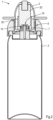
- Figure 1 shows an assembly 1 of a pressurized dispenser 2 and an applicator 3 for cold treatment.
- the applicator 3 comprises a coupler 4 and an applicator housing 5.
- the assembly 1 is shown in cross section and is essentially cylindrically symmetrical about its longitudinal axis L.
- the pressurized dispenser 2 is shaped as a standard aerosol container with a top end having a circumferential seam joint 6 around a nozzle 7.
- the pressurized dispenser 2 contains a refrigerant liquid. Pressing down the nozzle 7 releases the refrigerant liquid from the pressurized dispenser 2 via the nozzle 7.
- the coupler 4 has a lower end with a circumferential recess 8 forming a releasable snap fit or clamp fit connection with the seam joint 6 of the pressurized dispenser 2.
- the coupler 4 has an upper end provided with a coupler recess 9 receiving the applicator housing 5.
- the coupler recess 9 and the applicator housing 5 have matching cylindrical outlines so the applicator housing 5 fits within the coupler recess 9 and can be freely slid up and down within the coupler recess 9.
- Other outlines can also be used as long as the applicator housing 5 fits within the coupler recess 9 only allowing movement guided by the shape of the coupler recess 9, e.g., a sliding fit allowing sliding movement in a direction parallel to the longitudinal axis L of the assembly 1.
- the coupler recess 9 has a bottom 10 with a central nozzle passage opening 11.
- the nozzle 7 of the pressurized dispenser 2 projects through the nozzle passage opening 11.
- the bottom of the coupler recess 9 is substantially flush with an upper face of a base 12 of the nozzle 7.
- the applicator housing 5 has a cylindrical lower end 13 fitting within the coupler recess 9, and a substantially conical truncated top end 14. Between the top end 14 and the lower end 13, the applicator housing 5 has two oppositely extending flanges 15 providing grip for a user and allowing the user to push down the applicator housing 5.
- the lower end 13 of the applicator housing 5 has a bottom with an inwardly protruding cylindrical part 16 receiving a tip 17 of the nozzle 7.
- This protruding part 16 is provided with a central inlet opening 18 aligned with the nozzle tip 17.
- the applicator housing 5 has an interior space 19 enclosing a channel body 20.
- the channel body 20 extends between the protruding bottom part 16 and the top end of the applicator housing 5.
- a set of fins 21 extending upward from the bottom of the applicator housing 5, serve to lock the channel body 20 in place.
- the channel body 20 is wider than the protruding bottom part 16. As a result, the lower end of the channel body 20 protrudes from all sides with respect to the protruding bottom part 16.
- the lower end of the channel body 20 comprises a section 22 in fluid communication with the nozzle 7.
- the section 22 is formed by a recess receiving the outer tip of the protruding bottom part 16.
- the channel body 20 is cylindrical or it may have any other suitable outline.
- the channel body 20 is made of a highlighter felt polyester. This is a foamy material with numerous capillary channels extending in a direction substantially parallel to the longitudinal axis of the assembly, i.e., from the nozzle to the top end of the applicator housing 5.
- the cylindrical side wall of the channel body is sealed by a liner 27, which is substantially impermeable for refrigerant liquid and refrigerant vapour. Due to the liner 27 any refrigerant liquid can only flow via the bottom section of the channel body 20.
- the truncated top end 14 of the applicator housing 5 is provided with a leak tight tip 23 of a thermally conductive material, in particular stainless steel, chromated copper or a similar metal.
- This tip 23 is formed by an insert partly received in a matching recess 24 at the top side of the channel body 20 and protruding through a matching opening 25 in the truncated top end of the applicator housing 5. Any gap between the opening 25 and the insert 24 is sealed to prevent any leakage of refrigerant liquid.
- the wall of the applicator housing 5 has a number of release openings 26 just below the flanges 15.
- the walls of the applicator housing 5 are spaced from the channel body 20.
- the bottom 10 of the applicator housing 5 is spaced from the channel body 20, except where the channel body 20 is supported by the inward protruding bottom part 16, so as to create a direct flow path from the bottom of the channel body 20 to the release openings 26.
- Figure 1 shows the assembly 1 with the applicator housing 5 in a rest position, with the applicator housing 5 passively resting on top of the nozzle 7 of the pressurized dispenser 2. In this position, the release openings 26 are not closed and the interior spacing of the applicator housing 5 is in open communication with the ambient air via the release openings 26.
- the user can push down the applicator housing 5 into a pressed position, as shown in Figure 2 .
- the release openings 26 are fully closed by the wall of the coupler recess 9 and the nozzle 7 of the pressurized dispenser 2 is pressed down.
- Liquid refrigerant is dispensed from the nozzle 7 via the inlet opening 18 in the protruding bottom part 16 into the capillary channels of the channel body 20.
- the capillary channels are too small to allow evaporation of the refrigerant liquid.
- the user can then lift the applicator housing 5.
- the nozzle 7 stops dispensing the refrigerant liquid from the pressurized dispenser 2.
- the release openings 26 are opened allowing refrigerant vapour to escape.
- Liquid refrigerant in the applicator housing 5 is now free to evaporate and extracts heat from the thermally conductive leak tight tip 23.
- the user can simply remove the applicator housing 5 from the coupler 4 and treat the skin disorder with the cooled leak tight tip 23, while keeping distance from the pressurized dispenser 2, as shown in Figure 3 , which shows treatment of a disorder on a person's finger 29.
- the relatively small applicator housing 5 is easy to handle compared to prior art applicator heads which remain coupled to the dispenser during treatment.
- the metal insert 23 as shown in Figure 1 is particularly useful for the treatment of warts.
- a therapeutically active agent for other skin disorders it may be useful to combine the cold treatment with topical application of a therapeutically active agent.
- other types of tips may be used.
- An example of an alternative embodiment with an alternative tip is shown in Figure 4 .
- This tip 28 is particularly suitable for the treatment of verruca.
- the tip 28 is made of a relatively soft, compressible absorbing material with an interior reservoir 29 filled with a therapeutically active substance, e.g., an acid.
- a liner 30 which is impermeable for the liquid refrigerant.
- Other alternative tips include a cross shaped tip for the treatment of insect bites or a spreadable tip for skin tags.
- Figure 5 shows an embodiment of an assembly 31 of the same construction as the embodiment of Figure 1 , except that it has an applicator housing 32 with a tip 33 fully covered by the top wall of the housing.
- the top wall of the applicator housing 32 is provided with a longitudinal slit 34, separating wall parts 36A, 36B.
- the wall parts 36A, 36B are spread apart and are forced to move elastically in opposite directions X, X' in order to expose the cooled tip 33, as shown in Figure 6 .
- the refrigerant is allowed to escape via the release openings 37 to trigger the cooling effect, and the opened slit 35 can be positioned on a skin tag or a biting tick or the like. Subsequently, the flanges 35 are released, allowing the slit 34 to close and pinch the skin tag or tick. Meanwhile the cooled tip 33 cools the treated disorder.
Landscapes
- Health & Medical Sciences (AREA)
- Life Sciences & Earth Sciences (AREA)
- Surgery (AREA)
- Public Health (AREA)
- Engineering & Computer Science (AREA)
- Biomedical Technology (AREA)
- Heart & Thoracic Surgery (AREA)
- Animal Behavior & Ethology (AREA)
- General Health & Medical Sciences (AREA)
- Veterinary Medicine (AREA)
- Nuclear Medicine, Radiotherapy & Molecular Imaging (AREA)
- Vascular Medicine (AREA)
- Otolaryngology (AREA)
- Medical Informatics (AREA)
- Molecular Biology (AREA)
- Media Introduction/Drainage Providing Device (AREA)
Claims (10)
- Applikator (1) für Kältebehandlung, aufweisend ein Applikatorgehäuse (5) mit einer Einlassöffnung (18) und einer auslaufdichten Spitze (23), wobei das Applikatorgehäuse (5) einen Kanalkörper (20) umschließt, der sich zwischen der Einlassöffnung (18) und der auslaufdichten Spitze (23) erstreckt,wobei der Applikator (3) in einer abnehmbaren Weise auf einen unter Druck stehenden Spender (2), der eine Düse (7) aufweist, montiert ist oder montierbar ist, sodass die Einlassöffnung (18) mit der Düse (7) in Fluidkommunikation ist, wobei das Applikatorgehäuse (5) bewegbar ist zwischen einer Ruheposition und einer gedrückt-Position zum Betätigen der Düse (7),wobei das Applikatorgehäuse (5) eine oder mehrere Ausgabeöffnungen (26) hat, die in der gedrückt-Position geschlossen sind,dadurch gekennzeichnet, dass der Kanalkörper (20) Kapillarkanäle aufweist, die sich zwischen der Einlassöffnung (18) des Applikaotgehäuses (5) und der auslaufdichten Spitze (23) erstrecken,wobei der Kanalkörper (20) Seitenwände hat, die durch eine Ummantelung (27) versiegelt sind, welche verhindert, dass Kältemittel via die Seitenwand entweicht.
- Applikator gemäß Anspruch 1, ferner aufweisend eine Kupplung (4) mit einer unteren Seite, anbringbar oder angebracht an dem unter Druck stehenden Spender (2), und einer oberen Seite, die mit einer Kupplungsaussparung (9) versehen ist,wobei das Applikatorgehäuse (5) und die Kupplungsaussparung (9) zusammenpassende Umrisse haben, erlaubend eine Bewegung des Applikatorgehäuses (5) in der Kupplungsaussparung (9) zwischen der Ruheposition und der gedrückt-Position,wobei die Kupplungsaussparung (9) einen Boden (10) hat mit einer Düsendurchgangsöffnung (11) in Linie mit der Einlassöffnung (18) in dem Applikatorgehäuse (5).
- Applikator gemäß Anspruch 1 oder 2, wobei der Kanalkörper (20) aus einem Kapillarschaum gemacht ist, wie z.B. einem Leuchtstiftfilzmaterial, insbesondere einem Leuchtstiftfilzpolyester.
- Applikator gemäß irgendeinem der vorigen Ansprüche, wobei das Applikatorgehäuse (5) Wände hat, die von dem Kanalkörper (20) im Abstand sind.
- Applikator gemäß irgendeinem der vorigen Ansprüche, wobei der Boden des Applikatorgehäuses (5) einen nach innen vorstehenden Bodenabschnitt (16) aufweist, der die Einlassöffnung (18) definiert und der eine Bodenseite des Kanalkörpers (20) von dem Boden (10) des Applikatorgehäuses (5) im Abstand hält.
- Applikator gemäß irgendeinem vorigen Anspruch, wobei die Spitze (23) von einem Einsetzstück gebildet ist, das teilweise in einer Aussparung (24) des oberen Endes des Kanalkörpers (20) und einer Öffnung (25) des Applikatorgehäuses (5) aufgenommen ist, die in Linie mit der Aussparung (24) ist.
- Applikator gemäß Anspruch 6, wobei das Einsetzstück (23) ein Metalleinsetzstück oder ein Einsetzstück aus einem Material ist, das mit einem therapeutisch aktiven Wirkstoff imprägniert ist.
- Applikator gemäß irgendeinem der vorigen Ansprüche, wobei das Applikatorgehäuse (32) einen Schlitz (34) aufweist, der elastisch bewegbar ist zwischen einer geschlossen-Position und einer offen-Position, welche die auslaufdichte Spitze (33) bloßlegt.
- Vorrichtung (1) aus einem Applikator (3) gemäß irgendeinem der vorigen Ansprüche und einem damit zusammenpassenden unter Druck stehenden Spender (2), der eine Kältemittelflüssigkeit enthält.
- Vorrichtung (1) gemäß Anspruch 9, wobei der unter Druck stehende Spender (2) ein umfängliches Wulstverbindungsstück (6) aufweist, das eine Schnappverbindung mit einer damit zusammenpassenden umfänglichen Aussparung (8) des Applikators bildet, z.B. an einer unteren Seite der Kupplung (4).
Priority Applications (2)
| Application Number | Priority Date | Filing Date | Title |
|---|---|---|---|
| EP20185027.8A EP3936090B1 (de) | 2020-07-09 | 2020-07-09 | Applikator für kaltbehandlung |
| US17/368,913 US11801159B2 (en) | 2020-07-09 | 2021-07-07 | Applicator for cold treatment |
Applications Claiming Priority (1)
| Application Number | Priority Date | Filing Date | Title |
|---|---|---|---|
| EP20185027.8A EP3936090B1 (de) | 2020-07-09 | 2020-07-09 | Applikator für kaltbehandlung |
Publications (3)
| Publication Number | Publication Date |
|---|---|
| EP3936090A1 EP3936090A1 (de) | 2022-01-12 |
| EP3936090C0 EP3936090C0 (de) | 2025-04-23 |
| EP3936090B1 true EP3936090B1 (de) | 2025-04-23 |
Family
ID=71575046
Family Applications (1)
| Application Number | Title | Priority Date | Filing Date |
|---|---|---|---|
| EP20185027.8A Active EP3936090B1 (de) | 2020-07-09 | 2020-07-09 | Applikator für kaltbehandlung |
Country Status (2)
| Country | Link |
|---|---|
| US (1) | US11801159B2 (de) |
| EP (1) | EP3936090B1 (de) |
Family Cites Families (3)
| Publication number | Priority date | Publication date | Assignee | Title |
|---|---|---|---|---|
| NL1010774C2 (nl) * | 1998-03-30 | 2000-01-28 | Wartner B V | Inrichting voor het toedienen van een hoeveelheid vloeibaar koelmiddel en een toedieningselement. |
| AU2014209951A1 (en) * | 2013-01-25 | 2015-08-27 | Youmedical Brands B.V. | Device for non-surgical cold treatment of disorders |
| NL2018751B1 (en) * | 2017-04-20 | 2018-11-05 | Versailles B V | Kit and dosage regimen for n0n-surgical treatment of skin lesions |
-
2020
- 2020-07-09 EP EP20185027.8A patent/EP3936090B1/de active Active
-
2021
- 2021-07-07 US US17/368,913 patent/US11801159B2/en active Active
Also Published As
| Publication number | Publication date |
|---|---|
| EP3936090C0 (de) | 2025-04-23 |
| US11801159B2 (en) | 2023-10-31 |
| US20220008245A1 (en) | 2022-01-13 |
| EP3936090A1 (de) | 2022-01-12 |
Similar Documents
| Publication | Publication Date | Title |
|---|---|---|
| CA2477916C (en) | Cryosurgery device | |
| EP2337515B1 (de) | Kryochirurgische vorrichtung mit abgemessener dosierung | |
| US5791801A (en) | Liquid applicator | |
| EP1827274B1 (de) | Kryochirurgische vorrichtung und verfahren zur abgabe von kühlflüssigkeit | |
| EP2962595A1 (de) | Vorrichtung zur Behandlung einer Hautoberfläche oder Schleimhaut | |
| CA2326437C (en) | Apparatus for dispensing an amount of fluid coolant and a dispensing unit | |
| US10531981B2 (en) | Device for non-surgical cold treatment of disorders | |
| CN110913933B (zh) | 用于低温皮肤治疗的分配系统 | |
| JP2007289722A (ja) | 投与装置 | |
| BRPI0612905A2 (pt) | dispositivo de pulverização para dispensar um fluido refrigerante | |
| JP2014091570A (ja) | ロールオンタイプの塗布装置 | |
| EP3936090B1 (de) | Applikator für kaltbehandlung | |
| CA2117700C (en) | Cleaning assembly | |
| JP2007093198A (ja) | 冷却デバイスならびにこの冷却デバイスを備えたアセンブリ | |
| US11510475B2 (en) | Device for applying a product | |
| JP2011506211A (ja) | 噴霧器に入った物質を塗布する装置 | |
| JP4859552B2 (ja) | エアゾール製品 | |
| GB2322797A (en) | Shaving foam dispensing apparatus with integral applicator brush | |
| US10478602B2 (en) | Antiseptic swab with activation button | |
| JP2008260536A (ja) | エアゾール装置 |
Legal Events
| Date | Code | Title | Description |
|---|---|---|---|
| PUAI | Public reference made under article 153(3) epc to a published international application that has entered the european phase |
Free format text: ORIGINAL CODE: 0009012 |
|
| STAA | Information on the status of an ep patent application or granted ep patent |
Free format text: STATUS: THE APPLICATION HAS BEEN PUBLISHED |
|
| AK | Designated contracting states |
Kind code of ref document: A1 Designated state(s): AL AT BE BG CH CY CZ DE DK EE ES FI FR GB GR HR HU IE IS IT LI LT LU LV MC MK MT NL NO PL PT RO RS SE SI SK SM TR |
|
| B565 | Issuance of search results under rule 164(2) epc |
Effective date: 20201216 |
|
| STAA | Information on the status of an ep patent application or granted ep patent |
Free format text: STATUS: REQUEST FOR EXAMINATION WAS MADE |
|
| 17P | Request for examination filed |
Effective date: 20220708 |
|
| RBV | Designated contracting states (corrected) |
Designated state(s): AL AT BE BG CH CY CZ DE DK EE ES FI FR GB GR HR HU IE IS IT LI LT LU LV MC MK MT NL NO PL PT RO RS SE SI SK SM TR |
|
| GRAP | Despatch of communication of intention to grant a patent |
Free format text: ORIGINAL CODE: EPIDOSNIGR1 |
|
| STAA | Information on the status of an ep patent application or granted ep patent |
Free format text: STATUS: GRANT OF PATENT IS INTENDED |
|
| INTG | Intention to grant announced |
Effective date: 20241212 |
|
| GRAS | Grant fee paid |
Free format text: ORIGINAL CODE: EPIDOSNIGR3 |
|
| GRAA | (expected) grant |
Free format text: ORIGINAL CODE: 0009210 |
|
| STAA | Information on the status of an ep patent application or granted ep patent |
Free format text: STATUS: THE PATENT HAS BEEN GRANTED |
|
| AK | Designated contracting states |
Kind code of ref document: B1 Designated state(s): AL AT BE BG CH CY CZ DE DK EE ES FI FR GB GR HR HU IE IS IT LI LT LU LV MC MK MT NL NO PL PT RO RS SE SI SK SM TR |
|
| REG | Reference to a national code |
Ref country code: GB Ref legal event code: FG4D |
|
| REG | Reference to a national code |
Ref country code: CH Ref legal event code: EP |
|
| REG | Reference to a national code |
Ref country code: DE Ref legal event code: R096 Ref document number: 602020049835 Country of ref document: DE |
|
| REG | Reference to a national code |
Ref country code: IE Ref legal event code: FG4D |
|
| U01 | Request for unitary effect filed |
Effective date: 20250519 |
|
| U07 | Unitary effect registered |
Designated state(s): AT BE BG DE DK EE FI FR IT LT LU LV MT NL PT RO SE SI Effective date: 20250523 |
|
| U20 | Renewal fee for the european patent with unitary effect paid |
Year of fee payment: 6 Effective date: 20250728 |
|
| PG25 | Lapsed in a contracting state [announced via postgrant information from national office to epo] |
Ref country code: ES Free format text: LAPSE BECAUSE OF FAILURE TO SUBMIT A TRANSLATION OF THE DESCRIPTION OR TO PAY THE FEE WITHIN THE PRESCRIBED TIME-LIMIT Effective date: 20250423 |
|
| PG25 | Lapsed in a contracting state [announced via postgrant information from national office to epo] |
Ref country code: NO Free format text: LAPSE BECAUSE OF FAILURE TO SUBMIT A TRANSLATION OF THE DESCRIPTION OR TO PAY THE FEE WITHIN THE PRESCRIBED TIME-LIMIT Effective date: 20250723 Ref country code: GR Free format text: LAPSE BECAUSE OF FAILURE TO SUBMIT A TRANSLATION OF THE DESCRIPTION OR TO PAY THE FEE WITHIN THE PRESCRIBED TIME-LIMIT Effective date: 20250724 |
|
| PG25 | Lapsed in a contracting state [announced via postgrant information from national office to epo] |
Ref country code: PL Free format text: LAPSE BECAUSE OF FAILURE TO SUBMIT A TRANSLATION OF THE DESCRIPTION OR TO PAY THE FEE WITHIN THE PRESCRIBED TIME-LIMIT Effective date: 20250423 |
|
| PG25 | Lapsed in a contracting state [announced via postgrant information from national office to epo] |
Ref country code: HR Free format text: LAPSE BECAUSE OF FAILURE TO SUBMIT A TRANSLATION OF THE DESCRIPTION OR TO PAY THE FEE WITHIN THE PRESCRIBED TIME-LIMIT Effective date: 20250423 |
|
| PG25 | Lapsed in a contracting state [announced via postgrant information from national office to epo] |
Ref country code: RS Free format text: LAPSE BECAUSE OF FAILURE TO SUBMIT A TRANSLATION OF THE DESCRIPTION OR TO PAY THE FEE WITHIN THE PRESCRIBED TIME-LIMIT Effective date: 20250723 |
|
| PG25 | Lapsed in a contracting state [announced via postgrant information from national office to epo] |
Ref country code: IS Free format text: LAPSE BECAUSE OF FAILURE TO SUBMIT A TRANSLATION OF THE DESCRIPTION OR TO PAY THE FEE WITHIN THE PRESCRIBED TIME-LIMIT Effective date: 20250823 |
|
| PG25 | Lapsed in a contracting state [announced via postgrant information from national office to epo] |
Ref country code: SM Free format text: LAPSE BECAUSE OF FAILURE TO SUBMIT A TRANSLATION OF THE DESCRIPTION OR TO PAY THE FEE WITHIN THE PRESCRIBED TIME-LIMIT Effective date: 20250423 |
|
| PG25 | Lapsed in a contracting state [announced via postgrant information from national office to epo] |
Ref country code: CZ Free format text: LAPSE BECAUSE OF FAILURE TO SUBMIT A TRANSLATION OF THE DESCRIPTION OR TO PAY THE FEE WITHIN THE PRESCRIBED TIME-LIMIT Effective date: 20250423 |
|
| PG25 | Lapsed in a contracting state [announced via postgrant information from national office to epo] |
Ref country code: SK Free format text: LAPSE BECAUSE OF FAILURE TO SUBMIT A TRANSLATION OF THE DESCRIPTION OR TO PAY THE FEE WITHIN THE PRESCRIBED TIME-LIMIT Effective date: 20250423 |