EP3934844B1 - Verfahren zum verarbeiten von profilen in einer profilverarbeitungsanordnung und profilzuführanordnung zum transportieren von profilen zu einer arbeitsmaschine - Google Patents
Verfahren zum verarbeiten von profilen in einer profilverarbeitungsanordnung und profilzuführanordnung zum transportieren von profilen zu einer arbeitsmaschine Download PDFInfo
- Publication number
- EP3934844B1 EP3934844B1 EP20712703.6A EP20712703A EP3934844B1 EP 3934844 B1 EP3934844 B1 EP 3934844B1 EP 20712703 A EP20712703 A EP 20712703A EP 3934844 B1 EP3934844 B1 EP 3934844B1
- Authority
- EP
- European Patent Office
- Prior art keywords
- profile
- infeed
- assembly
- infeed conveyor
- cross transport
- Prior art date
- Legal status (The legal status is an assumption and is not a legal conclusion. Google has not performed a legal analysis and makes no representation as to the accuracy of the status listed.)
- Active
Links
Images


Classifications
-
- B—PERFORMING OPERATIONS; TRANSPORTING
- B23—MACHINE TOOLS; METAL-WORKING NOT OTHERWISE PROVIDED FOR
- B23Q—DETAILS, COMPONENTS, OR ACCESSORIES FOR MACHINE TOOLS, e.g. ARRANGEMENTS FOR COPYING OR CONTROLLING; MACHINE TOOLS IN GENERAL CHARACTERISED BY THE CONSTRUCTION OF PARTICULAR DETAILS OR COMPONENTS; COMBINATIONS OR ASSOCIATIONS OF METAL-WORKING MACHINES, NOT DIRECTED TO A PARTICULAR RESULT
- B23Q7/00—Arrangements for handling work specially combined with or arranged in, or specially adapted for use in connection with, machine tools, e.g. for conveying, loading, positioning, discharging, sorting
- B23Q7/001—Lateral transport of long workpieces
-
- B—PERFORMING OPERATIONS; TRANSPORTING
- B23—MACHINE TOOLS; METAL-WORKING NOT OTHERWISE PROVIDED FOR
- B23Q—DETAILS, COMPONENTS, OR ACCESSORIES FOR MACHINE TOOLS, e.g. ARRANGEMENTS FOR COPYING OR CONTROLLING; MACHINE TOOLS IN GENERAL CHARACTERISED BY THE CONSTRUCTION OF PARTICULAR DETAILS OR COMPONENTS; COMBINATIONS OR ASSOCIATIONS OF METAL-WORKING MACHINES, NOT DIRECTED TO A PARTICULAR RESULT
- B23Q17/00—Arrangements for observing, indicating or measuring on machine tools
- B23Q17/20—Arrangements for observing, indicating or measuring on machine tools for indicating or measuring workpiece characteristics, e.g. contour, dimension, hardness
-
- B—PERFORMING OPERATIONS; TRANSPORTING
- B23—MACHINE TOOLS; METAL-WORKING NOT OTHERWISE PROVIDED FOR
- B23Q—DETAILS, COMPONENTS, OR ACCESSORIES FOR MACHINE TOOLS, e.g. ARRANGEMENTS FOR COPYING OR CONTROLLING; MACHINE TOOLS IN GENERAL CHARACTERISED BY THE CONSTRUCTION OF PARTICULAR DETAILS OR COMPONENTS; COMBINATIONS OR ASSOCIATIONS OF METAL-WORKING MACHINES, NOT DIRECTED TO A PARTICULAR RESULT
- B23Q17/00—Arrangements for observing, indicating or measuring on machine tools
- B23Q17/24—Arrangements for observing, indicating or measuring on machine tools using optics or electromagnetic waves
- B23Q17/2452—Arrangements for observing, indicating or measuring on machine tools using optics or electromagnetic waves for measuring features or for detecting a condition of machine parts, tools or workpieces
- B23Q17/2471—Arrangements for observing, indicating or measuring on machine tools using optics or electromagnetic waves for measuring features or for detecting a condition of machine parts, tools or workpieces of workpieces
-
- B—PERFORMING OPERATIONS; TRANSPORTING
- B23—MACHINE TOOLS; METAL-WORKING NOT OTHERWISE PROVIDED FOR
- B23Q—DETAILS, COMPONENTS, OR ACCESSORIES FOR MACHINE TOOLS, e.g. ARRANGEMENTS FOR COPYING OR CONTROLLING; MACHINE TOOLS IN GENERAL CHARACTERISED BY THE CONSTRUCTION OF PARTICULAR DETAILS OR COMPONENTS; COMBINATIONS OR ASSOCIATIONS OF METAL-WORKING MACHINES, NOT DIRECTED TO A PARTICULAR RESULT
- B23Q7/00—Arrangements for handling work specially combined with or arranged in, or specially adapted for use in connection with, machine tools, e.g. for conveying, loading, positioning, discharging, sorting
- B23Q7/05—Arrangements for handling work specially combined with or arranged in, or specially adapted for use in connection with, machine tools, e.g. for conveying, loading, positioning, discharging, sorting by means of roller-ways
-
- B—PERFORMING OPERATIONS; TRANSPORTING
- B23—MACHINE TOOLS; METAL-WORKING NOT OTHERWISE PROVIDED FOR
- B23Q—DETAILS, COMPONENTS, OR ACCESSORIES FOR MACHINE TOOLS, e.g. ARRANGEMENTS FOR COPYING OR CONTROLLING; MACHINE TOOLS IN GENERAL CHARACTERISED BY THE CONSTRUCTION OF PARTICULAR DETAILS OR COMPONENTS; COMBINATIONS OR ASSOCIATIONS OF METAL-WORKING MACHINES, NOT DIRECTED TO A PARTICULAR RESULT
- B23Q7/00—Arrangements for handling work specially combined with or arranged in, or specially adapted for use in connection with, machine tools, e.g. for conveying, loading, positioning, discharging, sorting
- B23Q7/06—Arrangements for handling work specially combined with or arranged in, or specially adapted for use in connection with, machine tools, e.g. for conveying, loading, positioning, discharging, sorting by means of pushers
-
- B—PERFORMING OPERATIONS; TRANSPORTING
- B23—MACHINE TOOLS; METAL-WORKING NOT OTHERWISE PROVIDED FOR
- B23Q—DETAILS, COMPONENTS, OR ACCESSORIES FOR MACHINE TOOLS, e.g. ARRANGEMENTS FOR COPYING OR CONTROLLING; MACHINE TOOLS IN GENERAL CHARACTERISED BY THE CONSTRUCTION OF PARTICULAR DETAILS OR COMPONENTS; COMBINATIONS OR ASSOCIATIONS OF METAL-WORKING MACHINES, NOT DIRECTED TO A PARTICULAR RESULT
- B23Q7/00—Arrangements for handling work specially combined with or arranged in, or specially adapted for use in connection with, machine tools, e.g. for conveying, loading, positioning, discharging, sorting
- B23Q7/14—Arrangements for handling work specially combined with or arranged in, or specially adapted for use in connection with, machine tools, e.g. for conveying, loading, positioning, discharging, sorting co-ordinated in production lines
- B23Q7/1426—Arrangements for handling work specially combined with or arranged in, or specially adapted for use in connection with, machine tools, e.g. for conveying, loading, positioning, discharging, sorting co-ordinated in production lines with work holders not rigidly fixed to the transport devices
- B23Q7/1442—Arrangements for handling work specially combined with or arranged in, or specially adapted for use in connection with, machine tools, e.g. for conveying, loading, positioning, discharging, sorting co-ordinated in production lines with work holders not rigidly fixed to the transport devices using carts carrying work holders
-
- B—PERFORMING OPERATIONS; TRANSPORTING
- B23—MACHINE TOOLS; METAL-WORKING NOT OTHERWISE PROVIDED FOR
- B23Q—DETAILS, COMPONENTS, OR ACCESSORIES FOR MACHINE TOOLS, e.g. ARRANGEMENTS FOR COPYING OR CONTROLLING; MACHINE TOOLS IN GENERAL CHARACTERISED BY THE CONSTRUCTION OF PARTICULAR DETAILS OR COMPONENTS; COMBINATIONS OR ASSOCIATIONS OF METAL-WORKING MACHINES, NOT DIRECTED TO A PARTICULAR RESULT
- B23Q7/00—Arrangements for handling work specially combined with or arranged in, or specially adapted for use in connection with, machine tools, e.g. for conveying, loading, positioning, discharging, sorting
- B23Q7/14—Arrangements for handling work specially combined with or arranged in, or specially adapted for use in connection with, machine tools, e.g. for conveying, loading, positioning, discharging, sorting co-ordinated in production lines
- B23Q7/1426—Arrangements for handling work specially combined with or arranged in, or specially adapted for use in connection with, machine tools, e.g. for conveying, loading, positioning, discharging, sorting co-ordinated in production lines with work holders not rigidly fixed to the transport devices
- B23Q7/1478—Arrangements for handling work specially combined with or arranged in, or specially adapted for use in connection with, machine tools, e.g. for conveying, loading, positioning, discharging, sorting co-ordinated in production lines with work holders not rigidly fixed to the transport devices using a conveyor comprising cyclically-moving means
- B23Q7/1484—Arrangements for handling work specially combined with or arranged in, or specially adapted for use in connection with, machine tools, e.g. for conveying, loading, positioning, discharging, sorting co-ordinated in production lines with work holders not rigidly fixed to the transport devices using a conveyor comprising cyclically-moving means with carrier means
-
- B—PERFORMING OPERATIONS; TRANSPORTING
- B23—MACHINE TOOLS; METAL-WORKING NOT OTHERWISE PROVIDED FOR
- B23Q—DETAILS, COMPONENTS, OR ACCESSORIES FOR MACHINE TOOLS, e.g. ARRANGEMENTS FOR COPYING OR CONTROLLING; MACHINE TOOLS IN GENERAL CHARACTERISED BY THE CONSTRUCTION OF PARTICULAR DETAILS OR COMPONENTS; COMBINATIONS OR ASSOCIATIONS OF METAL-WORKING MACHINES, NOT DIRECTED TO A PARTICULAR RESULT
- B23Q2240/00—Machine tools specially suited for a specific kind of workpiece
- B23Q2240/007—Elongated workpieces
Definitions
- the invention relates to a method of processing profiles in a profile processing assembly.
- the invention also relates to a profile infeed assembly for transporting profiles towards a working machine.
- the drag-dogs push the profile perpendicular to its longitudinal profile axis onto the infeed roller conveyor. In doing so, the profile will be correctly orientated for further transport over the infeed roller conveyor along its longitudinal axis towards the working machine.
- the workpiece holder carries a sensor with which both end of a rod can be sensed that is positioned in a waiting position of the cross transport.
- a rod which still has to be worked on is waiting to be moved to a pick-up position in which the axis of the rod is in co-linear with the chuck of the workpiece holder and in which the rod is supported by stationary rod supports 17.
- the sensor mounted on the workpiece holder senses both ends of the rod which is in the waiting position. These sensed ends of the waiting rod can be used determine to which position the workpiece holder has to be moved before the next rod, which is still in the waiting position is moved to the pick-up position.
- the infeed conveyor has a first end remote from the working machine and a second end adjacent to the working machine.
- the measuring truck engages a profile at the first end of the profile that is facing away from the working machine and is configured to guide the profile along its longitudinal profile axis over the infeed conveyor to the working machine.
- the measuring truck has a number of rest positions along the length of the infeed conveyor.
- the infeed cross transport assembly comprises a profile end detection system.
- the profile end detection system determines the longitudinal position of the first end of the profile.
- the profile infeed assembly further comprises a control system which, in operation, uses a signal from the profile end detection system indicating the longitudinal position of the first end of the profile to move the measuring truck to an optimal rest position.
- the optimal rest position is the rest position of the number of rest positions which is between the first end of the infeed conveyor and the first end of the profile and which is the rest position which is closest to the first end of the profile.
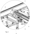
- each cross transport leg 34 is provided with one cross transport loop 40, preferably a chain.
- the cross transport loop 40 or chain may be integrated within the cross transport leg 34, as is shown in Fig. 4 , and may be driven by a motor 50.
- the drag-dogs 42 may be pneumatically controlled to switch between their retracted and protruding positions. This means they can be operated automatically.
- the profile end detection system provides means to automatically determine the longitudinal position of the first end 20 of the profile 24.
- An advantage of automatically determining said position is that a signal resulting from the profile end detection system can be further used to automatically move and position the measuring truck 18.
- Said profile end detection system may comprise detection systems which are known in the art. For example a laser-detector assembly determining whether there is a part of the profile between the laser and the detector.
- Another example of a profile end detection system could be a camera and image recognition software, wherein the image recognition software would determine the position of the profile 24 based on an image taken by the camera.
- the control system enables an automated infeed from the infeed cross transport assembly 12 to the infeed conveyor 16 and an optimal positioning of the measuring truck 18, whereby the amount of movement of the measuring truck 18 is minimized by taking into account the lengths of the profiles 24 which are to be positioned on the infeed conveyor 16.
- the control system may be part of the profile infeed assembly, or it may be implemented in a separate computer or IC.
- the control system may be dedicated hardware, implemented with dedicated software. Regardless of implementation the control system may control the movement of the measuring truck 18 such that the infeed time, i.e. the amount of time it takes for the profile 24 to be moved from the infeed cross transport assembly 12 to the working machine, is minimised.
- the roller conveyor may be a driven roller conveyor comprising powered rollers which may transport the profile 24 to the working machine.
- the roller conveyor may be a passive roller conveyor comprising non-powered rollers, in which case the measuring truck 18 is embodied as a gripper truck which may push the profile 24 to the working machine.
- the infeed conveyor 16 may further comprise a rail 48 on which the measuring truck 18 is moveably attached.
- the rail 48 is configured to allow the measuring truck 18 to move in the longitudinal direction of the infeed conveyor assembly 14.
- For movement of the measuring truck 18 it may be provided with a pinion which is driven by a motor and which is configured to engage a rack in the rail 48.
- the cross transport plane 38 can buffer said profiles 24 and thereby ensuring a constant supply of said profiles 24 to the infeed conveyor 16 and subsequently the working machine. In this way no time is wasted in waiting for the arrival of the profile 24.
- the invention furthermore relates to a profile processing assembly comprising a working machine, and the profile infeed assembly 10 according to the invention.
Landscapes
- Engineering & Computer Science (AREA)
- Mechanical Engineering (AREA)
- Physics & Mathematics (AREA)
- Optics & Photonics (AREA)
- Control Of Conveyors (AREA)
Claims (13)
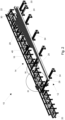
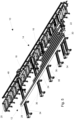
- Verfahren zum Bearbeiten von Profilen (24) in einer Profilbearbeitungsbaugruppe, wobei sich jedes Profil (24) entlang einer Profillängsachse (26) erstreckt und ein erstes Ende (28) und ein gegenüberliegendes zweites Ende (30) aufweist, wobei die Profilbearbeitungsbaugruppe aufweist:- eine Bearbeitungsmaschine; und- eine Profilzufuhrbaugruppe (10) zum Transportieren der Profile (24) in Richtung der Bearbeitungsmaschine, wobei die Profilzufuhrbaugruppe (10) aufweist:dadurch gekennzeichnet, dass• eine Zufuhrquertransportbaugruppe (12) zum Zuführen der Profile (24) in einer Querrichtung senkrecht zu den Profillängsachsen (26) der Profile (24); und• eine Zufuhrförderbaugruppe (14) zum Zuführen der Profile (24) in einer Längsrichtung parallel zu den Profillängsachsen (26) der Profile (24), wobei die Zufuhrförderbaugruppe (14) einen Zufuhrförderer (16) und einen Messwagen (18) aufweist, wobei der Zufuhrförderer (16) einen Rollenförderer zum Tragen des Profils (24) aufweist, das von der Zufuhrquertransportbaugruppe (12) aufgenommen wurde, wobei der Zufuhrförderer (16) ein erstes, von der Bearbeitungsmaschine entferntes Ende (20) und ein zweites, an die Bearbeitungsmaschine angrenzendes Ende (22) aufweist,wobei die Zufuhrquertransportbaugruppe (12) eingerichtet ist, um einzelne Profile (24) an die Zufuhrförderbaugruppe (14) zu liefern, und wobei die Zufuhrförderbaugruppe (14) eingerichtet ist, um einzelne Profile (24) an die Bearbeitungsmaschine zu liefern, wobei der Messwagen (18) an einem Profil (24) am ersten, der Bearbeitungsmaschine abgewandten Ende (28) des Profils (24) angreift und konfiguriert ist, um das Profil (24) entlang seiner Profillängsachse (26) über den Zufuhrförderer (16) zur Bearbeitungsmaschine zu führen,
der Messwagen (18) über eine Anzahl von Ruhepositionen (32) entlang der Länge des Zufuhrförderers (16) verfügt;
wobei das Verfahren umfasst:- Bestimmen der Längsposition des ersten Endes (28) eines Profils (24), das von der Bearbeitungsmaschine abgewandt ist, für jedes Profil (24), das durch die Zufuhrquertransportbaugruppe (12) der Zufuhrförderbaugruppe (14) zugeführt werden soll;- Bewegen des Messwagens (18) zu einer optimalen Ruheposition (32) der Anzahl von Ruhepositionen (32), wobei die optimale Ruheposition (32) die Ruheposition (32) zwischen dem ersten Ende (20) des Zufuhrförderers (16) und dem ersten Ende (28) des Profils (24) ist und diejenige Ruheposition (32) ist, die dem ersten Ende (28) des Profils (24) am nächsten ist;- Transportieren des Profils (24) von der Zufuhrquertransportbaugruppe (12) zur Zufuhrförderbaugruppe (14); und- Angreifen an dem ersten Ende (28) des Profils (24) mit dem Messwagen (18) zum Transportieren des Profils (24) entlang seiner Profillängsachse (26) zur Bearbeitungsmaschine. - Verfahren nach Anspruch 1, wobei die Zufuhrquertransportbaugruppe (12) aufweist:- eine Vielzahl von beabstandeten Quertransportstützen (34), die sich senkrecht zur Längsrichtung des Zufuhrförderers (16) erstrecken, wobei die Oberseiten (36) der Quertransportstützen (34) eine Quertransportebene (38) bilden, die im Betrieb das Profil (24) trägt; und- mindestens zwei Quertransportschleifen (40), die sich unterhalb der Quertransportebene (38) erstrecken und eine Vielzahl von einziehbaren Mitnehmern (42) aufweisen,wobei jeder der Mitnehmer (42) eine vorspringende Position hat, in der er über die Quertransportebene (38) hinausragt und im Betrieb am Profil (24) angreift, und wobei jeder der Mitnehmer (42) eine eingezogene Position hat, in der er unterhalb der Quertransportebene (38) bleibt,wobei die Mitnehmer (42) in der vorspringenden Position im Betrieb das Profil (24) von der Zufuhrquertransportbaugruppe (12) in Richtung der Zufuhrförderbaugruppe (14) bewegen.
- Verfahren nach Anspruch 2, wobei die Quertransportebene (38) mehrere Profile (24) trägt und wobei die Mitnehmer (42) im Betrieb alle Profile (24) entlang der Quertransportebene (38) in Richtung der Zufuhrförderbaugruppe (14) bewegen.
- Verfahren nach einem der vorhergehenden Ansprüche, wobei die Profilzufuhrbaugruppe (10) ein Profilendeerkennungssystem aufweist, wobei das Profilendeerkennungssystem den Schritt des Bestimmens der Längsposition des ersten Endes (28) des Profils (24) durchführt, das anschließend dem Zufuhrförderer (16) zugeführt werden soll.
- Verfahren nach Anspruch 4, wobei das Profilendeerkennungssystem eine Reihe von Fotozellen (44) aufweist, die neben dem Zufuhrförderer (16) angeordnet sind, wobei die Reihe von Fotozellen (44) in einer Längsrichtung des Zufuhrförderers (16) voneinander beabstandet sind und wobei jede Fotozelle (44) das Vorhandensein oder Nichtvorhandensein des Profils (24) an ihrer Position anzeigt.
- Verfahren nach Anspruch 5, wobei die optimale Ruheposition die Ruheposition (32) ist, die sich zwischen dem ersten Ende (20) des Zufuhrförderers (16) und einer ersten nicht belegten Fotozelle (44) befindet, die anzeigt, dass an ihrer Position kein Profil (24) vorhanden ist, und die die Ruheposition (32) ist, die der ersten nicht belegten Fotozelle (44) am nächsten ist, wobei die erste nicht belegte Fotozelle, die anzeigt, dass an ihrer Position kein Profil vorhanden ist, sich zwischen dem ersten Ende (20) des Zufuhrförderers (16) und einer belegten Fotozelle (44) befindet, die anzeigt, dass an ihrer Position ein Profil (24) vorhanden ist, und die die nicht belegte Fotozelle (44) ist, die der belegten Fotozelle (44) am nächsten ist.
- Verfahren nach einem der vorhergehenden Ansprüche, wobei die Profilzufuhrbaugruppe (10) ferner ein Steuersystem aufweist, das im Betrieb den Schritt des Bewegens des Messwagens (18) in die optimale Ruheposition durchführt.
- Verfahren nach Anspruch 7 in Abhängigkeit von Anspruch 4, wobei das Steuersystem ein Signal vom Profilendeerkennungssystem, das die Längsposition des ersten Endes (28) des Profils (24) anzeigt, als Eingangssignal verwendet und ein Steuersignal zum Bewegen des Messwagens (18) in die optimale Ruheposition erzeugt.
- Profilzufuhrbaugruppe (10) zum Transportieren von Profilen (24) zu einer Bearbeitungsmaschine, wobei die Profilzufuhrbaugruppe (10) aufweist:- eine Zufuhrquertransportbaugruppe (12) zum Zuführen von Profilen (24) in einer Querrichtung senkrecht zu den Profillängsachsen (26) der Profile (24); und- eine Zufuhrförderbaugruppe (14) zum Zuführen der Profile (24) in einer Längsrichtung parallel zu den Profillängsachsen (26) der Profile (24), wobei die Zufuhrquertransportbaugruppe (12) eingerichtet ist, um einzelne Profile (24) an die Zufuhrförderbaugruppe (14) zu liefern, und wobei die Zufuhrförderbaugruppe (14) eingerichtet ist, um einzelne Profile (24) an die Bearbeitungsmaschine zu liefern,wobei die Zufuhrförderbaugruppe (14) aufweist:• einen Zufuhrförderer (16), der einen Rollenförderer zum Tragen des Profils (24) aufweist, das von der Zufuhrquertransportbaugruppe (12) aufgenommen wurde, wobei der Zufuhrförderer ein erstes, von der Bearbeitungsmaschine entferntes Ende (20) und ein zweites, an die Bearbeitungsmaschine angrenzendes Ende (22) aufweist; und• einen Messwagen (18), wobei der Messwagen (18) an einem Profil (24) an einem ersten, der Bearbeitungsmaschine abgewandten Ende (28) des Profils (24) angreift und konfiguriert ist, um das Profil (24) entlang seiner Profillängsachse (26) über den Zufuhrförderer (16) zur Bearbeitungsmaschine zu führen,
dadurch gekennzeichnet, dass• der Messwagen (18) über eine Anzahl von Ruhepositionen (32) entlang der Länge des Zufuhrförderers (16) verfügt;wobei die Profilzufuhrbaugruppe (10) ein Profilendeerkennungssystem aufweist, das konfiguriert ist, um die Längsposition des ersten Endes (28) des Profils (24) zu bestimmen, das dem Zufuhrförderer (16) zugeführt werden soll,wobei die Profilzufuhrbaugruppe (10) ferner ein Steuersystem aufweist, das konfiguriert ist, um ein Signal von dem Profilendeerkennungssystem, das die Längsposition des ersten Endes (28) des Profils (24) anzeigt, zu verwenden, um die Bewegung des Messwagens (18) zu einer optimalen Ruheposition zu steuern, die die Ruheposition (32) der Anzahl von Ruhepositionen (32) ist, die zwischen dem ersten Ende (20) des Zufuhrförderers (16) und dem ersten Ende (28) des Profils (24) ist und diejenige Ruheposition (32) ist, die dem ersten Ende (28) des Profils (24) am nächsten ist. - Profilzufuhrbaugruppe nach Anspruch 9, wobei die Zufuhrquertransportbaugruppe (12) aufweist:- eine Vielzahl von beabstandeten Quertransportstützen (34), die sich senkrecht zur Längsrichtung des Zufuhrförderers (16) erstrecken, wobei die Oberseiten (36) der Quertransportstützen (34) eine Quertransportebene (38) bilden, die im Betrieb das Profil (24) trägt; und- mindestens zwei Quertransportschleifen (40) (z. B. ein Band oder eine Kette), die sich unterhalb der Quertransportebene (38) erstrecken und eine Vielzahl von einziehbaren Mitnehmern (42) (Nocken) aufweisen, wobei jeder der Mitnehmer (42) eine vorspringende Position hat, in der er über die Quertransportebene (38) hinausragt und im Betrieb am Profil (24) angreift, und wobei jeder der Mitnehmer (42) eine eingezogene Position hat, in der er unterhalb der Quertransportebene (38) bleibt,wobei die Mitnehmer (42) in der vorspringenden Position konfiguriert sind, um das Profil (24) von der Zufuhrquertransportbaugruppe (12) in Richtung der Zufuhrförderbaugruppe (14) zu bewegen.
- Profilzufuhrbaugruppe nach Anspruch 10, wobei die Quertransportebene (38) konfiguriert ist, um eine Vielzahl von Profilen (24) zu tragen, und wobei die Mitnehmer (42) konfiguriert sind, um alle Profile (24) gleichzeitig entlang der Quertransportebene (38) in Richtung der Zufuhrförderbaugruppe (14) zu bewegen.
- Profilzufuhrbaugruppe nach einem der Ansprüche 9 bis 11, wobei das Profilendeerkennungssystem eine Reihe von Fotozellen (44) aufweist, die neben dem Zufuhrförderer (16) angeordnet sind, wobei die Reihe von Fotozellen (44) in der Längsrichtung des Zufuhrförderers (16) voneinander beabstandet sind und wobei jede Fotozelle (44) konfiguriert ist, um das Vorhandensein oder Nichtvorhandensein des Profils (24) an ihrer Position anzuzeigen, wobei das Steuersystem konfiguriert ist, um den Messwagen (18) in die optimale Ruheposition zu bringen, wobei die optimale Ruheposition die Ruheposition (32) ist, die sich zwischen dem ersten Ende (20) des Zufuhrförderers (16) und einer ersten nicht belegten Fotozelle (44) befindet, die anzeigt, dass an ihrer Position kein Profil vorhanden ist, und die die Ruheposition (32) ist, die der ersten nicht belegten Fotozelle (44) am nächsten ist, wobei die erste nicht belegte Fotozelle (44), die anzeigt, dass an ihrer Position kein Profil (44) vorhanden ist, sich zwischen dem ersten Ende (20) des Zufuhrförderers (16) und einer ersten belegten Fotozelle (44) befindet, die anzeigt, dass an ihrer Position ein Profil (24) vorhanden ist, und die die nicht belegte Fotozelle (44) ist, die der ersten belegten Fotozelle (44) am nächsten ist.
- Profilbearbeitungsbaugruppe mit,- einer Bearbeitungsmaschine; und- einer Profilzufuhrbaugruppe (10) nach einem der Ansprüche 9 bis 11.
Applications Claiming Priority (2)
| Application Number | Priority Date | Filing Date | Title |
|---|---|---|---|
| NL2022698A NL2022698B1 (en) | 2019-03-08 | 2019-03-08 | A method of processing profiles in a profile processing assembly and a profile infeed assembly for transporting profiles towards a working machine |
| PCT/NL2020/050150 WO2020185071A1 (en) | 2019-03-08 | 2020-03-06 | A method of processing profiles in a profile processing assembly and a profile infeed assembly for transporting profiles towards a working machine |
Publications (3)
| Publication Number | Publication Date |
|---|---|
| EP3934844A1 EP3934844A1 (de) | 2022-01-12 |
| EP3934844B1 true EP3934844B1 (de) | 2024-07-03 |
| EP3934844C0 EP3934844C0 (de) | 2024-07-03 |
Family
ID=66286898
Family Applications (1)
| Application Number | Title | Priority Date | Filing Date |
|---|---|---|---|
| EP20712703.6A Active EP3934844B1 (de) | 2019-03-08 | 2020-03-06 | Verfahren zum verarbeiten von profilen in einer profilverarbeitungsanordnung und profilzuführanordnung zum transportieren von profilen zu einer arbeitsmaschine |
Country Status (4)
| Country | Link |
|---|---|
| US (1) | US12275112B2 (de) |
| EP (1) | EP3934844B1 (de) |
| NL (1) | NL2022698B1 (de) |
| WO (1) | WO2020185071A1 (de) |
Families Citing this family (5)
| Publication number | Priority date | Publication date | Assignee | Title |
|---|---|---|---|---|
| NL2028614B1 (en) * | 2021-07-02 | 2023-01-10 | Voortman Steel Machinery Holding B V | Gripper truck assembly, machining system, and method of moving a workpiece with respect to a machining station |
| NL2033499B1 (en) * | 2022-11-10 | 2024-05-28 | Voortman Steel Machinery Holding B V | Machining systems and methods |
| NL2033500B1 (en) * | 2022-11-10 | 2024-05-28 | Voortman Steel Machinery Holding B V | Machining systems and methods |
| NL2034119B1 (en) | 2023-02-09 | 2024-08-29 | Voortman Steel Machinery Holding B V | Fabrication assembly and method of automated metal fabrication |
| PL444908A1 (pl) * | 2023-05-16 | 2024-11-18 | Mobus Spółka Z Ograniczoną Odpowiedzialnością | System transportu technologicznego, realizowany w procesie wytwarzania konstrukcji stalowych, w obszarach ich śrutowania oraz malowania |
Family Cites Families (4)
| Publication number | Priority date | Publication date | Assignee | Title |
|---|---|---|---|---|
| SE508479C2 (sv) * | 1993-04-07 | 1998-10-12 | Renholmens Mek Verkstad Ab | Anordning vid bedömningsstation vid justerverk |
| DE69707852D1 (de) * | 1997-07-18 | 2001-12-06 | Vn Sa Moutier | Stangenzuführvorrichtung für eine Werkzeugmaschine, insbesondere einen Drehautomaten |
| DE50307177D1 (de) * | 2003-09-19 | 2007-06-14 | Trumpf Werkzeugmaschinen Gmbh | Zuführvorrichtung für stangen- oder stabartige Werkstücke sowie maschinelle Anordnung mit einer derartigen Zuführvorrichtung |
| ATE552943T1 (de) * | 2008-02-15 | 2012-04-15 | Me C Al S P A | Vorrichtung zum bewegen von zu bearbeitenden profilen |
-
2019
- 2019-03-08 NL NL2022698A patent/NL2022698B1/en active
-
2020
- 2020-03-06 US US17/431,958 patent/US12275112B2/en active Active
- 2020-03-06 WO PCT/NL2020/050150 patent/WO2020185071A1/en not_active Ceased
- 2020-03-06 EP EP20712703.6A patent/EP3934844B1/de active Active
Also Published As
| Publication number | Publication date |
|---|---|
| US20220168859A1 (en) | 2022-06-02 |
| EP3934844C0 (de) | 2024-07-03 |
| EP3934844A1 (de) | 2022-01-12 |
| WO2020185071A1 (en) | 2020-09-17 |
| NL2022698B1 (en) | 2020-09-17 |
| US12275112B2 (en) | 2025-04-15 |
Similar Documents
| Publication | Publication Date | Title |
|---|---|---|
| EP3934844B1 (de) | Verfahren zum verarbeiten von profilen in einer profilverarbeitungsanordnung und profilzuführanordnung zum transportieren von profilen zu einer arbeitsmaschine | |
| US10023404B2 (en) | Workpiece handling systems and related devices and methods | |
| US6810784B1 (en) | Glass workpiece transporting and locating system | |
| JP2866778B2 (ja) | レーザ加工装置 | |
| CN109226438B (zh) | 一种拉轨机出料送料机械手 | |
| US6702096B2 (en) | Intelligent deck apparatus and method for positioning workpieces in preparation for processing | |
| US5454466A (en) | Accumulating conveyor | |
| KR100974864B1 (ko) | 플라즈마 컷팅 장치로 컷팅 대상을 자동으로 공급하는 자동 공급장치 | |
| CN210677677U (zh) | 一种精密零部件的自动装夹装置 | |
| CN115159076B (zh) | 用于轴棒的自动理料机 | |
| CN217070591U (zh) | 一种发电机转子轴直纹自动加工装置 | |
| CN118405461A (zh) | 第二输送装置及pcb板输送系统 | |
| JPH0961104A (ja) | ワークの機種検出装置 | |
| CN117157163A (zh) | 工件输送装置、板材加工设备和用于运行工件输送装置的方法 | |
| CN115106798A (zh) | 铝合金型材加工工艺及其设备 | |
| US4708582A (en) | Method for feeding a work | |
| JP4841453B2 (ja) | 木材等の加工機および加工方法 | |
| CN219884972U (zh) | 引导机构、输送装置以及移料机 | |
| JPH04354660A (ja) | バイパス経路を有するトランスファマシン | |
| CN214002985U (zh) | 一种自动化生产结构的传送组件 | |
| CN113001014B (zh) | 一种烟弹管商品码防伪打标生产线及其加工方法 | |
| JP2863341B2 (ja) | 板材の切断方法 | |
| JP5855962B2 (ja) | 加工システム | |
| JP4390496B2 (ja) | 切断機に対する素材供給方法および装置 | |
| CZ148996A3 (en) | Device for working wood workpieces in their longitudinal direction |
Legal Events
| Date | Code | Title | Description |
|---|---|---|---|
| STAA | Information on the status of an ep patent application or granted ep patent |
Free format text: STATUS: UNKNOWN |
|
| STAA | Information on the status of an ep patent application or granted ep patent |
Free format text: STATUS: THE INTERNATIONAL PUBLICATION HAS BEEN MADE |
|
| PUAI | Public reference made under article 153(3) epc to a published international application that has entered the european phase |
Free format text: ORIGINAL CODE: 0009012 |
|
| STAA | Information on the status of an ep patent application or granted ep patent |
Free format text: STATUS: REQUEST FOR EXAMINATION WAS MADE |
|
| 17P | Request for examination filed |
Effective date: 20210915 |
|
| AK | Designated contracting states |
Kind code of ref document: A1 Designated state(s): AL AT BE BG CH CY CZ DE DK EE ES FI FR GB GR HR HU IE IS IT LI LT LU LV MC MK MT NL NO PL PT RO RS SE SI SK SM TR |
|
| DAV | Request for validation of the european patent (deleted) | ||
| DAX | Request for extension of the european patent (deleted) | ||
| GRAP | Despatch of communication of intention to grant a patent |
Free format text: ORIGINAL CODE: EPIDOSNIGR1 |
|
| STAA | Information on the status of an ep patent application or granted ep patent |
Free format text: STATUS: GRANT OF PATENT IS INTENDED |
|
| INTG | Intention to grant announced |
Effective date: 20240125 |
|
| GRAS | Grant fee paid |
Free format text: ORIGINAL CODE: EPIDOSNIGR3 |
|
| GRAA | (expected) grant |
Free format text: ORIGINAL CODE: 0009210 |
|
| STAA | Information on the status of an ep patent application or granted ep patent |
Free format text: STATUS: THE PATENT HAS BEEN GRANTED |
|
| AK | Designated contracting states |
Kind code of ref document: B1 Designated state(s): AL AT BE BG CH CY CZ DE DK EE ES FI FR GB GR HR HU IE IS IT LI LT LU LV MC MK MT NL NO PL PT RO RS SE SI SK SM TR |
|
| REG | Reference to a national code |
Ref country code: CH Ref legal event code: EP |
|
| REG | Reference to a national code |
Ref country code: DE Ref legal event code: R096 Ref document number: 602020033290 Country of ref document: DE |
|
| U01 | Request for unitary effect filed |
Effective date: 20240805 |
|
| U07 | Unitary effect registered |
Designated state(s): AT BE BG DE DK EE FI FR IT LT LU LV MT NL PT RO SE SI Effective date: 20240902 |
|
| PG25 | Lapsed in a contracting state [announced via postgrant information from national office to epo] |
Ref country code: NO Free format text: LAPSE BECAUSE OF FAILURE TO SUBMIT A TRANSLATION OF THE DESCRIPTION OR TO PAY THE FEE WITHIN THE PRESCRIBED TIME-LIMIT Effective date: 20241003 |
|
| PG25 | Lapsed in a contracting state [announced via postgrant information from national office to epo] |
Ref country code: GR Free format text: LAPSE BECAUSE OF FAILURE TO SUBMIT A TRANSLATION OF THE DESCRIPTION OR TO PAY THE FEE WITHIN THE PRESCRIBED TIME-LIMIT Effective date: 20241004 Ref country code: PL Free format text: LAPSE BECAUSE OF FAILURE TO SUBMIT A TRANSLATION OF THE DESCRIPTION OR TO PAY THE FEE WITHIN THE PRESCRIBED TIME-LIMIT Effective date: 20240703 |
|
| PG25 | Lapsed in a contracting state [announced via postgrant information from national office to epo] |
Ref country code: IS Free format text: LAPSE BECAUSE OF FAILURE TO SUBMIT A TRANSLATION OF THE DESCRIPTION OR TO PAY THE FEE WITHIN THE PRESCRIBED TIME-LIMIT Effective date: 20241103 |
|
| PG25 | Lapsed in a contracting state [announced via postgrant information from national office to epo] |
Ref country code: HR Free format text: LAPSE BECAUSE OF FAILURE TO SUBMIT A TRANSLATION OF THE DESCRIPTION OR TO PAY THE FEE WITHIN THE PRESCRIBED TIME-LIMIT Effective date: 20240703 Ref country code: CZ Free format text: LAPSE BECAUSE OF FAILURE TO SUBMIT A TRANSLATION OF THE DESCRIPTION OR TO PAY THE FEE WITHIN THE PRESCRIBED TIME-LIMIT Effective date: 20240703 |
|
| PG25 | Lapsed in a contracting state [announced via postgrant information from national office to epo] |
Ref country code: RS Free format text: LAPSE BECAUSE OF FAILURE TO SUBMIT A TRANSLATION OF THE DESCRIPTION OR TO PAY THE FEE WITHIN THE PRESCRIBED TIME-LIMIT Effective date: 20241003 Ref country code: ES Free format text: LAPSE BECAUSE OF FAILURE TO SUBMIT A TRANSLATION OF THE DESCRIPTION OR TO PAY THE FEE WITHIN THE PRESCRIBED TIME-LIMIT Effective date: 20240703 |
|
| PG25 | Lapsed in a contracting state [announced via postgrant information from national office to epo] |
Ref country code: RS Free format text: LAPSE BECAUSE OF FAILURE TO SUBMIT A TRANSLATION OF THE DESCRIPTION OR TO PAY THE FEE WITHIN THE PRESCRIBED TIME-LIMIT Effective date: 20241003 Ref country code: PL Free format text: LAPSE BECAUSE OF FAILURE TO SUBMIT A TRANSLATION OF THE DESCRIPTION OR TO PAY THE FEE WITHIN THE PRESCRIBED TIME-LIMIT Effective date: 20240703 Ref country code: NO Free format text: LAPSE BECAUSE OF FAILURE TO SUBMIT A TRANSLATION OF THE DESCRIPTION OR TO PAY THE FEE WITHIN THE PRESCRIBED TIME-LIMIT Effective date: 20241003 Ref country code: IS Free format text: LAPSE BECAUSE OF FAILURE TO SUBMIT A TRANSLATION OF THE DESCRIPTION OR TO PAY THE FEE WITHIN THE PRESCRIBED TIME-LIMIT Effective date: 20241103 Ref country code: HR Free format text: LAPSE BECAUSE OF FAILURE TO SUBMIT A TRANSLATION OF THE DESCRIPTION OR TO PAY THE FEE WITHIN THE PRESCRIBED TIME-LIMIT Effective date: 20240703 Ref country code: GR Free format text: LAPSE BECAUSE OF FAILURE TO SUBMIT A TRANSLATION OF THE DESCRIPTION OR TO PAY THE FEE WITHIN THE PRESCRIBED TIME-LIMIT Effective date: 20241004 Ref country code: ES Free format text: LAPSE BECAUSE OF FAILURE TO SUBMIT A TRANSLATION OF THE DESCRIPTION OR TO PAY THE FEE WITHIN THE PRESCRIBED TIME-LIMIT Effective date: 20240703 Ref country code: CZ Free format text: LAPSE BECAUSE OF FAILURE TO SUBMIT A TRANSLATION OF THE DESCRIPTION OR TO PAY THE FEE WITHIN THE PRESCRIBED TIME-LIMIT Effective date: 20240703 |
|
| U20 | Renewal fee for the european patent with unitary effect paid |
Year of fee payment: 6 Effective date: 20250304 |
|
| PG25 | Lapsed in a contracting state [announced via postgrant information from national office to epo] |
Ref country code: SM Free format text: LAPSE BECAUSE OF FAILURE TO SUBMIT A TRANSLATION OF THE DESCRIPTION OR TO PAY THE FEE WITHIN THE PRESCRIBED TIME-LIMIT Effective date: 20240703 |
|
| PG25 | Lapsed in a contracting state [announced via postgrant information from national office to epo] |
Ref country code: SK Free format text: LAPSE BECAUSE OF FAILURE TO SUBMIT A TRANSLATION OF THE DESCRIPTION OR TO PAY THE FEE WITHIN THE PRESCRIBED TIME-LIMIT Effective date: 20240703 |
|
| PLBE | No opposition filed within time limit |
Free format text: ORIGINAL CODE: 0009261 |
|
| STAA | Information on the status of an ep patent application or granted ep patent |
Free format text: STATUS: NO OPPOSITION FILED WITHIN TIME LIMIT |
|
| 26N | No opposition filed |
Effective date: 20250404 |
|
| PGFP | Annual fee paid to national office [announced via postgrant information from national office to epo] |
Ref country code: GB Payment date: 20250521 Year of fee payment: 6 |
|
| PGFP | Annual fee paid to national office [announced via postgrant information from national office to epo] |
Ref country code: IE Payment date: 20250521 Year of fee payment: 6 |
|
| PG25 | Lapsed in a contracting state [announced via postgrant information from national office to epo] |
Ref country code: MC Free format text: LAPSE BECAUSE OF FAILURE TO SUBMIT A TRANSLATION OF THE DESCRIPTION OR TO PAY THE FEE WITHIN THE PRESCRIBED TIME-LIMIT Effective date: 20240703 |
|
| REG | Reference to a national code |
Ref country code: CH Ref legal event code: H13 Free format text: ST27 STATUS EVENT CODE: U-0-0-H10-H13 (AS PROVIDED BY THE NATIONAL OFFICE) Effective date: 20251023 |