EP3932635A1 - Arbeitsgerät - Google Patents
Arbeitsgerät Download PDFInfo
- Publication number
- EP3932635A1 EP3932635A1 EP20183204.5A EP20183204A EP3932635A1 EP 3932635 A1 EP3932635 A1 EP 3932635A1 EP 20183204 A EP20183204 A EP 20183204A EP 3932635 A1 EP3932635 A1 EP 3932635A1
- Authority
- EP
- European Patent Office
- Prior art keywords
- stud bolt
- tool
- gpa
- tool according
- housing part
- Prior art date
- Legal status (The legal status is an assumption and is not a legal conclusion. Google has not performed a legal analysis and makes no representation as to the accuracy of the status listed.)
- Granted
Links
Images


Classifications
-
- B—PERFORMING OPERATIONS; TRANSPORTING
- B27—WORKING OR PRESERVING WOOD OR SIMILAR MATERIAL; NAILING OR STAPLING MACHINES IN GENERAL
- B27B—SAWS FOR WOOD OR SIMILAR MATERIAL; COMPONENTS OR ACCESSORIES THEREFOR
- B27B17/00—Chain saws; Equipment therefor
- B27B17/0033—Devices for attenuation of vibrations
-
- B—PERFORMING OPERATIONS; TRANSPORTING
- B23—MACHINE TOOLS; METAL-WORKING NOT OTHERWISE PROVIDED FOR
- B23D—PLANING; SLOTTING; SHEARING; BROACHING; SAWING; FILING; SCRAPING; LIKE OPERATIONS FOR WORKING METAL BY REMOVING MATERIAL, NOT OTHERWISE PROVIDED FOR
- B23D57/00—Sawing machines or sawing devices not covered by one of the preceding groups B23D45/00 - B23D55/00
- B23D57/02—Sawing machines or sawing devices not covered by one of the preceding groups B23D45/00 - B23D55/00 with chain saws
-
- B—PERFORMING OPERATIONS; TRANSPORTING
- B25—HAND TOOLS; PORTABLE POWER-DRIVEN TOOLS; MANIPULATORS
- B25F—COMBINATION OR MULTI-PURPOSE TOOLS NOT OTHERWISE PROVIDED FOR; DETAILS OR COMPONENTS OF PORTABLE POWER-DRIVEN TOOLS NOT PARTICULARLY RELATED TO THE OPERATIONS PERFORMED AND NOT OTHERWISE PROVIDED FOR
- B25F5/00—Details or components of portable power-driven tools not particularly related to the operations performed and not otherwise provided for
-
- F—MECHANICAL ENGINEERING; LIGHTING; HEATING; WEAPONS; BLASTING
- F16—ENGINEERING ELEMENTS AND UNITS; GENERAL MEASURES FOR PRODUCING AND MAINTAINING EFFECTIVE FUNCTIONING OF MACHINES OR INSTALLATIONS; THERMAL INSULATION IN GENERAL
- F16F—SPRINGS; SHOCK-ABSORBERS; MEANS FOR DAMPING VIBRATION
- F16F15/00—Suppression of vibrations in systems; Means or arrangements for avoiding or reducing out-of-balance forces, e.g. due to motion
- F16F15/02—Suppression of vibrations of non-rotating, e.g. reciprocating systems; Suppression of vibrations of rotating systems by use of members not moving with the rotating systems
- F16F15/04—Suppression of vibrations of non-rotating, e.g. reciprocating systems; Suppression of vibrations of rotating systems by use of members not moving with the rotating systems using elastic means
-
- F—MECHANICAL ENGINEERING; LIGHTING; HEATING; WEAPONS; BLASTING
- F16—ENGINEERING ELEMENTS AND UNITS; GENERAL MEASURES FOR PRODUCING AND MAINTAINING EFFECTIVE FUNCTIONING OF MACHINES OR INSTALLATIONS; THERMAL INSULATION IN GENERAL
- F16F—SPRINGS; SHOCK-ABSORBERS; MEANS FOR DAMPING VIBRATION
- F16F15/00—Suppression of vibrations in systems; Means or arrangements for avoiding or reducing out-of-balance forces, e.g. due to motion
- F16F15/02—Suppression of vibrations of non-rotating, e.g. reciprocating systems; Suppression of vibrations of rotating systems by use of members not moving with the rotating systems
- F16F15/04—Suppression of vibrations of non-rotating, e.g. reciprocating systems; Suppression of vibrations of rotating systems by use of members not moving with the rotating systems using elastic means
- F16F15/06—Suppression of vibrations of non-rotating, e.g. reciprocating systems; Suppression of vibrations of rotating systems by use of members not moving with the rotating systems using elastic means with metal springs
-
- F—MECHANICAL ENGINEERING; LIGHTING; HEATING; WEAPONS; BLASTING
- F16—ENGINEERING ELEMENTS AND UNITS; GENERAL MEASURES FOR PRODUCING AND MAINTAINING EFFECTIVE FUNCTIONING OF MACHINES OR INSTALLATIONS; THERMAL INSULATION IN GENERAL
- F16F—SPRINGS; SHOCK-ABSORBERS; MEANS FOR DAMPING VIBRATION
- F16F15/00—Suppression of vibrations in systems; Means or arrangements for avoiding or reducing out-of-balance forces, e.g. due to motion
- F16F15/02—Suppression of vibrations of non-rotating, e.g. reciprocating systems; Suppression of vibrations of rotating systems by use of members not moving with the rotating systems
- F16F15/04—Suppression of vibrations of non-rotating, e.g. reciprocating systems; Suppression of vibrations of rotating systems by use of members not moving with the rotating systems using elastic means
- F16F15/08—Suppression of vibrations of non-rotating, e.g. reciprocating systems; Suppression of vibrations of rotating systems by use of members not moving with the rotating systems using elastic means with rubber springs ; with springs made of rubber and metal
-
- A—HUMAN NECESSITIES
- A01—AGRICULTURE; FORESTRY; ANIMAL HUSBANDRY; HUNTING; TRAPPING; FISHING
- A01G—HORTICULTURE; CULTIVATION OF VEGETABLES, FLOWERS, RICE, FRUIT, VINES, HOPS OR SEAWEED; FORESTRY; WATERING
- A01G23/00—Forestry
- A01G23/02—Transplanting, uprooting, felling or delimbing trees
- A01G23/08—Felling trees
- A01G23/091—Sawing apparatus specially adapted for felling trees
-
- A—HUMAN NECESSITIES
- A01—AGRICULTURE; FORESTRY; ANIMAL HUSBANDRY; HUNTING; TRAPPING; FISHING
- A01G—HORTICULTURE; CULTIVATION OF VEGETABLES, FLOWERS, RICE, FRUIT, VINES, HOPS OR SEAWEED; FORESTRY; WATERING
- A01G3/00—Cutting implements specially adapted for horticultural purposes; Delimbing standing trees
- A01G3/08—Other tools for pruning, branching or delimbing standing trees
- A01G3/085—Motor-driven saws for pruning or branching
-
- B—PERFORMING OPERATIONS; TRANSPORTING
- B27—WORKING OR PRESERVING WOOD OR SIMILAR MATERIAL; NAILING OR STAPLING MACHINES IN GENERAL
- B27B—SAWS FOR WOOD OR SIMILAR MATERIAL; COMPONENTS OR ACCESSORIES THEREFOR
- B27B17/00—Chain saws; Equipment therefor
- B27B17/02—Chain saws equipped with guide bar
Definitions
- the invention relates to an implement according to the preamble of claim 1.
- a working device with a stud bolt is known to which a guide bar with a saw chain is attached as a tool.
- a silicone sleeve is arranged between the guide rail and the stud bolt.
- the stud bolt is fastened in a housing part of the implement.
- forces are transmitted from the guide rail to the stud bolt. These forces can damage the connection between the stud bolt and the housing part and, in extreme cases, even ensure that the stud bolt is released from the housing part.
- the sleeve made of silicone is provided. The sleeve wears out quickly during operation, with the damping effect of the sleeve being weakened or completely nullified. Further operation of the implement can then quickly lead to a destabilization of the connection between the stud bolt and the housing part.
- the invention is based on the object of developing a generic working device in such a way that low-wear and safe operation of the working device is possible.
- the transmission element is designed as a first element, and that the first element consists at least partially of a first material that has a modulus of elasticity of 1 GPa (1 ⁇ 10 9 N / m 2 ) to 80 GPa (80 ⁇ 10 9 N / m 2) N / m 2 ), or that the transmission element is designed as a second element and that the second element has a spring element and a free space for a spring travel of the spring element, the spring element being at least partially made of a second material greater than 80 GPa.
- the first element consists at least partially of a first material that has a modulus of elasticity of 1 GPa to 80 GPa, the first element wears only very little and at the same time sufficiently dampens the transverse forces transmitted from the tool to the stud bolt. As a result, the implement can be operated safely and with little wear. Damage to the connection between the stud bolt and the housing part due to the transverse forces is thus effectively prevented. This enables safe and low-wear operation of the implement. As a result, forces can be transmitted with minimal spring deflection even at high transmission frequencies.
- the second element has a spring element at least partially made of a second material with a modulus of elasticity of greater than 80 GPa and a free space for a spring deflection of the spring element, the second element can be made of low-wear material.
- the second element in particular the spring element, wears only to a very small extent and at the same time sufficiently dampens the transverse forces transmitted from the tool to the stud bolt.
- the implement can be operated safely and with little wear.
- the second element consists at least partially of a second material that has a modulus of elasticity greater than 80 GPa, the second element can be designed to be particularly wear-resistant and durable.
- the two variants according to the invention have the technical effect in common that the respective transmission elements achieve a good damping effect with little wear.
- the good wear behavior is achieved by materials with a modulus of elasticity of at least 1 GPa. Up to and including 80 GPa, the damping effect of the materials themselves is sufficient. From more than 80 GPa, the transmission element must also have the spring element and the free space for the spring deflection of the spring element in order to achieve a sufficient damping effect.
- the second element is advantageously designed in such a way that it has a resilient effect at least partially due to its shape when the transverse forces are transmitted. The second element is then also referred to as a shaped spring.
- the transmission element runs completely around the stud bolt with respect to the axial direction.
- the transmission element is advantageously arranged between the opening and the stud bolt.
- the transmission element is arranged with play on the stud bolt. This facilitates the assembly and disassembly of the implement.
- the transmission element is expediently attached to the tool. This enables the tool to be exchanged without the risk of losing the transmission element.
- the opening has an edge, and that the transmission element is fixed on the edge of the opening of the tool.
- the transmission element is permanently connected to the tool.
- the tool consists of a smaller number of individual components and can therefore be easily assembled and disassembled.
- the transmission element is attached to the stud bolt. This can prevent the transmission element from being lost when a tool is changed.
- the transmission element is securely attached to the stud bolt.
- the transmission element is exchangeably held on the stud bolt.
- the transmission element can be adapted to the changed situation by exchanging the transmission element for a transmission element with a different modulus of elasticity. If the transmission element is worn out after a long period of use, the exchangeability means that the worn transmission element can be exchanged for a new transmission element in a simple manner.
- the transmission element is advantageously a sleeve.
- the sleeve expediently has essentially the shape of a hollow cylinder.
- An essentially hollow cylindrical sleeve can also be a slotted sleeve.
- the first element expediently consists entirely of the first material. This enables the first element to be produced in a simple manner.
- the first material is advantageously plastic.
- the first material is not an elastomer.
- the first material is light metal.
- the first material can be aluminum.
- the first material can also be an aluminum alloy.
- the second element advantageously consists entirely of the second material.
- the spring element of the second element is arranged between the free space of the second element and the stud bolt.
- a free space width of the free space of the second element, measured radially to the longitudinal axis of the stud bolt and perpendicular to a longitudinal center axis of the tool is expediently at least 10%, in particular at least 20% of a spring width of the spring element measured radially to the longitudinal axis of the stud bolt and perpendicular to the longitudinal center axis of the tool.
- a shaped spring can thereby be formed.
- the second element can be designed in such a way that the damping effect of the second element is sufficient.
- the housing part is at least partially made of light metal, in particular aluminum. This makes the tool light and easy to use. It can also be provided that the housing part consists of an aluminum or a magnesium alloy.
- the tool is free of rotational symmetry with respect to the longitudinal axis of the stud bolt.
- the tool advantageously has no rotational symmetry with respect to the longitudinal axis of the stud bolt.
- at least a part of the tool is immobile relative to the housing part when the working device is in operation.
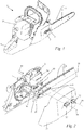
- Fig. 1 shows a hand-held tool 1.
- the hand-held tool 1 is a motorized chain saw.
- the implement 1 has a handle 9 and a guide rail 8 on which a saw chain 7 is guided in a circumferential manner.
- the handle 9 is arranged on a rear side of a housing 31 of the power chain saw.
- the guide rail 8 protrudes from the housing 31 on a front side of the housing 31 of the power chain saw.
- the guide bar 8 and the saw chain 7 together form a tool 4 of the implement 1.
- the tool 4 has an in Fig. 2
- the opening 5 is formed in the guide rail 8.
- At least one stud bolt 3 protrudes through the opening 5.
- a fastening element 32 screwed to the stud bolt 3 clamps the guide rail 8 against the housing 31.
- the fastening element 32 is a nut in the exemplary embodiment.
- the implement 1 has a housing part 2 which forms part of the housing 31.
- a motor (not shown) for driving the saw chain 7 is fixed to the housing part 2.
- the housing part 2 is part of a Motor housing on which the motor is arranged.
- the engine is advantageously an internal combustion engine, and the housing part 2 forms part of a crankcase of the internal combustion engine.
- the at least one stud bolt 3 protrudes from the housing part 2.
- two stud bolts 3 are provided.
- the stud bolt 3 extends along a longitudinal axis 49.
- the longitudinal axis 49 runs in the axial direction 50.
- the axial direction 50 extends from the housing part 2 in the direction of the guide rail 8.
- a stud bolt 3 is perpendicular to an in Fig. 4 illustrated bearing surface 33 of the housing part 2 is oriented.
- the guide rail 8 rests directly or indirectly on the support surface 33.
- a side plate 34 is usually placed on the support surface 33.
- the side plate 34 is then arranged between the guide rail 8 and the support surface 33.
- the guide rail 8 is then placed on the side plate 34.
- the side plate 34 has an opening with which it is plugged onto the stud bolt 3.
- the stud bolt 3 is made of steel.
- the stud bolt 3 consists of hardened steel.
- the housing part 2 is advantageously at least partially made of light metal, in particular a magnesium alloy. It can also be provided that the housing part consists of several different materials. In particular, the housing part 2 can form part of a crankcase of an internal combustion engine of the working device 1.
- the stud bolt 3 is exchangeable.
- the stud bolt 3 can be screwed out of the housing part 2, in particular from the support surface 33.
- the guide rail 8 has a rear end 35.
- the rear end 35 has the opening 5.
- the rear end 35 faces the handle 9.
- the tool 4 extends along a central longitudinal axis 48.
- the central longitudinal axis 48 is the central longitudinal axis of the guide rail 8.
- the central longitudinal axis 48 runs perpendicular to the longitudinal axis 49 of the stud 3.
- the guide rail 8 extends in a perpendicular plane to the longitudinal axis 49
- Fig. 2 is the opening 5 in the guide rail 8 to the rear end 35 of the guide rail 8 open. However, it can also be provided that the opening 5 is closed towards the rear end 35 of the guide rail 8. This is in the exemplary embodiments according to Figures 3 to 9 the case in which the opening 5 is designed as an elongated hole. As in Fig.
- the opening 5 penetrates the guide rail 8 in the axial direction 50 completely.
- the opening 5 of the guide rail 8 is advantageously arranged symmetrically with respect to a plane spanned by the longitudinal center axis 48 and the longitudinal axis 49.
- the opening 5 extends along the longitudinal center axis 48.
- the guide rail 8 is pushed with its opening 5 over the two stud bolts 3.
- the two stud bolts 3 are arranged one behind the other on the longitudinal center axis 48.
- the two stud bolts 3 can be designed the same per se. This applies to all exemplary embodiments. However, it can also be provided that the stud bolts 3 are designed differently.
- a collar for supporting the guide rail 8 is arranged on the stud bolts 3.
- the federal government 36 can as in the Figures 3 to 7 shown, be formed by a separate component. But it can also be provided that the collar 36 is an integral part of the stud 3, as in the embodiments according to the Figures 8 and 9 .
- the guide rail 8 rests against the periphery of the opening 5 on the collar 36.
- the guide rail can be displaced relative to the housing part 2 in the direction of its longitudinal center axis 48 when it rests on the stud bolts.
- the stud bolts 3 are guided through holes in a sprocket cover 37 of the implement 1.
- the sprocket cover 37 covers the opening 5 of the guide rail 8 at least partially.
- the guide rail 8 is arranged between the housing part 2 and the sprocket cover 37. By moving the guide bar 8 relative to the housing part 2, the saw chain 7 can be tensioned. 32 nuts are screwed onto the stud bolts 3 protruding from the sprocket cover 37 as fastening means.
- the guide rail 8 is on the housing part 2 attached.
- the saw chain 7 revolves around the guide bar 8 when the implement 1 is in operation.
- the saw chain 7 is guided by the guide bar 8.
- the guide rail 8 is immovable relative to the housing part 2.
- the tool 4 is free of rotational symmetry with respect to the longitudinal axis 49 of the stud bolt 3.
- the greatest distance between an outer edge of the tool 4 and the longitudinal axis 49 is a multiple of the smallest distance between an outer edge of the tool 4 and the longitudinal axis 49 Tool 4 to the longitudinal axis 49.
- the guide rail 8 can vibrate when the working device 1 is in operation. As a result of the vibrations or also when sawing with a motorized chain saw, forces are transmitted from the guide rail 8 to the stud bolt 3 and introduced into the housing part 2 by the stud bolt 3.
- the working device 1 has a transmission element.
- the transmission element serves to transmit transverse forces acting transversely to the axial direction 50 from the tool 4, in particular from the guide rail 8, to the stud bolt 3.
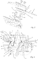
- the Figures 3 to 9 show different designs for a transmission element. Identical or similar parts are denoted by identical reference symbols.
- the transmission element is a first element 10.
- the embodiment according to Figures 5 and 6 shows the first element 10 in an alternative embodiment.
- the Figures 7 and 8 each show a further exemplary embodiment for a first element 10.
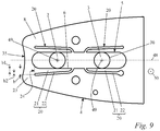
- the transmission element is designed as a second element 20.
- the first element 10 consists at least partially of a first material which has a modulus of elasticity of 1 GPa to 80 GPa.
- the second element 20 has a Spring element 21 and a free space 22 on ( Fig. 9 ).
- the spring element 21 consists at least partially of a second material with a modulus of elasticity of greater than 80 GPa.
- the free space 22 serves as a spring travel for the spring element 21.
- the second element 20 is designed such that it has a resilient effect at least partially due to its shape when the transverse forces are transmitted.
- the second element 20 is a shaped spring.
- the second element 20 can, as in FIG Fig. 9 shown, be formed integrally with the guide rail 8.
- the guide rail 8 forms in its contact point on the stud bolt 3 in this case a shaped spring for transferring the transverse forces from the guide rail 8 to the stud bolt 3.
- the second element 20 is a separate component between the guide rail 8 and the stud bolt 3 is arranged.
- the resilient effect of the second element 20 can then be implemented, for example, in that the second element 20 consists at least partially of a knitted wire mesh, not shown.
- the wire mesh can consist of steel, for example.
- the wire mesh can essentially have the shape of a hollow cylinder. Free spaces are formed between the wires of the knitted wire. A section of a wire forms the spring element.
- the transmission element has a spring element and a free space for the spring travel of the spring element and that the spring element consists at least partially of the first material with a modulus of elasticity of 1 GPa to 80 GPa, in particular from 60 GPa to 80 GPa. It can be provided that the transmission element is partly made of the first material with a modulus of elasticity of 1 GPa to 80 GPa, in particular from 60 GPa to 80 GPa, and also has a resilient effect at least partly due to its shape when the transverse forces are transmitted.
- the first element 10 shown is arranged between the stud bolt 3 and the tool 4.
- the first element 10 is arranged between the guide rail 8 and the stud bolt 3.
- the housing part 2 has a receptacle 38.
- the recording 38 is used for recording of the stud bolt 3.
- the receptacle 38 has an internal thread 39.
- the stud bolt 3 has an external thread 40 on its longitudinal end facing the housing part 2.
- the stud bolt 3 is screwed into the receptacle 38.
- the external thread 40 extends only over part of the longitudinal extent of the receptacle 38 in the axial direction 50.
- the stud bolt 3 protrudes from the receptacle 38 in the axial direction 50.
- the opening 5 has an edge 6.
- the edge 6 runs around in a closed manner around the axial direction 50.
- the first element 10 is arranged between the edge 6 of the opening 5 and the stud bolt 3.
- the first element 10 rests on the stud bolt 3.
- the first element 10 runs around the stud bolt 3.
- the transmission element runs completely around the stud bolt 3 with respect to the axial direction 50.
- the transmission element encloses the longitudinal axis 49 of the stud bolt 3. This applies both to the first element 10 and to the second element 20 in the form of a knitted wire.
- the transmission element is arranged between the opening 5 and the stud bolt 3.
- the transmission element is a sleeve.
- the second element 20 made of knitted wire can also be referred to as a sleeve.
- the sleeve essentially has the shape of a hollow cylinder. It can also be provided that the sleeve is slotted.
- a slotted sleeve also has essentially the shape of a hollow cylinder.
- a common transmission element can also be provided for the two adjacent stud bolts 3.
- the common transmission element then has two interconnected sleeves. The two sleeves can be connected to one another via a web. When viewed in the axial direction 50, this common transmission element is glasses-shaped.
- the stud bolt 3 has an element stop 45 in all exemplary embodiments.
- the element stop 45 serves as a stop for the transmission element in the direction opposite to the axial direction 50.
- the transmission element rests against the element stop 45.
- the element stop 45 secures the first element 10 against movement counter to the axial direction 50 in the direction of the housing part 2. This also applies to the second element 20, which is designed as a wire mesh.
- the element stop 45 advantageously runs completely around the stud bolt 3 with respect to the axial direction 50.
- the element stop 45 is formed by a projection 47 of the stud bolt 3.
- the projection 47 protrudes over a bolt base body 46 in the radial direction with respect to the longitudinal axis 49 of the stud bolt 3.
- the element stop 45 protrudes beyond the bolt base body 46 in the radial direction with respect to the longitudinal axis 49 of the stud bolt 3.
- the projection 47 forms a bolt stop 30 for the stud bolt 3 on the housing part 2.
- the projection 47 is used to rest on the housing part 2. Via the projection 47, transverse forces can be transmitted from the stud bolt 3 to the housing part 2 during operation of the implement 1.
- the first element 10 according to the exemplary embodiments according to Figures 3 to 7 is secured to the stud bolt 3 by a securing device 11.
- the securing device 11 comprises a threaded connection between the first element 10 and the stud bolt 3.
- the first element 10 is screwed onto the stud bolt 3.
- the stud bolt 3 has an external securing thread 41 on its longitudinal end protruding from the housing part 2 ( Fig. 4 ).
- the first element has an internal locking thread 42.
- the internal securing thread 42 corresponds to the external securing thread 41.
- the external securing thread 41 and the internal securing thread 42 together form the securing device 11 for securing the first element 10 on the stud bolt 3.
- the first element is secured against movement in the axial direction 50 on the stud bolt 3 during operation.
- the securing external thread 41 has a distance from the element stop 45, measured in the axial direction 50. The distance is greater than a height of the first element 10 measured in the axial direction 50. Because the external securing thread 41 only extends over part of the free end of the stud 3, the first element 10 can be screwed on to the external securing thread 41 and the internal securing thread 42 disengage. Due to the distance described, the first element 10 is then located directly on the element stop 45.
- Movement counter to the axial direction 50 is only possible if the first element 10 is manually reinserted with its internal securing thread 42 into the external securing thread 41 of the stud 3. In addition, the first element 10 and the stud bolt 3 must be rotated against each other in the opposite direction of rotation.
- the first element 10 has a double surface 12.
- An open-end wrench can act on the double flat 12 and in this way the first element 10 can be screwed onto the stud bolt 3 or unscrewed from the stud bolt 3.
- the securing device 11 is formed by a securing ring 43 and a groove 44 in the stud bolt 3.
- the groove 44 runs around the stud bolt 3 with respect to the axial direction 50.
- the groove 44 is a recess in the outer surface of the stud bolt 3.
- the groove 44 is a recess in the base body 46 of the stud bolt 3.
- the groove 44 is arranged with respect to the axial direction 50 on the side of the transmission element facing away from the housing part 2.
- the first element 10 is arranged between the groove 44 and the housing part 2.
- the locking ring 43 engages in the groove 44.
- the securing ring 43 protrudes from the groove 44 in the direction transverse to the axial direction 50.
- the locking ring 43 limits movement of the transmission element, in particular the first element 10 in the axial direction 50.
- the transmission element, in particular the first element 10 is secured against movement in the axial direction 50 relative to the stud bolt 3 in the direction away from the housing part 2.
- the second element 20 is secured in the form of a knitted wire by a securing device 11 with a securing ring 43 and a groove 44.
- a locking element can be provided.
- the latching element is an integral part of the first element 10.
- the latching element snaps into the groove 44 and thus permanently secures the first element 10 against movement in the axial direction 50 relative to the stud 3.
- the position of the first element 10 with respect to the axial direction 50 relative to the stud bolt 3 is limited to a certain area with respect to the longitudinal axis 49 of the stud bolt 3.
- the position of the first element 10 is determined such that the first element 10 extends at least over the entire width of the guide rail 8 measured in the axial direction 50. It can also be provided that the position of the second element 20 in the form of a knitted wire mesh is restricted and determined in an analogous manner.
- the transmission element is held on the stud bolt 3 in an exchangeable manner. This applies both to the first element 10 according to the exemplary embodiments according to FIG Figures 3 to 7 as well as for the second element 20, which is designed as a wire mesh.
- the first element 10 is in the exemplary embodiments according to Figures 3 to 7 with its inside at least partially on the stud bolt 3. There is advantageously a slight play between the first element 10 and the stud bolt 3.
- the first Element 10 rests on stud bolt 3 in the direction transverse to axial direction 50, in particular perpendicular to axial direction 50.
- the first element 10 rests on the edge 6 of the opening 5 in the direction transverse to the axial direction 50, in particular in the direction perpendicular to the axial direction 50. From the edge 6 of the opening 5, transverse forces can be transmitted from the tool 4, in particular from the guide rail 8, to the first element 10 via the first element 10. Transverse forces can be transmitted from the first element 10 to the stud bolt 3.
- the stud bolt 3 has a modulus of elasticity of 190 GPa to 230 GPa, in particular 210 GPa.
- the first element 10 consists at least partially of the first material, which has a modulus of elasticity of 1 GPa to 80 GPa. In the embodiments according to Figures 3 to 8 the first element 10 consists entirely of the first material. Due to the different modulus of elasticity of the first element 10 and the stud bolt 3, there is a large difference between the stiffnesses of the first element 10 and the stud bolt 3. With regard to the stiffnesses lies in the direction radially to the longitudinal axis 49 of the stud bolt 3 at the transition from the transmission element to the stud bolt 3 a leap in rigidity.
- the first material of the first element 10 has a modulus of elasticity of 1 GPa to 80 GPa.
- the first material of the first element 10 can be plastic or metal, in particular light metal.
- the light metal preferably contains aluminum.
- the light metal advantageously contains an aluminum alloy.
- the first material of the first element 10 is plastic, it advantageously has a modulus of elasticity of 1 GPa to 10 GPa.
- the first material of the first element 10 is not an elastomer.
- the plastic from which the first material of the first element 10 is made is advantageously polyetheretherketone (PEEK). It can also be provided that the first element 10 from the embodiment according to the Figures 3 to 8 has a modulus of elasticity of 1 GPa to 10 GPa and / or is made of plastic, in particular PEEK.
- the first material of the first element 10 is metal
- the first material of the first element 10 has a modulus of elasticity from 10 GPa to 80 GPa, in particular from 50 GPa to 80 GPa.
- the first material of the first element 10 can in particular be light metal.
- the metal advantageously contains aluminum.
- the metal preferably contains an aluminum alloy.
- the first element 10 can consist entirely of the first material. It can also be provided that the first element 10 from the embodiment according to the Figures 3 to 8 has a modulus of elasticity from 10 GPa to 80 GPa, in particular from 50 GPa to 80 GPa and / or is made of light metal, in particular of an aluminum alloy.
- the exemplary embodiments show a working device 1 comprising the tool 4, the housing part 2 and the stud bolt 3 screwed into the housing part 2 for fastening the tool 4 to the housing part 2, the stud bolt 3 protruding from the housing part 2 along the axial direction 50, with the tool 4 has the opening 5, the stud bolt 3 protruding at least partially into the opening 5, the working device 1 having the transmission element for the transmission of transverse forces acting transversely to the axial direction 50 from the tool 4 to the stud bolt 3, the transmission element from a group with a designed as a first element 10 transmission element and a transmission element designed as a second element 20 is selected, wherein the first element 10 consists at least partially of a first material that has a modulus of elasticity of 1 GPa to 80 GPa and wherein the second element 20 has a spring element 21 at least partially off a second material with a modulus of elasticity of greater than 80 GPa and a free space 22 for a spring deflection of the spring element 21.
- the stud bolt 3 has a bolt radius r in the area of the transmission element.
- the bolt radius r is in the embodiments according to Figures 3 to 9 more than 2.5 mm, in particular more than 2.8 mm, preferably more than 3.1 mm.
- the bolt radius r is less than 4 mm, in particular less than 3.7 mm, preferably less than 3.3 mm.
- the first element 10 has a maximum thickness d measured radially to the longitudinal axis 49 of the stud bolt 3. It can also be provided that the maximum thickness d is measured radially to the longitudinal axis 49 of the stud 3 and perpendicular to the longitudinal center axis 48. This is in the embodiments according to Figures 7 and 8 the case.
- the maximum thickness d is at least 30%, in particular at least 40%, preferably at least 50% of the bolt radius r of the stud 3.
- the maximum thickness d is in the exemplary embodiments according to FIG Figures 3 to 8 at least 1 mm, preferably at least 1.5 mm.
- the maximum thickness d is at most 100%, in particular at most 80%, preferably at most 60% of the bolt radius r.
- the maximum thickness d is in the exemplary embodiments according to Figures 3 to 7 at most 3 mm, in particular at most 2.5 mm, preferably at most 2 mm.
- the stated values also apply to the second element 20 in the form of a knitted wire.
- the first element 10 is designed as a sleeve.
- the first element 10 has a star-shaped outer contour counter to the axial direction 50.
- the first element 10 in execution according to Fig. 7 is screwed onto the stud 3.
- the threaded connection between the stud bolt 3 and the first element 10 is formed by the securing device 11.
- the first element 10 in execution Fig. 8 can also by any other of the embodiments according to the Figures 3 to 6 described securing devices 11 be secured against movement in the axial direction 50.
- the transmission element formed as the first element 10 is fixed on the tool 4.
- the first element 10 and the tool 4 are separate components.
- the first element 10 is fixed on the edge 6 of the opening 5 of the tool 4.
- the first element 10 is immovable with respect to the tool 4, at least in the direction of the longitudinal center axis 48.
- the first element 10 is advantageously molded onto the edge 6 of the opening 5.
- the first element 10 is thereby fixed in the axial direction 50.
- the first element 10 can also be designed as an insert part which is pressed into the opening 5 and thus also fixed in the axial direction 50.
- the first element 10 extends in the exemplary embodiment according to Fig. 8 Over the entire width of the guide rail 8 measured in the axial direction 50.
- the first element 10 completely covers the edge 6 of the opening 5.
- the first element 10 follows in the exemplary embodiment Fig. 8 with respect to the axial direction 50 completely around the longitudinal axis 49 of the stud bolt 3.
- the transmission element is designed as a second element 20.
- the second element 20 is part of the tool 4.
- the second element 20 is part of the guide rail 8.
- a slot in the guide rail 8 is provided in the guide rail 8, starting from the edge 6 of the opening 5.
- a free space 22 is formed through the slot.
- a spring element 21 is formed between the free space 22 and the opening 5 of the guide rail 8. The spring element 21 rests on the stud bolt 3.
- the second element 20 is formed by the spring element 21 and the free space 22.
- the free space 22 provides a spring travel for the spring element 21.
- the second element 20 is designed in such a way that it has a resilient effect when the transverse forces are transmitted due to its shape.
- the longitudinal center axis 48 of the tool 4 and the longitudinal axis 49 of the stud bolt 3 span a center plane.
- a maximum width b of the spring element 21 measured perpendicular to this central plane is selected such that the spring element 21 has a resilient effect.
- the free space 22 enables the spring element 21 to move in the direction transverse to the axial direction 50.
- forces in particular transverse forces, are resiliently transmitted from the guide rail 8 to the stud bolt 3.
- the second element 20 is a shaped spring.
- the maximum width b of the spring element 21 is measured along an imaginary line on the guide rail 8. This imaginary line with the maximum width b of the spring element 21 marks a separation point between the second element 20 and a base body 23 of the guide rail 8. A plane perpendicular to the longitudinal center axis 48 separates the spring element 21 from the base body 23.
- the second element 20 is arranged between the base body 23 and the stud bolt 3.
- the base body of the guide rails is formed by the entire guide rail 8.
- the first element 10 is arranged between the base body of the guide rail 8 and the stud bolt 3.
- the transmission element is arranged between the base body of the guide rail 8 and the stud bolt 3. This applies with regard to the direction transverse, in particular perpendicular, in particular radially to the axial direction 50.
- the spring element 21 of the second element 20 is arranged between the free space 22 of the second element 20 and the stud bolt 3.
- the spring element 21 is a tongue.
- the tongue extends from the base body 23 of the guide rail 8.
- the tongue extends essentially along the direction of the longitudinal center axis 48 of the guide rail 8.
- the spring element 21 has a longitudinal end 24 on. At the longitudinal end 24, the spring element 21 has the maximum width b.
- the spring element 21 is fixed with its longitudinal end 24 on the base body 23 of the guide rail 8.
- the spring element 21 is an integral part of the guide rail 8.
- the spring element 21 is made of the same material as the base body 23.
- the spring element 21 of the second element 20 has a spring width b1.
- the spring width b1 is measured radially to the longitudinal axis 49 of the stud bolt 3 and perpendicular to the longitudinal center axis 48 of the tool 4.
- the spring width b1 is measured perpendicular to the center plane at the level of the longitudinal axis 49 of the stud bolt 3.
- the free space 22 is arranged between the base body 23 and the spring element 21.
- the free space 22 is arranged between the base body 23 and the spring element 21 with respect to the radial direction of the longitudinal axis 49.
- the free space 22 of the second element 20 has a free space width b2.
- the free space width b2 is measured radially to the longitudinal axis 49 of the stud bolt 3 and perpendicular to the longitudinal center axis 48 of the tool 4.
- the free space width b2 is measured perpendicular to the center plane at the level of the longitudinal axis 49 of the stud bolt 3.
- the free space width b2 is measured between the spring element 21 and the base body 23.
- the free space width b2 is measured when the spring element 21 is in contact with the stud bolt 3.
- the free space width b2 is at least 10%, in particular at least 20% of the spring width b1. In the embodiment according to Fig. 9 the free space width b2 is at least 30% of the spring width b1.
- the free space width b2 is at least 10%, in particular at least 20% of the maximum width b. In the embodiment according to Fig. 9 the free space width b2 is at least 0.1 mm, in particular at least 0.5 mm. The free space width b2 is at most 70%, in particular at most 50%, preferably at most 40% of the maximum width b. The free space width b2 is at most 2 mm, in particular at most 1.5 mm.
- the second element 20 consists at least partially of a second material which has a modulus of elasticity of greater than 80 GPa.
- the spring element 21 consists at least partially of a second material which has a modulus of elasticity greater than 80 GPa. It can also be provided that the second element 20, in particular the spring element 21, consists at least partially of a material that has a modulus of elasticity of greater than 60 GPa.
- the spring element 21 has a modulus of elasticity of 200 GPa to 330 GPa, in particular from 280 GPa to 330 GPa, preferably from 290 GPa to 320 GPa.
- the second material is steel.
- the spring element 21 consists entirely of the second material.
- the base body 23 of the guide rail 8 consists of the second material.
- the guide rail 8 has a modulus of elasticity greater than 80 GPa. In the exemplary embodiments, the guide rail 8 has a modulus of elasticity from 200 GPa to 330 GPa, in particular from 280 GPa to 330 GPa.
- the guide rail 8 is made of steel.
- the transmission element is attached to the tool 4.
- the transmission element is held captive on the tool 4.
- the transmission element is permanently connected to the tool 4.
- the transmission element is formed on the tool 4.
- the second element 20 is designed as a wire mesh which essentially has the shape of a hollow cylinder.
- the knitted wire mesh can be slipped over the stud bolt 3 in an exchangeable manner.
- the wire mesh is arranged between the guide rail 8 and the stud bolt 3.
- the knitted wire consists of a second material which has a modulus of elasticity greater than 80 GPa, in particular from 200 GPa to 330 GPa, preferably from 280 GPa to 330 GPa.
- the wire mesh can consist of steel.
- a section of a wire forms a spring element. The distance between two adjacent wires of the knitted wire creates a free space educated. The free space is arranged between the spring element and the guide rail 8 with respect to the radial direction of the longitudinal axis 49 of the stud bolt 3.
Landscapes
- Engineering & Computer Science (AREA)
- Mechanical Engineering (AREA)
- General Engineering & Computer Science (AREA)
- Life Sciences & Earth Sciences (AREA)
- Physics & Mathematics (AREA)
- Acoustics & Sound (AREA)
- Aviation & Aerospace Engineering (AREA)
- Wood Science & Technology (AREA)
- Forests & Forestry (AREA)
- Chemical & Material Sciences (AREA)
- Combustion & Propulsion (AREA)
- Vibration Prevention Devices (AREA)
Abstract
Description
- Die Erfindung betrifft ein Arbeitsgerät nach dem Oberbegriff des Anspruchs 1.
- Aus der
GB 2481037 A GB 2481037 A - Der Erfindung liegt die Aufgabe zugrunde, ein gattungsgemäßes Arbeitsgerät derart weiterzubilden, dass ein verschleißarmer und sicherer Betrieb des Arbeitsgeräts möglich ist.
- Diese Aufgabe wird durch ein Arbeitsgerät mit den Merkmalen des Anspruchs 1 gelöst.
- Erfindungsgemäß ist vorgesehen, dass das Übertragungselement als erstes Element ausgebildet ist, und dass das erste Element zumindest teilweise aus einem ersten Material besteht, das einen Elastizitätsmodul von 1 GPa (1 · 109 N/m2) bis 80 GPa (80 · 109 N/m2) aufweist, oder dass das Übertragungselement als zweites Element ausgebildet ist und dass das zweite Element ein Federelement und einen Freiraum für einen Federweg des Federelements aufweist, wobei das Federelement zumindest teilweise aus einem zweiten Material von größer als 80 GPa ist.
- Es hat sich gezeigt, dass auch Materialien mit einem höheren Elastizitätsmodul als Silikon zur Dämpfung der vom Werkzeug auf den Stehbolzen übertragenen Kräfte ausreichen oder sogar besser geeignet sind. Dadurch, dass das erste Element zumindest teilweise aus einem ersten Material besteht, das einen Elastizitätsmodul von 1 GPa bis 80 GPa aufweist, verschleißt das erste Element in nur sehr geringem Maß und dämpft gleichzeitig die vom Werkzeug auf den Stehbolzen übertragenen Querkräfte ausreichend ab. Dadurch kann das Arbeitsgerät verschleißarm und sicher betrieben werden. Eine Schädigung der Verbindung zwischen dem Stehbolzen und dem Gehäuseteil durch die Querkräfte ist dadurch effektiv verhindert. Dadurch ist ein sicherer und verschleißarmer Betrieb des Arbeitsgeräts möglich. Kräfte können dadurch auch bei hoher Übertragungsfrequenz mit minimalem Federweg übertragen werden.
- Dadurch, dass das zweite Element ein Federelement zumindest teilweise aus einem zweiten Material mit einem Elastizitätsmodul von größer als 80 GPa und einen Freiraum für einen Federweg des Federelements aufweist, kann das zweite Element aus verschleißarmem Material hergestellt sein. Dadurch verschleißt das zweite Element, insbesondere das Federelement in nur sehr geringem Maß und dämpft gleichzeitig die vom Werkzeug auf den Stehbolzen übertragenen Querkräfte ausreichend ab. Dadurch kann das Arbeitsgerät verschleißarm und sicher betrieben werden. Dadurch, dass das zweite Element zumindest teilweise aus einem zweiten Material besteht, das einen Elastizitätsmodul von größer als 80 GPa aufweist, kann das zweite Element besonders verschleißarm und langlebig gestaltet sein.
- Die beiden erfindungsgemäßen Varianten haben die technische Wirkung gemein, dass die jeweiligen Übertragungselemente bei geringem Verschleiß eine gute Dämpfungswirkung erzielen. Das gute Verschleißverhalten wird durch Materialien mit einem Elastizitätsmodul von mindestens 1 GPa erreicht. Bis einschließlich 80 GPa ist die Dämpfungswirkung der Materialien selbst ausreichend. Ab mehr als 80 GPa muss das Übertragungselement zusätzlich das Federelement und den Freiraum für den Federweg des Federelements aufweisen, um eine ausreichende Dämpfungswirkung zu erzielen. Das zweite Element ist vorteilhaft so ausgelegt, dass es bei der Übertragung der Querkräfte zumindest teilweise aufgrund seiner Form federnd wirkt. Das zweite Element wird dann auch als Formfeder bezeichnet.
- In vorteilhafter Weiterbildung der Erfindung ist vorgesehen, dass das Übertragungselement bezüglich der Axialrichtung vollständig um den Stehbolzen umläuft.
- Vorteilhaft ist das Übertragungselement zwischen der Öffnung und dem Stehbolzen angeordnet. Insbesondere ist das Übertragungselement mit Spiel auf dem Stehbolzen angeordnet. Dies erleichtert die Montage und die Demontage des Arbeitsgeräts.
- Zweckmäßig ist das Übertragungselement an dem Werkzeug befestigt. Dadurch ist ein Austausch des Werkzeugs möglich, ohne dass die Gefahr besteht, das Übertragungselement zu verlieren.
- In vorteilhafter Ausgestaltung der Erfindung ist vorgesehen, dass die Öffnung einen Rand aufweist, und dass das Übertragungselement am Rand der Öffnung des Werkzeugs festgelegt ist. Dadurch ist das Übertragungselement unverlierbar mit dem Werkzeug verbunden. Das Arbeitsgerät besteht aus einer geringeren Anzahl einzelner Bauteile und lässt sich daher auf einfache Weise montieren und demontieren.
- In vorteilhafter Variante der Erfindung ist das Übertragungselement an dem Stehbolzen befestigt. Dadurch kann verhindert werden, dass das Übertragungselement bei einem Werkzeugwechsel verloren geht. Insbesondere ist das Übertragungselement verliersicher an dem Stehbolzen befestigt.
- In besonderer Ausgestaltung der Erfindung ist das Übertragungselement austauschbar an dem Stehbolzen gehalten. Dadurch ist eine Anpassung der Steifigkeit des Systems aus Gehäuseteil, Stehbolzen, Übertragungselement und Werkzeug auf einfache Weise möglich. So kann beispielsweise bei Verwendung eines anderen Werkzeugs durch Austausch des Übertragungselements gegen ein Übertragungselement mit einem anderen Elastizitätsmodul das Übertragungselement an die geänderte Situation angepasst werden. Sollte das Übertragungselement nach einer langen Einsatzzeit verschlissen sein, ist durch die Austauschbarkeit auf einfache Weise ein Austausch des verschlissenen Übertragungselements gegen ein neues Übertragungselement möglich.
- Vorteilhaft ist das Übertragungselement eine Hülse. Zweckmäßig weist die Hülse im Wesentlichen die Form eines Hohlzylinders auf. Eine im Wesentlichen hohlzylindrische Hülse kann auch eine geschlitzte Hülse sein.
- Zweckmäßig besteht das erste Element vollständig aus dem ersten Material. Dadurch ist eine einfache Herstellung des ersten Elements möglich. Vorteilhaft ist das erste Material Kunststoff. Insbesondere ist das erste Material kein Elastomer. Es kann auch vorgesehen sein, dass das erste Material Leichtmetall ist. Insbesondere kann das erste Material Aluminium sein. Das erste Material kann auch eine Aluminiumlegierung sein.
- Vorteilhaft besteht das zweite Element vollständig aus dem zweiten Material.
- Insbesondere ist das Federelement des zweiten Elements zwischen dem Freiraum des zweiten Elements und dem Stehbolzen angeordnet.
- Zweckmäßig beträgt eine radial zur Längsachse des Stehbolzens und senkrecht zu einer Längsmittelachse des Werkzeugs gemessene Freiraumbreite des Freiraums des zweiten Elements mindestens 10%, insbesondere mindestens 20% einer radial zur Längsachse des Stehbolzens und senkrecht zu der Längsmittelachse des Werkzeugs gemessenen Federbreite des Federelements. Dadurch kann eine Formfeder gebildet sein. Trotz des großen Elastizitätsmoduls des Federelements von größer als 80 GPa kann das zweite Element dadurch so gestaltet sein, dass die Dämpfungswirkung des zweiten Elements ausreichend ist.
- Insbesondere ist das Gehäuseteil zumindest teilweise aus Leichtmetall, insbesondere aus Aluminium. Dadurch ist das Arbeitsgerät leicht und handlich. Es kann auch vorgesehen sein, dass das Gehäuseteil aus einer Aluminium- oder einer Magnesiumlegierung besteht.
- Insbesondere ist das Werkzeug bezüglich der Längsachse des Stehbolzens frei von einer Rotationssymmetrie. Das Werkzeug weist bezüglich der Längsachse des Stehbolzens vorteilhaft keine Rotationssymmetrie auf. Insbesondere ist zumindest ein Teil des Werkzeugs im Betrieb des Arbeitsgeräts relativ zu dem Gehäuseteil unbeweglich.
- Ausführungsbeispiele der Erfindung werden im Folgenden anhand der Zeichnung erläutert. Es zeigen:
- Fig. 1
- eine schematische perspektivische Darstellung eines Arbeitsgeräts mit einem Stehbolzen und einer Führungsschiene,
- Fig. 2
- eine Explosionsdarstellung von Teilen des Arbeitsgeräts aus
Fig. 1 , - Fig. 3
- eine Explosionsdarstellung von Teilen eines Arbeitsgeräts,
- Fig. 4
- einen Schnitt durch das Arbeitsgerät aus
Fig. 3 , wobei die Schnittebene eine Längsachse eines Stehbolzens und eine Mittellängsachse einer Führungsschiene beinhaltet, - Fig. 5
- eine Explosionsdarstellung von Teilen einer alternativen Ausführung eines Arbeitsgeräts,
- Fig. 6
- einen Schnitt durch das Arbeitsgerät aus
Fig. 5 , wobei die Schnittebene eine Längsachse eines Stehbolzens und eine Mittellängsachse einer Führungsschiene beinhaltet, - Fig. 7 bis 9
- Seitenansichten auf Führungsschienen und Stehbolzen mit verschiedenen Ausführungen für ein Übertragungselement.
-
Fig. 1 zeigt ein handgeführtes Arbeitsgerät 1. Bei dem handgeführten Arbeitsgerät 1 handelt es sich um eine Motorkettensäge. Das Arbeitsgerät 1 weist einen Handgriff 9 und eine Führungsschiene 8 auf, an der eine Sägekette 7 umlaufend geführt ist. Der Handgriff 9 ist an einer Rückseite eines Gehäuses 31 der Motorkettensäge angeordnet. Die Führungsschiene 8 ragt an einer Vorderseite des Gehäuses 31 der Motorkettensäge vom Gehäuse 31 weg. Die Führungsschiene 8 und die Sägekette 7 bilden gemeinsam ein Werkzeug 4 des Arbeitsgeräts 1. Das Werkzeug 4 besitzt eine inFig. 2 dargestellte Öffnung 5. Die Öffnung 5 ist in der Führungsschiene 8 ausgebildet. Durch die Öffnung 5 ragt mindestens ein Stehbolzen 3. Ein an dem Stehbolzen 3 geschraubtes Befestigungselement 32 spannt die Führungsschiene 8 gegen das Gehäuse 31. Das Befestigungselement 32 ist im Ausführungsbeispiel eine Mutter. - Wie in
Fig. 2 dargestellt, besitzt das Arbeitsgerät 1 ein Gehäuseteil 2, das einen Teil des Gehäuses 31 bildet. Am Gehäuseteil 2 ist ein nicht dargestellter Motor zum Antrieb der Sägekette 7 festgelegt. Im Ausführungsbeispiel ist das Gehäuseteil 2 ein Teil eines Motorgehäuses, an dem der Motor angeordnet ist. Der Motor ist vorteilhaft ein Verbrennungsmotor, und das Gehäuseteil 2 bildet einen Teil eines Kurbelgehäuses des Verbrennungsmotors. Aus dem Gehäuseteil 2 steht der mindestens eine Stehbolzen 3 hervor. Im Ausführungsbeispiel sind zwei Stehbolzen 3 vorgesehen. Der Stehbolzen 3 erstreckt sich entlang einer Längsachse 49. Die Längsachse 49 verläuft in Axialrichtung 50. Die Axialrichtung 50 erstreckt sich von dem Gehäuseteil 2 in Richtung der Führungsschiene 8. Ein Stehbolzen 3 ist senkrecht zu einer inFig. 4 dargestellten Auflagefläche 33 des Gehäuseteils 2 orientiert. Auf der Auflagefläche 33 liegt die Führungsschiene 8 mittelbar oder unmittelbar auf. Üblicherweise ist ein Seitenblech 34 auf die Auflagefläche 33 aufgelegt. Das Seitenblech 34 ist dann zwischen der Führungsschiene 8 und der Auflagefläche 33 angeordnet. Die Führungsschiene 8 ist dann auf das Seitenblech 34 aufgelegt. Das Seitenblech 34 weist eine Öffnung auf, mit der es auf den Stehbolzen 3 gesteckt ist. - Der Stehbolzen 3 besteht aus Stahl. Im Ausführungsbeispiel besteht der Stehbolzen 3 aus gehärtetem Stahl. Das Gehäuseteil 2 besteht vorteilhaft zumindest teilweise aus Leichtmetall, insbesondere aus einer Magnesiumlegierung. Es kann auch vorgesehen sein, dass das Gehäuseteil aus mehreren verschiedenen Werkstoffen besteht. Insbesondere kann das Gehäuseteil 2 einen Teil eines Kurbelgehäuses eines Verbrennungsmotors des Arbeitsgeräts 1 bilden.
- Der Stehbolzen 3 ist auswechselbar. Hierzu kann der Stehbolzen 3, insbesondere von der Auflagefläche 33 aus, aus dem Gehäuseteil 2 herausgeschraubt werden.
- Die Führungsschiene 8 weist ein hinteres Ende 35 auf. Das hintere Ende 35 weist die Öffnung 5 auf. Das hintere Ende 35 ist dem Handgriff 9 zugewandt. Das Werkzeug 4 erstreckt sich längs einer Längsmittelachse 48. Die Längsmittelachse 48 ist die Längsmittelachse der Führungsschiene 8. Die Längsmittelachse 48 verläuft senkrecht zur Längsachse 49 des Stehbolzens 3. Die Führungsschiene 8 erstreckt sich in einer Lotebene zur Längsachse 49. In der schematischen Darstellung nach
Fig. 2 ist die Öffnung 5 in der Führungsschiene 8 zum hinteren Ende 35 der Führungsschiene 8 hin offen. Es kann aber auch vorgesehen sein, dass die Öffnung 5 zum hinteren Ende 35 der Führungsschiene 8 hin geschlossen ist. Dies ist in den Ausführungsbeispielen nach denFiguren 3 bis 9 der Fall, in denen die Öffnung 5 als Langloch ausgebildet ist. Wie inFig. 2 dargestellt, durchdringt die Öffnung 5 die Führungsschiene 8 in Axialrichtung 50 vollständig. Die Öffnung 5 der Führungsschiene 8 ist vorteilhaft symmetrisch bezüglich einer von der Längsmittelachse 48 und der Längsachse 49 aufgespannten Ebene angeordnet. Die Öffnung 5 erstreckt sich entlang der Längsmittelachse 48. - Zur Befestigung der Führungsschiene 8 am Gehäuseteil 2 wird die Führungsschiene 8 mit ihrer Öffnung 5 über die beiden Stehbolzen 3 gesteckt. In den Ausführungsbeispielen sind die beiden Stehbolzen 3 hintereinander auf der Längsmittelachse 48 angeordnet. Die beiden Stehbolzen 3 können für sich genommen gleich ausgebildet sein. Dies gilt für sämtliche Ausführungsbeispiele. Es kann aber auch vorgesehen sein, dass die Stehbolzen 3 unterschiedlich ausgebildet sind. An den Stehbolzen 3 ist ein Bund für die Auflage der Führungsschiene 8 angeordnet. Der Bund 36 kann wie in den
Figuren 3 bis 7 dargestellt, durch ein separates Bauteil gebildet sein. Es kann aber auch vorgesehen sein, dass der Bund 36 integraler Bestandteil des Stehbolzens 3 ist, wie in den Ausführungsbeispielen nach denFiguren 8 und9 . An dem Bund 36 liegt die Führungsschiene 8 an dem Umfang der Öffnung 5 an. Bei der Montage ist die Führungsschiene in Richtung ihrer Längsmittelachse 48 bei Anlage an den Stehbolzen relativ zu dem Gehäuseteil 2 verschiebbar. Wenn sich die Führungsschiene 8 in der gewünschten Position befindet, werden die Stehbolzen 3 durch Löcher eines Kettenraddeckels 37 des Arbeitsgeräts 1 geführt. Der Kettenraddeckel 37 deckt die Öffnung 5 der Führungsschiene 8 zumindest teilweise ab. Die Führungsschiene 8 ist zwischen dem Gehäuseteil 2 und dem Kettenraddeckel 37 angeordnet. Durch Verschieben der Führungsschiene 8 relativ zu dem Gehäuseteil 2 kann die Sägekette 7 gespannt werden. Auf die aus dem Kettenraddeckel 37 ragenden Stehbolzen 3 werden als Befestigungsmittel 32 Muttern geschraubt. Die Muttern pressen den Kettenraddeckel 37 und die Führungsschiene 8 gegen das Gehäuseteil 2. Auf diese Weise ist die Führungsschiene 8 am Gehäuseteil 2 befestigt. Im Betrieb des Arbeitsgeräts 1 ist zumindest ein Teil des Werkzeugs 4 relativ zu dem Gehäuseteil 2 unbeweglich. Die Sägekette 7 läuft im Betrieb des Arbeitsgeräts 1 um die Führungsschiene 8 um. Die Sägekette 7 wird von der Führungsschiene 8 geführt. Im Betrieb des Arbeitsgeräts 1 ist die Führungsschiene 8 relativ zu dem Gehäuseteil 2 unbeweglich. Das Werkzeug 4 ist bezüglich der Längsachse 49 des Stehbolzens 3 frei von einer Rotationssymmetrie. Der größte Abstand einer Außenkante des Werkzeugs 4 zu der Längsachse 49 beträgt ein Vielfaches des kleinsten Abstands einer Außenkante des Werkzeugs 4 zur Längsachse 49. Insbesondere beträgt der größte Abstand einer Außenkante des Werkzeugs 4 zu der Längsachse 49 mindestens das Doppelte des kleinsten Abstands einer Außenkante des Werkzeugs 4 zur Längsachse 49. - Im Betrieb des Arbeitsgeräts 1 kann es zu Vibrationen der Führungsschiene 8 kommen. Durch die Vibrationen oder auch beim Sägen mit der Motorkettensäge werden Kräfte von der Führungsschiene 8 auf den Stehbolzen 3 übertragen und vom Stehbolzen 3 in das Gehäuseteil 2 eingeleitet. Um die Belastung des Gehäuseteils 2 möglichst gering zu halten oder sogar vollständig zu verhindern, weist das Arbeitsgerät 1 ein Übertragungselement auf. Das Übertragungselement dient zur Übertragung von quer zur Axialrichtung 50 wirkenden Querkräften vom Werkzeug 4, insbesondere von der Führungsschiene 8 auf den Stehbolzen 3.
- Die
Figuren 3 bis 9 zeigen verschiedene Ausführungen für ein Übertragungselement. Gleiche oder ähnliche Teile sind mit identischen Bezugszeichen bezeichnet. Im Ausführungsbeispiel nach denFiguren 3 und 4 ist das Übertragungselement ein erstes Element 10. Das Ausführungsbeispiel nach denFiguren 5 und 6 zeigt das erste Element 10 in einer alternativen Ausgestaltung. DieFiguren 7 und 8 zeigen jeweils ein weiteres Ausführungsbeispiel für ein erstes Element 10. InFig. 9 ist das Übertragungselement als zweites Element 20 ausgestaltet. - Das erste Element 10 besteht zumindest teilweise aus einem ersten Material, das einen Elastizitätsmodul von 1 GPa bis 80 GPa aufweist. Das zweite Element 20 weist ein Federelement 21 und einen Freiraum 22 auf (
Fig. 9 ). Das Federelement 21 besteht zumindest teilweise aus einem zweiten Material mit einem Elastizitätsmodul von größer als 80 GPa. Der Freiraum 22 dient als Federweg für das Federelement 21. Das zweite Element 20 ist so ausgelegt, dass es bei der Übertragung der Querkräfte zumindest teilweise aufgrund seiner Form federnd wirkt. Das zweite Element 20 ist eine Formfeder. Das zweite Element 20 kann, wie inFig. 9 dargestellt, integral mit der Führungsschiene 8 ausgebildet sein. Die Führungsschiene 8 bildet in ihrem Anlagepunkt am Stehbolzen 3 in diesem Fall eine Formfeder zur Übertragung der Querkräfte von der Führungsschiene 8 auf den Stehbolzen 3. Es kann aber auch vorgesehen sein, dass das zweite Element 20 als separates Bauteil zwischen der Führungsschiene 8 und dem Stehbolzen 3 angeordnet ist. Die federnde Wirkung des zweiten Elements 20 kann dann beispielsweise dadurch realisiert sein, dass das zweite Element 20 zumindest teilweise aus einem nicht dargestellten Drahtgestrick besteht. Das Drahtgestrick kann beispielsweise aus Stahl bestehen. Insbesondere kann das Drahtgestrick im Wesentlichen die Form eines Hohlzylinders aufweisen. Zwischen den Drähten des Drahtgestricks sind Freiräume ausgebildet. Ein Abschnitt eines Drahts bildet das Federelement. - Es kann auch vorgesehen sein, dass das Übertragungselement ein Federelement und einen Freiraum für den Federweg des Federelements aufweist und dass das Federelement zumindest teilweise aus dem ersten Material mit einem Elastizitätsmodul von 1 GPa bis 80 GPa, insbesondere von 60 GPa bis 80 GPa besteht. Es kann vorgesehen sein, dass das Übertragungselement sowohl teilweise aus dem ersten Material mit einem Elastizitätsmodul von 1 GPa bis 80 GPa, insbesondere von 60 GPa bis 80 GPa besteht als auch bei der Übertragung der Querkräfte zumindest teilweise aufgrund seiner Form federnd wirkt.
- Das in den
Figuren 3 bis 8 dargestellte erste Element 10 ist zwischen dem Stehbolzen 3 und dem Werkzeug 4 angeordnet. Das erste Element 10 ist zwischen der Führungsschiene 8 und dem Stehbolzen 3 angeordnet. Wie in denFiguren 4 und6 dargestellt, weist das Gehäuseteil 2 eine Aufnahme 38 auf. Die Aufnahme 38 dient zur Aufnahme des Stehbolzens 3. Die Aufnahme 38 weist ein Innengewinde 39 auf. Der Stehbolzen 3 weist an seinem dem Gehäuseteil 2 zugewandten Längsende ein Außengewinde 40 auf. Der Stehbolzen 3 ist in die Aufnahme 38 geschraubt. Das Außengewinde 40 erstreckt sich lediglich über einen Teil der Längserstreckung der Aufnahme 38 in Axialrichtung 50. Der Stehbolzen 3 ragt aus der Aufnahme 38 in Axialrichtung 50 hervor. - Die Öffnung 5 besitzt einen Rand 6. In den Ausführungsbeispielen nach den
Figuren 3 bis 8 läuft der Rand 6 geschlossen um die Axialrichtung 50 um. Das erste Element 10 ist zwischen dem Rand 6 der Öffnung 5 und dem Stehbolzen 3 angeordnet. Das erste Element 10 liegt an dem Stehbolzen 3 an. Das erste Element 10 verläuft rings um den Stehbolzen 3. Das Übertragungselement läuft bezüglich der Axialrichtung 50 vollständig um den Stehbolzen 3 um. Das Übertragungselement umschließt die Längsachse 49 des Stehbolzens 3. Dies gilt sowohl für das erste Element 10 als auch für das zweite Element 20 in Form eines Drahtgestricks. Das Übertragungselement ist zwischen der Öffnung 5 und dem Stehbolzen 3 angeordnet. Dies gilt ebenfalls sowohl für das erste Element 10 nach denFiguren 3 bis 8 als auch für das zweite Element 20 in Form eines Drahtgestricks. Es kann vorgesehen sein, dass das Übertragungselement mit Spiel auf dem Stehbolzen 3 angeordnet ist. Dies erleichtert die Montage und die Demontage. - In den Ausführungsbeispielen nach den
Figuren 3 bis 7 ist das Übertragungselement eine Hülse. Auch das zweite Element 20 aus Drahtgestrick kann als Hülse bezeichnet werden. Die Hülse weist im Wesentlichen die Form eines Hohlzylinders auf. Es kann auch vorgesehen sein, dass die Hülse geschlitzt ist. Auch eine geschlitzte Hülse weist im Wesentlichen die Form eines Hohlzylinders auf. Für die beiden benachbarten Stehbolzen 3 kann auch ein gemeinsames Übertragungselement vorgesehen sein. Das gemeinsame Übertragungselement weist dann zwei miteinander verbundene Hülsen auf. Die beiden Hülsen können über einen Steg miteinander verbunden sein. In Ansicht in Axialrichtung 50 ist dieses gemeinsame Übertragungselement brillenförmig. - Der Stehbolzen 3 weist in allen Ausführungsbeispielen einen Elementanschlag 45 auf. Der Elementanschlag 45 dient als Anschlag für das Übertragungselement in Richtung entgegen der Axialrichtung 50. Das Übertragungselement liegt an dem Elementanschlag 45 an. In den Ausführungsbeispielen nach den
Figuren 3 bis 7 sichert der Elementanschlag 45 das erste Element 10 gegen eine Bewegung entgegen der Axialrichtung 50 in Richtung auf das Gehäuseteil 2 zu. Dies gilt auch für das zweite Element 20, das als Drahtgestrick ausgebildet ist. - Der Elementanschlag 45 läuft bezüglich der Axialrichtung 50 vorteilhaft vollständig um den Stehbolzen 3 um. Der Elementanschlag 45 ist von einem Vorsprung 47 des Stehbolzens 3 gebildet. Der Vorsprung 47 steht über einen Bolzengrundkörper 46 in Radialrichtung bezüglich der Längsachse 49 des Stehbolzens 3 vor. Der Elementanschlag 45 steht über den Bolzengrundkörper 46 in Radialrichtung bezüglich der Längsachse 49 des Stehbolzens 3 vor. Der Vorsprung 47 bildet auf seiner dem Gehäuseteil 2 zugewandten Seite einen Bolzenanschlag 30 für den Stehbolzen 3 am Gehäuseteil 2. Dadurch ist die Einschraubtiefe des Stehbolzens 3 in das Gehäuseteil 2 begrenzt. Der Vorsprung 47 dient zur Anlage an dem Gehäuseteil 2. Über den Vorsprung 47 können im Betrieb des Arbeitsgeräts 1 Querkräfte vom Stehbolzen 3 auf das Gehäuseteil 2 übertragen werden.
- Das erste Element 10 nach den Ausführungsbeispielen nach den
Figuren 3 bis 7 ist durch eine Sicherungsvorrichtung 11 an dem Stehbolzen 3 gesichert. In den Ausführungsbeispielen nach denFiguren 3, 4 und7 umfasst die Sicherungsvorrichtung 11 eine Gewindeverbindung zwischen dem ersten Element 10 und dem Stehbolzen 3. Das erste Element 10 wird auf den Stehbolzen 3 aufgeschraubt. Hierzu weist der Stehbolzen 3 an seinem aus dem Gehäuseteil 2 hervorragenden Längsende ein Sicherungsaußengewinde 41 auf (Fig. 4 ). Das erste Element weist ein Sicherungsinnengewinde 42 auf. Das Sicherungsinnengewinde 42 korrespondiert mit dem Sicherungsaußengewinde 41. Das Sicherungsaußengewinde 41 und das Sicherungsinnengewinde 42 bilden gemeinsam die Sicherungsvorrichtung 11 zur Sicherung des ersten Elements 10 auf dem Stehbolzen 3. Durch die Sicherungsvorrichtung 11 ist das erste Element im Betrieb gegen eine Bewegung in Axialrichtung 50 auf dem Stehbolzen 3 gesichert. Es kann hierbei vorgesehen sein, dass das Sicherungsaußengewinde 41 einen in Axialrichtung 50 gemessenen Abstand zum Elementanschlag 45 aufweist. Der Abstand ist größer ist als eine in Axialrichtung 50 gemessene Höhe des ersten Elements 10. Dadurch, dass sich das Sicherungsaußengewinde 41 nur über einen Teil des freien Endes des Stehbolzen 3 erstreckt, kann das erste Element 10 aufgeschraubt werden bis das Sicherungsaußengewinde 41 und das Sicherungsinnengewinde 42 außer Eingriff gelangen. Durch den beschriebenen Abstand befindet sich das erste Element 10 dann unmittelbar an dem Elementanschlag 45. Eine Bewegung entgegen der Axialrichtung 50 ist nur möglich, wenn das erste Element 10 wieder manuell mit seinem Sicherungsinnengewinde 42 in das Sicherungsaußengewinde 41 des Stehbolzens 3 eingeführt wird. Zusätzlich müssen das erste Element 10 und der Stehbolzen 3 in umgekehrter Drehrichtung gegeneinander verdreht werden. - Das erste Element 10 weist einen Zweiflach 12 auf. An dem Zweiflach 12 kann ein Gabelschlüssel angreifen und das erste Element 10 auf diese Weise auf den Stehbolzen 3 geschraubt oder von dem Stehbolzen 3 abgeschraubt werden.
- Im Ausführungsbeispiel nach den
Figuren 5 und 6 ist die Sicherungsvorrichtung 11 durch einen Sicherungsring 43 und eine Nut 44 im Stehbolzen 3 gebildet. Die Nut 44 läuft um den Stehbolzen 3 bezüglich der Axialrichtung 50 um. Die Nut 44 ist eine Vertiefung in der Außenfläche des Stehbolzens 3. Die Nut 44 ist eine Vertiefung in dem Bolzengrundkörper 46 des Stehbolzens 3. Die Nut 44 ist bezüglich der Axialrichtung 50 auf der dem Gehäuseteil 2 abgewandten Seite des Übertragungselements angeordnet. Das erste Element 10 ist zwischen der Nut 44 und dem Gehäuseteil 2 angeordnet. Der Sicherungsring 43 greift in die Nut 44 ein. Der Sicherungsring 43 steht in Richtung quer zur Axialrichtung 50 aus der Nut 44 hervor. Der Sicherungsring 43 begrenzt eine Bewegung des Übertragungselements, insbesondere des ersten Elements 10 in Axialrichtung 50. Dadurch ist das Übertragungselement, insbesondere das erste Element 10 gegen eine Bewegung in Axialrichtung 50 relativ zu dem Stehbolzen 3 in Richtung weg von dem Gehäuseteil 2 gesichert. Es kann auch vorgesehen sein, das zweite Element 20 in Form eines Drahtgestricks durch eine Sicherungsvorrichtung 11 mit einem Sicherungsring 43 und einer Nut 44 zu sichern. - Im Ausführungsbeispiel nach den
Fig. 5 und 6 kann anstatt des Sicherungsrings 43 ein Rastelement vorgesehen sein. Das Rastelement ist integraler Bestandteil des ersten Elements 10. Das Rastelement bildet zusammen mit der Nut 44 die Sicherungsvorrichtung 11. Bei der Montage des ersten Elements 10 schnappt das Rastelement in die Nut 44 und sichert so das erste Element 10 dauerhaft gegen eine Bewegung in Axialrichtung 50 relativ zu dem Stehbolzen 3. - In den Ausführungsbeispielen nach den
Figuren 3 bis 7 ist durch das Zusammenspiel zwischen dem Anschlag 45 und der Sicherungsvorrichtung 11 die Position des ersten Elements 10 bezüglich der Axialrichtung 50 relativ zu dem Stehbolzen 3 auf einen bestimmten Bereich bezüglich der Längsachse 49 des Stehbolzens 3 beschränkt. Die Position des ersten Elements 10 ist so bestimmt, dass sich das erste Element 10 mindestens über die gesamte in Axialrichtung 50 gemessene Breite der Führungsschiene 8 erstreckt. Es kann auch vorgesehen sein, die Position des zweiten Elements 20 in Form eines Drahtgestricks in analoger Weise zu beschränken und zu bestimmen. - Das Übertragungselement ist austauschbar an dem Stehbolzen 3 gehalten. Dies gilt sowohl für das erste Element 10 gemäß den Ausführungsbeispielen nach den
Figuren 3 bis 7 als auch für das zweite Element 20, das als Drahtgestrick ausgebildet ist. - Das erste Element 10 liegt in den Ausführungsbeispielen nach den
Figuren 3 bis 7 mit seiner Innenseite zumindest teilweise an dem Stehbolzen 3 an. Vorteilhaft besteht zwischen dem ersten Element 10 und dem Stehbolzen 3 ein geringes Spiel. Das erste Element 10 liegt in Richtung quer zur Axialrichtung 50, insbesondere senkrecht zur Axialrichtung 50 an dem Stehbolzen 3 an. Das erste Element 10 liegt in Richtung quer zur Axialrichtung 50, insbesondere in Richtung senkrecht zur Axialrichtung 50 am Rand 6 der Öffnung 5 an. Vom Rand 6 der Öffnung 5 können über das erste Element 10 Querkräfte von dem Werkzeug 4, insbesondere von der Führungsschiene 8 auf das erste Element 10 übertragen werden. Von dem ersten Element 10 können Querkräfte auf den Stehbolzen 3 übertragen werden. Der Stehbolzen 3 weist einen Elastizitätsmodul von 190 GPa bis 230 GPa, insbesondere von 210 GPa auf. Das erste Element 10 besteht zumindest teilweise aus dem ersten Material, das einen Elastizitätsmodul von 1 GPa bis 80 GPa aufweist. In den Ausführungsbeispielen nach denFiguren 3 bis 8 besteht das erste Element 10 vollständig aus dem ersten Material. Durch die unterschiedlichen Elastizitätsmodule des ersten Elements 10 und des Stehbolzens 3 ergibt sich eine große Differenz zwischen den Steifigkeiten des ersten Elements 10 und des Stehbolzens 3. Hinsichtlich der Steifigkeiten liegt in Richtung radial zur Längsachse 49 des Stehbolzens 3 beim Übergang von dem Übertragungselement auf den Stehbolzen 3 ein Steifigkeitssprung vor. Dadurch ändert sich die Steifigkeit der Baugruppe bestehend aus dem Stehbolzen 3 und dem ersten Element 10 im Vergleich zu der Steifigkeit des Stehbolzens alleine. Dasselbe gilt für das zweite Element 20 in Form eines Drahtgestricks. Kräfte, insbesondere Querkräfte werden von der Führungsschiene 8 auf den Stehbolzen 3 durch das erste Element 10 gedämpft übertragen. Dadurch sind die Kräfte auf die Verbindung zwischen Stehbolzen 3 und Gehäuseteil 2 geringer. Der Verschleiß dieser Verbindung, insbesondere des Innengewindes 39 der Aufnahme 38 für den Stehbolzen 3 ist minimiert. - In den Ausführungsbeispielen nach den
Figuren 3 bis 8 weist das erste Material des ersten Elements 10 einen Elastizitätsmodul von 1 GPa bis 80 GPa auf. Das erste Material des ersten Elements 10 kann in diesen Ausführungsbeispielen Kunststoff oder Metall, insbesondere Leichtmetall sein. Das Leichtmetall enthält bevorzugt Aluminium. Vorteilhaft enthält das Leichtmetall eine Aluminiumlegierung. - Wenn das erste Material des ersten Elements 10 Kunststoff ist, weist es vorteilhaft einen Elastizitätsmodul von 1 GPa bis 10 GPa auf. Das erste Material des ersten Elements 10 ist kein Elastomer. Der Kunststoff, aus dem das erste Material des ersten Elements 10 besteht, ist vorteilhaft Polyetheretherketon (PEEK). Es kann auch vorgesehen sein, dass das erste Element 10 aus dem Ausführungsbeispiel nach den
Fig. 3 bis 8 einen Elastizitätsmodul von 1 GPa bis 10 GPa aufweist und/oder aus Kunststoff, insbesondere aus PEEK ist. - Wenn das erste Material des ersten Elements 10 Metall ist, weist das erste Material des ersten Elements 10 einen Elastizitätsmodul von 10 GPa bis 80 GPa, insbesondere von 50 GPa bis 80 GPa auf. Das erste Material des ersten Elements 10 kann insbesondere Leichtmetall sein. Vorteilhaft enthält das Metall Aluminium. Bevorzugt enthält das Metall eine Aluminiumlegierung. Das erste Element 10 kann vollständig aus dem ersten Material bestehen. Es kann auch vorgesehen sein, dass das erste Element 10 aus dem Ausführungsbeispiel nach den
Fig. 3 bis 8 einen Elastizitätsmodul von 10 GPa bis 80 GPa, insbesondere von 50 GPa bis 80 GPa aufweist und/oder aus Leichtmetall, insbesondere aus einer Aluminiumlegierung ist. - Die Ausführungsbeispiele zeigen ein Arbeitsgerät 1 umfassend das Werkzeug 4, das Gehäuseteil 2 und den in das Gehäuseteil 2 eingeschraubten Stehbolzen 3 zur Befestigung des Werkzeugs 4 an dem Gehäuseteil 2, wobei der Stehbolzen 3 aus dem Gehäuseteil 2 längs der Axialrichtung 50 hervorragt, wobei das Werkzeug 4 die Öffnung 5 aufweist, wobei der Stehbolzen 3 zumindest teilweise in die Öffnung 5 ragt, wobei das Arbeitsgerät 1 zur Übertragung von quer zur Axialrichtung 50 wirkenden Querkräften vom Werkzeug 4 auf den Stehbolzen 3 das Übertragungselement aufweist, wobei das Übertragungselement aus einer Gruppe mit einem als erstes Element 10 ausgebildeten Übertragungselement und einem als zweites Element 20 ausgebildeten Übertragungselement ausgewählt ist, wobei das erste Element 10 zumindest teilweise aus einem ersten Material besteht, das einen Elastizitätsmodul von 1 GPa bis 80 GPa aufweist und wobei das zweite Element 20 ein Federelement 21 zumindest teilweise aus einem zweiten Material mit einem Elastizitätsmodul von größer als 80 GPa und einen Freiraum 22 für einen Federweg des Federelements 21 aufweist.
- In den Ausführungsbeispielen nach den
Figuren 3 bis 9 weist der Stehbolzen 3 im Bereich des Übertragungselements einen Bolzenradius r auf. Der Bolzenradius r beträgt in den Ausführungsbeispielen nach denFiguren 3 bis 9 mehr als 2,5 mm, insbesondere mehr als 2,8 mm, bevorzugt mehr als 3,1 mm. Der Bolzenradius r beträgt weniger als 4 mm, insbesondere weniger als 3,7 mm, bevorzugt weniger als 3,3 mm. Das erste Element 10 weist eine radial zur Längsachse 49 des Stehbolzens 3 gemessene maximale Dicke d auf. Es kann auch vorgesehen sein, dass die maximale Dicke d radial zur Längsachse 49 des Stehbolzens 3 und senkrecht zur Längsmittelachse 48 gemessen ist. Dies ist bei den Ausführungsbeispielen nach denFiguren 7 und 8 der Fall. Die maximale Dicke d beträgt mindestens 30%, insbesondere mindestens 40%, bevorzugt mindestens 50% des Bolzenradius r des Stehbolzens 3. Die maximale Dicke d beträgt in den Ausführungsbeispielen nach denFiguren 3 bis 8 mindestens 1 mm, bevorzugt mindestens 1,5 mm. Die maximale Dicke d beträgt höchstens 100%, insbesondere höchstens 80%, bevorzugt höchstens 60% des Bolzenradius r. Die maximale Dicke d beträgt in den Ausführungsbeispielen nach denFiguren 3 bis 7 höchstens 3 mm, insbesondere höchstens 2,5 mm, bevorzugt höchstens 2 mm. Die genannten Werte gelten auch für das zweite Element 20 in Form eines Drahtgestricks. - Im Ausführungsbeispiel nach
Fig. 7 ist das erste Element 10 als Hülse ausgebildet. Das erste Element 10 besitzt in Draufsicht entgegen der Axialrichtung 50 eine sternförmige Außenkontur. Das erste Element 10 in Ausführung nachFig. 7 ist auf den Stehbolzen 3 aufgeschraubt. Die Gewindeverbindung zwischen dem Stehbolzen 3 und dem ersten Element 10 bildet die Sicherungsvorrichtung 11. Das erste Element 10 in Ausführung nachFig. 8 kann aber auch durch jede andere der zu den Ausführungsbeispielen nach denFiguren 3 bis 6 beschriebenen Sicherungsvorrichtungen 11 gegen eine Bewegung in Axialrichtung 50 gesichert sein. - Im Ausführungsbeispiel nach
Fig. 8 ist das als erstes Element 10 ausgebildete Übertragungselement am Werkzeug 4 festgelegt. Das erste Element 10 und das Werkzeug 4 sind getrennte Bauteile. Das erste Element 10 ist am Rand 6 der Öffnung 5 des Werkzeugs 4 festgelegt. Das erste Element 10 ist gegenüber dem Werkzeug 4 zumindest in Richtung der Längsmittelachse 48 unverschiebbar. Das erste Element 10 ist vorteilhaft am Rand 6 der Öffnung 5 angespritzt. Das erste Element 10 ist dadurch in Axialrichtung 50 fixiert. Das erste Element 10 kann auch als Einsatzteil ausgebildet sein, das in die Öffnung 5 eingepresst und damit auch in Axialrichtung 50 fixiert ist. Das erste Element 10 erstreckt sich im Ausführungsbeispiel nachFig. 8 über die gesamte in Axialrichtung 50 gemessene Breite der Führungsschiene 8. Das erste Element 10 bedeckt den Rand 6 der Öffnung 5 vollständig. Das erste Element 10 läuft im Ausführungsbeispiel nachFig. 8 bezüglich der Axialrichtung 50 vollständig um die Längsachse 49 des Stehbolzens 3 um. - In
Fig. 9 ist das Übertragungselement als zweites Element 20 ausgebildet. Das zweite Element 20 ist Bestandteil des Werkzeugs 4. Das zweite Element 20 ist Bestandteil der Führungsschiene 8. In die Führungsschiene 8 ist ausgehend vom Rand 6 der Öffnung 5 ein Schlitz in der Führungsschiene 8 vorgesehen. Durch den Schlitz ist ein Freiraum 22 ausgebildet. Zwischen dem Freiraum 22 und der Öffnung 5 der Führungsschiene 8 ist ein Federelement 21 ausgebildet. Das Federelement 21 liegt an dem Stehbolzen 3 an. Im Ausführungsbeispiel nachFig. 9 ist das zweite Element 20 durch das Federelement 21 und den Freiraum 22 gebildet. - Der Freiraum 22 stellt einen Federweg für das Federelement 21 zur Verfügung. Das zweite Element 20 ist so ausgelegt, dass es bei der Übertragung der Querkräfte aufgrund seiner Form federnd wirkt.
- Die Längsmittelachse 48 des Werkzeugs 4 und die Längsachse 49 des Stehbolzens 3 spannen eine Mittelebene auf. Eine senkrecht zu dieser Mittelebene gemessene Maximalbreite b des Federelements 21 ist so gewählt, dass das Federelement 21 federnd wirkt.
- Im Ausführungsbeispiel nach
Fig. 9 ermöglicht der Freiraum 22, dass sich das Federelement 21 in Richtung quer zur Axialrichtung 50 bewegen kann. Dadurch werden Kräfte, insbesondere Querkräfte von der Führungsschiene 8 auf den Stehbolzen 3 federnd übertragen. Das zweite Element 20 ist eine Formfeder. - Die Maximalbreite b des Federelements 21 ist entlang einer gedachten Linie auf der Führungsschiene 8 gemessen. Diese gedachte Linie mit der Maximalbreite b des Federelements 21 markiert eine Trennstelle zwischen dem zweiten Element 20 und einem Grundkörper 23 der Führungsschiene 8. Eine Ebene senkrecht zur Längsmittelachse 48 trennt das Federelement 21 von dem Grundkörper 23.
- Das zweite Element 20 ist zwischen dem Grundkörper 23 und dem Stehbolzen 3 angeordnet. In den Ausführungsbeispielen nach den
Figuren 3 bis 8 ist der Grundkörper der Führungsschienen durch die gesamte Führungsschiene 8 gebildet. Dadurch ist auch bei den Ausführungsbeispielen nach denFiguren 3 bis 8 das erste Element 10 zwischen dem Grundkörper der Führungsschiene 8 und dem Stehbolzen 3 angeordnet. Bei allen Ausführungsbeispielen ist das Übertragungselement zwischen dem Grundkörper der Führungsschiene 8 und dem Stehbolzen 3 angeordnet. Dies gilt bezüglich der Richtung quer, insbesondere senkrecht, insbesondere radial zur Axialrichtung 50. - Das Federelement 21 des zweiten Elements 20 ist zwischen dem Freiraum 22 des zweiten Elements 20 und dem Stehbolzen 3 angeordnet. Das Federelement 21 ist eine Zunge. Die Zunge erstreckt sich ausgehend von dem Grundkörper 23 der Führungsschiene 8. Die Zunge erstreckt sich im Wesentlichen längs der Richtung der Längsmittelachse 48 der Führungsschiene 8. Das Federelement 21 weist ein Längsende 24 auf. Am Längsende 24 besitzt das Federelement 21 die Maximalbreite b. Das Federelement 21 ist mit seinem Längsende 24 an dem Grundkörper 23 der Führungsschiene 8 festgelegt. Das Federelement 21 ist integraler Bestandteil der Führungsschiene 8. Das Federelement 21 ist materialeinheitlich mit dem Grundkörper 23 ausgebildet.
- Das Federelement 21 des zweiten Elements 20 besitzt eine Federbreite b1. Die Federbreite b1 ist radial zu der Längsachse 49 des Stehbolzens 3 und senkrecht zu der Längsmittelachse 48 des Werkzeugs 4 gemessen. Die Federbreite b1 ist senkrecht zu der Mittelebene auf Höhe der Längsachse 49 des Stehbolzens 3 gemessen.
- Der Freiraum 22 ist zwischen dem Grundkörper 23 und dem Federelement 21 angeordnet. Der Freiraum 22 ist bezüglich der Radialrichtung der Längsachse 49 zwischen dem Grundkörper 23 und dem Federelement 21 angeordnet. Der Freiraum 22 des zweiten Elements 20 besitzt eine Freiraumbreite b2. Die Freiraumbreite b2 ist radial zu der Längsachse 49 des Stehbolzens 3 und senkrecht zu der Längsmittelachse 48 des Werkzeugs 4 gemessen. Die Freiraumbreite b2 ist senkrecht zu der Mittelebene auf Höhe der Längsachse 49 des Stehbolzens 3 gemessen. Die Freiraumbreite b2 ist zwischen dem Federelement 21 und dem Grundkörper 23 gemessen. Die Freiraumbreite b2 ist bei Anlage des Federelements 21 an dem Stehbolzen 3 gemessen. Die Freiraumbreite b2 beträgt mindestens 10%, insbesondere mindestens 20% der Federbreite b1. Im Ausführungsbeispiel nach
Fig. 9 beträgt die Freiraumbreite b2 mindestens 30% der Federbreite b1. - Die Freiraumbreite b2 beträgt mindestens 10%, insbesondere mindestens 20% der Maximalbreite b. Im Ausführungsbeispiel nach
Fig. 9 beträgt die Freiraumbreite b2 mindestens 0,1 mm, insbesondere mindestens 0,5 mm. Die Freiraumbreite b2 beträgt höchstens 70%, insbesondere höchstens 50%, bevorzugt höchstens 40% der Maximalbreite b. Die Freiraumbreite b2 beträgt höchstens 2 mm, insbesondere höchstens 1,5 mm. - Das zweite Element 20 besteht zumindest teilweise aus einem zweiten Material, das einen Elastizitätsmodul von größer als 80 GPa aufweist. Das Federelement 21 besteht zumindest teilweise aus einem zweiten Material, das einen Elastizitätsmodul von größer als 80 GPa aufweist. Es kann auch vorgesehen sein, dass das zweite Element 20, insbesondere das Federelement 21 zumindest teilweise aus einem Material besteht, das einen Elastizitätsmodul von größer als 60 GPa aufweist. Im Ausführungsbeispiel nach
Fig. 9 weist das Federelement 21 einen Elastizitätsmodul von 200 GPa bis 330 GPa, insbesondere von 280 GPa bis 330 GPa, bevorzugt von 290 GPa bis 320 GPa auf. Im Ausführungsbeispiel nachFig. 9 ist das zweite Material Stahl. Das Federelement 21 besteht vollständig aus dem zweiten Material. Der Grundkörper 23 der Führungsschiene 8 besteht aus dem zweiten Material. Die Führungsschiene 8 weist einen Elastizitätsmodul von größer als 80 GPa auf. Die Führungsschiene 8 weist in den Ausführungsbeispielen einen Elastizitätsmodul von 200 GPa bis 330 GPa, insbesondere von 280 GPa bis 330 GPa auf. Die Führungsschiene 8 besteht aus Stahl. - In den Ausführungsbeispielen nach den
Figuren 8 und9 ist das Übertragungselement an dem Werkzeug 4 befestigt. Das Übertragungselement ist verliersicher an dem Werkzeug 4 gehalten. Das Übertragungselement ist unlösbar mit dem Werkzeug 4 verbunden. Im Ausführungsbeispiel nachFig. 9 ist das Übertragungselement an dem Werkzeug 4 ausgebildet. - Es kann auch vorgesehen sein, das zweite Element 20 als Drahtgestrick, das im Wesentlichen die Form eines Hohlzylinders aufweist, auszubilden. Das Drahtgestrick kann austauschbar über den Stehbolzen 3 gestülpt sein. Das Drahtgestrick ist zwischen der Führungsschiene 8 und dem Stehbolzen 3 angeordnet. Das Drahtgestrick besteht aus einem zweiten Material, das einen Elastizitätsmodul von größer als 80 GPa insbesondere von 200 GPa bis 330 GPa, bevorzugt von 280 GPa bis 330 GPa aufweist. Das Drahtgestrick kann aus Stahl bestehen. Ein Abschnitt eines Drahts bildet ein Federelement. Durch den Abstand zwischen zwei benachbarten Drähten des Drahtgestricks ist ein Freiraum ausgebildet. Der Freiraum ist bezüglich der Radialrichtung der Längsachse 49 des Stehbolzens 3 zwischen dem Federelement und der Führungsschiene 8 angeordnet.
Claims (17)
- Arbeitsgerät umfassend ein Werkzeug (4), ein Gehäuseteil (2) und einen in das Gehäuseteil (2) eingeschraubten Stehbolzen (3) zur Befestigung des Werkzeugs (4) an dem Gehäuseteil (2), wobei der Stehbolzen (3) aus dem Gehäuseteil (2) längs einer Axialrichtung (50) hervorragt, wobei das Werkzeug (4) eine Öffnung (5) aufweist, wobei der Stehbolzen (3) zumindest teilweise in die Öffnung (5) ragt, wobei das Arbeitsgerät (1) zur Übertragung von quer zur Axialrichtung (50) wirkenden Querkräften vom Werkzeug (4) auf den Stehbolzen (3) ein Übertragungselement aufweist,
dadurch gekennzeichnet,- dass das Übertragungselement als erstes Element (10) ausgebildet ist und dass das erste Element (10) zumindest teilweise aus einem ersten Material besteht, das einen Elastizitätsmodul von 1 GPa bis 80 GPa aufweistoder- dass das Übertragungselement als zweites Element (20) ausgebildet ist und dass das zweite Element (20) ein Federelement (21) zumindest teilweise aus einem zweiten Material mit einem Elastizitätsmodul von größer als 80 GPa und einen Freiraum (22) für einen Federweg des Federelements (21) aufweist. - Arbeitsgerät nach Anspruch 1,
dadurch gekennzeichnet, dass das Übertragungselement bezüglich der Axialrichtung (50) vollständig um den Stehbolzen (3) umläuft. - Arbeitsgerät nach Anspruch 1,
dadurch gekennzeichnet, dass das Übertragungselement zwischen der Öffnung (5) und dem Stehbolzen (3) angeordnet ist. - Arbeitsgerät nach Anspruch 1,
dadurch gekennzeichnet, dass das Übertragungselement an dem Werkzeug (4) befestigt ist. - Arbeitsgerät nach Anspruch 1,
dadurch gekennzeichnet, dass die Öffnung (5) einen Rand (6) aufweist und dass das Übertragungselement am Rand (6) der Öffnung (5) des Werkzeugs (4) festgelegt ist. - Arbeitsgerät nach Anspruch 1,
dadurch gekennzeichnet, dass das Übertragungselement an dem Stehbolzen (3) befestigt ist, insbesondere verliersicher an dem Stehbolzen (3) gehalten ist. - Arbeitsgerät nach Anspruch 1,
dadurch gekennzeichnet, dass das Übertragungselement austauschbar an dem Stehbolzen (3) gehalten ist. - Arbeitsgerät nach Anspruch 1,
dadurch gekennzeichnet, dass das Übertragungselement eine Hülse ist. - Arbeitsgerät nach Anspruch 8,
dadurch gekennzeichnet, dass die Hülse im Wesentlichen die Form eines Hohlzylinders aufweist. - Arbeitsgerät nach Anspruch 1,
dadurch gekennzeichnet, dass das erste Element (10) vollständig aus dem ersten Material besteht. - Arbeitsgerät nach Anspruch 1,
dadurch gekennzeichnet, dass das erste Material Kunststoff ist. - Arbeitsgerät nach Anspruch 1,
dadurch gekennzeichnet, dass das erste Material kein Elastomer ist. - Arbeitsgerät nach Anspruch 1,
dadurch gekennzeichnet, dass das erste Material Leichtmetall ist. - Arbeitsgerät nach Anspruch 1,
dadurch gekennzeichnet, dass das Federelement (21) des zweiten Elements (20) vollständig aus dem zweiten Material besteht. - Arbeitsgerät nach Anspruch 1,
dadurch gekennzeichnet, dass das Federelement (21) des zweiten Elements (20) zwischen dem Freiraum (22) des zweiten Elements (20) und dem Stehbolzen (3) angeordnet ist. - Arbeitsgerät nach Anspruch 1,
dadurch gekennzeichnet, dass das Gehäuseteil (2) zumindest teilweise aus Leichtmetall, insbesondere aus einer Aluminium- oder Magnesiumlegierung besteht. - Arbeitsgerät nach Anspruch 1,
dadurch gekennzeichnet, dass das Werkzeug (4) bezüglich der Längsachse (49) des Stehbolzens (3) frei von einer Rotationssymmetrie ist.
Priority Applications (3)
| Application Number | Priority Date | Filing Date | Title |
|---|---|---|---|
| EP20183204.5A EP3932635B1 (de) | 2020-06-30 | 2020-06-30 | Arbeitsgerät |
| US17/358,030 US20210402642A1 (en) | 2020-06-30 | 2021-06-25 | Work Implement |
| CN202110731992.5A CN113857572A (zh) | 2020-06-30 | 2021-06-30 | 作业器械 |
Applications Claiming Priority (1)
| Application Number | Priority Date | Filing Date | Title |
|---|---|---|---|
| EP20183204.5A EP3932635B1 (de) | 2020-06-30 | 2020-06-30 | Arbeitsgerät |
Publications (2)
| Publication Number | Publication Date |
|---|---|
| EP3932635A1 true EP3932635A1 (de) | 2022-01-05 |
| EP3932635B1 EP3932635B1 (de) | 2025-07-30 |
Family
ID=71409215
Family Applications (1)
| Application Number | Title | Priority Date | Filing Date |
|---|---|---|---|
| EP20183204.5A Active EP3932635B1 (de) | 2020-06-30 | 2020-06-30 | Arbeitsgerät |
Country Status (3)
| Country | Link |
|---|---|
| US (1) | US20210402642A1 (de) |
| EP (1) | EP3932635B1 (de) |
| CN (1) | CN113857572A (de) |
Families Citing this family (1)
| Publication number | Priority date | Publication date | Assignee | Title |
|---|---|---|---|---|
| CN222521556U (zh) * | 2023-02-13 | 2025-02-25 | 米沃奇电动工具公司 | 链锯和用于链锯的紧固件组件 |
Citations (4)
| Publication number | Priority date | Publication date | Assignee | Title |
|---|---|---|---|---|
| DE4142751C1 (en) * | 1991-12-23 | 1992-12-17 | Fa. Andreas Stihl, 7050 Waiblingen, De | Motor-driven chain-saw - has guide-plate with rear end held in place by fitting into shoulders on motor housing |
| JP2006110767A (ja) * | 2004-10-12 | 2006-04-27 | Komatsu Zenoah Co | ソーチェーン装着時のガイドバーの安定化装置 |
| DE102007031337A1 (de) * | 2007-07-05 | 2009-01-08 | Andreas Stihl Ag & Co. Kg | Motorsäge und Klemmelement |
| GB2481037A (en) | 2010-06-09 | 2011-12-14 | Richard John Olley | Chainsaw with Vibration Damping Between Guide Bar and Body |
Family Cites Families (4)
| Publication number | Priority date | Publication date | Assignee | Title |
|---|---|---|---|---|
| US5702524A (en) * | 1993-02-11 | 1997-12-30 | Eastman Kodak Company | Flywheel for coating rolls |
| FR2912947B1 (fr) * | 2007-02-26 | 2010-02-12 | Pellenc Sa | Scie a chaine electrique a refroidissement statique et procede mis en oeuvre pour obtenir ce refroidissement |
| CN101315512B (zh) * | 2007-05-30 | 2010-06-09 | 鸿富锦精密工业(深圳)有限公司 | 色轮组件及色轮 |
| JP2016078494A (ja) * | 2014-10-10 | 2016-05-16 | Ntn株式会社 | 車輪用軸受装置 |
-
2020
- 2020-06-30 EP EP20183204.5A patent/EP3932635B1/de active Active
-
2021
- 2021-06-25 US US17/358,030 patent/US20210402642A1/en not_active Abandoned
- 2021-06-30 CN CN202110731992.5A patent/CN113857572A/zh active Pending
Patent Citations (4)
| Publication number | Priority date | Publication date | Assignee | Title |
|---|---|---|---|---|
| DE4142751C1 (en) * | 1991-12-23 | 1992-12-17 | Fa. Andreas Stihl, 7050 Waiblingen, De | Motor-driven chain-saw - has guide-plate with rear end held in place by fitting into shoulders on motor housing |
| JP2006110767A (ja) * | 2004-10-12 | 2006-04-27 | Komatsu Zenoah Co | ソーチェーン装着時のガイドバーの安定化装置 |
| DE102007031337A1 (de) * | 2007-07-05 | 2009-01-08 | Andreas Stihl Ag & Co. Kg | Motorsäge und Klemmelement |
| GB2481037A (en) | 2010-06-09 | 2011-12-14 | Richard John Olley | Chainsaw with Vibration Damping Between Guide Bar and Body |
Also Published As
| Publication number | Publication date |
|---|---|
| EP3932635B1 (de) | 2025-07-30 |
| US20210402642A1 (en) | 2021-12-30 |
| CN113857572A (zh) | 2021-12-31 |
Similar Documents
| Publication | Publication Date | Title |
|---|---|---|
| DE4114187C2 (de) | ||
| EP1384535A1 (de) | Abstreifeinrichtung | |
| EP0849078A1 (de) | Vorrichtung zur Vermeidung von Spiel zwischen den kämmenden Zähnen eines ersten und eines zweiten Zahnrads in einem Druckwerk einer offset-Rotationsdruckmaschine | |
| AT517169A1 (de) | Lageranordnung | |
| DE102006010270B4 (de) | Zahnradanordnung | |
| DE1650620A1 (de) | Kettenspannvorrichtung | |
| DE202006007821U1 (de) | Spann- oder Führungsschiene mit Verliersicherung für Haltebolzen | |
| EP1216362A1 (de) | Verbindungselement mit exzenterscheiben | |
| DE10326660A1 (de) | Bolzen-Scheiben-Anordnung und deren Elemente | |
| EP3932635B1 (de) | Arbeitsgerät | |
| AT390657B (de) | Ventil | |
| DE102015122766A1 (de) | "Zahnscheibe mit mehrstegigen Haltezähnen" | |
| DE3223994C2 (de) | Axialsicherungselement | |
| DE69517779T2 (de) | Elastische Kupplung für drehende Wellen | |
| DE2435359C3 (de) | Lösbare, auf unterschiedliche Türdicken einstellbare Dornbefestigung von Türhandhaben | |
| DE2154303A1 (de) | Spannelement, insbesondere spannhuelse oder spannbuchse | |
| DE102010014044A1 (de) | Segment einer Sägekette für hochtourige Motorsägen zum Sägen von Gestein, Beton, Ziegel und Metall | |
| DE102004012396A1 (de) | Elastische Wellenkupplung | |
| EP0879663B1 (de) | Schneidwerkzeug mit zubehörfreier Schneidenhalterung | |
| DE102013201988A1 (de) | Befestigungsanordnung zur Anbringung eines Geräts, insbesondere eines Fahrzeugheizgeräts, an einer Trägerstruktur | |
| DE102009029105B4 (de) | Abstandshülse | |
| EP0719881A1 (de) | Gestanztes Strickwerkzeug für Textilmaschinen, insbesondere Wirk- oder Strickmaschinen | |
| DE2218663C3 (de) | Lageranordnung für Unruhen mit senkrechter Welle | |
| DE19622118B4 (de) | Mehrfachsägenanordnung zum Schneiden von Platten aus blockförmigem Material | |
| EP3660350B1 (de) | Kettenglied und kette mit kettenrad |
Legal Events
| Date | Code | Title | Description |
|---|---|---|---|
| PUAI | Public reference made under article 153(3) epc to a published international application that has entered the european phase |
Free format text: ORIGINAL CODE: 0009012 |
|
| STAA | Information on the status of an ep patent application or granted ep patent |
Free format text: STATUS: THE APPLICATION HAS BEEN PUBLISHED |
|
| AK | Designated contracting states |
Kind code of ref document: A1 Designated state(s): AL AT BE BG CH CY CZ DE DK EE ES FI FR GB GR HR HU IE IS IT LI LT LU LV MC MK MT NL NO PL PT RO RS SE SI SK SM TR |
|
| B565 | Issuance of search results under rule 164(2) epc |
Effective date: 20201210 |
|
| STAA | Information on the status of an ep patent application or granted ep patent |
Free format text: STATUS: REQUEST FOR EXAMINATION WAS MADE |
|
| 17P | Request for examination filed |
Effective date: 20220629 |
|
| RBV | Designated contracting states (corrected) |
Designated state(s): AL AT BE BG CH CY CZ DE DK EE ES FI FR GB GR HR HU IE IS IT LI LT LU LV MC MK MT NL NO PL PT RO RS SE SI SK SM TR |
|
| GRAP | Despatch of communication of intention to grant a patent |
Free format text: ORIGINAL CODE: EPIDOSNIGR1 |
|
| STAA | Information on the status of an ep patent application or granted ep patent |
Free format text: STATUS: GRANT OF PATENT IS INTENDED |
|
| INTG | Intention to grant announced |
Effective date: 20250211 |
|
| GRAS | Grant fee paid |
Free format text: ORIGINAL CODE: EPIDOSNIGR3 |
|
| GRAA | (expected) grant |
Free format text: ORIGINAL CODE: 0009210 |
|
| STAA | Information on the status of an ep patent application or granted ep patent |
Free format text: STATUS: THE PATENT HAS BEEN GRANTED |
|
| AK | Designated contracting states |
Kind code of ref document: B1 Designated state(s): AL AT BE BG CH CY CZ DE DK EE ES FI FR GB GR HR HU IE IS IT LI LT LU LV MC MK MT NL NO PL PT RO RS SE SI SK SM TR |
|
| REG | Reference to a national code |
Ref country code: GB Ref legal event code: FG4D Free format text: NOT ENGLISH |
|
| REG | Reference to a national code |
Ref country code: CH Ref legal event code: EP |
|
| REG | Reference to a national code |
Ref country code: DE Ref legal event code: R096 Ref document number: 502020011497 Country of ref document: DE |
|
| REG | Reference to a national code |
Ref country code: IE Ref legal event code: FG4D Free format text: LANGUAGE OF EP DOCUMENT: GERMAN |
|
| REG | Reference to a national code |
Ref country code: NL Ref legal event code: MP Effective date: 20250730 |
|
| PG25 | Lapsed in a contracting state [announced via postgrant information from national office to epo] |
Ref country code: PT Free format text: LAPSE BECAUSE OF FAILURE TO SUBMIT A TRANSLATION OF THE DESCRIPTION OR TO PAY THE FEE WITHIN THE PRESCRIBED TIME-LIMIT Effective date: 20251202 |
|
| PG25 | Lapsed in a contracting state [announced via postgrant information from national office to epo] |
Ref country code: IS Free format text: LAPSE BECAUSE OF FAILURE TO SUBMIT A TRANSLATION OF THE DESCRIPTION OR TO PAY THE FEE WITHIN THE PRESCRIBED TIME-LIMIT Effective date: 20251130 |
|
| PG25 | Lapsed in a contracting state [announced via postgrant information from national office to epo] |
Ref country code: NO Free format text: LAPSE BECAUSE OF FAILURE TO SUBMIT A TRANSLATION OF THE DESCRIPTION OR TO PAY THE FEE WITHIN THE PRESCRIBED TIME-LIMIT Effective date: 20251030 |
|
| REG | Reference to a national code |
Ref country code: LT Ref legal event code: MG9D |
|
| PG25 | Lapsed in a contracting state [announced via postgrant information from national office to epo] |
Ref country code: FI Free format text: LAPSE BECAUSE OF FAILURE TO SUBMIT A TRANSLATION OF THE DESCRIPTION OR TO PAY THE FEE WITHIN THE PRESCRIBED TIME-LIMIT Effective date: 20250730 |
|
| PG25 | Lapsed in a contracting state [announced via postgrant information from national office to epo] |
Ref country code: NL Free format text: LAPSE BECAUSE OF FAILURE TO SUBMIT A TRANSLATION OF THE DESCRIPTION OR TO PAY THE FEE WITHIN THE PRESCRIBED TIME-LIMIT Effective date: 20250730 Ref country code: HR Free format text: LAPSE BECAUSE OF FAILURE TO SUBMIT A TRANSLATION OF THE DESCRIPTION OR TO PAY THE FEE WITHIN THE PRESCRIBED TIME-LIMIT Effective date: 20250730 |
|
| PG25 | Lapsed in a contracting state [announced via postgrant information from national office to epo] |
Ref country code: GR Free format text: LAPSE BECAUSE OF FAILURE TO SUBMIT A TRANSLATION OF THE DESCRIPTION OR TO PAY THE FEE WITHIN THE PRESCRIBED TIME-LIMIT Effective date: 20251031 |
|
| PG25 | Lapsed in a contracting state [announced via postgrant information from national office to epo] |
Ref country code: SE Free format text: LAPSE BECAUSE OF FAILURE TO SUBMIT A TRANSLATION OF THE DESCRIPTION OR TO PAY THE FEE WITHIN THE PRESCRIBED TIME-LIMIT Effective date: 20250730 |
|
| PG25 | Lapsed in a contracting state [announced via postgrant information from national office to epo] |
Ref country code: LV Free format text: LAPSE BECAUSE OF FAILURE TO SUBMIT A TRANSLATION OF THE DESCRIPTION OR TO PAY THE FEE WITHIN THE PRESCRIBED TIME-LIMIT Effective date: 20250730 |
|
| PG25 | Lapsed in a contracting state [announced via postgrant information from national office to epo] |
Ref country code: BG Free format text: LAPSE BECAUSE OF FAILURE TO SUBMIT A TRANSLATION OF THE DESCRIPTION OR TO PAY THE FEE WITHIN THE PRESCRIBED TIME-LIMIT Effective date: 20250730 Ref country code: PL Free format text: LAPSE BECAUSE OF FAILURE TO SUBMIT A TRANSLATION OF THE DESCRIPTION OR TO PAY THE FEE WITHIN THE PRESCRIBED TIME-LIMIT Effective date: 20250730 |
|
| PG25 | Lapsed in a contracting state [announced via postgrant information from national office to epo] |
Ref country code: RS Free format text: LAPSE BECAUSE OF FAILURE TO SUBMIT A TRANSLATION OF THE DESCRIPTION OR TO PAY THE FEE WITHIN THE PRESCRIBED TIME-LIMIT Effective date: 20251030 |
|
| PG25 | Lapsed in a contracting state [announced via postgrant information from national office to epo] |
Ref country code: ES Free format text: LAPSE BECAUSE OF FAILURE TO SUBMIT A TRANSLATION OF THE DESCRIPTION OR TO PAY THE FEE WITHIN THE PRESCRIBED TIME-LIMIT Effective date: 20250730 |
|
| PG25 | Lapsed in a contracting state [announced via postgrant information from national office to epo] |
Ref country code: SM Free format text: LAPSE BECAUSE OF FAILURE TO SUBMIT A TRANSLATION OF THE DESCRIPTION OR TO PAY THE FEE WITHIN THE PRESCRIBED TIME-LIMIT Effective date: 20250730 |
|
| PG25 | Lapsed in a contracting state [announced via postgrant information from national office to epo] |
Ref country code: DK Free format text: LAPSE BECAUSE OF FAILURE TO SUBMIT A TRANSLATION OF THE DESCRIPTION OR TO PAY THE FEE WITHIN THE PRESCRIBED TIME-LIMIT Effective date: 20250730 |
|
| PG25 | Lapsed in a contracting state [announced via postgrant information from national office to epo] |
Ref country code: IT Free format text: LAPSE BECAUSE OF FAILURE TO SUBMIT A TRANSLATION OF THE DESCRIPTION OR TO PAY THE FEE WITHIN THE PRESCRIBED TIME-LIMIT Effective date: 20250730 |
|
| PG25 | Lapsed in a contracting state [announced via postgrant information from national office to epo] |
Ref country code: CZ Free format text: LAPSE BECAUSE OF FAILURE TO SUBMIT A TRANSLATION OF THE DESCRIPTION OR TO PAY THE FEE WITHIN THE PRESCRIBED TIME-LIMIT Effective date: 20250730 |
|
| PG25 | Lapsed in a contracting state [announced via postgrant information from national office to epo] |
Ref country code: SK Free format text: LAPSE BECAUSE OF FAILURE TO SUBMIT A TRANSLATION OF THE DESCRIPTION OR TO PAY THE FEE WITHIN THE PRESCRIBED TIME-LIMIT Effective date: 20250730 Ref country code: EE Free format text: LAPSE BECAUSE OF FAILURE TO SUBMIT A TRANSLATION OF THE DESCRIPTION OR TO PAY THE FEE WITHIN THE PRESCRIBED TIME-LIMIT Effective date: 20250730 |
|
| REG | Reference to a national code |
Ref country code: DE Ref legal event code: R097 Ref document number: 502020011497 Country of ref document: DE |
|
| PLBE | No opposition filed within time limit |
Free format text: ORIGINAL CODE: 0009261 |
|
| STAA | Information on the status of an ep patent application or granted ep patent |
Free format text: STATUS: NO OPPOSITION FILED WITHIN TIME LIMIT |
|
| REG | Reference to a national code |
Ref country code: CH Ref legal event code: L10 Free format text: ST27 STATUS EVENT CODE: U-0-0-L10-L00 (AS PROVIDED BY THE NATIONAL OFFICE) Effective date: 20260611 |
|
| PG25 | Lapsed in a contracting state [announced via postgrant information from national office to epo] |
Ref country code: LT Free format text: LAPSE BECAUSE OF FAILURE TO SUBMIT A TRANSLATION OF THE DESCRIPTION OR TO PAY THE FEE WITHIN THE PRESCRIBED TIME-LIMIT Effective date: 20250730 |
|
| 26N | No opposition filed |
Effective date: 20260501 |
|
| PGFP | Annual fee paid to national office [announced via postgrant information from national office to epo] |
Ref country code: DE Payment date: 20260623 Year of fee payment: 7 |