EP3932613A1 - Method and device for contactless displacement of a tension bar on a cnc machining centre - Google Patents
Method and device for contactless displacement of a tension bar on a cnc machining centre Download PDFInfo
- Publication number
- EP3932613A1 EP3932613A1 EP20000282.2A EP20000282A EP3932613A1 EP 3932613 A1 EP3932613 A1 EP 3932613A1 EP 20000282 A EP20000282 A EP 20000282A EP 3932613 A1 EP3932613 A1 EP 3932613A1
- Authority
- EP
- European Patent Office
- Prior art keywords
- clamping
- workpiece
- clamping jaw
- jaw
- cnc machining
- Prior art date
- Legal status (The legal status is an assumption and is not a legal conclusion. Google has not performed a legal analysis and makes no representation as to the accuracy of the status listed.)
- Granted
Links
- 238000000034 method Methods 0.000 title claims abstract description 16
- 238000006073 displacement reaction Methods 0.000 title claims description 9
- 238000003754 machining Methods 0.000 title description 2
- 238000013016 damping Methods 0.000 claims description 9
- 239000000463 material Substances 0.000 description 2
- 239000004809 Teflon Substances 0.000 description 1
- 229920006362 Teflon® Polymers 0.000 description 1
- 239000004033 plastic Substances 0.000 description 1
Images


Classifications
-
- B—PERFORMING OPERATIONS; TRANSPORTING
- B23—MACHINE TOOLS; METAL-WORKING NOT OTHERWISE PROVIDED FOR
- B23Q—DETAILS, COMPONENTS, OR ACCESSORIES FOR MACHINE TOOLS, e.g. ARRANGEMENTS FOR COPYING OR CONTROLLING; MACHINE TOOLS IN GENERAL CHARACTERISED BY THE CONSTRUCTION OF PARTICULAR DETAILS OR COMPONENTS; COMBINATIONS OR ASSOCIATIONS OF METAL-WORKING MACHINES, NOT DIRECTED TO A PARTICULAR RESULT
- B23Q1/00—Members which are comprised in the general build-up of a form of machine, particularly relatively large fixed members
- B23Q1/03—Stationary work or tool supports
- B23Q1/037—Stationary work or tool supports comprising series of support elements whose relative distance is adjustable
-
- B—PERFORMING OPERATIONS; TRANSPORTING
- B23—MACHINE TOOLS; METAL-WORKING NOT OTHERWISE PROVIDED FOR
- B23Q—DETAILS, COMPONENTS, OR ACCESSORIES FOR MACHINE TOOLS, e.g. ARRANGEMENTS FOR COPYING OR CONTROLLING; MACHINE TOOLS IN GENERAL CHARACTERISED BY THE CONSTRUCTION OF PARTICULAR DETAILS OR COMPONENTS; COMBINATIONS OR ASSOCIATIONS OF METAL-WORKING MACHINES, NOT DIRECTED TO A PARTICULAR RESULT
- B23Q3/00—Devices holding, supporting, or positioning work or tools, of a kind normally removable from the machine
- B23Q3/02—Devices holding, supporting, or positioning work or tools, of a kind normally removable from the machine for mounting on a work-table, tool-slide, or analogous part
- B23Q3/06—Work-clamping means
- B23Q3/062—Work-clamping means adapted for holding workpieces having a special form or being made from a special material
- B23Q3/064—Work-clamping means adapted for holding workpieces having a special form or being made from a special material for holding elongated workpieces, e.g. pipes, bars or profiles
-
- B—PERFORMING OPERATIONS; TRANSPORTING
- B23—MACHINE TOOLS; METAL-WORKING NOT OTHERWISE PROVIDED FOR
- B23Q—DETAILS, COMPONENTS, OR ACCESSORIES FOR MACHINE TOOLS, e.g. ARRANGEMENTS FOR COPYING OR CONTROLLING; MACHINE TOOLS IN GENERAL CHARACTERISED BY THE CONSTRUCTION OF PARTICULAR DETAILS OR COMPONENTS; COMBINATIONS OR ASSOCIATIONS OF METAL-WORKING MACHINES, NOT DIRECTED TO A PARTICULAR RESULT
- B23Q3/00—Devices holding, supporting, or positioning work or tools, of a kind normally removable from the machine
- B23Q3/02—Devices holding, supporting, or positioning work or tools, of a kind normally removable from the machine for mounting on a work-table, tool-slide, or analogous part
- B23Q3/06—Work-clamping means
- B23Q3/066—Bench vices
-
- B—PERFORMING OPERATIONS; TRANSPORTING
- B23—MACHINE TOOLS; METAL-WORKING NOT OTHERWISE PROVIDED FOR
- B23Q—DETAILS, COMPONENTS, OR ACCESSORIES FOR MACHINE TOOLS, e.g. ARRANGEMENTS FOR COPYING OR CONTROLLING; MACHINE TOOLS IN GENERAL CHARACTERISED BY THE CONSTRUCTION OF PARTICULAR DETAILS OR COMPONENTS; COMBINATIONS OR ASSOCIATIONS OF METAL-WORKING MACHINES, NOT DIRECTED TO A PARTICULAR RESULT
- B23Q2240/00—Machine tools specially suited for a specific kind of workpiece
- B23Q2240/007—Elongated workpieces
Definitions
- the present invention relates to a method and a device for the contactless displacement of a clamping beam on a CNC machining center, in particular with a clamping device on a clamping beam, the clamping jaws of which are arranged so as to be movable relative to one another in a special manner and thereby a contactless displacement of at least one clamping beam relative to allows the workpiece to be machined.
- Such devices are in the prior art from DE 103 31 338 B4 known.
- This document discloses an automatic positioning system with a plurality of clamping devices which can be displaced at right angles to one another and which can be displaced with a single drive.
- the publication G 95357 B discloses a clamping device for workpieces on a CNC-controlled Machine tool with a clamping device which is used to clamp a workpiece between 2 clamping jaws. Furthermore, from G 92 17 329.2 a clamping device with a movable clamping jaw has become known, the one movable clamping jaw having at least one joint with an elastic spring effect. The elastic-resilient joint on the clamping jaw is used to be able to clamp and unclamp a workpiece to be machined as quickly as possible.
- the clamping device is arranged on a base plate with a groove grid in which the clamping device can be moved back and forth. The workpiece to be clamped is clamped between the clamping jaws with the aid of a lever, the movable clamping jaw being released a little from the workpiece when the clamping jaws are loosened due to the spring action of the joint.
- the method for non-contact displacement of at least one clamping beam on a CNC machining center is characterized in that the at least one clamping beam can be moved without touching a workpiece to be clamped during the displacement process of the clamping beam.
- At least one clamping jaw is arranged on a clamping beam and at least one point of the at least one clamping jaw executes a movement on a curved path.
- the clamping device according to the invention for fastening a workpiece on a CNC machining center with a plurality of clamping bars on which the clamping device with at least one movable clamping jaw is arranged is characterized in that at least one point of the movable clamping jaw moves on a path that has at least one curvature having.
- the at least one curvature is designed, for example, as a circular path which is used to relax the workpiece in the clamping device.
- the at least one clamping jaw is connected in an articulated manner to at least one point of the clamping beam.
- the at least one clamping jaw is connected to at least one connecting element, which can be designed as a lever arm.
- Another advantage is that the at least one clamping jaw is articulated to a drive, the other end of the drive being articulated to the clamping beam.
- the movable clamping jaw has at least one damping element and at least one stop element.
- a further advantage can be seen in the fact that at least two clamping bars are arranged on at least one transport rail, and can be moved transversely to the longitudinal axis of the at least one transport rail.
- clamping device is operated electrically or hydraulically or pneumatically and can be controlled electronically.
- the drive is arranged in the area of one end of the clamping beam.
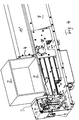
- the Fig. 1 shows a perspective top view of a part of a CNC machining center 10 with at least one transport rail 15, on which at least two clamping bars 7 are arranged transversely thereto and a clamping device 1 is arranged on the clamping bar 7.
- the jig 1 is In this exemplary embodiment, for practical reasons, it is arranged at one end of the clamping beam 7 in order to be able to machine an optimal size of a workpiece 2 to be machined on the CNC machining center 10.
- a stop element 17 for the workpiece 2 is firmly attached to the transport rails 15.
- the stop element 17 defines the end of the clearance of the workpiece 2 to be machined.
- a drive unit 18 is arranged that is essentially intended for the advance or movement of the workpiece 2 in the longitudinal direction of the transport rails 15.
- the Figure 2 shows a side view of the clamping device 1, in which a workpiece 2 to be machined lies between the clamping jaws 3 and 4.
- the clamping device 1 is arranged in an end region of the clamping beam 7.
- Each clamping beam 7 on the CNC machining center 10 has at least one clamping device 1.
- the clamping device 1 consists in principle of two clamping jaws 3, 4 each of which has a drive 11, 11 ', the drive 11' for the clamping jaw 4 not being shown in this illustration.
- the clamping jaw 4 is in the released state, that is, it is not in contact with the workpiece 2.
- the clamping jaw 4 touches the workpiece 2 on a vertical surface 2 '.
- the lower surface 2 ′′ of the workpiece 2 rests on at least one support rail 9, which is connected to the connecting element 8.
- the material from which the two clamping jaws 3, 4 and the support rail 9 are made is usually a plastic, for example Teflon, so as not to damage the surfaces of the workpiece 2 when clamping and unclamping the workpiece
- Support rails 9 are designed to be exchangeable and are selected depending on the material of the workpiece 2 to be machined.
- the clamping jaws 3, 4 are fastened to the respective devices with the fastening elements 22.
- the clamping jaw 3 is arranged on an angled connecting element 8, 8 '.
- the connecting element 8 connects the movable clamping jaw 3 to a joint 18 which forms the pivot point of the connecting element 8.
- the angled part 8 'of the connecting element 8 simultaneously forms the side wall of a housing in which the drive 11 of the clamping jaw 3 is arranged.
- the support rail 9 is essentially attached to the connecting element 8.
- the drive 11 is articulated at its lower end with a joint 20 on a support point 21 of the basic structure of the clamping beam 7.
- the drive 11 can be operated electrically, hydraulically or pneumatically. In the present exemplary embodiment, the drive 11 is operated pneumatically.
- the Figure 3 shows a side view of the clamping device 1, in which a workpiece 2 to be machined lies between the clamping jaws 3, 4 and the clamping jaws 3, 4 and the support rail 9 do not touch the entire surface of the workpiece 2.
- a workpiece 2 to be machined lies between the clamping jaws 3, 4 and the clamping jaws 3, 4 and the support rail 9 do not touch the entire surface of the workpiece 2.
- the lowering of the connecting element 8, 8 ' is brought about by the drive 11, which is described in more detail elsewhere.
- the Figure 4 shows a perspective side view of one end of the clamping beam 7, on which the clamping device 1 is arranged with the workpiece 2 suspended.
- the connecting element 8, 8 ′ between the joint 18 and the clamping jaw 3 is not shown in order to make the drive 11 for the clamping jaw 3 visible.
- the clamping jaw 3 is shown in the lowered state.
- the lowered state of the clamping jaw 3 is at the same time the relaxed state of the clamping device, in which the workpiece 2 hangs freely in the air between the clamping jaws 3, 4 and the support rail 9.
- the cylinder rod 24, which transmits the force of the drive 11 to the clamping jaw 3, is rotatably fastened to the mounting structure of the clamping jaw 3 by means of a joint 27.
- the drive 11 thus hangs movably between the two joints 20 and 27.
- the drive 11 is controlled electronically-pneumatically or in a similar way and, with the aid of the cylinder rod 24, can move the clamping jaw 3 within predetermined limits.
- a damping element 13 is fastened to the movable connecting element by means of a clamp 26.
- a defined stop element 14 is also arranged, on which the punch 27 of the damping element 13 strikes in order to achieve the rapid To slow down the movement of the clamping jaw 3 during the clamping process.
- the Figure 5 shows an enlarged, perspective illustration of the damping element 13, which is adjustably fastened with a clamp 26 to the movable part of a clamping jaw 3.
- the clamping device 1 is shown in its relaxed state, that is to say that the clamping jaws 3 and 4 do not touch the workpiece 2.
- a punch 28 protrudes from the cylinder of the damping element 13, the tip of which strikes a stop element 14 during the tensioning process of the tensioning device 1 and dampens the speed of the tensioning process when the punch 28 is pressed into the cylinder of the damping element 13.
- the stop element 14 is fastened to a stationary structural element 25 of the structure of the clamping device 1 and defines the end of the stroke of the clamping jaw 3.
- a clamping device 1 is presented on a CNC machining center, which enables a contactless displacement of at least one clamping beam 7.
- this new type of clamping device damage to the surface of a workpiece 2 to be machined is avoided because the workpiece 2 does not come into contact with either the clamping jaws 3, 4 or the support rail 9 below while the clamping beam 7 is being moved on the CNC machining center by means of a connecting element 8 which is arranged between a joint 18 and the movable clamping jaw 3, the clamping jaw 3 is lowered or removed together with the support rail 9.
- a predetermined corner point 5 describes on the clamping jaw 3 a curved path 6, so that with the rotary movement of the connecting element 8 and thus of the corner point 5, both the clamping jaw 3 and the support rail 9 are removed from the surface of the workpiece 2 to be machined at the same time.
Abstract
Mit der vorliegenden Erfindung wird eine Spannvorrichtung (1) vorgestellt, die auf einem CNC-Bearbeitungszentrum angeordnet ist. Mit dieser neuartigen Spannvorrichtung (1) wird eine Beschädigung der Oberfläche eines zu bearbeitenden Werkstücks (2) vermieden, weil das Werkstück (2) während des Verschiebens des Spannbalkens (7) auf dem CNC-Bearbeitungszentrum weder mit den beweglichen Spannbacken (3,4) noch mit der darunter liegenden Auflageschiene (9) in Berührung kommt, denn mittels mindestens eines Verbindungselements (8), das zwischen einem Gelenk (18) und der beweglichen Spannbacke (3) angeordnet ist, wird die bewegliche Spannbacke (3) zusammen mit der Auflageschiene (9) abgesenkt, bzw. von dem zu bearbeitenden Werkstück (2) entfernt. Während des Absenkvorgangs beschreibt ein bestimmter Eckpunkt (5) auf der Spannbacke (3) eine gekrümmte Bahn (6), sodass mit der Drehbewegung des Eckpunktes (5) sowohl die Spannbacke (3) als auch die Auflageschiene (9) gleichzeitig von der Oberfläche des zu bearbeitenden Werkstücks (2) entfernt wird.With the present invention, a clamping device (1) is presented, which is arranged on a CNC machining center. This new type of clamping device (1) prevents damage to the surface of a workpiece (2) to be machined, because the workpiece (2) is not connected to the movable clamping jaws (3,4) while the clamping beam (7) is being moved on the CNC machining center. still comes into contact with the underlying support rail (9), because by means of at least one connecting element (8), which is arranged between a joint (18) and the movable clamping jaw (3), the movable clamping jaw (3) together with the support rail (9) lowered or removed from the workpiece to be machined (2). During the lowering process, a certain corner point (5) on the clamping jaw (3) describes a curved path (6), so that with the turning movement of the corner point (5), both the clamping jaw (3) and the support rail (9) are lifted from the surface of the to be machined workpiece (2) is removed.
Description
Die vorliegende Erfindung betrifft ein Verfahren und eine Vorrichtung zum kontaktlosen Verschieben eines Spannbalkens auf einem CNC-Bearbeitungszentrum, insbesondere mit einer Spannvorrichtung auf einem Spannbalken, deren Spannbacken in besonderer Art und Weise relativ zueinander beweglich angeordnet sind und dadurch ein kontaktloses Versetzen mindestens eines Spannbalkens relativ zu dem zu bearbeitendes Werkstück ermöglicht.The present invention relates to a method and a device for the contactless displacement of a clamping beam on a CNC machining center, in particular with a clamping device on a clamping beam, the clamping jaws of which are arranged so as to be movable relative to one another in a special manner and thereby a contactless displacement of at least one clamping beam relative to allows the workpiece to be machined.
Derartige Vorrichtungen sind im Stand der Technik aus der
Weiterhin offenbart die Druckschrift G 95357 B eine Spannvorrichtung für Werkstücke auf einer CNC-gesteuerten Werkzeugmaschine mit einer Spannvorrichtung, die zum Einspannen eines Werkstückes zwischen 2 Spannbacken dient. Ferner ist aus der G 92 17 329.2 eine Spannvorrichtung mit einer beweglichen Spannbacke bekannt geworden, wobei die eine bewegliche Spannbacke mindestens ein Gelenk mit elastischfedernder Wirkung aufweist. Das elastisch-federnde Gelenk an der Spannbacke dient dazu, ein zu bearbeitendes Werkstück möglichst schnell ein- und ausspannen zu können. Die Spannvorrichtung ist dabei auf einer Grundplatte mit einem Nutraster angeordnet, in dem die Spannvorrichtung hin und her bewegt werden kann. Das einzuspannende Werkstück wird mit Hilfe eines Hebels zwischen den Spannbacken eingespannt, wobei sich die bewegliche Spannbacke aufgrund der Federwirkung des Gelenkes beim Lösen der Spannbacken ein wenig vom Werkstück löst.Furthermore, the publication G 95357 B discloses a clamping device for workpieces on a CNC-controlled Machine tool with a clamping device which is used to clamp a workpiece between 2 clamping jaws. Furthermore, from G 92 17 329.2 a clamping device with a movable clamping jaw has become known, the one movable clamping jaw having at least one joint with an elastic spring effect. The elastic-resilient joint on the clamping jaw is used to be able to clamp and unclamp a workpiece to be machined as quickly as possible. The clamping device is arranged on a base plate with a groove grid in which the clamping device can be moved back and forth. The workpiece to be clamped is clamped between the clamping jaws with the aid of a lever, the movable clamping jaw being released a little from the workpiece when the clamping jaws are loosened due to the spring action of the joint.
Als nachteilig im Stand der Technik wird es empfunden, dass unter anderem entweder die Spannbacken oder die Auflage, auf dem das Werkstück aufliegt, zumindest beim Versetzen der Spannvorrichtung des Spannbalkens, um das Werkstück an einer anderen Stelle zu bearbeiten, stets während des Verschiebevorgangs mit dem Werkstück in Berührung steht, wodurch infolge von hängengebliebenen Spänen oder ähnlichen Ablagerungen oder aber durch die Spannbacken selbst ungewollt Kratzer oder Riefen oder Vertiefungen an der Oberfläche des Werkstücks eingezogen werden können, die das Werkstück zumindest in seinem Wert mindern.It is felt to be disadvantageous in the prior art that, among other things, either the clamping jaws or the support on which the workpiece rests, at least when the clamping device of the clamping beam is moved in order to process the workpiece at a different point, always during the displacement process with the The workpiece is in contact, which can result in unwanted scratches or grooves or depressions being drawn in on the surface of the workpiece as a result of stuck chips or similar deposits or through the clamping jaws themselves, which at least reduce the workpiece's value.
Daher ist es Aufgabe der vorliegenden Erfindung, ein Verfahren bzw. eine Vorrichtung bereitzustellen, die in der Lage sind, die Nachteile aus dem Stand der Technik zu beseitigen.It is therefore the object of the present invention to provide a method and a device which are able to eliminate the disadvantages of the prior art.
Diese Aufgabe wird mit den kennzeichnenden Merkmalen der Hauptansprüche, sowie den Merkmalen in den Unteransprüchen und der Beschreibung, sowie den Zeichnungen gelöst.This object is achieved with the characterizing features of the main claims, as well as the features in the subclaims and the description, as well as the drawings.
Erfindungsgemäß ist das Verfahren zum kontaktlosen Verschieben zumindest eines Spannbalkens auf einem CNC-Bearbeitungszentrum, dadurch gekennzeichnet, dass der mindestens eine Spannbalken versetzt werden kann, ohne ein einzuspannendes Werkstück während des Verschiebevorgangs des Spannbalkens zu berühren.According to the invention, the method for non-contact displacement of at least one clamping beam on a CNC machining center is characterized in that the at least one clamping beam can be moved without touching a workpiece to be clamped during the displacement process of the clamping beam.
Dabei ist es vorteilhaft und notwendig, dass mindestens eine Spannbacke auf einem Spannbalken angeordnet ist und mindestens ein Punkt der mindestens einen Spannbacke eine Bewegung auf einer gekrümmten Bahn ausführt.It is advantageous and necessary that at least one clamping jaw is arranged on a clamping beam and at least one point of the at least one clamping jaw executes a movement on a curved path.
Die erfindungsgemäße Spannvorrichtung zum Befestigen eines Werkstückes auf einem CNC-Bearbeitungszentrum mit einer Mehrzahl an Spannbalken auf dem die Spannvorrichtung mit mindestens einer beweglichen Spannbacke angeordnet ist, ist dadurch gekennzeichnet, dass sich mindestens ein Punkt der beweglichen Spannbacke auf einer Bahn bewegt, die mindestens eine Krümmung aufweist.The clamping device according to the invention for fastening a workpiece on a CNC machining center with a plurality of clamping bars on which the clamping device with at least one movable clamping jaw is arranged, is characterized in that at least one point of the movable clamping jaw moves on a path that has at least one curvature having.
Dabei ist es vorteilhaft, dass die mindestens eine Krümmung beispielsweise als Kreisbahn ausgebildet ist, die zum Entspannen des Werkstückes in der Spannvorrichtung dient.It is advantageous here that the at least one curvature is designed, for example, as a circular path which is used to relax the workpiece in the clamping device.
Ferner ist es vorteilhaft, dass die mindestens eine Spannbacke gelenkig mit mindestens einem Punkt des Spannbalkens verbunden ist.Furthermore, it is advantageous that the at least one clamping jaw is connected in an articulated manner to at least one point of the clamping beam.
Weiterhin ist es vorteilhaft, dass die mindestens eine Spannbacke mit mindestens einem Verbindungselement, das als Hebelarm ausgebildet sein kann, verbunden ist.Furthermore, it is advantageous that the at least one clamping jaw is connected to at least one connecting element, which can be designed as a lever arm.
Ein weiterer Vorteil ist darin zu sehen, dass die mindestens eine Spannbacke gelenkig mit einem Antrieb verbunden ist, wobei das andere Ende des Antriebs gelenkig mit dem Spannbalken verbunden ist.Another advantage is that the at least one clamping jaw is articulated to a drive, the other end of the drive being articulated to the clamping beam.
Ferner ist es vorteilhaft, dass die bewegliche Spannbacke mindestens ein Dämpfungselement und mindestens ein Anschlagelement aufweist.Furthermore, it is advantageous that the movable clamping jaw has at least one damping element and at least one stop element.
Ein weiterer Vorteil ist darin zu sehen, dass auf mindestens einer Transportschiene mindestens zwei Spannbalken angeordnet sind, die quer zur Längsachse der mindestens einen Transportschiene bewegt werden können.A further advantage can be seen in the fact that at least two clamping bars are arranged on at least one transport rail, and can be moved transversely to the longitudinal axis of the at least one transport rail.
Vorteilhaft ist es auch, dass die Spannvorrichtung elektrisch oder hydraulisch oder pneumatisch betrieben wird und elektronisch ansteuerbar ist.It is also advantageous that the clamping device is operated electrically or hydraulically or pneumatically and can be controlled electronically.
Vorteilhaft ist es ferner, dass der Antrieb im Bereich eines Endes des Spannbalkens angeordnet ist.It is also advantageous that the drive is arranged in the area of one end of the clamping beam.
Weitere erfindungswesentliche Merkmale gehen aus den Unteransprüchen, der Beschreibung und der Zeichnungen hervor.Further features essential to the invention emerge from the subclaims, the description and the drawings.
Im nun Folgenden wird die Erfindung anhand von Zeichnungen im Detail näher beschrieben. Es zeigt
- Fig. 1:
- eine perspektivische Draufsicht auf einen Teil eines CNC-Bearbeitungszentrums (10) mit mindestens einer Transportschiene (15), auf der quer dazu mindestens zwei Spannbalken (7) angeordnet sind und auf den Spannbalken (7) die Spannvorrichtung (1) angeordnet ist;
- Fig. 2:
- eine Seitenansicht der Spannvorrichtung (1), bei der ein zu bearbeitendes Werkstück (2) zwischen den Spannbacken (3,4) einliegt;
- Fig. 3:
- eine Seitenansicht der Spannvorrichtung (1) bei der ein zu bearbeitendes Werkstück (2) zwischen den Spannbacken (3,4) einliegt und die Spannbacken (3,4) die Oberfläche des Werkstücks (2) nicht berühren;
- Fig. 4:
- eine perspektivische Seitenansicht des einen Endes des Spannbalken (7) auf dem die Spannvorrichtung (1) in geöffnetem Zustand mit eingelegtem Werkstück (2) angeordnet ist;
- Fig. 5
- eine vergrößerte, perspektivische Allein-Darstellung des
Dämpfungselements 13, das mit einerSchelle 26 an dem beweglichen Teil einerSpannbacke 3 einstellbar befestigt ist.
- Fig. 1:
- a perspective top view of part of a CNC machining center (10) with at least one transport rail (15) on which at least two clamping bars (7) are arranged transversely thereto and the clamping device (1) is arranged on the clamping bar (7);
- Fig. 2:
- a side view of the clamping device (1), in which a workpiece (2) to be machined lies between the clamping jaws (3, 4);
- Fig. 3:
- a side view of the clamping device (1) in which a workpiece (2) to be machined lies between the clamping jaws (3, 4) and the clamping jaws (3, 4) do not touch the surface of the workpiece (2);
- Fig. 4:
- a perspective side view of one end of the clamping beam (7) on which the clamping device (1) is arranged in the open state with the workpiece (2) inserted;
- Fig. 5
- an enlarged, perspective illustration of the
damping element 13, which is adjustably fastened with aclamp 26 to the movable part of aclamping jaw 3.
Die
Die
Die
Die
Die
Zusammenfassend darf festgestellt werden, dass mit der vorliegenden Erfindung eine Spannvorrichtung 1 auf einem CNC-Bearbeitungszentrums vorgestellt wird, die ein berührungsloses Verschieben mindestens eines Spannbalkens 7 ermöglicht. Mit dieser neuartigen Spannvorrichtung 1 wird eine Beschädigung der Oberfläche eines zu bearbeitenden Werkstücks 2 vermieden, weil das Werkstück 2 während des Verschiebens des Spannbalkens 7 auf dem CNC-Bearbeitungszentrum weder mit den Spannbacken 3,4 noch mit der darunterliegenden Auflageschiene 9 in Berührung kommt, denn mittels eines Verbindungselementes 8, das zwischen einem Gelenk 18 und der beweglichen Spannbacke 3 angeordnet ist, wird die Spannbacke 3 zusammen mit der Auflageschiene 9 abgesenkt, bzw. entfernt. Während des Absenkvorgangs beschreibt ein vorbestimmter Eckpunkt 5 auf der Spannbacke 3 eine gekrümmte Bahn 6, sodass mit der Drehbewegung des Verbindungselements 8 und damit des Eckpunktes 5 sowohl die Spannbacke 3 als auch die Auflageschiene 9 gleichzeitig von der Oberfläche des zu bearbeitenden Werkstücks 2 entfernt wird.In summary, it can be stated that with the present invention a
Claims (11)
Priority Applications (1)
| Application Number | Priority Date | Filing Date | Title |
|---|---|---|---|
| EP20000282.2A EP3932613B1 (en) | 2020-08-10 | 2020-08-10 | Method and device for contactless displacement of a tension bar on a cnc machining centre |
Applications Claiming Priority (1)
| Application Number | Priority Date | Filing Date | Title |
|---|---|---|---|
| EP20000282.2A EP3932613B1 (en) | 2020-08-10 | 2020-08-10 | Method and device for contactless displacement of a tension bar on a cnc machining centre |
Publications (2)
| Publication Number | Publication Date |
|---|---|
| EP3932613A1 true EP3932613A1 (en) | 2022-01-05 |
| EP3932613B1 EP3932613B1 (en) | 2023-02-22 |
Family
ID=72050636
Family Applications (1)
| Application Number | Title | Priority Date | Filing Date |
|---|---|---|---|
| EP20000282.2A Active EP3932613B1 (en) | 2020-08-10 | 2020-08-10 | Method and device for contactless displacement of a tension bar on a cnc machining centre |
Country Status (1)
| Country | Link |
|---|---|
| EP (1) | EP3932613B1 (en) |
Cited By (1)
| Publication number | Priority date | Publication date | Assignee | Title |
|---|---|---|---|---|
| EP4069462A4 (en) * | 2020-04-08 | 2022-12-28 | Peddinghaus Corporation | System and method for processing a workpiece |
Citations (4)
| Publication number | Priority date | Publication date | Assignee | Title |
|---|---|---|---|---|
| EP1555084A1 (en) * | 2004-01-13 | 2005-07-20 | Mubea Systems, Société Anonyme | Machine tool with longitudinally slidable clamps with own driving means |
| DE10331338B4 (en) | 2003-07-10 | 2006-03-16 | Westphal Maschinenbau Gmbh | Automatic positioning system |
| CN106002410A (en) * | 2016-07-21 | 2016-10-12 | 桐乡守敬应用技术研究院有限公司 | Swinging type clamping device |
| EP3098024A1 (en) * | 2015-05-29 | 2016-11-30 | Kaltenbach GmbH + Co. KG | Clamping device |
-
2020
- 2020-08-10 EP EP20000282.2A patent/EP3932613B1/en active Active
Patent Citations (4)
| Publication number | Priority date | Publication date | Assignee | Title |
|---|---|---|---|---|
| DE10331338B4 (en) | 2003-07-10 | 2006-03-16 | Westphal Maschinenbau Gmbh | Automatic positioning system |
| EP1555084A1 (en) * | 2004-01-13 | 2005-07-20 | Mubea Systems, Société Anonyme | Machine tool with longitudinally slidable clamps with own driving means |
| EP3098024A1 (en) * | 2015-05-29 | 2016-11-30 | Kaltenbach GmbH + Co. KG | Clamping device |
| CN106002410A (en) * | 2016-07-21 | 2016-10-12 | 桐乡守敬应用技术研究院有限公司 | Swinging type clamping device |
Cited By (1)
| Publication number | Priority date | Publication date | Assignee | Title |
|---|---|---|---|---|
| EP4069462A4 (en) * | 2020-04-08 | 2022-12-28 | Peddinghaus Corporation | System and method for processing a workpiece |
Also Published As
| Publication number | Publication date |
|---|---|
| EP3932613B1 (en) | 2023-02-22 |
Similar Documents
| Publication | Publication Date | Title |
|---|---|---|
| DE3535616C2 (en) | ||
| EP2894006B1 (en) | Device for tensioning, holding and positioning a workpiece | |
| EP3356098A1 (en) | Machining device | |
| EP3197639A1 (en) | Machining device | |
| EP2874804A1 (en) | Cam drive | |
| DE202008012632U1 (en) | Machining machine for six-sided machining | |
| AT403812B (en) | MACHINE FOR PRESSING THRESHOLD ANCHORS | |
| DE2801249C2 (en) | Deburring device in a butt welding machine guided on a rail line to be deburred | |
| EP3932613B1 (en) | Method and device for contactless displacement of a tension bar on a cnc machining centre | |
| DE2550819C2 (en) | ||
| DE3035657C2 (en) | ||
| DE102006019115A1 (en) | Plate gripping device for automatic borer-cutter-importer, has arresting unit comprising small vertical extension, and guiding unit designed such that edge of plate is attached to it for providing position reference for edge | |
| DE102014222423A1 (en) | jig | |
| EP3326748A1 (en) | Method for machining | |
| DE1265676B (en) | Spring clamps | |
| DE7537486U (en) | REVOLVING PRESS | |
| DE713451C (en) | Pliers designed for clamping workpieces | |
| DE2951078C1 (en) | Miter box | |
| DE2151967C3 (en) | Wood turning machine | |
| DE945887C (en) | Feeding device to chipping, trimming machines or the like for extremely short screw bolts | |
| DE2340153A1 (en) | METHOD AND DEVICE FOR ALIGNING CURVED LONGITUDINAL OBJECTS CONSTANT CROSS SECTION | |
| EP2998065B1 (en) | Processing device with a workpiece table | |
| DE828943C (en) | Jaws for a clamping device for workpieces | |
| AT383301B (en) | Gripper construction for an industrial robot | |
| DE3432672C2 (en) |
Legal Events
| Date | Code | Title | Description |
|---|---|---|---|
| PUAI | Public reference made under article 153(3) epc to a published international application that has entered the european phase |
Free format text: ORIGINAL CODE: 0009012 |
|
| STAA | Information on the status of an ep patent application or granted ep patent |
Free format text: STATUS: REQUEST FOR EXAMINATION WAS MADE |
|
| 17P | Request for examination filed |
Effective date: 20200824 |
|
| AK | Designated contracting states |
Kind code of ref document: A1 Designated state(s): AL AT BE BG CH CY CZ DE DK EE ES FI FR GB GR HR HU IE IS IT LI LT LU LV MC MK MT NL NO PL PT RO RS SE SI SK SM TR |
|
| B565 | Issuance of search results under rule 164(2) epc |
Effective date: 20210120 |
|
| GRAP | Despatch of communication of intention to grant a patent |
Free format text: ORIGINAL CODE: EPIDOSNIGR1 |
|
| STAA | Information on the status of an ep patent application or granted ep patent |
Free format text: STATUS: GRANT OF PATENT IS INTENDED |
|
| INTG | Intention to grant announced |
Effective date: 20220330 |
|
| GRAS | Grant fee paid |
Free format text: ORIGINAL CODE: EPIDOSNIGR3 |
|
| GRAA | (expected) grant |
Free format text: ORIGINAL CODE: 0009210 |
|
| STAA | Information on the status of an ep patent application or granted ep patent |
Free format text: STATUS: THE PATENT HAS BEEN GRANTED |
|
| AK | Designated contracting states |
Kind code of ref document: B1 Designated state(s): AL AT BE BG CH CY CZ DE DK EE ES FI FR GB GR HR HU IE IS IT LI LT LU LV MC MK MT NL NO PL PT RO RS SE SI SK SM TR |
|
| REG | Reference to a national code |
Ref country code: GB Ref legal event code: FG4D Free format text: NOT ENGLISH |
|
| REG | Reference to a national code |
Ref country code: CH Ref legal event code: EP |
|
| REG | Reference to a national code |
Ref country code: AT Ref legal event code: REF Ref document number: 1549208 Country of ref document: AT Kind code of ref document: T Effective date: 20230315 Ref country code: IE Ref legal event code: FG4D Free format text: LANGUAGE OF EP DOCUMENT: GERMAN |
|
| REG | Reference to a national code |
Ref country code: DE Ref legal event code: R096 Ref document number: 502020002543 Country of ref document: DE |
|
| REG | Reference to a national code |
Ref country code: LT Ref legal event code: MG9D |
|
| REG | Reference to a national code |
Ref country code: NL Ref legal event code: MP Effective date: 20230222 |
|
| PG25 | Lapsed in a contracting state [announced via postgrant information from national office to epo] |
Ref country code: RS Free format text: LAPSE BECAUSE OF FAILURE TO SUBMIT A TRANSLATION OF THE DESCRIPTION OR TO PAY THE FEE WITHIN THE PRESCRIBED TIME-LIMIT Effective date: 20230222 Ref country code: PT Free format text: LAPSE BECAUSE OF FAILURE TO SUBMIT A TRANSLATION OF THE DESCRIPTION OR TO PAY THE FEE WITHIN THE PRESCRIBED TIME-LIMIT Effective date: 20230622 Ref country code: NO Free format text: LAPSE BECAUSE OF FAILURE TO SUBMIT A TRANSLATION OF THE DESCRIPTION OR TO PAY THE FEE WITHIN THE PRESCRIBED TIME-LIMIT Effective date: 20230522 Ref country code: NL Free format text: LAPSE BECAUSE OF FAILURE TO SUBMIT A TRANSLATION OF THE DESCRIPTION OR TO PAY THE FEE WITHIN THE PRESCRIBED TIME-LIMIT Effective date: 20230222 Ref country code: LV Free format text: LAPSE BECAUSE OF FAILURE TO SUBMIT A TRANSLATION OF THE DESCRIPTION OR TO PAY THE FEE WITHIN THE PRESCRIBED TIME-LIMIT Effective date: 20230222 Ref country code: LT Free format text: LAPSE BECAUSE OF FAILURE TO SUBMIT A TRANSLATION OF THE DESCRIPTION OR TO PAY THE FEE WITHIN THE PRESCRIBED TIME-LIMIT Effective date: 20230222 Ref country code: HR Free format text: LAPSE BECAUSE OF FAILURE TO SUBMIT A TRANSLATION OF THE DESCRIPTION OR TO PAY THE FEE WITHIN THE PRESCRIBED TIME-LIMIT Effective date: 20230222 Ref country code: ES Free format text: LAPSE BECAUSE OF FAILURE TO SUBMIT A TRANSLATION OF THE DESCRIPTION OR TO PAY THE FEE WITHIN THE PRESCRIBED TIME-LIMIT Effective date: 20230222 |
|
| PG25 | Lapsed in a contracting state [announced via postgrant information from national office to epo] |
Ref country code: SE Free format text: LAPSE BECAUSE OF FAILURE TO SUBMIT A TRANSLATION OF THE DESCRIPTION OR TO PAY THE FEE WITHIN THE PRESCRIBED TIME-LIMIT Effective date: 20230222 Ref country code: PL Free format text: LAPSE BECAUSE OF FAILURE TO SUBMIT A TRANSLATION OF THE DESCRIPTION OR TO PAY THE FEE WITHIN THE PRESCRIBED TIME-LIMIT Effective date: 20230222 Ref country code: IS Free format text: LAPSE BECAUSE OF FAILURE TO SUBMIT A TRANSLATION OF THE DESCRIPTION OR TO PAY THE FEE WITHIN THE PRESCRIBED TIME-LIMIT Effective date: 20230622 Ref country code: GR Free format text: LAPSE BECAUSE OF FAILURE TO SUBMIT A TRANSLATION OF THE DESCRIPTION OR TO PAY THE FEE WITHIN THE PRESCRIBED TIME-LIMIT Effective date: 20230523 Ref country code: FI Free format text: LAPSE BECAUSE OF FAILURE TO SUBMIT A TRANSLATION OF THE DESCRIPTION OR TO PAY THE FEE WITHIN THE PRESCRIBED TIME-LIMIT Effective date: 20230222 |
|
| PGFP | Annual fee paid to national office [announced via postgrant information from national office to epo] |
Ref country code: LU Payment date: 20230830 Year of fee payment: 4 |
|
| PG25 | Lapsed in a contracting state [announced via postgrant information from national office to epo] |
Ref country code: SM Free format text: LAPSE BECAUSE OF FAILURE TO SUBMIT A TRANSLATION OF THE DESCRIPTION OR TO PAY THE FEE WITHIN THE PRESCRIBED TIME-LIMIT Effective date: 20230222 Ref country code: RO Free format text: LAPSE BECAUSE OF FAILURE TO SUBMIT A TRANSLATION OF THE DESCRIPTION OR TO PAY THE FEE WITHIN THE PRESCRIBED TIME-LIMIT Effective date: 20230222 Ref country code: EE Free format text: LAPSE BECAUSE OF FAILURE TO SUBMIT A TRANSLATION OF THE DESCRIPTION OR TO PAY THE FEE WITHIN THE PRESCRIBED TIME-LIMIT Effective date: 20230222 Ref country code: DK Free format text: LAPSE BECAUSE OF FAILURE TO SUBMIT A TRANSLATION OF THE DESCRIPTION OR TO PAY THE FEE WITHIN THE PRESCRIBED TIME-LIMIT Effective date: 20230222 Ref country code: CZ Free format text: LAPSE BECAUSE OF FAILURE TO SUBMIT A TRANSLATION OF THE DESCRIPTION OR TO PAY THE FEE WITHIN THE PRESCRIBED TIME-LIMIT Effective date: 20230222 |
|
| PGFP | Annual fee paid to national office [announced via postgrant information from national office to epo] |
Ref country code: IT Payment date: 20230831 Year of fee payment: 4 Ref country code: CH Payment date: 20230902 Year of fee payment: 4 |
|
| REG | Reference to a national code |
Ref country code: DE Ref legal event code: R097 Ref document number: 502020002543 Country of ref document: DE |
|
| PG25 | Lapsed in a contracting state [announced via postgrant information from national office to epo] |
Ref country code: SK Free format text: LAPSE BECAUSE OF FAILURE TO SUBMIT A TRANSLATION OF THE DESCRIPTION OR TO PAY THE FEE WITHIN THE PRESCRIBED TIME-LIMIT Effective date: 20230222 |
|
| PGFP | Annual fee paid to national office [announced via postgrant information from national office to epo] |
Ref country code: FR Payment date: 20230830 Year of fee payment: 4 Ref country code: DE Payment date: 20230831 Year of fee payment: 4 Ref country code: BE Payment date: 20230829 Year of fee payment: 4 |
|
| PLBE | No opposition filed within time limit |
Free format text: ORIGINAL CODE: 0009261 |
|
| STAA | Information on the status of an ep patent application or granted ep patent |
Free format text: STATUS: NO OPPOSITION FILED WITHIN TIME LIMIT |
|
| 26N | No opposition filed |
Effective date: 20231123 |
|
| PG25 | Lapsed in a contracting state [announced via postgrant information from national office to epo] |
Ref country code: SI Free format text: LAPSE BECAUSE OF FAILURE TO SUBMIT A TRANSLATION OF THE DESCRIPTION OR TO PAY THE FEE WITHIN THE PRESCRIBED TIME-LIMIT Effective date: 20230222 |
|
| PG25 | Lapsed in a contracting state [announced via postgrant information from national office to epo] |
Ref country code: MC Free format text: LAPSE BECAUSE OF FAILURE TO SUBMIT A TRANSLATION OF THE DESCRIPTION OR TO PAY THE FEE WITHIN THE PRESCRIBED TIME-LIMIT Effective date: 20230222 |
|
| PG25 | Lapsed in a contracting state [announced via postgrant information from national office to epo] |
Ref country code: MC Free format text: LAPSE BECAUSE OF FAILURE TO SUBMIT A TRANSLATION OF THE DESCRIPTION OR TO PAY THE FEE WITHIN THE PRESCRIBED TIME-LIMIT Effective date: 20230222 |