EP3929342B1 - Verfahren zur herstellung eines befestigungssystems für ein haushaltsgerät - Google Patents
Verfahren zur herstellung eines befestigungssystems für ein haushaltsgerät Download PDFInfo
- Publication number
- EP3929342B1 EP3929342B1 EP21177123.3A EP21177123A EP3929342B1 EP 3929342 B1 EP3929342 B1 EP 3929342B1 EP 21177123 A EP21177123 A EP 21177123A EP 3929342 B1 EP3929342 B1 EP 3929342B1
- Authority
- EP
- European Patent Office
- Prior art keywords
- fastening system
- hole
- sheet metal
- metal wall
- clinching
- Prior art date
- Legal status (The legal status is an assumption and is not a legal conclusion. Google has not performed a legal analysis and makes no representation as to the accuracy of the status listed.)
- Active
Links
Images
Classifications
-
- D—TEXTILES; PAPER
- D06—TREATMENT OF TEXTILES OR THE LIKE; LAUNDERING; FLEXIBLE MATERIALS NOT OTHERWISE PROVIDED FOR
- D06F—LAUNDERING, DRYING, IRONING, PRESSING OR FOLDING TEXTILE ARTICLES
- D06F39/00—Details of washing machines not specific to a single type of machines covered by groups D06F9/00 - D06F27/00
- D06F39/12—Casings; Tubs
-
- B—PERFORMING OPERATIONS; TRANSPORTING
- B21—MECHANICAL METAL-WORKING WITHOUT ESSENTIALLY REMOVING MATERIAL; PUNCHING METAL
- B21D—WORKING OR PROCESSING OF SHEET METAL OR METAL TUBES, RODS OR PROFILES WITHOUT ESSENTIALLY REMOVING MATERIAL; PUNCHING METAL
- B21D39/00—Application of procedures in order to connect objects or parts, e.g. coating with sheet metal otherwise than by plating; Tube expanders
- B21D39/03—Application of procedures in order to connect objects or parts, e.g. coating with sheet metal otherwise than by plating; Tube expanders of sheet metal otherwise than by folding
- B21D39/031—Joining superposed plates by locally deforming without slitting or piercing
-
- F—MECHANICAL ENGINEERING; LIGHTING; HEATING; WEAPONS; BLASTING
- F16—ENGINEERING ELEMENTS AND UNITS; GENERAL MEASURES FOR PRODUCING AND MAINTAINING EFFECTIVE FUNCTIONING OF MACHINES OR INSTALLATIONS; THERMAL INSULATION IN GENERAL
- F16B—DEVICES FOR FASTENING OR SECURING CONSTRUCTIONAL ELEMENTS OR MACHINE PARTS TOGETHER, e.g. NAILS, BOLTS, CIRCLIPS, CLAMPS, CLIPS OR WEDGES; JOINTS OR JOINTING
- F16B25/00—Screws that cut thread in the body into which they are screwed, e.g. wood screws
- F16B25/001—Screws that cut thread in the body into which they are screwed, e.g. wood screws characterised by the material of the body into which the screw is screwed
- F16B25/0021—Screws that cut thread in the body into which they are screwed, e.g. wood screws characterised by the material of the body into which the screw is screwed the material being metal, e.g. sheet-metal or aluminium
-
- F—MECHANICAL ENGINEERING; LIGHTING; HEATING; WEAPONS; BLASTING
- F16—ENGINEERING ELEMENTS AND UNITS; GENERAL MEASURES FOR PRODUCING AND MAINTAINING EFFECTIVE FUNCTIONING OF MACHINES OR INSTALLATIONS; THERMAL INSULATION IN GENERAL
- F16B—DEVICES FOR FASTENING OR SECURING CONSTRUCTIONAL ELEMENTS OR MACHINE PARTS TOGETHER, e.g. NAILS, BOLTS, CIRCLIPS, CLAMPS, CLIPS OR WEDGES; JOINTS OR JOINTING
- F16B37/00—Nuts or like thread-engaging members
- F16B37/005—Nuts or like thread-engaging members into which threads are cut during screwing
-
- F—MECHANICAL ENGINEERING; LIGHTING; HEATING; WEAPONS; BLASTING
- F16—ENGINEERING ELEMENTS AND UNITS; GENERAL MEASURES FOR PRODUCING AND MAINTAINING EFFECTIVE FUNCTIONING OF MACHINES OR INSTALLATIONS; THERMAL INSULATION IN GENERAL
- F16B—DEVICES FOR FASTENING OR SECURING CONSTRUCTIONAL ELEMENTS OR MACHINE PARTS TOGETHER, e.g. NAILS, BOLTS, CIRCLIPS, CLAMPS, CLIPS OR WEDGES; JOINTS OR JOINTING
- F16B37/00—Nuts or like thread-engaging members
- F16B37/02—Nuts or like thread-engaging members made of thin sheet material
-
- F—MECHANICAL ENGINEERING; LIGHTING; HEATING; WEAPONS; BLASTING
- F16—ENGINEERING ELEMENTS AND UNITS; GENERAL MEASURES FOR PRODUCING AND MAINTAINING EFFECTIVE FUNCTIONING OF MACHINES OR INSTALLATIONS; THERMAL INSULATION IN GENERAL
- F16B—DEVICES FOR FASTENING OR SECURING CONSTRUCTIONAL ELEMENTS OR MACHINE PARTS TOGETHER, e.g. NAILS, BOLTS, CIRCLIPS, CLAMPS, CLIPS OR WEDGES; JOINTS OR JOINTING
- F16B5/00—Joining sheets or plates, e.g. panels, to one another or to strips or bars parallel to them
- F16B5/04—Joining sheets or plates, e.g. panels, to one another or to strips or bars parallel to them by means of riveting
- F16B5/045—Joining sheets or plates, e.g. panels, to one another or to strips or bars parallel to them by means of riveting without the use of separate rivets
Definitions
- the invention relates to a method for producing a fastening system for a household appliance of the type mentioned in the preamble of patent claim 1.
- the known fastening systems for household appliances comprise a sheet metal wall of the household appliance and a reinforcing sheet, wherein the reinforcing sheet is designed as a component that is separate from the sheet metal wall in a disassembled state of the fastening system and the fastening system, in an assembled state of the fastening system in which the sheet metal wall and the reinforcing sheet are connected to one another, has at least one through hole penetrating the sheet metal wall and the reinforcing sheet in an area of the fastening system reinforced by means of the reinforcing sheet for force-transmitting reception of a screw corresponding to the through hole for fastening a component of the household appliance to the fastening system.
- the invention therefore addresses the problem of improving a method for producing a fastening system for a household appliance.
- the household appliance can be, for example, a laundry machine such as a washing machine, a tumble dryer or a washer-dryer.
- the component to be connected to the sheet metal wall of the household appliance in a force-transmitting manner can be, for example, a door of the household appliance that is pivotably arranged on the sheet metal wall for closing a loading opening of the household appliance.
- the invention can also be used to advantage in other types of household appliances as well as in devices for professional use, i.e. devices for commercial use.
- the clinching process is also known as Eckold joining, clinching or press joining.
- the advantage that can be achieved with the invention is in particular that a fastening system for a household appliance and a method for its production are improved. Due to the inventive design of the fastening system for a household appliance and the method for its production, for example, the manufacturing process for producing the fastening system according to the invention and thus the household appliance as well as the assembly process for the force-transmitting connection of a component to the rest of the household appliance are significantly simplified on the one hand. The number of required process steps, for example for storage, transport and during production, can be significantly reduced by the inventive method. This applies in particular to the preferred embodiment of the inventive method. On the other hand, sufficiently high forces can be transmitted between the component and the sheet metal wall of the household appliance reinforced by means of the reinforcing sheet by means of the force-transmitting connection realized in this way.
- the fastening system according to the invention can be freely selected within wide suitable limits in terms of type, mode of operation, material, dimensions and arrangement.
- the screw-in torque is as low as possible and the overtightening torque is as high as possible, so that the largest possible processing window is created for producing the force-transmitting connection between the component on the one side and the fastening system on the other side.
- the through hole is designed as a pure through hole.
- the through hole is realized in a particularly simple manner in terms of construction and production technology.
- the through hole has a passage, wherein the passage is arranged in an area of the fastening plate and/or in an area of the reinforcing plate. This ensures that the screw screwed into the through hole has enough threads to transmit the force, even when there are higher demands on the force transmission between the component and the fastening system. Due to the passage, it is also possible to form the sheet metal wall and the reinforcing plate with lower material thicknesses.
- a particularly advantageous development of the fastening system according to the invention provides that the at least one through hole is arranged in one of the at least one clinching points.
- the at least one through hole is very space-saving and can be implemented in a particularly simple manner in terms of production technology.
- the clinching point with the through hole has a clinching point base at least before the production of this through hole, wherein the through hole is arranged in the clinching point base or is formed by removing the clinching point base from the clinching point.
- the clinching point base of the clinching point can be punched or pierced out of the clinching point in a manner known to those skilled in the art.
- a further advantageous development of the fastening system according to the invention provides that the sheet metal wall and the reinforcing sheet are connected to one another in a liquid-tight manner in the assembled state of the fastening system by means of the at least one clinching point in the clinching point. In this way, it is ensured that, for example, dirt or liquid does not penetrate in an undesirable manner from the outside between the sheet metal wall and the reinforcing sheet via the through hole.
- the method according to the invention for producing a fastening system can be freely selected within wide suitable limits.
- the method according to the invention provides that the reinforcing sheet is produced as a waste product during the manufacture of the sheet metal wall and is configured for use as a reinforcing sheet for the fastening system according to the invention. This means that the addition of another component to the manufacturing process is not necessary. This simplifies storage, transport and production of the fastening system according to the invention and thus of the household appliance. This also significantly reduces the amount of waste produced during production, which also reduces logistics and the costs of disposing of the waste.
- FIG. 1 to 3b an embodiment of the fastening system according to the invention for a household appliance is shown purely by way of example.
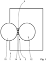
- the fastening system 2 for a household appliance 1 designed as a washing machine for laundry comprises a sheet metal wall 4 of the household appliance 1 and a reinforcing sheet 6, wherein the reinforcing sheet 6 is designed as a component that is separate from the sheet metal wall 4 in a disassembly state of the fastening system 2 (not shown) and the fastening system 2 is in a Fig.
- the component 10 is designed in the present exemplary embodiment as a door for closing a loading opening 12 of the household appliance 1.
- the door 10 is connected to the fastening system 2 in a force-transmitting manner by means of a fitting part 14 of the door 10 and the two screws 9 in the manner explained in more detail below.
- the sheet metal wall 4 and the reinforcing sheet 6 are permanently connected to one another in the assembled state of the fastening system 2 by means of two clinching points 16. See the Fig. 3a , which in the aforementioned context also applies to the first to third variants of the present embodiment.
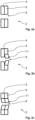
- the through holes 8 are designed as pure through holes.
- the through holes 8 have There is no draught in each case. See the Fig. 2a , in which one of the two through holes 8 is shown as an example.
- the through holes 8 each have a passage 11, wherein the respective passage 11 is arranged in a region of the fastening plate 4 and/or in a region of the reinforcing plate 6.
- the passage 11 of the second variant according to the Fig. 2b only in the area of the reinforcing plate 6, i.e. on the reinforcing plate 6, while the through hole 8 in the area of the sheet metal wall 4 is formed as a pure through hole.
- the passage 11 is arranged both in the area of the sheet metal wall 4 and in the area of the reinforcing sheet 6.
- the through holes 8, with or without passage 11, are arranged separately from the two clinching points 16, by means of which the sheet metal wall 4 and the reinforcing sheet 6 are permanently connected to one another in the assembled state of the fastening system 2, in the area of the fastening system 2 reinforced by the reinforcing sheet 6.
- the through holes 8 are arranged as close as possible to the clinching points 16.
- the screwing-in torque is as low as possible and the overtightening torque is as high as possible, so that the largest possible processing window is obtained for producing the force-transmitting connection between the component 10 on the one side and the fastening system 2 on the other side.
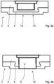
- one of the through holes 8 is arranged in one of the two penetration points 16. See the Fig. 3a and 3b , in which one of the two clinching points 16 is shown as an example. The other clinching point 16 is designed identically.
- the respective clinching point 16 with the corresponding through hole 8 has a clinching point base 18 before the production of this through hole 8, wherein this through hole 8 is formed after removal of this clinching point base 18 from the clinching point 16.
- Fig. 3a is the The clinching point base 18 has not yet been removed and the corresponding through hole 8 has not yet been formed in the clinching point 16.
- the clinching point base 18 of the clinching point 16 is punched or cut out in a manner known to those skilled in the art.
- the two through holes 8 are formed in the area of the fastening system 2 reinforced by the reinforcing plate 6. See the Fig. 3b . Analogous to the first three variants of the present embodiment, it is possible that the respective through hole 8 in the fourth variant also has a passage.
- the fastening system 2 is manufactured in a single manufacturing process, namely in a manufacturing process of the household appliance 1, and transferred into its assembled state.
- a circular opening is made in the sheet metal wall 4 of the household appliance 1 in a manner known to those skilled in the art to produce the loading opening 12. For example, this is done by punching out the sheet metal wall 4 at the location of the loading opening 12.
- This piece of the sheet metal wall 4 punched out of the sheet metal wall 4 is used in the inventive method according to the present embodiment to produce the reinforcing sheet 6.
- the aforementioned piece of the sheet metal wall 4 is configured accordingly, i.e., for example, cut to the required dimensions.
- the reinforcement plate 6 is then permanently connected to the sheet metal wall 4, in which the loading opening 12 is now arranged, by means of the two penetration points 16 in the manner already explained above. See the Fig. 3a .
- the two through holes 8 are then produced in a manner known to those skilled in the art.
- the through holes 8 are drilled, punched or pierced into the area of the fastening system 2 reinforced by means of the reinforcing sheet 6. See the Fig. 2a to 2c .
- the clinching point bases 18 of the two clinching points 16 are removed in the manner already explained above, for example punched out or cut out, in order to produce the two through holes 8. See the Fig. 3b .
- the fastening system 2 of the household appliance 1 can now be used for the force-transmitting connection of the door 10 to the fastening system 2.
- the fitting part 14 of the door 10 which has two through holes in the fitting part 14 corresponding to the two through holes 8 of the fastening system 2
- the through holes of the fitting part 14 are designed to be oversized compared to the screws 9, while the through holes 8 are designed to be undersized compared to the screws 9, so that the screws 9 cut into the through holes 8 to form a thread in the respective through hole 8 in the sheet metal wall 4 and the reinforcing sheet 6 of the fastening system 2.
- the screws 9 can be screwed in manually, semi-automatically or fully automatically. Threads for the screws can also be cut in advance into the through holes of the fastening system in a manner known to those skilled in the art.
- the invention is not limited to the present embodiment.
- the invention can also be used advantageously in other types of household appliances and in commercial appliances, i.e. in appliances for professional use.
- the component of the household appliance that is attached to the rest of the household appliance in a force-transmitting manner by means of the fastening system according to the invention does not necessarily have to be designed as a door for a loading opening or the like. Accordingly, the invention can be used in a large number of different applications and can be configured to meet the requirements of each individual case.
Landscapes
- Engineering & Computer Science (AREA)
- General Engineering & Computer Science (AREA)
- Mechanical Engineering (AREA)
- Textile Engineering (AREA)
- Connection Of Plates (AREA)
Description
- Verfahren zur Herstellung eines Befestigungssystems für ein Haushaltsgerät Die Erfindung betrifft ein Verfahren zur Herstellung eines Befestigungssystems für ein Haushaltsgerät der im Oberbegriff des Patentanspruchs 1 genannten Art.
- Gattungsgemäße Befestigungssysteme sind aus der
DE 20 2016 001920 U1 ,KR 101 012 361 B1 EP 0 588 100 B1 und derDE 10 2007 009823 B4 bekannt. - Befestigungssysteme für Haushaltsgeräte und Verfahren zu deren Herstellung sind aus dem Stand der Technik in einer Vielzahl von Ausführungsformen bereits vorbekannt. Die bekannten Befestigungssysteme für Haushaltsgeräte umfassen dabei eine Blechwand des Haushaltsgeräts und ein Verstärkungsblech, wobei das Verstärkungsblech als ein in einem Demontagezustand des Befestigungssystems von der Blechwand separates Bauteil ausgebildet ist und das Befestigungssystem in einem Montagezustand des Befestigungssystems, in dem die Blechwand und das Verstärkungsblech miteinander verbunden sind, in einem mittels des Verstärkungsblechs verstärkten Bereich des Befestigungssystems mindestens ein die Blechwand und das Verstärkungsblech durchdringendes Durchgangsloch zur kraftübertragenden Aufnahme einer zu dem Durchgangsloch korrespondierenden Schraube zur Befestigung eines Bauteils des Haushaltsgeräts an dem Befestigungssystem aufweist.
- Der Erfindung stellt sich somit das Problem, ein Verfahren zur Herstellung eines Befestigungssystems für ein Haushaltsgerät zu verbessern.
- Erfindungsgemäß wird dieses Problem durch ein Verfahren zur Herstellung eines Befestigungssystems für ein Haushaltsgerät mit den Merkmalen des Patentanspruchs 1 gelöst.
- Haushaltsgerät kann es sich beispielsweise um eine Wäschebehandlungsmaschine wie eine Waschmaschine, einen Wäschetrockner oder einen Waschtrockner handeln. Bei dem mit der Blechwand des Haushaltsgeräts kraftübertragend zu verbindenden Bauteil kann es sich beispielsweise um eine an der Blechwand verschwenkbar angeordnete Tür des Haushaltsgeräts zum Verschließen einer Beladungsöffnung des Haushaltsgeräts handeln.
- Jedoch ist die Erfindung auch bei anderen Arten von Haushaltsgeräten sowie bei Geräten für den professionellen Einsatz, also bei Geräten für den gewerblichen Betrieb, vorteilhaft einsetzbar. Das Durchsetzfügen wird auch als Eckold-Durchfügen, Clinchen oder Press-Joining bezeichnet. Vorteilhafte Ausgestaltungen und Weiterbildungen der Erfindung ergeben sich aus den nachfolgenden Unteransprüchen.
- Der mit der Erfindung erreichbare Vorteil besteht insbesondere darin, dass ein Befestigungssystem für ein Haushaltsgerät und ein Verfahren zu dessen Herstellung verbessert sind. Aufgrund der erfindungsgemäßen Ausbildung des Befestigungssystems für ein Haushaltsgerät und des Verfahrens zu dessen Herstellung ist beispielsweise der Herstellungsprozess zur Herstellung des erfindungsgemäßen Befestigungssystems und damit des Haushaltsgeräts sowie der Montageprozess zur kraftübertragenden Verbindung eines Bauteils mit einem Rest des Haushaltsgeräts auf der einen Seite wesentlich vereinfacht. Die Anzahl an erforderlichen Prozessschritten, beispielsweise für die Lagerhaltung, den Transport und bei der Fertigung, lässt sich durch das erfindungsgemäße Verfahren deutlich reduzieren. Dies gilt insbesondere für die bevorzugte Ausführungsform des erfindungsgemäßen Verfahrens. Auf der anderen Seite sind mittels der auf diese Art realisierten kraftübertragenden Verbindung ausreichend hohe Kräfte zwischen dem Bauteil und der mittels des Verstärkungsblechs verstärkten Blechwand des Haushaltsgeräts übertragbar.
- Grundsätzlich ist das erfindungsgemäße Befestigungssystem nach Art, Funktionsweise, Material, Dimensionierung und Anordnung in weiten geeigneten Grenzen frei wählbar.
- Für die Prozesssicherheit ist es dabei vorteilhaft, dass das Einschraubdrehmoment möglichst gering und das Überdrehmoment möglichst hoch ausgebildet sind, so dass sich ein möglichst großes Verarbeitungsfenster für die Herstellung der kraftübertragenden Verbindung zwischen dem Bauteil auf der einen Seite und dem Befestigungssystem auf der anderen Seite ergibt.
- Eine andere vorteilhafte Weiterbildung des erfindungsgemäßen Befestigungssystems sieht vor, dass das Durchgangsloch als ein reines Durchgangsloch ausgebildet ist. Auf diese Weise ist das Durchgangsloch auf konstruktiv und fertigungstechnisch besonders einfache Weise realisiert.
- Eine zu der vorgenannten Ausführungsform alternative vorteilhafte Weiterbildung des erfindungsgemäßen Befestigungssystems sieht vor, dass das Durchgangsloch einen Durchzug aufweist, wobei der Durchzug in einem Bereich des Befestigungsblechs undloder in einem Bereich des Verstärkungsblechs angeordnet ist. Hierdurch ist auch bei höheren Anforderungen an die Kraftübertragung zwischen dem Bauteil und dem Befestigungssystem sichergestellt, dass der in das Durchgangsloch eingeschraubten Schraube genügend Gewindegänge zur Kraftübertragung zur Verfügung stehen. Aufgrund des Durchzugs ist es darüber hinaus möglich, die Blechwand und das Verstärkungsblech jeweils mit geringeren Materialstärken auszubilden.
- Eine besonders vorteilhafte Weiterbildung des erfindungsgemäßen Befestigungssystems sieht vor, dass das mindestens eine Durchgangsloch in einem des mindestens einen Durchsetzfügepunktes angeordnet ist. Auf diese Weise ist das mindestens eine Durchgangsloch sehr platzsparend und auf fertigungstechnisch besonders einfache Art realisierbar.
- Eine vorteilhafte Weiterbildung der vorgenannten Ausführungsform des erfindungsgemäßen Befestigungssystems sieht vor, dass der Durchsetzfügepunkt mit dem Durchgangsloch zumindest vor der Herstellung dieses Durchgangslochs einen Durchsetzfügepunktboden aufweist, wobei das Durchgangsloch in dem Durchsetzfügepunktboden angeordnet ist oder mittels einer Entfernung des Durchsetzfügepunktbodens aus dem Durchsetzfügepunkt ausgebildet ist. Hierdurch ist die Herstellung des Durchgangslochs in dem Durchsetzfügepunkt auf fertigungstechnisch besonders einfache Weise realisiert. Beispielsweise kann der Durchsetzfügepunktboden des Durchsetzfügepunkts auf dem Fachmann an sich bekannte Weise aus dem Durchsetzfügepunkt herausgestanzt oder herausgestochen werden.
- Eine weitere vorteilhafte Weiterbildung des erfindungsgemäßen Befestigungssystems sieht vor, dass die Blechwand und das Verstärkungsblech in dem Montagezustand des Befestigungssystems mittels des mindestens einen Durchsetzfügepunktes in dem Durchsetzfügepunkt miteinander flüssigkeitsdicht verbunden sind. Auf diese Art ist sichergestellt, dass beispielsweise Schmutz oder Flüssigkeit nicht in ungewünschter Weise mittels des Durchgangslochs von außen zwischen die Blechwand und das Verstärkungsblech eindringen.
- Grundsätzlich ist das erfindungsgemäße Verfahren zur Herstellung eines Befestigungssystems in weiten geeigneten Grenzen frei wählbar.
- Das erfindungsgemäße Verfahren sieht vor, dass das Verstärkungsblech bei der Herstellung der Blechwand als Abfallprodukt anfällt und für die Verwendung als Verstärkungsblech für das erfindungsgemäße Befestigungssystem konfiguriert wird. Hierdurch ist zum einen die Zuführung eines weiteren Bauteils zu dem Herstellungsprozess entbehrlich. Entsprechend vereinfacht sich die Lagerhaltung, der Transport und die Fertigung des erfindungsgemäßen Befestigungssystems und damit des Haushaltsgeräts. Zum anderen wird dadurch die Menge an bei der Herstellung anfallenden Abfalls wesentlich reduziert, so dass sich auch die Logistik und die Kosten bei der Entsorgung des Abfalls verringern.
- Ein Ausführungsbeispiel der Erfindung ist in den Zeichnungen rein schematisch dargestellt und wird nachfolgend näher beschrieben. Es zeigt
- Figur 1
- ein Haushaltsgerät mit einem Ausführungsbeispiel des erfindungsgemäßen Befestigungssystems in einer Frontalansicht,
- Figur 2a
- das Ausführungsbeispiel in einer Detailansicht im Bereich eines
- bis 2c
- Durchgangslochs, in drei verschiedenen Varianten und
- Figur 3a
- das Ausführungsbeispiel in einer Detailansicht im Bereich eines
- und 3b
- Durchgangslochs, in einer vierten Variante.
- In den
Fig. 1 bis 3b ist ein Ausführungsbeispiel des erfindungsgemäßen Befestigungssystems für ein Haushaltsgerät rein exemplarisch dargestellt. - Das Befestigungssystem 2 für ein als eine Waschmaschine für Wäsche ausgebildetes Haushaltsgerät 1 umfasst eine Blechwand 4 des Haushaltsgeräts 1 und ein Verstärkungsblech 6, wobei das Verstärkungsblech 6 als ein in einem nicht dargestellten Demontagezustand des Befestigungssystems 2 von der Blechwand 4 separates Bauteil ausgebildet ist und das Befestigungssystem 2 in einem in den
Fig. 1 bis 3b dargestellten Montagezustand des Befestigungssystems 2, in dem die Blechwand 4 und das Verstärkungsblech 6 miteinander verbunden sind, in einem mittels des Verstärkungsblechs 6 verstärkten Bereich des Befestigungssystems 2 zwei die Blechwand 4 und das Verstärkungsblech 6 durchdringende Durchgangslöcher 8 zur kraftübertragenden Aufnahme einer zu dem jeweiligen Durchgangsloch 8 korrespondierenden Schraube 9 zur Befestigung eines Bauteils 10 des Haushaltsgeräts 1 an dem Befestigungssystem 2 aufweist. Die beiden Durchgangslöcher 8 und die zur Befestigung des Bauteils 10 des Haushaltsgeräts 1 an dem Befestigungssystem 2 des Haushaltsgeräts 1 in die Durchgangslöcher 8 eingeschraubten Schrauben 9 sind jeweils zueinander identisch ausgebildet. Das Bauteil 10 ist bei dem vorliegenden Ausführungsbeispiel als eine Tür zum Verschließen einer Beladungsöffnung 12 des Haushaltsgeräts 1 ausgebildet. Die Tür 10 ist mittels eines Beschlagteils 14 der Tür 10 und den beiden Schrauben 9 mit dem Befestigungssystem 2 auf die nachfolgend noch näher erläuterte Weise kraftübertragend verbunden. Die Blechwand 4 und das Verstärkungsblech 6 sind in dem Montagezustand des Befestigungssystems 2 mittels zweier Durchsetzfügepunkte 16 miteinander dauerhaft verbunden. Siehe hierzu dieFig. 3a , die in dem vorgenannten Zusammenhang auch für die erste bis dritte Variante des vorliegenden Ausführungsbeispiels gilt. - In der ersten Variante des Ausführungsbeispiels gemäß der
Fig. 2a sind die Durchgangslöcher 8 als reine Durchgangslöcher ausgebildet. Die Durchgangslöcher 8 weisen jeweils also keinen Durchzug auf. Siehe hierzu dieFig. 2a , in der eines der beiden Durchgangslöcher 8 exemplarisch dargestellt ist. - In der in der
Fig. 2b gezeigten zweiten Variante und in der in derFig. 2c gezeigten dritten Variante des Ausführungsbeispiels weisen die Durchgangslöcher 8 jeweils einen Durchzug 11 auf, wobei der jeweilige Durchzug 11 in einem Bereich des Befestigungsblechs 4 undloder in einem Bereich des Verstärkungsblechs 6 angeordnet ist. Beispielsweise ist der Durchzug 11 der zweiten Variante gemäß derFig. 2b lediglich in dem Bereich des Verstärkungsblechs 6, also an dem Verstärkungsblech 6, ausgebildet, während das Durchgangsloch 8 im Bereich der Blechwand 4 als ein reines Durchgangsloch ausgebildet ist. - Alternativ dazu sieht die dritte Variante gemäß der
Fig. 2c vor, dass der Durchzug 11 sowohl in dem Bereich der Blechwand 4 wie auch in dem Bereich des Verstärkungsblechs 6 angeordnet ist. - Bei dem Ausführungsbeispiel gemäß der drei vorgenannten Varianten sind die Durchgangslöcher 8, mit oder ohne Durchzug 11, separat von den zwei Durchsetzfügepunkten 16, mittels derer die Blechwand 4 und das Verstärkungsblech 6 in dem Montagezustand des Befestigungssystems 2 miteinander dauerhaft verbunden sind, in dem mittels des Verstärkungsblechs 6 verstärkten Bereich des Befestigungssystems 2 angeordnet. Zwecks Kraftübertragung bei dem Einschrauben der Schrauben 9 in die Durchgangslöcher 8 ist es dabei vorteilhaft, wenn die Durchgangslöcher 8 möglichst nahe an den Durchsetzfügepunkten 16 angeordnet sind.
- Für die Prozesssicherheit ist es dabei vorteilhaft, dass das Einschraubdrehmoment möglichst gering und das Überdrehmoment möglichst hoch ausgebildet sind, so dass sich ein möglichst großes Verarbeitungsfenster für die Herstellung der kraftübertragenden Verbindung zwischen dem Bauteil 10 auf der einen Seite und dem Befestigungssystem 2 auf der anderen Seite ergibt.
- Im Unterschied zu den vorgenannten Varianten des Ausführungsbeispiels ist es gemäß der vierten Variante vorgesehen, dass jeweils eines der Durchgangslöcher 8 in einem der beiden Durchsetzfügepunkte 16 angeordnet ist. Siehe hierzu die
Fig. 3a und 3b , in der einer der beiden Durchsetzfügepunkte 16 exemplarisch dargestellt ist. Der andere Durchsetzfügepunkt 16 ist identisch ausgebildet. - Der jeweilige Durchsetzfügepunkt 16 mit dem dazu korrespondierenden Durchgangsloch 8 weist vor der Herstellung dieses Durchgangslochs 8 einen Durchsetzfügepunktboden 18 auf, wobei dieses Durchgangsloch 8 nach einer Entfernung dieses Durchsetzfügepunktbodens 18 aus dem Durchsetzfügepunkt 16 ausgebildet ist. In der
Fig. 3a ist der Durchsetzfügepunktboden 18 noch nicht entfernt und das entsprechende Durchgangsloch 8 in dem Durchsetzfügepunkt 16 noch nicht ausgebildet. Zwecks Ausbildung dieses Durchgangslochs 8 wird der Durchsetzfügepunktboden 18 des Durchsetzfügepunktes 16 auf dem Fachmann an sich bekannte Weise ausgestanzt oder ausgestochen. - Nachdem der Durchsetzfügepunktboden 18 des jeweiligen Durchsetzfügepunktes 16 auf die oben erläuterte Weise entfernt worden ist, sind die beiden Durchgangslöcher 8 in dem mittels des Verstärkungsblechs 6 verstärkten Bereich des Befestigungssystems 2 ausgebildet. Siehe hierzu die
Fig. 3b . Analog zu den ersten drei Varianten des vorliegenden Ausführungsbeispiels ist es möglich, dass das jeweilige Durchgangsloch 8 bei der vierten Variante ebenfalls einen Durchzug aufweist. - Nachfolgend wird die Funktionsweise des erfindungsgemäßen Befestigungssystems und das erfindungsgemäße Verfahren gemäß dem vorliegenden Ausführungsbeispiel anhand der
Fig. 1 bis 3b näher erläutert. - Gemäß dem erfindungsgemäßen Verfahren nach dem vorliegenden Ausführungsbeispiel wird das Befestigungssystem 2 in einem einzigen Herstellungsprozess, nämlich in einem Herstellungsprozess des Haushaltsgeräts 1, hergestellt und in dessen Montagezustand überführt.
- Zunächst wird in dem Herstellungsprozess des Haushaltsgeräts 1 auf dem Fachmann an sich bekannte Weise in der Blechwand 4 des Haushaltsgeräts 1 eine kreisrunde Öffnung zur Herstellung der Beladungsöffnung 12 hergestellt. Beispielsweise geschieht dies dadurch, dass die Blechwand 4 an der Stelle der Beladungsöffnung 12 ausgestanzt wird. Dieses aus der Blechwand 4 ausgestanzte Stück der Blechwand 4 wird bei dem erfindungsgemäßen Verfahren gemäß dem vorliegenden Ausführungsbeispiel zur Herstellung des Verstärkungsblechs 6 verwendet. Hierfür wird das vorgenannte Stück der Blechwand 4 entsprechend konfiguriert, also beispielsweise auf die erforderlichen Abmessungen zurechtgeschnitten.
- Anschließend wird das Verstärkungsblech 6 auf die oben bereits erläuterte Weise mittels der beiden Durchsetzfügepunkte 16 mit der Blechwand 4, in der nun die Beladungsöffnung 12 angeordnet ist, dauerhaft verbunden. Siehe hierzu die
Fig. 3a . - Gemäß der ersten drei Varianten des vorliegenden Ausführungsbeispiels werden dann die beiden Durchgangslöcher 8 auf dem Fachmann bekannte Weise hergestellt. Beispielsweise werden die Durchgangslöcher 8 in den mittels des Verstärkungsblechs 6 verstärkten Bereich des Befestigungssystems 2 eingebohrt, eingestanzt oder eingestochen. Siehe hierzu die
Fig. 2a bis 2c . - Gemäß der vierten Variante des vorliegenden Ausführungsbeispiels werden die Durchsetzfügepunktböden 18 der beiden Durchsetzfügepunkte 16 auf die oben bereits erläuterte Weise entfernt, beispielsweise ausgestanzt oder ausgestochen, um so die beiden Durchgangslöcher 8 herzustellen. Siehe hierzu die
Fig. 3b . - Das Befestigungssystem 2 des Haushaltsgeräts 1 kann nun zur kraftübertragenden Verbindung der Tür 10 mit dem Befestigungssystem 2 verwendet werden. Hierfür wird das Beschlagteil 14 der Tür 10, das zwei zu den beiden Durchgangslöchern 8 des Befestigungssystems 2 in dem Beschlagteil 14 korrespondierend ausgebildete Durchgangslöcher aufweist, derart über den Durchgangslöchern 8 des Befestigungssystems 2 positioniert, dass ein Monteur die beiden Schrauben 9 durch die nicht dargestellten Durchgangslöcher des Beschlagteils 14 in die Durchgangslöcher 8 des Befestigungssystems 2 einschrauben kann. Die Durchgangslöcher des Beschlagteils 14 sind dafür im Vergleich zu den Schrauben 9 mit Übermaß ausgebildet, während die Durchgangslöcher 8 im Vergleich zu den Schrauben 9 mit Untermaß ausgebildet sind, so dass die Schrauben 9 in die Durchgangslöcher 8 zur Ausbildung eines Gewindes in dem jeweiligen Durchgangsloch 8 in die Blechwand 4 und das Verstärkungsblech 6 des Befestigungssystems 2 hineinschneiden.
- Das Einschrauben der Schrauben 9 kann dabei manuell, halbautomatisch oder vollautomatisch erfolgen. In die Durchgangslöcher des Befestigungssystems können vorab auch auf dem Fachmann bekannte Weise Gewinde für die Schrauben eingeschnitten werden.
- Die Erfindung ist nicht auf das vorliegende Ausführungsbeispiel beschränkt. Beispielsweise ist die Erfindung auch bei andersartigen Haushaltsgeräten sowie bei gewerblichen Geräten, also bei Geräten für den professionellen Einsatz, vorteilhaft einsetzbar. Das Bauteil des Haushaltsgeräts, das mittels des erfindungsgemäßen Befestigungssystems an dem Rest des Haushaltsgeräts kraftübertragend befestigt wird, muss nicht zwingend als eine Tür für eine Beladungsöffnung oder dergleichen ausgebildet sein. Entsprechend ist die Erfindung bei einer Vielzahl von voneinander verschiedenen Anwendungsfällen anwendbar und für die Anforderungen des jeweiligen Einzelfalls konfigurierbar.
Claims (5)
- Verfahren zur Herstellung eines Befestigungssystems (2) für ein Haushaltsgerät (1), umfassend eine Blechwand (4) des Haushaltsgeräts (1) und ein Verstärkungsblech (6), wobei das Verstärkungsblech (6) als ein in einem Demontagezustand des Befestigungssystems (2) von der Blechwand (4) separates Bauteil ausgebildet ist und das Befestigungssystem (2) in einem Montagezustand des Befestigungssystems (2), in dem die Blechwand (4) und das Verstärkungsblech (6) miteinander verbunden sind, in einem mittels des Verstärkungsblechs (6) verstärkten Bereich des Befestigungssystems (2) mindestens ein die Blechwand (4) und das Verstärkungsblech (6) durchdringendes Durchgangsloch (8) zur kraftübertragenden Aufnahme einer zu dem Durchgangsloch (8) korrespondierenden Schraube (9) zur Befestigung eines Bauteils (10) des Haushaltsgeräts (1) an dem Befestigungssystem (2) aufweist, und wobei die Blechwand (4) und das Verstärkungsblech (6) in dem Montagezustand des Befestigungssystems (2) mittels mindestens eines Durchsetzfügepunktes (16) miteinander dauerhaft verbunden sind, und wobei das Befestigungssystem (2) in einem einzigen Herstellungsprozess, bevorzugt in einem Herstellungsprozess des Haushaltsgeräts (1), hergestellt und in dessen Montagezustand überführt wird,
dadurch gekennzeichnet,
dass das Verstärkungsblech (6) bei der Herstellung der Blechwand (4) als Abfallprodukt anfällt und für die Verwendung als Verstärkungsblech (6) für das Befestigungssystem (2) konfiguriert wird. - Verfahren nach Anspruch 1, dadurch gekennzeichnet, dass das Durchgangsloch (8) einen Durchzug (11) aufweist, wobei der Durchzug (11) in einem Bereich des Befestigungsblechs (4) und/oder in einem Bereich des Verstärkungsblechs (6) angeordnet ist.
- Verfahren nach einem der Ansprüche 1 bis 2,
dadurch gekennzeichnet, dass das
mindestens eine Durchgangsloch (8) in einem des mindestens einen Durchsetzfügepunktes (16) angeordnet ist. - Verfahren nach Anspruch 3,
dadurch gekennzeichnet, dass der Durchsetzfügepunkt (16)
mit dem Durchgangsloch (8) zumindest vor der Herstellung dieses Durchgangslochs (8) einen Durchsetzfügepunktboden (18) aufweist, wobei das Durchgangsloch (8) in dem Durchsetzfügepunktboden angeordnet ist oder mittels einer Entfernung des Durchsetzfügepunktbodens (18) aus dem Durchsetzfügepunkt (16) ausgebildet ist. - Verfahren nach einem der Ansprüche 1 bis 4,
dadurch gekennzeichnet, dass die
Blechwand (4) und das Verstärkungsblech (6) in dem Montagezustand des Befestigungssystems (2) mittels des mindestens einen Durchsetzfügepunktes (16) in dem Durchsetzfügepunkt (16) miteinander flüssigkeitsdicht verbunden sind.
Applications Claiming Priority (1)
| Application Number | Priority Date | Filing Date | Title |
|---|---|---|---|
| DE102020116584.6A DE102020116584A1 (de) | 2020-06-24 | 2020-06-24 | Befestigungssystem für ein Haushaltsgerät und Verfahren zu dessen Herstellung |
Publications (3)
| Publication Number | Publication Date |
|---|---|
| EP3929342A1 EP3929342A1 (de) | 2021-12-29 |
| EP3929342C0 EP3929342C0 (de) | 2024-08-21 |
| EP3929342B1 true EP3929342B1 (de) | 2024-08-21 |
Family
ID=76250074
Family Applications (1)
| Application Number | Title | Priority Date | Filing Date |
|---|---|---|---|
| EP21177123.3A Active EP3929342B1 (de) | 2020-06-24 | 2021-06-01 | Verfahren zur herstellung eines befestigungssystems für ein haushaltsgerät |
Country Status (2)
| Country | Link |
|---|---|
| EP (1) | EP3929342B1 (de) |
| DE (1) | DE102020116584A1 (de) |
Family Cites Families (5)
| Publication number | Priority date | Publication date | Assignee | Title |
|---|---|---|---|---|
| ES2096817T3 (es) * | 1992-08-21 | 1997-03-16 | Miele & Cie | Maquina para el tratamiento de la ropa. |
| KR101012361B1 (ko) * | 2003-11-26 | 2011-02-09 | 엘지전자 주식회사 | 의류건조기의 탑브라켓과 사이드 캐비닛의 결합구조 |
| DE102007009823B4 (de) | 2007-02-28 | 2011-04-14 | Fraunhofer-Gesellschaft zur Förderung der angewandten Forschung e.V. | Verfahren und Vorrichtung zur Herstellung eines Verbundkörpers sowie Verbundkörper |
| DE202016001920U1 (de) * | 2016-03-24 | 2016-07-14 | Electrolux Appliances Aktiebolag | Luftführung für einen Haushaltsofen |
| CN209144505U (zh) | 2018-09-30 | 2019-07-23 | 青岛海尔滚筒洗衣机有限公司 | 用于衣物处理设备的门铰链组件 |
-
2020
- 2020-06-24 DE DE102020116584.6A patent/DE102020116584A1/de active Pending
-
2021
- 2021-06-01 EP EP21177123.3A patent/EP3929342B1/de active Active
Also Published As
| Publication number | Publication date |
|---|---|
| DE102020116584A1 (de) | 2021-12-30 |
| EP3929342C0 (de) | 2024-08-21 |
| EP3929342A1 (de) | 2021-12-29 |
Similar Documents
| Publication | Publication Date | Title |
|---|---|---|
| DE60026487T2 (de) | Einsteckmutter | |
| DE3003908C2 (de) | Stehbolzen mit Stanz- und Nietverhalten | |
| DE102011080505B4 (de) | Befestigungselement | |
| EP1869334B1 (de) | Gleitlager, gleitlagersystem und montage eines gleitlagersystems | |
| DE102013217640A1 (de) | Verfahren zur Anbringung eines Befestigungselements an ein Werkstück, Kombination einer Scheibe mit einer Matrize sowie Matrize | |
| DE102010032866A1 (de) | Selbststanzendes Mutterelement und Zusammenbauteil bestehend aus dem Mutterelement und einem Blechteil | |
| EP3101214B1 (de) | Dichtungen, türblätter und verfahren zum montieren der dichtungen und türen mit den dichtungen | |
| EP3929342B1 (de) | Verfahren zur herstellung eines befestigungssystems für ein haushaltsgerät | |
| DE102008032693A1 (de) | Befestigungselement | |
| DE19540123A1 (de) | Getriebegehäuse | |
| DE102016103774B4 (de) | Verbindungsanordnung, Verbindungselement zur Verwendung in einer Verbindungsanordnung und Montageverfahren zur Herstellung einer Verbindungsanordnung | |
| DE10020218B4 (de) | Montageeinheit aus einem Bauteil und mindestens einer gewindeformenden Schraube | |
| DE2036065A1 (de) | Mechanische Verbindung | |
| WO2016135319A1 (de) | Stanz-verbindungselement | |
| DE102013013930A1 (de) | Fügeverfahren zur Verbindung von mindestens zwei Bauteilen als Fügepartner aus faserverstärktem Kunststoff | |
| DE102019124941A1 (de) | Durchzugvernietung bei Planetenträgern und Fertigungsverfahren zum Erzeugen einer Nietverbindung sowie Planetenträger | |
| DE102012003736A1 (de) | Verbindungssystem und Verfahren zum Verbinden von wenigstens zwei Bauteillagen | |
| DE102008057903A1 (de) | Nietteil mit geschlitztem Schaft | |
| EP3431908B1 (de) | Verfahren zur passgenauen positionierung eines innenkessels im aussenkessel eines klimaschranks und klimaschrank | |
| DE102008015867B4 (de) | Verfahren zum Stanzen von Grifflöchern für ein Einlassgetriebe in ein Fensterprofil | |
| EP4430989B1 (de) | System, umfassend ein möbel, einen frontrahmen, mindestens ein trägerelement und ein haushaltsgerät | |
| EP3112783B1 (de) | Haushaltsgerät mit reduzierter wandstärke in einem verschraubungsbereich sowie verfahren zum herstellen eines haushaltsgeräts | |
| DE102017115296A1 (de) | Verfahren zur Herstellung eines Durchzugniets | |
| DE102009003198A1 (de) | Verfahren zur Herstellung eines Anschlussteils eines Heizkörpers sowie Anschlussteil eines Heizkörpers | |
| DE19818916C2 (de) | Bauteilverbindung |
Legal Events
| Date | Code | Title | Description |
|---|---|---|---|
| PUAI | Public reference made under article 153(3) epc to a published international application that has entered the european phase |
Free format text: ORIGINAL CODE: 0009012 |
|
| STAA | Information on the status of an ep patent application or granted ep patent |
Free format text: STATUS: THE APPLICATION HAS BEEN PUBLISHED |
|
| AK | Designated contracting states |
Kind code of ref document: A1 Designated state(s): AL AT BE BG CH CY CZ DE DK EE ES FI FR GB GR HR HU IE IS IT LI LT LU LV MC MK MT NL NO PL PT RO RS SE SI SK SM TR |
|
| B565 | Issuance of search results under rule 164(2) epc |
Effective date: 20211125 |
|
| STAA | Information on the status of an ep patent application or granted ep patent |
Free format text: STATUS: REQUEST FOR EXAMINATION WAS MADE |
|
| 17P | Request for examination filed |
Effective date: 20220629 |
|
| RBV | Designated contracting states (corrected) |
Designated state(s): AL AT BE BG CH CY CZ DE DK EE ES FI FR GB GR HR HU IE IS IT LI LT LU LV MC MK MT NL NO PL PT RO RS SE SI SK SM TR |
|
| GRAP | Despatch of communication of intention to grant a patent |
Free format text: ORIGINAL CODE: EPIDOSNIGR1 |
|
| STAA | Information on the status of an ep patent application or granted ep patent |
Free format text: STATUS: GRANT OF PATENT IS INTENDED |
|
| RIC1 | Information provided on ipc code assigned before grant |
Ipc: F16B 5/04 20060101ALN20240328BHEP Ipc: B21D 39/03 20060101ALN20240328BHEP Ipc: F16B 37/00 20060101ALI20240328BHEP Ipc: F16B 37/02 20060101ALI20240328BHEP Ipc: F16B 25/00 20060101ALI20240328BHEP Ipc: D06F 39/12 20060101AFI20240328BHEP |
|
| RIC1 | Information provided on ipc code assigned before grant |
Ipc: F16B 5/04 20060101ALN20240408BHEP Ipc: B21D 39/03 20060101ALN20240408BHEP Ipc: F16B 37/00 20060101ALI20240408BHEP Ipc: F16B 37/02 20060101ALI20240408BHEP Ipc: F16B 25/00 20060101ALI20240408BHEP Ipc: D06F 39/12 20060101AFI20240408BHEP |
|
| INTG | Intention to grant announced |
Effective date: 20240422 |
|
| GRAS | Grant fee paid |
Free format text: ORIGINAL CODE: EPIDOSNIGR3 |
|
| GRAA | (expected) grant |
Free format text: ORIGINAL CODE: 0009210 |
|
| STAA | Information on the status of an ep patent application or granted ep patent |
Free format text: STATUS: THE PATENT HAS BEEN GRANTED |
|
| AK | Designated contracting states |
Kind code of ref document: B1 Designated state(s): AL AT BE BG CH CY CZ DE DK EE ES FI FR GB GR HR HU IE IS IT LI LT LU LV MC MK MT NL NO PL PT RO RS SE SI SK SM TR |
|
| REG | Reference to a national code |
Ref country code: GB Ref legal event code: FG4D Free format text: NOT ENGLISH |
|
| REG | Reference to a national code |
Ref country code: CH Ref legal event code: EP |
|
| REG | Reference to a national code |
Ref country code: DE Ref legal event code: R096 Ref document number: 502021004830 Country of ref document: DE |
|
| REG | Reference to a national code |
Ref country code: IE Ref legal event code: FG4D Free format text: LANGUAGE OF EP DOCUMENT: GERMAN |
|
| U01 | Request for unitary effect filed |
Effective date: 20240827 |
|
| U07 | Unitary effect registered |
Designated state(s): AT BE BG DE DK EE FI FR IT LT LU LV MT NL PT RO SE SI Effective date: 20240905 |
|
| PG25 | Lapsed in a contracting state [announced via postgrant information from national office to epo] |
Ref country code: NO Free format text: LAPSE BECAUSE OF FAILURE TO SUBMIT A TRANSLATION OF THE DESCRIPTION OR TO PAY THE FEE WITHIN THE PRESCRIBED TIME-LIMIT Effective date: 20241121 |
|
| PG25 | Lapsed in a contracting state [announced via postgrant information from national office to epo] |
Ref country code: GR Free format text: LAPSE BECAUSE OF FAILURE TO SUBMIT A TRANSLATION OF THE DESCRIPTION OR TO PAY THE FEE WITHIN THE PRESCRIBED TIME-LIMIT Effective date: 20241122 Ref country code: PL Free format text: LAPSE BECAUSE OF FAILURE TO SUBMIT A TRANSLATION OF THE DESCRIPTION OR TO PAY THE FEE WITHIN THE PRESCRIBED TIME-LIMIT Effective date: 20240821 |
|
| PG25 | Lapsed in a contracting state [announced via postgrant information from national office to epo] |
Ref country code: IS Free format text: LAPSE BECAUSE OF FAILURE TO SUBMIT A TRANSLATION OF THE DESCRIPTION OR TO PAY THE FEE WITHIN THE PRESCRIBED TIME-LIMIT Effective date: 20241221 |
|
| PG25 | Lapsed in a contracting state [announced via postgrant information from national office to epo] |
Ref country code: HR Free format text: LAPSE BECAUSE OF FAILURE TO SUBMIT A TRANSLATION OF THE DESCRIPTION OR TO PAY THE FEE WITHIN THE PRESCRIBED TIME-LIMIT Effective date: 20240821 |
|
| PG25 | Lapsed in a contracting state [announced via postgrant information from national office to epo] |
Ref country code: ES Free format text: LAPSE BECAUSE OF FAILURE TO SUBMIT A TRANSLATION OF THE DESCRIPTION OR TO PAY THE FEE WITHIN THE PRESCRIBED TIME-LIMIT Effective date: 20240821 Ref country code: RS Free format text: LAPSE BECAUSE OF FAILURE TO SUBMIT A TRANSLATION OF THE DESCRIPTION OR TO PAY THE FEE WITHIN THE PRESCRIBED TIME-LIMIT Effective date: 20241121 |
|
| PG25 | Lapsed in a contracting state [announced via postgrant information from national office to epo] |
Ref country code: RS Free format text: LAPSE BECAUSE OF FAILURE TO SUBMIT A TRANSLATION OF THE DESCRIPTION OR TO PAY THE FEE WITHIN THE PRESCRIBED TIME-LIMIT Effective date: 20241121 Ref country code: PL Free format text: LAPSE BECAUSE OF FAILURE TO SUBMIT A TRANSLATION OF THE DESCRIPTION OR TO PAY THE FEE WITHIN THE PRESCRIBED TIME-LIMIT Effective date: 20240821 Ref country code: NO Free format text: LAPSE BECAUSE OF FAILURE TO SUBMIT A TRANSLATION OF THE DESCRIPTION OR TO PAY THE FEE WITHIN THE PRESCRIBED TIME-LIMIT Effective date: 20241121 Ref country code: IS Free format text: LAPSE BECAUSE OF FAILURE TO SUBMIT A TRANSLATION OF THE DESCRIPTION OR TO PAY THE FEE WITHIN THE PRESCRIBED TIME-LIMIT Effective date: 20241221 Ref country code: HR Free format text: LAPSE BECAUSE OF FAILURE TO SUBMIT A TRANSLATION OF THE DESCRIPTION OR TO PAY THE FEE WITHIN THE PRESCRIBED TIME-LIMIT Effective date: 20240821 Ref country code: GR Free format text: LAPSE BECAUSE OF FAILURE TO SUBMIT A TRANSLATION OF THE DESCRIPTION OR TO PAY THE FEE WITHIN THE PRESCRIBED TIME-LIMIT Effective date: 20241122 Ref country code: ES Free format text: LAPSE BECAUSE OF FAILURE TO SUBMIT A TRANSLATION OF THE DESCRIPTION OR TO PAY THE FEE WITHIN THE PRESCRIBED TIME-LIMIT Effective date: 20240821 |
|
| PG25 | Lapsed in a contracting state [announced via postgrant information from national office to epo] |
Ref country code: SM Free format text: LAPSE BECAUSE OF FAILURE TO SUBMIT A TRANSLATION OF THE DESCRIPTION OR TO PAY THE FEE WITHIN THE PRESCRIBED TIME-LIMIT Effective date: 20240821 |
|
| PG25 | Lapsed in a contracting state [announced via postgrant information from national office to epo] |
Ref country code: CZ Free format text: LAPSE BECAUSE OF FAILURE TO SUBMIT A TRANSLATION OF THE DESCRIPTION OR TO PAY THE FEE WITHIN THE PRESCRIBED TIME-LIMIT Effective date: 20240821 |
|
| PG25 | Lapsed in a contracting state [announced via postgrant information from national office to epo] |
Ref country code: SK Free format text: LAPSE BECAUSE OF FAILURE TO SUBMIT A TRANSLATION OF THE DESCRIPTION OR TO PAY THE FEE WITHIN THE PRESCRIBED TIME-LIMIT Effective date: 20240821 |
|
| PLBE | No opposition filed within time limit |
Free format text: ORIGINAL CODE: 0009261 |
|
| STAA | Information on the status of an ep patent application or granted ep patent |
Free format text: STATUS: NO OPPOSITION FILED WITHIN TIME LIMIT |
|
| PGFP | Annual fee paid to national office [announced via postgrant information from national office to epo] |
Ref country code: GB Payment date: 20250617 Year of fee payment: 5 |
|
| PGFP | Annual fee paid to national office [announced via postgrant information from national office to epo] |
Ref country code: TR Payment date: 20250520 Year of fee payment: 5 |
|
| 26N | No opposition filed |
Effective date: 20250522 |
|
| U20 | Renewal fee for the european patent with unitary effect paid |
Year of fee payment: 5 Effective date: 20250630 |
|
| REG | Reference to a national code |
Ref country code: CH Ref legal event code: H13 Free format text: ST27 STATUS EVENT CODE: U-0-0-H10-H13 (AS PROVIDED BY THE NATIONAL OFFICE) Effective date: 20260127 |
|
| PG25 | Lapsed in a contracting state [announced via postgrant information from national office to epo] |
Ref country code: MC Free format text: LAPSE BECAUSE OF FAILURE TO SUBMIT A TRANSLATION OF THE DESCRIPTION OR TO PAY THE FEE WITHIN THE PRESCRIBED TIME-LIMIT Effective date: 20240821 |