EP3925837A1 - Ensemble de pare-brise pour véhicule dépourvu d'essuie-glace et véhicule associé - Google Patents
Ensemble de pare-brise pour véhicule dépourvu d'essuie-glace et véhicule associé Download PDFInfo
- Publication number
- EP3925837A1 EP3925837A1 EP21180344.0A EP21180344A EP3925837A1 EP 3925837 A1 EP3925837 A1 EP 3925837A1 EP 21180344 A EP21180344 A EP 21180344A EP 3925837 A1 EP3925837 A1 EP 3925837A1
- Authority
- EP
- European Patent Office
- Prior art keywords
- windshield
- injection system
- air injection
- air
- assembly
- Prior art date
- Legal status (The legal status is an assumption and is not a legal conclusion. Google has not performed a legal analysis and makes no representation as to the accuracy of the status listed.)
- Granted
Links
Images

Classifications
-
- B—PERFORMING OPERATIONS; TRANSPORTING
- B60—VEHICLES IN GENERAL
- B60S—SERVICING, CLEANING, REPAIRING, SUPPORTING, LIFTING, OR MANOEUVRING OF VEHICLES, NOT OTHERWISE PROVIDED FOR
- B60S1/00—Cleaning of vehicles
- B60S1/02—Cleaning windscreens, windows or optical devices
- B60S1/023—Cleaning windscreens, windows or optical devices including defroster or demisting means
- B60S1/026—Cleaning windscreens, windows or optical devices including defroster or demisting means using electrical means
-
- B—PERFORMING OPERATIONS; TRANSPORTING
- B60—VEHICLES IN GENERAL
- B60S—SERVICING, CLEANING, REPAIRING, SUPPORTING, LIFTING, OR MANOEUVRING OF VEHICLES, NOT OTHERWISE PROVIDED FOR
- B60S1/00—Cleaning of vehicles
- B60S1/02—Cleaning windscreens, windows or optical devices
- B60S1/54—Cleaning windscreens, windows or optical devices using gas, e.g. hot air
-
- H—ELECTRICITY
- H05—ELECTRIC TECHNIQUES NOT OTHERWISE PROVIDED FOR
- H05B—ELECTRIC HEATING; ELECTRIC LIGHT SOURCES NOT OTHERWISE PROVIDED FOR; CIRCUIT ARRANGEMENTS FOR ELECTRIC LIGHT SOURCES, IN GENERAL
- H05B3/00—Ohmic-resistance heating
- H05B3/84—Heating arrangements specially adapted for transparent or reflecting areas, e.g. for demisting or de-icing windows, mirrors or vehicle windshields
Definitions
- the present invention relates to a windshield assembly for a vehicle.
- one or more arms and wiper blades are usually provided.
- the wiper arms form an aggressive and dangerous surface approximately at the height of the head in the event of an impact with a pedestrian.
- the wiper arms and blades reduce, on the one hand, the area of visibility of the driver and, on the other hand, cover a limited wiping area with respect to the surface of the windshield.
- An object of the invention is therefore to provide an assembly for a vehicle comprising a windshield without a wiper and allowing good visibility, including in the event of a downpour.
- the invention relates to an assembly for a vehicle comprising a windshield devoid of wiper, in which, a first air injection system and a heating network, the first injection system of air extending along the upper edge of the windshield, the first air injection system being arranged to blow air towards the lower edge, the heating network being able to heat said windshield.
- the first air injection system ensures in particular the evacuation of any water present on the windshield.
- the heating network prevents the formation of ice or snow on the windshield and, if necessary, allows its transformation into liquid water, the evacuation of which is carried out by the first air injection system.
- the invention also relates to a vehicle, in particular a tram, comprising an assembly as described above.
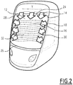
- a windshield assembly 10 for a vehicle is shown in the figures. figures 1 and 2 .
- the vertical direction Z is defined below as the perpendicular to the running plane of the corresponding vehicle.
- the transverse Y and longitudinal X directions are defined perpendicular to the vertical direction Z in the usual direction for a vehicle.
- Such an assembly does not have a windshield wiper.
- the assembly 10 is, for example, symmetrical with respect to a median plane parallel to the longitudinal X and vertical Z directions.
- the assembly 10 includes a windshield 12, a first air injection system 14 and a heating network 16.
- the assembly 10 further comprises here a second air injection system 18.
- the windshield 12 is designed to extend to the front of a vehicle or to one end of the vehicle in the case of a two-way traffic vehicle.
- the vehicle is for example a tram.
- the vehicle is a bus or a train, such as a low-speed train, for example of the Regional Express Transport (TER) network.
- TER Regional Express Transport
- the windshield 12 has an interior surface 20 intended to extend towards the interior of the vehicle and an exterior surface 22 intended to extend toward the exterior of the vehicle.
- the windshield 12 has an upper edge 24 and a lower edge 26.
- the windshield 12 also has two side edges 28, 30.
- Each side edge 28, 30 connects the upper edge 24 and the lower edge 26.
- the side edges 28, 30 are opposite in the transverse direction Y.
- the windshield 12 forms an angle of inclination ⁇ with the vertical direction Z, the angle of inclination being less than 40 °.
- the direction of inclination I is defined as a direction included in a plane perpendicular to the transverse direction Y and having with the vertical direction Z an angle equal to the angle of inclination a.
- the lower edge 26 and the upper edge 24 are opposite in the direction of inclination I.
- the windshield 12 is inclined such that the outer surface 22 faces upwards.
- the windshield 12 has a main extension plane.
- the main extension plane is here parallel to the transverse direction Y.
- the angle of inclination ⁇ is equal to the acute angle formed between the vertical direction Z and the main extension plane.
- the main extension plane here intersects with the lower edge 26 and the upper edge 24. More particularly, the main extension plane comprises the lower edge 26 and the upper edge 24 in the case of lower 26 and upper edges 24. right.
- the windshield 12 has a visibility zone 32.
- the visibility zone 32 corresponds, for example, to a zone of the windshield 12 through which a driver of the vehicle is made to look.
- the visibility zone 32 of the windshield 12 is, for example, defined according to the criteria of the STRMTG GUIDE: SAFETY OF DRIVING STATIONS OF TRAMWAYS in the case of a set of tram windshields.
- the exterior surface 22 is provided with a hydrophobic coating 34. More particularly, the entire exterior surface 22 is coated with the hydrophobic coating 34 in the visibility zone 32.
- the hydrophobic coating 34 is, for example, an AQUACONTROL ® coating marketed by Sekurit for Saint-Gobain.
- the hydrophobic coating 34 facilitates the sliding of water on the windshield, at least in the visibility zone 32, and prevents soiling.
- the first air injection system 14 is able to blow air.
- the first air injection system 14 has, for example, at least one activated state in which it blows air and a deactivated state in which it does not blow air.
- the first air injection system 14 blows, for example, continuously, more particularly when it is activated.
- the first air injection system 14 has several activated states corresponding to different speeds and / or orientations of the blown air.
- the first air injection system 14 extends along the upper edge 24 of the windshield 12. More particularly, the first air injection system 14 extends over the entire upper edge 24 of the windshield. windshield 12.
- the first air injection system 14 is arranged to blow air towards the lower edge 26.
- the direction of the air blown by the first air injection system 14 is inclined at an angle of less than 10 ° relative to the outer surface 22 of the windshield 12, for example relative to the extension plane main windshield. More particularly, the blown air has an inclination of between 0 ° and 10 °, the inclination being such that the air blown by the first air injection system approaches the windshield 12 during its ejection.
- the direction of the air blown by the first air injection system 14 is also here parallel to the side edges 28, 30 of the windshield 12 to within 5 °.
- the air flow blown by the first air injection system 14 has, for example, a speed of between 100 km / h and 300 km / h.
- the air flow blown by the first air injection system 14 allows water to be evacuated from the windshield 12.
- the second air injection system 18 is able to blow air.
- the second air injection system 18 has, for example, at least one activated state in which it blows air and a deactivated state in which it does not blow air.
- the second air injection system 18 blows, for example, continuously, more particularly when it is activated.
- the second air injection system 18 has several activated states corresponding to different speeds and / or orientations of the blown air.
- the second air injection system 18 extends along the two lateral edges 28, 30 of the windshield 12. More particularly, the second air injection system 18 extends over at least 50% of the area. each of the two side edges of the windshield 12.
- the second air injection system is arranged to blow air towards the lower edge 26.
- the direction of the air blown by the second air injection system 18 forms an angle with the lower edge 26 of between 30 ° and 60 °.
- the direction of the air blown by the second air injection system 18 is inclined at an angle of less than 10 ° relative to the outer surface 22 of the windshield 12, for example relative to the extension plane main windshield. More particularly, the blown air has an inclination of between 0 ° and 10 °, the inclination being such that the air blown by the second air injection system 18 approaches the windshield 12 during its ejection.
- the direction of the air blown by the second air injection system 18 is oriented towards a median plane of the windshield in the transverse direction Y.
- the air blown by the second air injection system 18 from each side edge 28, 30 forms a respective given angle with the transverse direction Y, the given angle being constant for each side edge. 28, 30.
- the air is directed in the direction of the median plane.
- the respective given angle is, for example, between 30 ° and 60 °.
- the air blown by the second air injection system 18 from each side edge 28, 30 is oriented in the transverse direction Y and the direction of inclination I towards the middle of the lower edge 26. .
- the air flow blown by the second air injection system 18 has, for example, a speed of between 100 km / h and 300 km / h.
- the flow of air blown by the second air injection system 18 assists in the evacuation of water from the windshield 12 by the flow of air blown by the first air injection system 14.
- the heating network 16 is able to heat said windshield 12.
- the heating network 16 is able to heat the whole of the visibility zone 32.
- the heating network 16 has, for example, at least one activated state in which it heats the windshield and a deactivated state in which it does not heat the windshield.
- the heating network 16 is, for example, able to maintain the windshield at a given heating temperature, more particularly when it is activated. Said given heating temperature is, for example, between 20 ° and 6 ° C.
- the network heater is particularly suitable for bringing the windshield to a temperature of 12 ° C after 4 min.
- the heating network 16 has several activated states corresponding to different heating temperatures.
- the heating network 16 is integrated into the windshield 12.
- the windshield 12 comprises, for example, at least two layers of glass, the heating network 16 comprising a network of electric wires arranged between two of the layers of glass.
- the heating network 16 prevents the formation of ice or snow on the windshield 12 and allows its transformation into liquid water, the evacuation of which is carried out by the first air injection system 14.
- the assembly also has no air injection system arranged along the lower edge of the windshield and capable of blowing air.
- Such an assembly is particularly advantageous in the case of a vehicle having a windshield exhibiting a slight inclination with the vertical and traveling at a speed of less than 100 km / h, for example for a tram, bus, coach, TER or boat.
- a windshield assembly according to the invention therefore makes it possible to evacuate all the bad weather such as rain, ice or snow, thanks to the combination of the heating network and the first air injection system.
- the second air injection system assists in the evacuation of water.
- the hydrophobic coating facilitates the sliding of water on the windshield and prevents certain possible soiling.
- such an assembly is able to operate continuously and constantly over time, unlike a wiper which has a wiping cycle. This makes it possible in particular to avoid having a portion of the windshield through which it is difficult to look in the event of very bad weather when the wiper sweeps another portion.
Landscapes
- Engineering & Computer Science (AREA)
- Mechanical Engineering (AREA)
- Air-Conditioning For Vehicles (AREA)
- Automobile Manufacture Line, Endless Track Vehicle, Trailer (AREA)
- Injection Moulding Of Plastics Or The Like (AREA)
Abstract
Description
- La présente invention concerne un ensemble de pare-brise pour véhicule.
- Pour permettre une bonne visibilité à travers le pare-brise, y compris en cas d'averse, il est usuellement prévu un ou plusieurs bras et balais d'essuie-glace.
- Cependant, la présence d'essuie-glace présente divers désavantages.
- Cela offre notamment des possibilités de prise, de sorte qu'une personne est susceptible de s'y accrocher, et ainsi se faire porter par le véhicule correspondant. Une telle pratique est particulièrement dangereuse.
- Par ailleurs, les bras d'essuie-glace forment une surface agressive et dangereuse sensiblement à la hauteur de la tête en cas de choc avec un piéton.
- En outre, les bras et balais d'essuie-glace réduisent, d'une part, la zone de visibilité du conducteur et, d'autre part, couvrent une zone d'essuyage limitée par rapport à la surface du pare-brise.
- Un objet de l'invention est donc de proposer un ensemble pour véhicule comprenant un pare-brise dépourvu d'essuie-glace et permettant une bonne visibilité y compris en cas d'averse.
- A cet effet, l'invention a pour objet un ensemble pour véhicule comprenant un pare-brise dépourvu d'essuie-glace, dans lequel, un premier système d'injection d'air et un réseau chauffant, le premier système d'injection d'air s'étendant le long du bord supérieur du pare-brise, le premier système d'injection d'air étant agencé pour souffler de l'air en direction du bord inférieur, le réseau chauffant étant apte à chauffer ledit pare-brise.
- Le premier système d'injection d'air assure notamment l'évacuation d'eau éventuellement présente sur le pare-brise. Le réseau chauffant prévient la formation de glace ou de neige sur le pare-brise et, le cas échéant, permet sa transformation en eau liquide dont l'évacuation est réalisée par le premier système d'injection d'air.
- L'ensemble peut en outre présenter une ou plusieurs des caractéristiques ci-dessous, considérées individuellement ou selon toutes les combinaisons techniquement possibles :
- le premier système d'injection d'air s'étend sur l'ensemble du bord supérieur du pare-brise,
- le pare-brise présente une zone de visibilité, le réseau chauffant étant apte à chauffer l'ensemble de la zone de visibilité,
- le réseau chauffant est intégré au pare-brise,
- le pare-brise comprend deux bords latéraux, l'ensemble comprenant un deuxième système d'injection d'air s'étendant le long des deux bords latéraux du pare-brise, le deuxième système d'injection d'air étant agencé pour souffler de l'air en direction du bord inférieur,
- le pare-brise présente une surface extérieure, la surface extérieure étant pourvue d'un revêtement hydrophobe,
- le pare-brise présente une zone de visibilité, l'ensemble de la surface extérieure étant revêtu par le revêtement hydrophobe dans la zone de visibilité,
- le pare-brise forme un angle inférieur à 40° avec une direction verticale
- l'ensemble est dépourvu d'essuie-glaces et/ou de système d'injection d'air apte à souffler de l'air et agencé le long du bord inférieur du pare-brise.
- L'invention concerne en outre un véhicule, notamment un tramway, comprenant un ensemble tel que décrit précédemment.
- D'autres caractéristiques et avantages de l'invention apparaîtront à la lecture de la description qui suit de modes de réalisation de l'invention, donnée à titre d'exemple uniquement et en référence aux dessins dans lesquels :
- [
Fig 1 ] lafigure 1 est une vue schématique en coupe de côté d'un véhicule comprenant un ensemble de pare-brise selon un mode de réalisation de l'invention, et - [
Fig 2 ] lafigure 2 est une vue schématique en perspective de trois-quarts face de l'ensemble de lafigure 1 . - Un ensemble 10 de pare-brise pour véhicule selon un mode de réalisation de l'invention est représenté sur les
figures 1 et2 . - La direction verticale Z est définie pour la suite comme la perpendiculaire du plan de roulement du véhicule correspondant. Les directions transversale Y et longitudinale X sont définies perpendiculairement à la direction verticale Z selon le sens usuel pour un véhicule.
- On entend par « inférieur » et « supérieur » les sens usuels par rapport à la direction verticale Z telle que définie ci-dessus.
- Un tel ensemble est dépourvu d'essuie-glace.
- L'ensemble 10 est, par exemple, symétrique par rapport à un plan médian parallèle aux directions longitudinale X et verticale Z.
- L'ensemble 10 comprend un pare-brise 12, un premier système d'injection d'air 14 et un réseau chauffant 16.
- L'ensemble 10 comprend en outre ici un deuxième système d'injection d'air 18.
- Le pare-brise 12 est prévu pour s'étendre à l'avant d'un véhicule ou à une extrémité du véhicule dans le cas d'un véhicule à double sens de circulation.
- Le véhicule est par exemple un tramway.
- Alternativement, le véhicule est un autobus ou un train, tel qu'un train à vitesse réduite, par exemple du réseau Transport express régional (TER).
- Le pare-brise 12 présente une surface intérieure 20 destinée à s'étendre vers l'intérieur du véhicule et une surface extérieure 22 destinée à s'étendre vers l'extérieur du véhicule.
- Le pare-brise 12 présente un bord supérieur 24 et un bord inférieur 26.
- Le pare-brise 12 présente en outre deux bords latéraux 28, 30.
- Chaque bord latéral 28, 30 relie le bord supérieur 24 et le bord inférieur 26.
- Les bords latéraux 28, 30 sont opposés selon la direction transversale Y.
- Le pare-brise 12 forme un angle d'inclinaison α avec la direction verticale Z, l'angle d'inclinaison étant inférieur à 40°.
- On définit la direction d'inclinaison I comme une direction comprise dans un plan perpendiculaire à la direction transversale Y et présentant avec la direction verticale Z un angle égal à l'angle d'inclinaison a.
- Le bord inférieur 26 et le bord supérieur 24 sont opposés selon la direction d'inclinaison I.
- Le pare-brise 12 est incliné tel que la surface extérieure 22 est orientée vers le haut.
- Dans le mode de réalisation représenté, le pare-brise 12 présente un plan d'extension principale. Le plan d'extension principale est ici parallèle à la direction transversale Y. L'angle d'inclinaison α est égal à l'angle aigu formé entre la direction verticale Z et le plan d'extension principale.
- Le plan d'extension principale entre ici en intersection avec le bord inférieur 26 et le bord supérieur 24. Plus particulièrement, le plan d'extension principale comprend le bord inférieur 26 et le bord supérieur 24 dans le cas de bords inférieur 26 et supérieur 24 droit.
- Le pare-brise 12 présente une zone de visibilité 32.
- La zone de visibilité 32 correspond, par exemple, à une zone du pare-brise 12 à travers laquelle un conducteur du véhicule est amené à regarder.
- La zone de visibilité 32 du pare-brise 12 est, par exemple, définie suivant les critère du GUIDE STRMTG : SECURITE DES POSTES DE CONDUITE DES TRAMWAYS dans le cas d'un ensemble de pare-brise de tramway.
- La surface extérieure 22 est pourvue d'un revêtement hydrophobe 34. Plus particulièrement, l'ensemble de la surface extérieure 22 est revêtu du revêtement hydrophobe 34 dans la zone de visibilité 32.
- Le revêtement hydrophobe 34 est, par exemple, un revêtement AQUACONTROL ® commercialisé par Sekurit pour Saint-Gobain.
- Le revêtement hydrophobe 34 facilite le glissement de l'eau sur le pare-brise, au moins dans la zone de visibilité 32, et prévient des salissures.
- Le premier système d'injection d'air 14 est apte à souffler de l'air.
- Le premier système d'injection d'air 14 présente, par exemple, au moins un état activé dans lequel il souffle de l'air et un état désactivé dans lequel il ne souffle pas d'air.
- Le premier système d'injection d'air 14 souffle, par exemple, en continu, plus particulièrement lorsqu'il est activé.
- Dans un mode de réalisation, le premier système d'injection d'air 14 présente plusieurs états activés correspondant à des vitesses et/ou des orientations différentes de l'air soufflé.
- Le premier système d'injection d'air 14 s'étend le long du bord supérieur 24 du pare-brise 12. Plus particulièrement, le premier système d'injection d'air 14 s'étend sur l'ensemble du bord supérieur 24 du pare-brise 12.
- Le premier système d'injection d'air 14 est agencé pour souffler de l'air en direction du bord inférieur 26.
- La direction de l'air soufflé par le premier système d'injection d'air 14 est incliné d'un angle inférieur à 10° par rapport à la surface extérieure 22 du pare-brise 12, par exemple par rapport au plan d'extension principale du pare-brise. Plus particulièrement, l'air soufflé présente une inclinaison comprise entre 0° et 10°, l'inclinaison étant telle que l'air soufflé par le premier système d'injection d'air se rapproche du pare-brise 12 pendant son éjection.
- La direction de l'air soufflé par le premier système d'injection d'air 14 est en outre ici parallèle aux bords latéraux 28, 30 du pare-brise 12 à 5° près.
- Le flux d'air soufflé par le premier système d'injection d'air 14 présente, par exemple, une vitesse comprise entre 100 km/h et 300 km/h.
- Le flux d'air soufflé par le premier système d'injection d'air 14 permet l'évacuation d'eau du pare-brise 12.
- Le deuxième système d'injection d'air 18 est apte à souffler de l'air.
- Le deuxième système d'injection d'air 18 présente, par exemple, au moins un état activé dans lequel il souffle de l'air et un état désactivé dans lequel il ne souffle pas d'air.
- Le deuxième système d'injection d'air 18 souffle, par exemple, en continu, plus particulièrement lorsqu'il est activé.
- Dans un mode de réalisation, le deuxième système d'injection d'air 18 présente plusieurs états activés correspondant à des vitesses et/ou des orientations différentes de l'air soufflé.
- Le deuxième système d'injection d'air 18 s'étend le long des deux bords latéraux 28, 30 du pare-brise 12. Plus particulièrement, le deuxième système d'injection d'air 18 s'étend sur au moins 50% de chacun des deux bords latéraux du pare-brise 12.
- Le deuxième système d'injection d'air est agencé pour souffler de l'air en direction du bord inférieur 26.
- Plus particulièrement, la direction de l'air soufflé par le deuxième système d'injection d'air 18 forme un angle avec le bord inférieur 26 comprise entre 30° et 60°.
- La direction de l'air soufflé par le deuxième système d'injection d'air 18 est incliné d'un angle inférieur à 10° par rapport à la surface extérieure 22 du pare-brise 12, par exemple par rapport au plan d'extension principale du pare-brise. Plus particulièrement, l'air soufflé présente une inclinaison comprise entre 0° et 10°, l'inclinaison étant telle que l'air soufflé par le deuxième système d'injection d'air 18 se rapproche du pare-brise 12 pendant son éjection.
- En outre, la direction de l'air soufflé par le deuxième système d'injection d'air 18 est orientée vers un plan médian du pare-brise selon la direction transversale Y.
- Dans le mode de réalisation représenté, l'air soufflé par le deuxième système d'injection d'air 18 depuis chaque bord latéral 28, 30 forme un angle donné respectif avec la direction transversale Y, l'angle donné étant constant pour chaque bord latéral 28, 30. L'air est orienté en direction du plan médian. L'angle donné respectif est, par exemple, compris entre 30° et 60°.
- Dans un mode de réalisation alternatif, l'air soufflé par le deuxième système d'injection d'air 18 depuis chaque bord latéral 28, 30 est orienté selon la direction transversale Y et la direction d'inclinaison I vers le milieu du bord inférieur 26.
- Le flux d'air soufflé par le deuxième système d'injection d'air 18 présente, par exemple, une vitesse comprise entre 100 km/h et 300 km/h.
- Le flux d'air soufflé par le deuxième système d'injection d'air 18 aide à l'évacuation de l'eau du pare-brise 12 par le flux d'air soufflé par le premier système d'injection d'air 14.
- Le réseau chauffant 16 est apte à chauffer ledit pare-brise 12.
- Plus particulièrement, le réseau chauffant 16 est apte à chauffer l'ensemble de la zone de visibilité 32.
- Le réseau chauffant 16 présente, par exemple, au moins un état activé dans lequel il chauffe le pare-brise et un état désactivé dans lequel il ne chauffe pas le pare-brise.
- Le réseau chauffant 16 est, par exemple, apte à maintenir le pare-brise à une température de chauffage donnée, plus particulièrement lorsqu'il est activé. Ladite température de chauffage donnée est par exemple, comprise entre 20° et 6°C. Le réseau chauffant est notamment apte à porter le pare-brise à une température de 12°C au bout de 4 min.
- Dans un mode de réalisation, le réseau chauffant 16 présente plusieurs états activés correspondant à des températures de chauffage différentes.
- Le réseau chauffant 16 est intégré au pare-brise 12.
- Le pare-brise 12 comprend, par exemple, au moins deux couches de verre, le réseau chauffant 16 comprenant un réseau de fils électriques agencés entre deux des couches de verre.
- Le réseau chauffant 16 prévient la formation de glace ou de neige sur le pare-brise 12 et permet sa transformation en eau liquide dont l'évacuation est réalisée par le premier système d'injection d'air 14.
- L'ensemble est en outre dépourvu de système d'injection d'air agencé le long du bord inférieur du pare-brise et apte à souffler de l'air.
- Un tel ensemble est particulièrement avantageux dans le cas d'un véhicule présentant un pare-brise présentant une faible inclinaison avec la verticale et circulant à une vitesse inférieure à 100km/h, par exemple pour un tramway, bus, autocar, TER ou bateau.
- Un ensemble de pare-brise selon l'invention permet donc d'évacuer l'ensemble des intempéries du type pluie, glace ou neige, grâce à la combinaison du réseau chauffant et du premier système d'injection d'air.
- Dans un mode de réalisation avantageux, le deuxième système d'injection d'air aide à l'évacuation d'eau.
- Dans un mode de réalisation avantageux, le revêtement hydrophobe facilite le glissement de l'eau sur le pare-brise et prévient certaines salissures éventuelles.
- Ainsi, la visibilité à travers le pare-brise est garantie, y compris en cas d'intempéries.
- L'absence d'essuie-glaces évite la présence de surface agressive en cas d'impact, la présence de prises pour des personnes souhaitant s'accrocher au véhicule, la présence de zones de visibilité morte dues à la présence ou au passage de l'essuie-glace dans la zone d'essuyage ou de zones à faible visibilité.
- En outre, un tel ensemble est apte à fonctionner de manière continue et constante dans le temps, contrairement à un essuie-glace qui présente un cycle de balayage. Cela permet notamment d'éviter d'avoir une portion du pare-brise à travers laquelle il est difficile de regarder en cas de très fortes intempéries lorsque l'essuie-glace balaie une autre portion.
Claims (9)
- Ensemble (10) de pare-brise pour véhicule, l'ensemble comprenant un pare-brise (12), le pare-brise (12) comprenant un bord supérieur (24) et un bord inférieur (26), l'ensemble (10) comprenant un premier système d'injection d'air (14) et un réseau chauffant (16), le premier système d'injection d'air (14) s'étendant le long du bord supérieur (24) du pare-brise (12), le premier système d'injection d'air (14) étant agencé pour souffler de l'air en direction du bord inférieur (26), le réseau chauffant (16) étant apte à chauffer ledit pare-brise (12), le réseau chauffant (16) étant intégré au pare-brise (12).
- Ensemble selon la revendication 1, dans lequel le premier système d'injection d'air (14) s'étend sur l'ensemble du bord supérieur (24) du pare-brise (12).
- Ensemble selon la revendication 1 ou 2, dans lequel le pare-brise (12) présente une zone de visibilité (32), le réseau chauffant (16) étant apte à chauffer l'ensemble de la zone de visibilité (32).
- Ensemble selon l'une quelconque des revendications 1 à 3, dans lequel le pare-brise (12) comprend deux bords latéraux (28, 30), l'ensemble comprenant un deuxième système d'injection d'air (18) s'étendant le long des deux bords latéraux (28, 30) du pare-brise, le deuxième système d'injection d'air (18) étant agencé pour souffler de l'air en direction du bord inférieur (26).
- Ensemble selon l'une quelconque des revendications 1 à 4, dans lequel le pare-brise (12) présente une surface extérieure (22), la surface extérieure (22) étant pourvue d'un revêtement hydrophobe (34).
- Ensemble selon la revendication 5, dans lequel le pare-brise (12) présente une zone de visibilité (32), l'ensemble de la surface extérieure (22) étant revêtu par le revêtement hydrophobe (34) dans la zone de visibilité (32).
- Ensemble selon l'une quelconque des revendications 1 à 6, dans lequel le pare-brise (12) forme un angle (a) inférieur à 40° avec une direction verticale (Z).
- Ensemble selon l'une quelconque des revendications 1 à 7, dépourvu d'essuie-glaces et/ou de système d'injection d'air apte à souffler de l'air et agencé le long du bord inférieur (26) du pare-brise (12).
- Véhicule, notamment tramway, comprenant un ensemble (10) selon l'une quelconque des revendications 1 à 8.
Applications Claiming Priority (1)
| Application Number | Priority Date | Filing Date | Title |
|---|---|---|---|
| FR2006456A FR3111603B1 (fr) | 2020-06-19 | 2020-06-19 | Ensemble de pare-brise pour véhicule dépourvu d’essuie-glace et véhicule associé |
Publications (2)
| Publication Number | Publication Date |
|---|---|
| EP3925837A1 true EP3925837A1 (fr) | 2021-12-22 |
| EP3925837B1 EP3925837B1 (fr) | 2025-04-09 |
Family
ID=72560801
Family Applications (1)
| Application Number | Title | Priority Date | Filing Date |
|---|---|---|---|
| EP21180344.0A Active EP3925837B1 (fr) | 2020-06-19 | 2021-06-18 | Ensemble de pare-brise pour véhicule dépourvu d'essuie-glace et véhicule associé |
Country Status (3)
| Country | Link |
|---|---|
| EP (1) | EP3925837B1 (fr) |
| ES (1) | ES3032401T3 (fr) |
| FR (1) | FR3111603B1 (fr) |
Citations (7)
| Publication number | Priority date | Publication date | Assignee | Title |
|---|---|---|---|---|
| FR1003943A (fr) * | 1949-10-29 | 1952-03-24 | Essuie-glace pour véhicules | |
| BE523394A (fr) * | 1953-10-09 | 1953-10-31 | Bodet-Marechal R | Dispositif remplacant les essuie-glaces des vehicules routiers |
| CH337737A (de) * | 1955-08-15 | 1959-04-15 | Zogg Andreas Jun | Verfahren zum Reinigen von Scheiben und Vorrichtung zur Durchführung des Verfahrens |
| GB2341787A (en) * | 1998-09-24 | 2000-03-29 | Mohamad Alame | Air jet windscreen cleaners |
| US6273488B1 (en) * | 1999-05-03 | 2001-08-14 | Guardian Industries Corporation | System and method for removing liquid from rear window of a vehicle |
| US20130075383A1 (en) * | 2011-09-23 | 2013-03-28 | Samsung Electro-Mechanics Co., Ltd. | Transparent heating device |
| JP2017212148A (ja) * | 2016-05-26 | 2017-11-30 | 日本板硝子株式会社 | ウインドシールド |
Family Cites Families (5)
| Publication number | Priority date | Publication date | Assignee | Title |
|---|---|---|---|---|
| CN1069237A (zh) * | 1992-03-28 | 1993-02-24 | 徐基盛 | 气帘式除霜解冻扫雨器 |
| DE10012004A1 (de) * | 2000-03-11 | 2001-09-27 | Bosch Gmbh Robert | Einrichtung zum Sauberhalten optischer Elemente in Kraftfahrzeugen, insbesondere von Sensor- oder Kamera-Abdeckungen |
| CN2452831Y (zh) * | 2000-10-08 | 2001-10-10 | 刘采联 | 汽车挡风玻璃雨雪风刮器 |
| DE102015210469A1 (de) * | 2015-06-08 | 2016-12-08 | Bombardier Transportation Gmbh | Anordnung zum optischen Erfassen einer Umgebung eines Fahrzeugs, insbesondere eines Schienenfahrzeugs oder eines Busses, Fahrzeug mit der Anordnung und Verfahren zum Betreiben der Anordnung |
| JP7180305B2 (ja) * | 2018-11-19 | 2022-11-30 | トヨタ自動車株式会社 | ウィンドウガラス加熱装置 |
-
2020
- 2020-06-19 FR FR2006456A patent/FR3111603B1/fr active Active
-
2021
- 2021-06-18 EP EP21180344.0A patent/EP3925837B1/fr active Active
- 2021-06-18 ES ES21180344T patent/ES3032401T3/es active Active
Patent Citations (7)
| Publication number | Priority date | Publication date | Assignee | Title |
|---|---|---|---|---|
| FR1003943A (fr) * | 1949-10-29 | 1952-03-24 | Essuie-glace pour véhicules | |
| BE523394A (fr) * | 1953-10-09 | 1953-10-31 | Bodet-Marechal R | Dispositif remplacant les essuie-glaces des vehicules routiers |
| CH337737A (de) * | 1955-08-15 | 1959-04-15 | Zogg Andreas Jun | Verfahren zum Reinigen von Scheiben und Vorrichtung zur Durchführung des Verfahrens |
| GB2341787A (en) * | 1998-09-24 | 2000-03-29 | Mohamad Alame | Air jet windscreen cleaners |
| US6273488B1 (en) * | 1999-05-03 | 2001-08-14 | Guardian Industries Corporation | System and method for removing liquid from rear window of a vehicle |
| US20130075383A1 (en) * | 2011-09-23 | 2013-03-28 | Samsung Electro-Mechanics Co., Ltd. | Transparent heating device |
| JP2017212148A (ja) * | 2016-05-26 | 2017-11-30 | 日本板硝子株式会社 | ウインドシールド |
Also Published As
| Publication number | Publication date |
|---|---|
| ES3032401T3 (en) | 2025-07-18 |
| FR3111603A1 (fr) | 2021-12-24 |
| FR3111603B1 (fr) | 2022-08-05 |
| EP3925837B1 (fr) | 2025-04-09 |
Similar Documents
| Publication | Publication Date | Title |
|---|---|---|
| FR2648413A1 (fr) | Deflecteur a guidage de flux d'air | |
| FR2791025A1 (fr) | Vehicule ferroviaire a extremite profilee | |
| FR3056502A1 (fr) | Retroviseur exterieur de vehicule automobile | |
| EP3925837B1 (fr) | Ensemble de pare-brise pour véhicule dépourvu d'essuie-glace et véhicule associé | |
| EP0436519B1 (fr) | Dispositif de climatisation, notamment pour véhicules ferroviaires | |
| FR2918329A1 (fr) | Ecope de refroidissement pour vehicule automobile | |
| FR2502230A1 (fr) | Dispositif de montage de vitres, notamment pour vehicules automobiles | |
| FR2695607A1 (fr) | Raclette d'essuyage pour un balai d'essuie-glace de véhicule automobile comportant une rampe d'alimentation et d'aspersion en liquide de lavage. | |
| FR2534858A1 (fr) | Motif de bande de roulement pour pneumatique radial pour lourdes charges, par exemple pour metro sur pneus | |
| FR2505754A1 (fr) | Balai d'essuie-glace, en particulier pour vehicule automobile | |
| FR2689836A1 (fr) | Dispositif d'éssuie-glace incorporant un déflecteur à lame souple amovible. | |
| FR2563173A1 (fr) | Structure de traverse arriere superieure de caisse de vehicule automobile | |
| FR2681821A1 (fr) | Dispositif reflechissant associe a la partie arriere d'un vehicule automobile. | |
| FR2893567A1 (fr) | Retroviseur comprenant un boitier pourvu d'ondulations | |
| FR2661146A1 (fr) | Essuie-glace. | |
| FR2591951A1 (fr) | Deflecteur d'air, notamment pour equiper la portiere d'une automobile | |
| FR2886912A1 (fr) | Procede de fabrication de vehicules par fixation d'un pavillon de toit a la caisse | |
| EP2668052A1 (fr) | Vitre pour vehicule, ensemble de vitrage comprenant une telle vitre et vehicule comprenant un tel ensemble de vitrage. | |
| FR2998221A1 (fr) | Vitre, notamment pare-brise de vehicule automobile | |
| FR2674480A1 (fr) | Deflecteur d'air a ailerons, notamment pour vehicule automobile. | |
| FR2476569A1 (fr) | Essuie-glace pour vehicules automobiles | |
| WO1984000933A1 (fr) | Dispositif pour ameliorer la stabilite d'un vehicule en mouvement | |
| EP3650303B1 (fr) | Voiture de véhicule ferroviaire à dispositif d'occultation d'ouverture vitrée | |
| FR2846615A1 (fr) | Raclette d'essuie-glace | |
| EP3556616A1 (fr) | Deflecteur d'air destine a un balai d'essuyage |
Legal Events
| Date | Code | Title | Description |
|---|---|---|---|
| PUAI | Public reference made under article 153(3) epc to a published international application that has entered the european phase |
Free format text: ORIGINAL CODE: 0009012 |
|
| STAA | Information on the status of an ep patent application or granted ep patent |
Free format text: STATUS: THE APPLICATION HAS BEEN PUBLISHED |
|
| STAA | Information on the status of an ep patent application or granted ep patent |
Free format text: STATUS: REQUEST FOR EXAMINATION WAS MADE |
|
| AK | Designated contracting states |
Kind code of ref document: A1 Designated state(s): AL AT BE BG CH CY CZ DE DK EE ES FI FR GB GR HR HU IE IS IT LI LT LU LV MC MK MT NL NO PL PT RO RS SE SI SK SM TR |
|
| B565 | Issuance of search results under rule 164(2) epc |
Effective date: 20211109 |
|
| 17P | Request for examination filed |
Effective date: 20211130 |
|
| RBV | Designated contracting states (corrected) |
Designated state(s): AL AT BE BG CH CY CZ DE DK EE ES FI FR GB GR HR HU IE IS IT LI LT LU LV MC MK MT NL NO PL PT RO RS SE SI SK SM TR |
|
| STAA | Information on the status of an ep patent application or granted ep patent |
Free format text: STATUS: EXAMINATION IS IN PROGRESS |
|
| 17Q | First examination report despatched |
Effective date: 20230504 |
|
| P01 | Opt-out of the competence of the unified patent court (upc) registered |
Effective date: 20230823 |
|
| RAP1 | Party data changed (applicant data changed or rights of an application transferred) |
Owner name: ALSTOM HOLDINGS |
|
| GRAP | Despatch of communication of intention to grant a patent |
Free format text: ORIGINAL CODE: EPIDOSNIGR1 |
|
| STAA | Information on the status of an ep patent application or granted ep patent |
Free format text: STATUS: GRANT OF PATENT IS INTENDED |
|
| INTG | Intention to grant announced |
Effective date: 20241104 |
|
| GRAS | Grant fee paid |
Free format text: ORIGINAL CODE: EPIDOSNIGR3 |
|
| GRAA | (expected) grant |
Free format text: ORIGINAL CODE: 0009210 |
|
| STAA | Information on the status of an ep patent application or granted ep patent |
Free format text: STATUS: THE PATENT HAS BEEN GRANTED |
|
| AK | Designated contracting states |
Kind code of ref document: B1 Designated state(s): AL AT BE BG CH CY CZ DE DK EE ES FI FR GB GR HR HU IE IS IT LI LT LU LV MC MK MT NL NO PL PT RO RS SE SI SK SM TR |
|
| REG | Reference to a national code |
Ref country code: GB Ref legal event code: FG4D Free format text: NOT ENGLISH |
|
| REG | Reference to a national code |
Ref country code: CH Ref legal event code: EP |
|
| REG | Reference to a national code |
Ref country code: DE Ref legal event code: R096 Ref document number: 602021028783 Country of ref document: DE |
|
| REG | Reference to a national code |
Ref country code: IE Ref legal event code: FG4D Free format text: LANGUAGE OF EP DOCUMENT: FRENCH |
|
| PGFP | Annual fee paid to national office [announced via postgrant information from national office to epo] |
Ref country code: DE Payment date: 20250618 Year of fee payment: 5 |
|
| PGFP | Annual fee paid to national office [announced via postgrant information from national office to epo] |
Ref country code: FR Payment date: 20250627 Year of fee payment: 5 |
|
| REG | Reference to a national code |
Ref country code: ES Ref legal event code: FG2A Ref document number: 3032401 Country of ref document: ES Kind code of ref document: T3 Effective date: 20250718 |
|
| PGFP | Annual fee paid to national office [announced via postgrant information from national office to epo] |
Ref country code: AT Payment date: 20250721 Year of fee payment: 5 |
|
| REG | Reference to a national code |
Ref country code: NL Ref legal event code: MP Effective date: 20250409 |
|
| PG25 | Lapsed in a contracting state [announced via postgrant information from national office to epo] |
Ref country code: NL Free format text: LAPSE BECAUSE OF FAILURE TO SUBMIT A TRANSLATION OF THE DESCRIPTION OR TO PAY THE FEE WITHIN THE PRESCRIBED TIME-LIMIT Effective date: 20250409 |
|
| PG25 | Lapsed in a contracting state [announced via postgrant information from national office to epo] |
Ref country code: PT Free format text: LAPSE BECAUSE OF FAILURE TO SUBMIT A TRANSLATION OF THE DESCRIPTION OR TO PAY THE FEE WITHIN THE PRESCRIBED TIME-LIMIT Effective date: 20250811 Ref country code: FI Free format text: LAPSE BECAUSE OF FAILURE TO SUBMIT A TRANSLATION OF THE DESCRIPTION OR TO PAY THE FEE WITHIN THE PRESCRIBED TIME-LIMIT Effective date: 20250409 |
|
| PGFP | Annual fee paid to national office [announced via postgrant information from national office to epo] |
Ref country code: ES Payment date: 20250731 Year of fee payment: 5 |
|
| REG | Reference to a national code |
Ref country code: LT Ref legal event code: MG9D |
|
| PG25 | Lapsed in a contracting state [announced via postgrant information from national office to epo] |
Ref country code: GR Free format text: LAPSE BECAUSE OF FAILURE TO SUBMIT A TRANSLATION OF THE DESCRIPTION OR TO PAY THE FEE WITHIN THE PRESCRIBED TIME-LIMIT Effective date: 20250710 Ref country code: NO Free format text: LAPSE BECAUSE OF FAILURE TO SUBMIT A TRANSLATION OF THE DESCRIPTION OR TO PAY THE FEE WITHIN THE PRESCRIBED TIME-LIMIT Effective date: 20250709 |
|
| PG25 | Lapsed in a contracting state [announced via postgrant information from national office to epo] |
Ref country code: PL Free format text: LAPSE BECAUSE OF FAILURE TO SUBMIT A TRANSLATION OF THE DESCRIPTION OR TO PAY THE FEE WITHIN THE PRESCRIBED TIME-LIMIT Effective date: 20250409 |
|
| PGFP | Annual fee paid to national office [announced via postgrant information from national office to epo] |
Ref country code: IT Payment date: 20250730 Year of fee payment: 5 |
|
| PG25 | Lapsed in a contracting state [announced via postgrant information from national office to epo] |
Ref country code: BG Free format text: LAPSE BECAUSE OF FAILURE TO SUBMIT A TRANSLATION OF THE DESCRIPTION OR TO PAY THE FEE WITHIN THE PRESCRIBED TIME-LIMIT Effective date: 20250409 |
|
| PG25 | Lapsed in a contracting state [announced via postgrant information from national office to epo] |
Ref country code: HR Free format text: LAPSE BECAUSE OF FAILURE TO SUBMIT A TRANSLATION OF THE DESCRIPTION OR TO PAY THE FEE WITHIN THE PRESCRIBED TIME-LIMIT Effective date: 20250409 |
|
| PGFP | Annual fee paid to national office [announced via postgrant information from national office to epo] |
Ref country code: CH Payment date: 20250701 Year of fee payment: 5 |
|
| PG25 | Lapsed in a contracting state [announced via postgrant information from national office to epo] |
Ref country code: RS Free format text: LAPSE BECAUSE OF FAILURE TO SUBMIT A TRANSLATION OF THE DESCRIPTION OR TO PAY THE FEE WITHIN THE PRESCRIBED TIME-LIMIT Effective date: 20250709 |
|
| PGFP | Annual fee paid to national office [announced via postgrant information from national office to epo] |
Ref country code: CZ Payment date: 20250610 Year of fee payment: 5 |
|
| PG25 | Lapsed in a contracting state [announced via postgrant information from national office to epo] |
Ref country code: IS Free format text: LAPSE BECAUSE OF FAILURE TO SUBMIT A TRANSLATION OF THE DESCRIPTION OR TO PAY THE FEE WITHIN THE PRESCRIBED TIME-LIMIT Effective date: 20250809 |
|
| PG25 | Lapsed in a contracting state [announced via postgrant information from national office to epo] |
Ref country code: LV Free format text: LAPSE BECAUSE OF FAILURE TO SUBMIT A TRANSLATION OF THE DESCRIPTION OR TO PAY THE FEE WITHIN THE PRESCRIBED TIME-LIMIT Effective date: 20250409 |
|
| REG | Reference to a national code |
Ref country code: DE Ref legal event code: R097 Ref document number: 602021028783 Country of ref document: DE |
|
| PG25 | Lapsed in a contracting state [announced via postgrant information from national office to epo] |
Ref country code: DK Free format text: LAPSE BECAUSE OF FAILURE TO SUBMIT A TRANSLATION OF THE DESCRIPTION OR TO PAY THE FEE WITHIN THE PRESCRIBED TIME-LIMIT Effective date: 20250409 Ref country code: SM Free format text: LAPSE BECAUSE OF FAILURE TO SUBMIT A TRANSLATION OF THE DESCRIPTION OR TO PAY THE FEE WITHIN THE PRESCRIBED TIME-LIMIT Effective date: 20250409 |
|
| PG25 | Lapsed in a contracting state [announced via postgrant information from national office to epo] |
Ref country code: EE Free format text: LAPSE BECAUSE OF FAILURE TO SUBMIT A TRANSLATION OF THE DESCRIPTION OR TO PAY THE FEE WITHIN THE PRESCRIBED TIME-LIMIT Effective date: 20250409 |
|
| PG25 | Lapsed in a contracting state [announced via postgrant information from national office to epo] |
Ref country code: SK Free format text: LAPSE BECAUSE OF FAILURE TO SUBMIT A TRANSLATION OF THE DESCRIPTION OR TO PAY THE FEE WITHIN THE PRESCRIBED TIME-LIMIT Effective date: 20250409 Ref country code: RO Free format text: LAPSE BECAUSE OF FAILURE TO SUBMIT A TRANSLATION OF THE DESCRIPTION OR TO PAY THE FEE WITHIN THE PRESCRIBED TIME-LIMIT Effective date: 20250409 |
|
| PG25 | Lapsed in a contracting state [announced via postgrant information from national office to epo] |
Ref country code: MC Free format text: LAPSE BECAUSE OF FAILURE TO SUBMIT A TRANSLATION OF THE DESCRIPTION OR TO PAY THE FEE WITHIN THE PRESCRIBED TIME-LIMIT Effective date: 20250409 |
|
| PLBE | No opposition filed within time limit |
Free format text: ORIGINAL CODE: 0009261 |
|
| STAA | Information on the status of an ep patent application or granted ep patent |
Free format text: STATUS: NO OPPOSITION FILED WITHIN TIME LIMIT |
|
| PG25 | Lapsed in a contracting state [announced via postgrant information from national office to epo] |
Ref country code: LU Free format text: LAPSE BECAUSE OF NON-PAYMENT OF DUE FEES Effective date: 20250618 |
|
| REG | Reference to a national code |
Ref country code: CH Ref legal event code: L10 Free format text: ST27 STATUS EVENT CODE: U-0-0-L10-L00 (AS PROVIDED BY THE NATIONAL OFFICE) Effective date: 20260218 |
|
| REG | Reference to a national code |
Ref country code: BE Ref legal event code: MM Effective date: 20250630 |
|
| 26N | No opposition filed |
Effective date: 20260112 |
|
| GBPC | Gb: european patent ceased through non-payment of renewal fee |
Effective date: 20250709 |
|
| PG25 | Lapsed in a contracting state [announced via postgrant information from national office to epo] |
Ref country code: GB Free format text: LAPSE BECAUSE OF NON-PAYMENT OF DUE FEES Effective date: 20250709 |
|
| PG25 | Lapsed in a contracting state [announced via postgrant information from national office to epo] |
Ref country code: IE Free format text: LAPSE BECAUSE OF NON-PAYMENT OF DUE FEES Effective date: 20250618 |
|
| PG25 | Lapsed in a contracting state [announced via postgrant information from national office to epo] |
Ref country code: BE Free format text: LAPSE BECAUSE OF NON-PAYMENT OF DUE FEES Effective date: 20250630 |