EP3925762A2 - Facer zur fusion der enden von polyolefinrohren - Google Patents
Facer zur fusion der enden von polyolefinrohren Download PDFInfo
- Publication number
- EP3925762A2 EP3925762A2 EP21190708.4A EP21190708A EP3925762A2 EP 3925762 A2 EP3925762 A2 EP 3925762A2 EP 21190708 A EP21190708 A EP 21190708A EP 3925762 A2 EP3925762 A2 EP 3925762A2
- Authority
- EP
- European Patent Office
- Prior art keywords
- facer
- drive unit
- guide rail
- output shaft
- blade
- Prior art date
- Legal status (The legal status is an assumption and is not a legal conclusion. Google has not performed a legal analysis and makes no representation as to the accuracy of the status listed.)
- Granted
Links
Images





Classifications
-
- B—PERFORMING OPERATIONS; TRANSPORTING
- B26—HAND CUTTING TOOLS; CUTTING; SEVERING
- B26D—CUTTING; DETAILS COMMON TO MACHINES FOR PERFORATING, PUNCHING, CUTTING-OUT, STAMPING-OUT OR SEVERING
- B26D1/00—Cutting through work characterised by the nature or movement of the cutting member or particular materials not otherwise provided for; Apparatus or machines therefor; Cutting members therefor
- B26D1/01—Cutting through work characterised by the nature or movement of the cutting member or particular materials not otherwise provided for; Apparatus or machines therefor; Cutting members therefor involving a cutting member which does not travel with the work
- B26D1/12—Cutting through work characterised by the nature or movement of the cutting member or particular materials not otherwise provided for; Apparatus or machines therefor; Cutting members therefor involving a cutting member which does not travel with the work having a cutting member moving about an axis
- B26D1/25—Cutting through work characterised by the nature or movement of the cutting member or particular materials not otherwise provided for; Apparatus or machines therefor; Cutting members therefor involving a cutting member which does not travel with the work having a cutting member moving about an axis with a non-circular cutting member
- B26D1/26—Cutting through work characterised by the nature or movement of the cutting member or particular materials not otherwise provided for; Apparatus or machines therefor; Cutting members therefor involving a cutting member which does not travel with the work having a cutting member moving about an axis with a non-circular cutting member moving about an axis substantially perpendicular to the line of cut
- B26D1/28—Cutting through work characterised by the nature or movement of the cutting member or particular materials not otherwise provided for; Apparatus or machines therefor; Cutting members therefor involving a cutting member which does not travel with the work having a cutting member moving about an axis with a non-circular cutting member moving about an axis substantially perpendicular to the line of cut and rotating continuously in one direction during cutting
-
- B—PERFORMING OPERATIONS; TRANSPORTING
- B23—MACHINE TOOLS; METAL-WORKING NOT OTHERWISE PROVIDED FOR
- B23B—TURNING; BORING
- B23B5/00—Turning-machines or devices specially adapted for particular work; Accessories specially adapted therefor
- B23B5/08—Turning-machines or devices specially adapted for particular work; Accessories specially adapted therefor for turning axles, bars, rods, tubes, rolls, i.e. shaft-turning lathes, roll lathes; Centreless turning
-
- B—PERFORMING OPERATIONS; TRANSPORTING
- B23—MACHINE TOOLS; METAL-WORKING NOT OTHERWISE PROVIDED FOR
- B23B—TURNING; BORING
- B23B5/00—Turning-machines or devices specially adapted for particular work; Accessories specially adapted therefor
- B23B5/16—Turning-machines or devices specially adapted for particular work; Accessories specially adapted therefor for bevelling, chamfering, or deburring the ends of bars or tubes
-
- B—PERFORMING OPERATIONS; TRANSPORTING
- B26—HAND CUTTING TOOLS; CUTTING; SEVERING
- B26D—CUTTING; DETAILS COMMON TO MACHINES FOR PERFORATING, PUNCHING, CUTTING-OUT, STAMPING-OUT OR SEVERING
- B26D3/00—Cutting work characterised by the nature of the cut made; Apparatus therefor
- B26D3/16—Cutting rods or tubes transversely
- B26D3/166—Trimming tube-ends
-
- B—PERFORMING OPERATIONS; TRANSPORTING
- B26—HAND CUTTING TOOLS; CUTTING; SEVERING
- B26D—CUTTING; DETAILS COMMON TO MACHINES FOR PERFORATING, PUNCHING, CUTTING-OUT, STAMPING-OUT OR SEVERING
- B26D7/00—Details of apparatus for cutting, cutting-out, stamping-out, punching, perforating, or severing by means other than cutting
- B26D7/0006—Means for guiding the cutter
-
- B—PERFORMING OPERATIONS; TRANSPORTING
- B26—HAND CUTTING TOOLS; CUTTING; SEVERING
- B26D—CUTTING; DETAILS COMMON TO MACHINES FOR PERFORATING, PUNCHING, CUTTING-OUT, STAMPING-OUT OR SEVERING
- B26D7/00—Details of apparatus for cutting, cutting-out, stamping-out, punching, perforating, or severing by means other than cutting
- B26D7/01—Means for holding or positioning work
-
- B—PERFORMING OPERATIONS; TRANSPORTING
- B26—HAND CUTTING TOOLS; CUTTING; SEVERING
- B26D—CUTTING; DETAILS COMMON TO MACHINES FOR PERFORATING, PUNCHING, CUTTING-OUT, STAMPING-OUT OR SEVERING
- B26D7/00—Details of apparatus for cutting, cutting-out, stamping-out, punching, perforating, or severing by means other than cutting
- B26D7/06—Arrangements for feeding or delivering work of other than sheet, web, or filamentary form
- B26D7/0616—Arrangements for feeding or delivering work of other than sheet, web, or filamentary form by carriages, e.g. for slicing machines
-
- B—PERFORMING OPERATIONS; TRANSPORTING
- B26—HAND CUTTING TOOLS; CUTTING; SEVERING
- B26D—CUTTING; DETAILS COMMON TO MACHINES FOR PERFORATING, PUNCHING, CUTTING-OUT, STAMPING-OUT OR SEVERING
- B26D7/00—Details of apparatus for cutting, cutting-out, stamping-out, punching, perforating, or severing by means other than cutting
- B26D7/26—Means for mounting or adjusting the cutting member; Means for adjusting the stroke of the cutting member
- B26D7/2614—Means for mounting the cutting member
-
- B—PERFORMING OPERATIONS; TRANSPORTING
- B29—WORKING OF PLASTICS; WORKING OF SUBSTANCES IN A PLASTIC STATE IN GENERAL
- B29C—SHAPING OR JOINING OF PLASTICS; SHAPING OF MATERIAL IN A PLASTIC STATE, NOT OTHERWISE PROVIDED FOR; AFTER-TREATMENT OF THE SHAPED PRODUCTS, e.g. REPAIRING
- B29C65/00—Joining or sealing of preformed parts, e.g. welding of plastics materials; Apparatus therefor
- B29C65/02—Joining or sealing of preformed parts, e.g. welding of plastics materials; Apparatus therefor by heating, with or without pressure
-
- B—PERFORMING OPERATIONS; TRANSPORTING
- B29—WORKING OF PLASTICS; WORKING OF SUBSTANCES IN A PLASTIC STATE IN GENERAL
- B29C—SHAPING OR JOINING OF PLASTICS; SHAPING OF MATERIAL IN A PLASTIC STATE, NOT OTHERWISE PROVIDED FOR; AFTER-TREATMENT OF THE SHAPED PRODUCTS, e.g. REPAIRING
- B29C66/00—General aspects of processes or apparatus for joining preformed parts
- B29C66/01—General aspects dealing with the joint area or with the area to be joined
- B29C66/02—Preparation of the material, in the area to be joined, prior to joining or welding
- B29C66/022—Mechanical pre-treatments, e.g. reshaping
- B29C66/0224—Mechanical pre-treatments, e.g. reshaping with removal of material
- B29C66/02241—Cutting, e.g. by using waterjets, or sawing
-
- B—PERFORMING OPERATIONS; TRANSPORTING
- B29—WORKING OF PLASTICS; WORKING OF SUBSTANCES IN A PLASTIC STATE IN GENERAL
- B29C—SHAPING OR JOINING OF PLASTICS; SHAPING OF MATERIAL IN A PLASTIC STATE, NOT OTHERWISE PROVIDED FOR; AFTER-TREATMENT OF THE SHAPED PRODUCTS, e.g. REPAIRING
- B29C66/00—General aspects of processes or apparatus for joining preformed parts
- B29C66/01—General aspects dealing with the joint area or with the area to be joined
- B29C66/05—Particular design of joint configurations
- B29C66/10—Particular design of joint configurations particular design of the joint cross-sections
- B29C66/11—Joint cross-sections comprising a single joint-segment, i.e. one of the parts to be joined comprising a single joint-segment in the joint cross-section
- B29C66/114—Single butt joints
- B29C66/1142—Single butt to butt joints
-
- B—PERFORMING OPERATIONS; TRANSPORTING
- B29—WORKING OF PLASTICS; WORKING OF SUBSTANCES IN A PLASTIC STATE IN GENERAL
- B29C—SHAPING OR JOINING OF PLASTICS; SHAPING OF MATERIAL IN A PLASTIC STATE, NOT OTHERWISE PROVIDED FOR; AFTER-TREATMENT OF THE SHAPED PRODUCTS, e.g. REPAIRING
- B29C66/00—General aspects of processes or apparatus for joining preformed parts
- B29C66/50—General aspects of joining tubular articles; General aspects of joining long products, i.e. bars or profiled elements; General aspects of joining single elements to tubular articles, hollow articles or bars; General aspects of joining several hollow-preforms to form hollow or tubular articles
- B29C66/51—Joining tubular articles, profiled elements or bars; Joining single elements to tubular articles, hollow articles or bars; Joining several hollow-preforms to form hollow or tubular articles
- B29C66/52—Joining tubular articles, bars or profiled elements
- B29C66/522—Joining tubular articles
- B29C66/5221—Joining tubular articles for forming coaxial connections, i.e. the tubular articles to be joined forming a zero angle relative to each other
-
- B—PERFORMING OPERATIONS; TRANSPORTING
- B29—WORKING OF PLASTICS; WORKING OF SUBSTANCES IN A PLASTIC STATE IN GENERAL
- B29C—SHAPING OR JOINING OF PLASTICS; SHAPING OF MATERIAL IN A PLASTIC STATE, NOT OTHERWISE PROVIDED FOR; AFTER-TREATMENT OF THE SHAPED PRODUCTS, e.g. REPAIRING
- B29C66/00—General aspects of processes or apparatus for joining preformed parts
- B29C66/70—General aspects of processes or apparatus for joining preformed parts characterised by the composition, physical properties or the structure of the material of the parts to be joined; Joining with non-plastics material
- B29C66/73—General aspects of processes or apparatus for joining preformed parts characterised by the composition, physical properties or the structure of the material of the parts to be joined; Joining with non-plastics material characterised by the intensive physical properties of the material of the parts to be joined, by the optical properties of the material of the parts to be joined, by the extensive physical properties of the parts to be joined, by the state of the material of the parts to be joined or by the material of the parts to be joined being a thermoplastic or a thermoset
- B29C66/739—General aspects of processes or apparatus for joining preformed parts characterised by the composition, physical properties or the structure of the material of the parts to be joined; Joining with non-plastics material characterised by the intensive physical properties of the material of the parts to be joined, by the optical properties of the material of the parts to be joined, by the extensive physical properties of the parts to be joined, by the state of the material of the parts to be joined or by the material of the parts to be joined being a thermoplastic or a thermoset characterised by the material of the parts to be joined being a thermoplastic or a thermoset
- B29C66/7392—General aspects of processes or apparatus for joining preformed parts characterised by the composition, physical properties or the structure of the material of the parts to be joined; Joining with non-plastics material characterised by the intensive physical properties of the material of the parts to be joined, by the optical properties of the material of the parts to be joined, by the extensive physical properties of the parts to be joined, by the state of the material of the parts to be joined or by the material of the parts to be joined being a thermoplastic or a thermoset characterised by the material of the parts to be joined being a thermoplastic or a thermoset characterised by the material of at least one of the parts being a thermoplastic
- B29C66/73921—General aspects of processes or apparatus for joining preformed parts characterised by the composition, physical properties or the structure of the material of the parts to be joined; Joining with non-plastics material characterised by the intensive physical properties of the material of the parts to be joined, by the optical properties of the material of the parts to be joined, by the extensive physical properties of the parts to be joined, by the state of the material of the parts to be joined or by the material of the parts to be joined being a thermoplastic or a thermoset characterised by the material of the parts to be joined being a thermoplastic or a thermoset characterised by the material of at least one of the parts being a thermoplastic characterised by the materials of both parts being thermoplastics
-
- B—PERFORMING OPERATIONS; TRANSPORTING
- B29—WORKING OF PLASTICS; WORKING OF SUBSTANCES IN A PLASTIC STATE IN GENERAL
- B29C—SHAPING OR JOINING OF PLASTICS; SHAPING OF MATERIAL IN A PLASTIC STATE, NOT OTHERWISE PROVIDED FOR; AFTER-TREATMENT OF THE SHAPED PRODUCTS, e.g. REPAIRING
- B29C66/00—General aspects of processes or apparatus for joining preformed parts
- B29C66/80—General aspects of machine operations or constructions and parts thereof
- B29C66/84—Specific machine types or machines suitable for specific applications
- B29C66/841—Machines or tools adaptable for making articles of different dimensions or shapes or for making joints of different dimensions
- B29C66/8414—Machines or tools adaptable for making articles of different dimensions or shapes or for making joints of different dimensions of different diameter
-
- B—PERFORMING OPERATIONS; TRANSPORTING
- B26—HAND CUTTING TOOLS; CUTTING; SEVERING
- B26D—CUTTING; DETAILS COMMON TO MACHINES FOR PERFORATING, PUNCHING, CUTTING-OUT, STAMPING-OUT OR SEVERING
- B26D7/00—Details of apparatus for cutting, cutting-out, stamping-out, punching, perforating, or severing by means other than cutting
- B26D7/01—Means for holding or positioning work
- B26D2007/013—Means for holding or positioning work the work being tubes, rods or logs
-
- B—PERFORMING OPERATIONS; TRANSPORTING
- B29—WORKING OF PLASTICS; WORKING OF SUBSTANCES IN A PLASTIC STATE IN GENERAL
- B29C—SHAPING OR JOINING OF PLASTICS; SHAPING OF MATERIAL IN A PLASTIC STATE, NOT OTHERWISE PROVIDED FOR; AFTER-TREATMENT OF THE SHAPED PRODUCTS, e.g. REPAIRING
- B29C65/00—Joining or sealing of preformed parts, e.g. welding of plastics materials; Apparatus therefor
- B29C65/02—Joining or sealing of preformed parts, e.g. welding of plastics materials; Apparatus therefor by heating, with or without pressure
- B29C65/18—Joining or sealing of preformed parts, e.g. welding of plastics materials; Apparatus therefor by heating, with or without pressure using heated tools
- B29C65/20—Joining or sealing of preformed parts, e.g. welding of plastics materials; Apparatus therefor by heating, with or without pressure using heated tools with direct contact, e.g. using "mirror"
- B29C65/2092—Joining or sealing of preformed parts, e.g. welding of plastics materials; Apparatus therefor by heating, with or without pressure using heated tools with direct contact, e.g. using "mirror" and involving the use of a facer
-
- B—PERFORMING OPERATIONS; TRANSPORTING
- B29—WORKING OF PLASTICS; WORKING OF SUBSTANCES IN A PLASTIC STATE IN GENERAL
- B29C—SHAPING OR JOINING OF PLASTICS; SHAPING OF MATERIAL IN A PLASTIC STATE, NOT OTHERWISE PROVIDED FOR; AFTER-TREATMENT OF THE SHAPED PRODUCTS, e.g. REPAIRING
- B29C66/00—General aspects of processes or apparatus for joining preformed parts
- B29C66/70—General aspects of processes or apparatus for joining preformed parts characterised by the composition, physical properties or the structure of the material of the parts to be joined; Joining with non-plastics material
- B29C66/71—General aspects of processes or apparatus for joining preformed parts characterised by the composition, physical properties or the structure of the material of the parts to be joined; Joining with non-plastics material characterised by the composition of the plastics material of the parts to be joined
Definitions
- This invention relates generally to machines used in the process of fusing polyolefin pipe and more particularly concerns facers used to prepare the opposed ends of two polyolefin pipes for butt fusion.
- facers for 24" OD polyolefin pipe typically weigh between 200 and 400 pounds.
- facers are designed to be mounted on carriages of only one size and their carriages are designed to be modified to permit the same facer to face a range of pipe sizes. Such facers must be sized for the largest pipe diameter in their range. Consequently, when used to face runs of smaller diameter pipe, the carriage size prevents the runs of pipe from being as close together as might otherwise be possible.
- an object of this invention to provide a polyolefin pipe facer that is of use in extending a polyolefin pipe in a tight working space. Another object of this invention is to provide a polyolefin pipe facer that reduces the impact of a facer's weight on its utility for use in a tight working space. A further object of this invention is to provide a polyolefin pipe facer that reduces the impact of a facer's size on its utility for use in a tight working space. It is also an object of this invention to provide a polyolefin pipe facer that affords greater accessibility to tight working spaces than known facers.
- Yet another object of this invention is to provide a polyolefin pipe facer that makes full use of its available horsepower for more than one size of pipe.
- An additional object of this invention is to provide a polyolefin pipe facer that enables the running of multiple sizes of pipe closer together than is possible with known facers.
- a facer is provided that can be mounted on the guide rails of a fusion machine carriage and used to prepare polyolefin pipes for end fusion.
- the facer has a drive unit with guide rail brackets and an output shaft.
- the brackets are adapted for tool-free engagement preventing horizontal and vertical displacement of the drive unit relative to the guide rails.
- Two blade holders are adapted for tool-free engagement on and rotation with the output shaft of the drive unit with the blade holders in parallel and on opposite sides of the drive unit.
- a motor assembly is adapted for tool-free engagement preventing horizontal and vertical displacement of the motor assembly in relation to the drive unit.
- a linkage engages the output shafts of the drive unit and the motor assembly for transmission of power from the motor assembly output shaft to a drive unit output shaft.
- the linkage may be a mechanical coupling and may include a gearbox.
- the facer drive unit has a horizontal output shaft parallel to the guide rails.
- the free ends of the horizontal output shaft are on opposite sides of the drive unit and have penultimate portions of identical non-circular cross-section and ultimate portions with identical concentric circular adapters.
- Each blade holder has a center opening complementing the penultimate portion of a respective free end of the horizontal output shaft.
- Two latching assemblies each surrounding its respective blade holder center opening, are operable to secure their respective blade holder to a respective one of the shaft concentric circular adapters with the center opening engaged on its respective shaft penultimate portion and with the two blade holders in parallel relationship.
- each non-circular free end of the horizontal output shaft is hexagonal and each latching assembly is a split wedge clamp ring.
- the facer may have multiple pairs of blade holders of different diameters interchangeable with two blade holders. At least one blade is mounted on each blade holder at an angle selectable to cause ribbons of polyolefin shaved thereby to be dispensed either inside of or outside of their respective pipe.
- the drive unit module of the facer has an elongated frame and two guide rail brackets, one on each end portion of the frame.
- Two arrays of co-operable registries are configured to locate the guide rail brackets in any of multiple symmetrically spaced relationships from a center of the frame.
- Two indexing assemblies are used to space the guide rail brackets in the spaced relationship closest to the distance between the guide rails.
- the guide rail brackets are U-shaped. A horizontal U-shaped bracket is engageable on one of the guide rails by lateral motion of the frame.
- a vertical U-shaped bracket is engageable on the other guide rail by downward motion of the vertical U-shaped bracket with the horizontal U-shaped bracket engaged on the one of the guide rails.
- a clamp mounted on the horizontal U-shaped bracket constrains facer motion in a vertical plane.
- a clamp mounted on the vertical U-shaped bracket constrains facer motion in a horizontal plane.
- a latch assembly mounted on the vertical U-shaped bracket retains the facer on the guide rails.
- Each array of co-operable registries has multiple apertures spaced longitudinally on the elongated frame and an aperture on its respective one of the guide rail brackets.
- Each index assembly is a spring pin.
- the linkage has an input shaft, an output shaft and a gearbox between the input and output shafts. Two adapters, one on each end of the linkage output shaft, enable tool-free engagement on and rotation with the linkage output shaft of a respective blade holder with the blade holders in parallel.
- a mounting socket is adapted for engagement with the frame of the drive motor assembly.
- Each blade holder module has a disk with a center opening for closely fitting a perimeter of a penultimate portion of the end of the drive unit module output shaft.
- a latching assembly surrounds the center opening and is operable to secure the disk to an ultimate portion of the end of the drive unit module output shaft with a disk perpendicular to the shaft.
- a blade is mounted on a distal face of the disk relative to the output shaft of the drive unit at either an angle causing ribbons of polyolefin shaved thereby to be dispensed inside of the pipe or an angle causing ribbons of polyolefin shaved thereby to be dispensed outside of the pipe.
- the disk has a recess in its distal face with two pairs of two holes in the recess registrable with two holes in the blade. Alignment of the two holes in the blade with one of the two pairs of holes in the disk causes the blade to be at the angle causing ribbons of polyolefin shaved thereby to be dispensed inside of the pipe. Alignment of the two holes in the blade with the of the two pairs of holes in the disk causes the blade to be at the angle causing ribbons of polyolefin shaved thereby to be dispensed outside of the pipe.
- the center opening is non-circular and preferably hexagonal.
- the latching assembly is preferably a split wedge clamp ring.
- the motor assembly module has a motor, a gearbox driven by the motor, an output shaft from the gearbox and a coupler on a free end of the output shaft.
- a connector has plug- and-socket components, one fixed to the motor assembly module and the other fixed to the frame of the drive unit module.
- the components have a configuration adapted for tool-free engagement preventing horizontal and vertical displacement of the motor assembly module in relation to drive unit module with the gearbox output shaft coupler engaged with the input shaft coupler for rotation with the gearbox output shaft.
- the couplers are spaced from their respective components so as to align the couplers on a common center axis of the drive unit input shaft and the gearbox output shaft.
- One component of the connector is adapted to telescope in the other component to engage the couplers.
- Apertures in the telescoping components are alignable to cooperate with a detent pin to secure them with the couplers engaged.
- the telescoping components are preferably vertically aligned tubular members of square cross-section.
- the gearbox is preferably a multi-speed gearbox operable at a speed selected to correspond to a cross-section of a pipe being faced.
- a modular facer F is adapted to be engaged on the guide rails R (seen in Figures 6-8 ) of a fusion machine carriage (not shown) for the purpose of facing the ends of polyolefin pipes P (seen in Figures 9A-9B ) for butt fusion.
- polyolefin identifies a most common application of the modular facer but is intended to include "nylon,” PVC and other fusible non-polyolefin pipes.
- the facer F is modular in the sense that it employs three types of modules including a drive unit 10, two blade holders 60 and a motor assembly 80 that are separable from one another.
- Each module 10, 60, 80 is independently light enough to be hand-lifted along walls and up to ceilings (not shown).
- the modules 10, 60 and 80 can each be exchanged or modified without use of tools in order to change the geometry of the facer F so that the same facer F can be used to face different diameters of pipe within working spaces dictated by the diameter of the pipe and not by the fixed geometry of a fusion machine and facer.
- a drive unit 10 seen in Figures 1 and 2A -2F, that is adjustable to accommodate different spacing between guide rails R of different fusion machines, by use of blade holders 60, seen in Figures 1 and 3A -3G, that are interchangeable to accommodate different diameters of pipe P and by use of a motor assembly 80, seen in Figures 1 and 4 , that has multispeed capability to accommodate the total area of material to be faced, a total which varies in relation to the diameter and thickness of the pipe.
- FIG 2A a preferred embodiment of the drive unit 10 of the facer F is seen mounted on the guide rails R of a carriage of a machine used to fuse polyolefin pipe end-to-end.
- An elongated frame 11 has two guide rail brackets 12 and 13, one on each end portion of the frame 11.
- Two sets of registries 14 and 15, each corresponding to a respective guide rail bracket 12 or 13, are configured to locate their respective brackets 12 or 13 in any of multiple symmetrically spaced relationships from a center axis 21 of the elongated frame 11.
- the left hand registries 14 and 15 are not seen but are a mirror image of the right hand registries 14 and 15.
- a single drive unit frame 11 can, for example, fit six different sizes of fusion machine carriages if the locations of the guide rail brackets 12 and 13 have registries 14 that are adjustable to six different carriage guide rail spacings.
- the elongated frame 11 as illustrated is fixed in overall length.
- the guide rail brackets 12 and 13 slide inward for smaller fusion machine carriages but the frame overall length of the frame 11 stays the same.
- the frame 11 may be retractable within the space between the guide rail brackets 12 and 13, for example by use of a telescoping frame or exchangeable frame arms.
- both guide rail brackets 12 and 13 are U-shaped with one being horizontal 12 and the other vertical 13.
- the horizontal bracket 12 is engageable on its respective guide rail R by lateral motion of the elongated frame 11 and the vertical bracket 13 is engageable on its respective guide rail R by downward motion of its respective end of the elongated frame 11 with the horizontal bracket 12 engaged on its respective guide rail R.
- each set of registries 14 and 15 includes multiple apertures 14 spaced longitudinally on the elongated frame 11 and an aperture 15 on its respective guide rail bracket 12 or 13.
- Each index assembly 16 is a spring pin that, when its respective bracket aperture 15 is aligned with a selected one of its respective multiple apertures 14 on the elongated frame 11, can be engaged in its respective aligned apertures 14 and 15 to secure the brackets 12 and 13 at symmetrical spacing from the center axis 21 of the elongated frame 11.
- a clamp 17 mounted on the bracket 12 is tightened by use of a knob 18 to constrain facer motion in a vertical plane.
- a clamp (not seen) mounted on the bracket 13 is tightened by use of a knob to constrain facer motion in a horizontal plane.
- the vertical bracket clamp is similar to the horizontal bracket clamp 17 but in a 90° rotated orientation.
- a latch assembly 19 mounted on the vertical guide rail bracket 13 retains the facer F on the guide rails R.
- the latch assembly 19 has a latch arm that pivots to cross under the guide rail R and engage a latch slot on the other side.
- a pull spring pin secures the arm in the latched or unlatched position.
- the horizontal guide rail bracket 12 cannot slide off its guide rail R as long as the vertical guide rail bracket 13 is on its guide rail R.
- a mounting socket 22 on the elongated frame 11, as shown fixed on the top of the frame 11 in alignment with the center axis 21, is adapted for engagement with the frame 85 of the motor assembly 80, hereinafter discussed.
- each of the guide rail brackets 12 and 13 is equipped with a handle 23 to facilitate lifting and manipulating the drive unit 10 into position on the guide rails R.
- the drive unit 10 has a linkage 24 with an input shaft 25 and an output shaft 26.
- Two adapters 27 and 28, one on each end of the linkage output shaft 26, enable tool-free engagement and rotation of respective blade holders 60 on and with the linkage output shaft 26 with the blade holders 60 in parallel.
- the linkage 24 includes a hypoid gear 29 that converts input shaft 25 rotation about a vertical axis to output shaft 26 rotation about a horizontal axis. This enables the motor assembly 80 to be centered and balanced, rather than cantilevered and imbalanced, on the input drive 10.
- a preferred embodiment of the drive unit linkage 24 extends from its input coupler 31 through a gearbox 32 to the adapters 27 on its output shaft 26.
- the linkage 24 is illustrated with the housing of the gearbox 32 removed.
- the linkage input shaft 25 rotates on ball bearings 33 in unison with the input coupler 31 on one of its ends and a drive sprocket 34 on its other end.
- the input coupler 31 is adapted to mate with an output shaft coupler 84 of the motor assembly 80 to transfer torque via the input shaft 25 to the drive sprocket 34.
- the drive sprocket 34 is engaged by a roller chain 35 to a driven sprocket 36 with its sprocket shaft 37 mounted on tapered roller bearings 38.
- the "sprocket shaft" 37 is an extension of the pinion 39 and extends in parallel with the drive unit input shaft 25 to a pinion 39 engaged with a ring gear 41.
- the ring gear 41 and pinion 39 redirect the rotational motion of the input and drive sprocket shafts 25 and 37 about their vertical axes to the rotational motion of the output shaft 26 of the drive unit 10 about its horizontal axis.
- the output shaft 26 of the drive unit 10 extends at each end to respective adapters 27 and 28 configured for tool free connection to a respective blade holder 60.
- the blade holder adapters 27 have identical penultimate noncircular portions 42 and identical ultimate concentrically circular portions 43 cooperable for mating with components of its respective blade holder 60 hereinafter described.
- the penultimate noncircular portion 42 of the adapters 27 are hex shaped.
- each blade holder 60 is a disk 61 with a center opening 62 for closely fitting a perimeter of an end of the facer output shaft 26.
- Each blade holder 60 has a latching assembly 63 operable to secure the disk 61 to an end of the facer output shaft 26.
- each blade holder 60 is preferably a circular disk 61 with a center opening 62 complementing its respective penultimate noncircular portion 42 of the horizontal output shaft 26 of the drive unit 10.
- Each blade holder latching assembly 63 surrounds its center opening 62. The latching assembly 63 is operated to secure its blade holder 60 to the drive unit output shaft 26 after the center opening 62 of the blade holder 60 has been fully engaged on the penultimate noncircular portion 42 of the drive unit output shaft 26.
- the latching assembly 63 is a split wedge clamp ring adapted to grip the ultimate concentrically circular portion 43 of the drive unit output shaft 26 that will extend through the latching assembly 63 when the blade holder 60 is fully engaged on the penultimate noncircular portion 42 of the drive unit output shaft 26.
- the noncircular portions 42 of the drive unit output shaft 26 and the center openings 62 of the blade holder disk 61 are hexagonal.
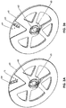
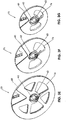
- each blade holder 60 has at least one blade 64 mounted on an outside face of the disk 61. If, as seen in Figure 3C , the shaving edge 65 of the blade 64 is at an angle 66 in which its distal end leads its travel, shaved ribbons S of polyolefin will be dispensed inside of the pipe P being shaved. If, as seen in Figure 3D , the shaving edge 65 of the blade 64 is at an angle 67 in which its distal end trails its travel, shaved ribbons S of polyolefin will be dispensed outside of the pipe P being shaved.
- a blade 64 is mounted in a V shaped recess 68 in the outer face of the disk 61.
- the recess 68 has two sets 69 and 71 of at least two holes, as shown two sets of three holes, which are registrable with at least two holes in the blade 64.
- the alignment of the blade holes with one set 69 of recess holes orients the blade 64 at the angle 66, causing shaved ribbons S of polyolefin to be dispensed inside of the pipe P.
- the alignment of the blade holes with the other set 71 of recess holes orients the blade 64 at the angle 67, causing shaved ribbons S of polyolefin to be dispensed outside of the pipe P.
- the blade 64 is secured in the recess 68 using screws 72.
- Multiple blades 64 can be mounted on a disk 61, preferably at equal angular displacements on the disk 61, with each blade 64 in a separate recess 68.
- the two blade holders 60 are mirror images to provide proper orientation of the blades and position in their V shaped recesses 68.
- Each blade holder 60 is mounted on its respective side of the facer F so that when rotating the blade edge 65 is leading and cutting and not trailing and dragging with the blade 64 on the trailing side of the V-shaped recess 68.
- the blade 64 is oriented to disperse the shaved ribbons S inside the pipe P, as seen in Figure 3C . They remain inside the pipe P during the entire facing operation. As a result, the ribbons S do not tangle in the facer F or the fusion machine and do not wrap tightly around the pipe P. Therefore, it is not necessary to periodically stop facing to clear the shaved ribbons S. Furthermore, ribbons S do not wrap around the pipe P, so the operator's view of the pipe periphery is not blocked. After facing, cleanup is easily accomplished by pulling a bundle of ribbons S from each pipe end.
- the blade 64 is positioned as seen in Figure 3D so ribbons S drop outside of the pipe P and down and do not tangle in the facer F. Also, for fusion of vertically oriented pipe P, the blade 64 on the lower blade holder 60 can be angled to disperse shaved ribbons S outside of its respective pipe P and the blade 64 on the upper blade holder can be angled to disperse shaved ribbons S inside of its respective pipe P.
- pairs of blade holders 60 of one diameter are interchangeable on the output shaft adapters 27 and 28 with pairs of blade holders 60 of another diameter.
- the lengths of the blades 64 can be sufficient to accommodate different diameter pipes P. Pipes P are typically of standardized sequential diameters.
- the same drive unit 10 can be used to face six different diameters of pipe P.
- the weight of a blade holder 60 can be reduced by voids 76 through the disk 61.
- the shaved ribbons S are to be dispensed inside of the pipe P as by the blade holder 60 of Figure 3C , it may necessary to close the voids 76 in some applications.
- the motor assembly 80 has a motor 81 with a gearbox 82 driving an output shaft 83 with a coupler 84 on its free end.
- a mounting frame 85 attached to the motor assembly 80 by a bracket 86 has a mounting plug 87 adapted for engagement with the socket 22 on the elongated frame 11 of the drive unit 10, as shown in Figure 2A .
- the coupler 84 on the motor assembly output shaft 83 and the input shaft coupler 31 of the drive unit 10 are spaced from the plug 87 and the socket 22 to align the couplers 84 and 31 on a common center axis 88.
- the couplers 84 and 31 are automatically mechanically engaged for rotation in unison when the motor assembly 80 is mounted on the drive unit 10 by telescoping the plug 87 into the socket 22.
- a detent pin 89 inserted into aligned apertures 91 secures the telescoped plug 87 and socket 22 with the couplers 84 and 31 engaged.
- the plug and socket components 87 and 22 could be switched to the drive unit 10 and motor assembly 80, respectively.
- the socket 22 and plug 87 are adapted for tool-free engagement preventing horizontal and vertical displacement of the motor assembly 80 in relation to the drive unit 10.
- the telescoping socket 22 and plug 87 are vertically aligned tubular members of square cross-section.
- the gearbox 82 is preferably a multi-speed gearbox operable at a speed selected to correspond to a cross-section of a pipe P being faced.
- a two-speed gearbox 82 can be set to low speed for larger and/or thicker pipe P and set to high speed for smaller and/or thinner pipe P.
- the horsepower required is governed in part by the speed of the blade 64, which is a function of RPM and pipe diameter, and wall thickness of the pipe P.
- the maximum required horsepower and blade holder RPM are governed by the largest and thickest pipe P. If the same RPM is used for smaller and thinner pipe, the blade speed will be slower and will not draw the full available horsepower.
- the drive unit gearbox 32 may be adapted to provide the two-speed operation of the drive unit output shaft 26 using a single speed motor assembly 80.
- a pair of handles 92 each spaced from the motor 81 and gearbox 82 on a corresponding wing 93 of the motor assembly 80, extend on axes 94 perpendicular to a diameter 95 of the motor 81 and gearbox 82 to facilitate lifting and manipulating the motor assembly 80 into position on the drive unit 10.
- the drive unit 10 is first mounted on the carriage guide rails R. This is accomplished by lifting the drive unit 10 above and squared with the carriage guide rails R, tilting the drive unit 10 so that the horizontal guide rail bracket 12 points toward one guide rail R, sliding it onto that guide rail R until that guide rail R is fully seated in the horizontal guide rail bracket 12, rocking the drive unit 10 on that guide rail R toward the other guide rail R until the vertical guide rail bracket 13 is fully seated on the other guide rail R and then swinging the vertical guide rail bracket latch 19 to its closed condition.
- the two blade holders 60 can each be lifted up and attached one at a time to the drive unit 10 by sliding them fully onto the hex nuts on the drive unit output shaft 26 and closing the latching assemblies 63 on the blade holders 60.
- the motor assembly 80 is mounted on the drive unit 10 by raising the motor assembly 80 above the drive unit 10, aligning the plug 87 of the motor assembly 80 with the socket 22 of the drive unit 10 and lowering the motor assembly 80 to fully engage the plug 87 in the socket 22, thereby simultaneously engaging the coupler 84 of the motor assembly output shaft 83 with the coupler 31 of the drive unit input shaft 25 and aligning the apertures 91 in the plug 87 and the socket 22.
- the detent pin 89 can then be inserted into the aligned apertures 91, completing the assembly of the facer F.
- Disassembly of the facer F involves essentially a reversal of the steps of assembly.
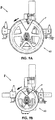
- the same facer F is seen in its assembled condition in Figure 9A with large diameter blade holders 60, as seen in Figure 3E , and in Figure 9B with small diameter blade holders 60, as seen in Figure 3G .
- the same drive unit 10 is used at its widest spacing of brackets in Figure 9A and at its narrowest spacing of brackets in Figure 9B .
- the same motor assembly 80 is used, but would be set at its lowest speed in Figure 9A and at its highest speed in Figure 9B .
- the facer F is seen in a horizontal orientation in Figures 9A and 9B and the blades 64 are angled for dispersing shaved ribbons S into the pipe P as seen in Figure 3C .
- the upper blade 64 would be angled for dispersing shaved ribbons S inside of the pipe P as seen in Figure 3C and the lower blade 64 would be angled for dispersing shaved ribbons S outside of the pipe P as seen in Figure 3D .
Landscapes
- Engineering & Computer Science (AREA)
- Mechanical Engineering (AREA)
- Life Sciences & Earth Sciences (AREA)
- Forests & Forestry (AREA)
- Machines For Manufacturing Corrugated Board In Mechanical Paper-Making Processes (AREA)
- Replacement Of Web Rolls (AREA)
- Mutual Connection Of Rods And Tubes (AREA)
Priority Applications (1)
| Application Number | Priority Date | Filing Date | Title |
|---|---|---|---|
| EP23193632.9A EP4257308B1 (de) | 2017-09-19 | 2018-09-11 | Facer zur fusion der enden von polyolefinrohren |
Applications Claiming Priority (3)
| Application Number | Priority Date | Filing Date | Title |
|---|---|---|---|
| US15/709,468 US10682780B2 (en) | 2017-09-19 | 2017-09-19 | Facer for end fusion of polyolefin pipes |
| PCT/US2018/050426 WO2019060176A1 (en) | 2017-09-19 | 2018-09-11 | TRAINING DEVICE FOR MELTING END OF POLYOLEFIN PIPES |
| EP18783602.8A EP3684598A1 (de) | 2017-09-19 | 2018-09-11 | Rohrablänger zur endfusion von polyolefinrohren |
Related Parent Applications (1)
| Application Number | Title | Priority Date | Filing Date |
|---|---|---|---|
| EP18783602.8A Division EP3684598A1 (de) | 2017-09-19 | 2018-09-11 | Rohrablänger zur endfusion von polyolefinrohren |
Related Child Applications (1)
| Application Number | Title | Priority Date | Filing Date |
|---|---|---|---|
| EP23193632.9A Division EP4257308B1 (de) | 2017-09-19 | 2018-09-11 | Facer zur fusion der enden von polyolefinrohren |
Publications (3)
| Publication Number | Publication Date |
|---|---|
| EP3925762A2 true EP3925762A2 (de) | 2021-12-22 |
| EP3925762A3 EP3925762A3 (de) | 2022-03-02 |
| EP3925762B1 EP3925762B1 (de) | 2023-08-30 |
Family
ID=63799072
Family Applications (3)
| Application Number | Title | Priority Date | Filing Date |
|---|---|---|---|
| EP21190708.4A Active EP3925762B1 (de) | 2017-09-19 | 2018-09-11 | Facer zur fusion der enden von polyolefinrohren |
| EP18783602.8A Withdrawn EP3684598A1 (de) | 2017-09-19 | 2018-09-11 | Rohrablänger zur endfusion von polyolefinrohren |
| EP23193632.9A Active EP4257308B1 (de) | 2017-09-19 | 2018-09-11 | Facer zur fusion der enden von polyolefinrohren |
Family Applications After (2)
| Application Number | Title | Priority Date | Filing Date |
|---|---|---|---|
| EP18783602.8A Withdrawn EP3684598A1 (de) | 2017-09-19 | 2018-09-11 | Rohrablänger zur endfusion von polyolefinrohren |
| EP23193632.9A Active EP4257308B1 (de) | 2017-09-19 | 2018-09-11 | Facer zur fusion der enden von polyolefinrohren |
Country Status (4)
| Country | Link |
|---|---|
| US (2) | US10682780B2 (de) |
| EP (3) | EP3925762B1 (de) |
| AU (3) | AU2018337624B2 (de) |
| WO (1) | WO2019060176A1 (de) |
Citations (1)
| Publication number | Priority date | Publication date | Assignee | Title |
|---|---|---|---|---|
| US5725724A (en) | 1996-01-08 | 1998-03-10 | Tdw Delaware, Inc. | Plastic pipe facer for butt fusion application |
Family Cites Families (8)
| Publication number | Priority date | Publication date | Assignee | Title |
|---|---|---|---|---|
| US3013925A (en) * | 1959-04-03 | 1961-12-19 | Phillips Petroleum Co | Method and means for welding thermoplastic pipes |
| FI40341B (de) * | 1962-09-15 | 1968-09-02 | Foerenade Plastfabriker Ab W & | |
| US3552265A (en) * | 1968-11-01 | 1971-01-05 | Phillips Petroleum Co | Method and apparatus for facing thermoplastic pipe |
| US3729360A (en) * | 1971-03-08 | 1973-04-24 | A Mcelroy | Portable thermoplastic pipe fusion apparatus |
| US3793119A (en) * | 1972-01-04 | 1974-02-19 | W Province | Facing tool for plastic pipe fusion apparatus |
| AU4254296A (en) * | 1994-11-21 | 1996-06-17 | Ulrike Richter | Butt-welding device for pipes made of thermoplastic materials |
| US5814182A (en) * | 1997-09-19 | 1998-09-29 | Mcelroy Manufacturing, Inc. | Self-contained and self-propelled machine for heat fusing polyolefin pipes |
| US9604288B2 (en) * | 2013-09-17 | 2017-03-28 | Mcelroy Manufacturing, Inc. | Cartesian pipe facer |
-
2017
- 2017-09-19 US US15/709,468 patent/US10682780B2/en active Active
-
2018
- 2018-09-11 EP EP21190708.4A patent/EP3925762B1/de active Active
- 2018-09-11 EP EP18783602.8A patent/EP3684598A1/de not_active Withdrawn
- 2018-09-11 WO PCT/US2018/050426 patent/WO2019060176A1/en not_active Ceased
- 2018-09-11 EP EP23193632.9A patent/EP4257308B1/de active Active
- 2018-09-11 AU AU2018337624A patent/AU2018337624B2/en active Active
-
2020
- 2020-06-08 US US16/895,726 patent/US11034039B2/en active Active
-
2024
- 2024-02-06 AU AU2024200713A patent/AU2024200713B2/en active Active
-
2026
- 2026-01-09 AU AU2026200134A patent/AU2026200134A1/en active Pending
Patent Citations (1)
| Publication number | Priority date | Publication date | Assignee | Title |
|---|---|---|---|---|
| US5725724A (en) | 1996-01-08 | 1998-03-10 | Tdw Delaware, Inc. | Plastic pipe facer for butt fusion application |
Also Published As
| Publication number | Publication date |
|---|---|
| US20200338773A1 (en) | 2020-10-29 |
| EP3925762A3 (de) | 2022-03-02 |
| EP4257308B1 (de) | 2025-12-31 |
| EP3684598A1 (de) | 2020-07-29 |
| EP3925762B1 (de) | 2023-08-30 |
| EP4257308A2 (de) | 2023-10-11 |
| AU2018337624B2 (en) | 2023-11-23 |
| AU2018337624A1 (en) | 2020-03-12 |
| US20190084170A1 (en) | 2019-03-21 |
| WO2019060176A1 (en) | 2019-03-28 |
| AU2024200713A1 (en) | 2024-02-22 |
| AU2024200713B2 (en) | 2025-10-09 |
| AU2026200134A1 (en) | 2026-01-29 |
| US11034039B2 (en) | 2021-06-15 |
| US10682780B2 (en) | 2020-06-16 |
| EP4257308A3 (de) | 2024-01-10 |
Similar Documents
| Publication | Publication Date | Title |
|---|---|---|
| US8065936B2 (en) | Offset pass through device | |
| CN109510118B (zh) | 一种电缆绝缘层自动剥除装置 | |
| SE509427C2 (sv) | Manöveranordning | |
| CN111155461A (zh) | 一种道闸机芯及道闸 | |
| US11034039B2 (en) | Facer for end fusion of polyolefin pipes | |
| JP3917851B2 (ja) | 弁箱付き弁座の溶接結合部切削装置 | |
| CN109236987B (zh) | 齿轮组件及具有其的电缆绝缘层剥除装置 | |
| US7442030B2 (en) | Molded component retrieving apparatus and a molding machine having the molded component retrieving apparatus mounted thereon | |
| EP0613533A1 (de) | Wartungsfreundlicher drehzahlvariator und methoden | |
| CN114833855B (zh) | 一种可变角度的管件夹持装置及管件夹持方法 | |
| US4412443A (en) | Roller forming machine with lengthwise adjustable heads | |
| CN111605216B (zh) | 一种碳纤维汽车零件加工系统与加工方法 | |
| CN212316758U (zh) | 一种道闸机芯及道闸 | |
| CN212458324U (zh) | 一种雨刮器角度检测装置 | |
| CN213319872U (zh) | 一种用于电机拆卸的魔术圆盘 | |
| CN212311369U (zh) | 螺丝用锁紧装置及系统 | |
| CN219035037U (zh) | 一种便于安装的离心压缩机高速传动齿轮轴 | |
| CN220921498U (zh) | 一种电机联轴器工装 | |
| CN223876955U (zh) | 变桨电机对接工装 | |
| CN220427715U (zh) | 一种立车的防护罩装置 | |
| CN216951554U (zh) | 一种可靠固定的内啮合齿轮 | |
| CN112192136B (zh) | 装夹工装 | |
| US20260035982A1 (en) | Interchangeable rail to jackshaft conversion | |
| CN211516258U (zh) | 一种切割锯片快速装配结构 | |
| CN108500973A (zh) | 抓取结构及分拣机器人 |
Legal Events
| Date | Code | Title | Description |
|---|---|---|---|
| PUAI | Public reference made under article 153(3) epc to a published international application that has entered the european phase |
Free format text: ORIGINAL CODE: 0009012 |
|
| STAA | Information on the status of an ep patent application or granted ep patent |
Free format text: STATUS: REQUEST FOR EXAMINATION WAS MADE |
|
| 17P | Request for examination filed |
Effective date: 20210811 |
|
| AC | Divisional application: reference to earlier application |
Ref document number: 3684598 Country of ref document: EP Kind code of ref document: P |
|
| AK | Designated contracting states |
Kind code of ref document: A2 Designated state(s): AL AT BE BG CH CY CZ DE DK EE ES FI FR GB GR HR HU IE IS IT LI LT LU LV MC MK MT NL NO PL PT RO RS SE SI SK SM TR |
|
| PUAL | Search report despatched |
Free format text: ORIGINAL CODE: 0009013 |
|
| AK | Designated contracting states |
Kind code of ref document: A3 Designated state(s): AL AT BE BG CH CY CZ DE DK EE ES FI FR GB GR HR HU IE IS IT LI LT LU LV MC MK MT NL NO PL PT RO RS SE SI SK SM TR |
|
| RIC1 | Information provided on ipc code assigned before grant |
Ipc: B29C 65/20 20060101ALN20220124BHEP Ipc: B26D 7/06 20060101ALI20220124BHEP Ipc: B26D 7/01 20060101ALI20220124BHEP Ipc: B26D 7/00 20060101ALI20220124BHEP Ipc: B26D 3/16 20060101ALI20220124BHEP Ipc: B26D 1/28 20060101ALI20220124BHEP Ipc: B23B 5/16 20060101ALI20220124BHEP Ipc: B23B 5/08 20060101ALI20220124BHEP Ipc: B29C 65/02 20060101AFI20220124BHEP |
|
| GRAP | Despatch of communication of intention to grant a patent |
Free format text: ORIGINAL CODE: EPIDOSNIGR1 |
|
| STAA | Information on the status of an ep patent application or granted ep patent |
Free format text: STATUS: GRANT OF PATENT IS INTENDED |
|
| RIC1 | Information provided on ipc code assigned before grant |
Ipc: B29K 23/00 20060101ALN20230228BHEP Ipc: B29C 65/20 20060101ALN20230228BHEP Ipc: B26D 7/06 20060101ALI20230228BHEP Ipc: B26D 7/01 20060101ALI20230228BHEP Ipc: B26D 7/00 20060101ALI20230228BHEP Ipc: B26D 3/16 20060101ALI20230228BHEP Ipc: B26D 1/28 20060101ALI20230228BHEP Ipc: B23B 5/16 20060101ALI20230228BHEP Ipc: B23B 5/08 20060101ALI20230228BHEP Ipc: B29C 65/02 20060101AFI20230228BHEP |
|
| INTG | Intention to grant announced |
Effective date: 20230324 |
|
| P01 | Opt-out of the competence of the unified patent court (upc) registered |
Effective date: 20230530 |
|
| GRAS | Grant fee paid |
Free format text: ORIGINAL CODE: EPIDOSNIGR3 |
|
| GRAA | (expected) grant |
Free format text: ORIGINAL CODE: 0009210 |
|
| STAA | Information on the status of an ep patent application or granted ep patent |
Free format text: STATUS: THE PATENT HAS BEEN GRANTED |
|
| AC | Divisional application: reference to earlier application |
Ref document number: 3684598 Country of ref document: EP Kind code of ref document: P |
|
| AK | Designated contracting states |
Kind code of ref document: B1 Designated state(s): AL AT BE BG CH CY CZ DE DK EE ES FI FR GB GR HR HU IE IS IT LI LT LU LV MC MK MT NL NO PL PT RO RS SE SI SK SM TR |
|
| REG | Reference to a national code |
Ref country code: GB Ref legal event code: FG4D |
|
| REG | Reference to a national code |
Ref country code: CH Ref legal event code: EP |
|
| REG | Reference to a national code |
Ref country code: DE Ref legal event code: R096 Ref document number: 602018056807 Country of ref document: DE |
|
| REG | Reference to a national code |
Ref country code: IE Ref legal event code: FG4D |
|
| REG | Reference to a national code |
Ref country code: LT Ref legal event code: MG9D |
|
| REG | Reference to a national code |
Ref country code: NL Ref legal event code: MP Effective date: 20230830 |
|
| REG | Reference to a national code |
Ref country code: AT Ref legal event code: MK05 Ref document number: 1604903 Country of ref document: AT Kind code of ref document: T Effective date: 20230830 |
|
| PG25 | Lapsed in a contracting state [announced via postgrant information from national office to epo] |
Ref country code: GR Free format text: LAPSE BECAUSE OF FAILURE TO SUBMIT A TRANSLATION OF THE DESCRIPTION OR TO PAY THE FEE WITHIN THE PRESCRIBED TIME-LIMIT Effective date: 20231201 |
|
| PG25 | Lapsed in a contracting state [announced via postgrant information from national office to epo] |
Ref country code: IS Free format text: LAPSE BECAUSE OF FAILURE TO SUBMIT A TRANSLATION OF THE DESCRIPTION OR TO PAY THE FEE WITHIN THE PRESCRIBED TIME-LIMIT Effective date: 20231230 |
|
| PG25 | Lapsed in a contracting state [announced via postgrant information from national office to epo] |
Ref country code: SE Free format text: LAPSE BECAUSE OF FAILURE TO SUBMIT A TRANSLATION OF THE DESCRIPTION OR TO PAY THE FEE WITHIN THE PRESCRIBED TIME-LIMIT Effective date: 20230830 Ref country code: RS Free format text: LAPSE BECAUSE OF FAILURE TO SUBMIT A TRANSLATION OF THE DESCRIPTION OR TO PAY THE FEE WITHIN THE PRESCRIBED TIME-LIMIT Effective date: 20230830 Ref country code: NO Free format text: LAPSE BECAUSE OF FAILURE TO SUBMIT A TRANSLATION OF THE DESCRIPTION OR TO PAY THE FEE WITHIN THE PRESCRIBED TIME-LIMIT Effective date: 20231130 Ref country code: LV Free format text: LAPSE BECAUSE OF FAILURE TO SUBMIT A TRANSLATION OF THE DESCRIPTION OR TO PAY THE FEE WITHIN THE PRESCRIBED TIME-LIMIT Effective date: 20230830 Ref country code: LT Free format text: LAPSE BECAUSE OF FAILURE TO SUBMIT A TRANSLATION OF THE DESCRIPTION OR TO PAY THE FEE WITHIN THE PRESCRIBED TIME-LIMIT Effective date: 20230830 Ref country code: IS Free format text: LAPSE BECAUSE OF FAILURE TO SUBMIT A TRANSLATION OF THE DESCRIPTION OR TO PAY THE FEE WITHIN THE PRESCRIBED TIME-LIMIT Effective date: 20231230 Ref country code: HR Free format text: LAPSE BECAUSE OF FAILURE TO SUBMIT A TRANSLATION OF THE DESCRIPTION OR TO PAY THE FEE WITHIN THE PRESCRIBED TIME-LIMIT Effective date: 20230830 Ref country code: GR Free format text: LAPSE BECAUSE OF FAILURE TO SUBMIT A TRANSLATION OF THE DESCRIPTION OR TO PAY THE FEE WITHIN THE PRESCRIBED TIME-LIMIT Effective date: 20231201 Ref country code: FI Free format text: LAPSE BECAUSE OF FAILURE TO SUBMIT A TRANSLATION OF THE DESCRIPTION OR TO PAY THE FEE WITHIN THE PRESCRIBED TIME-LIMIT Effective date: 20230830 Ref country code: AT Free format text: LAPSE BECAUSE OF FAILURE TO SUBMIT A TRANSLATION OF THE DESCRIPTION OR TO PAY THE FEE WITHIN THE PRESCRIBED TIME-LIMIT Effective date: 20230830 |
|
| PG25 | Lapsed in a contracting state [announced via postgrant information from national office to epo] |
Ref country code: PL Free format text: LAPSE BECAUSE OF FAILURE TO SUBMIT A TRANSLATION OF THE DESCRIPTION OR TO PAY THE FEE WITHIN THE PRESCRIBED TIME-LIMIT Effective date: 20230830 Ref country code: NL Free format text: LAPSE BECAUSE OF FAILURE TO SUBMIT A TRANSLATION OF THE DESCRIPTION OR TO PAY THE FEE WITHIN THE PRESCRIBED TIME-LIMIT Effective date: 20230830 |
|
| PG25 | Lapsed in a contracting state [announced via postgrant information from national office to epo] |
Ref country code: ES Free format text: LAPSE BECAUSE OF FAILURE TO SUBMIT A TRANSLATION OF THE DESCRIPTION OR TO PAY THE FEE WITHIN THE PRESCRIBED TIME-LIMIT Effective date: 20230830 |
|
| PG25 | Lapsed in a contracting state [announced via postgrant information from national office to epo] |
Ref country code: SM Free format text: LAPSE BECAUSE OF FAILURE TO SUBMIT A TRANSLATION OF THE DESCRIPTION OR TO PAY THE FEE WITHIN THE PRESCRIBED TIME-LIMIT Effective date: 20230830 Ref country code: RO Free format text: LAPSE BECAUSE OF FAILURE TO SUBMIT A TRANSLATION OF THE DESCRIPTION OR TO PAY THE FEE WITHIN THE PRESCRIBED TIME-LIMIT Effective date: 20230830 Ref country code: ES Free format text: LAPSE BECAUSE OF FAILURE TO SUBMIT A TRANSLATION OF THE DESCRIPTION OR TO PAY THE FEE WITHIN THE PRESCRIBED TIME-LIMIT Effective date: 20230830 Ref country code: EE Free format text: LAPSE BECAUSE OF FAILURE TO SUBMIT A TRANSLATION OF THE DESCRIPTION OR TO PAY THE FEE WITHIN THE PRESCRIBED TIME-LIMIT Effective date: 20230830 Ref country code: DK Free format text: LAPSE BECAUSE OF FAILURE TO SUBMIT A TRANSLATION OF THE DESCRIPTION OR TO PAY THE FEE WITHIN THE PRESCRIBED TIME-LIMIT Effective date: 20230830 Ref country code: CZ Free format text: LAPSE BECAUSE OF FAILURE TO SUBMIT A TRANSLATION OF THE DESCRIPTION OR TO PAY THE FEE WITHIN THE PRESCRIBED TIME-LIMIT Effective date: 20230830 Ref country code: PT Free format text: LAPSE BECAUSE OF FAILURE TO SUBMIT A TRANSLATION OF THE DESCRIPTION OR TO PAY THE FEE WITHIN THE PRESCRIBED TIME-LIMIT Effective date: 20240102 Ref country code: SK Free format text: LAPSE BECAUSE OF FAILURE TO SUBMIT A TRANSLATION OF THE DESCRIPTION OR TO PAY THE FEE WITHIN THE PRESCRIBED TIME-LIMIT Effective date: 20230830 |
|
| REG | Reference to a national code |
Ref country code: CH Ref legal event code: PL |
|
| PG25 | Lapsed in a contracting state [announced via postgrant information from national office to epo] |
Ref country code: LU Free format text: LAPSE BECAUSE OF NON-PAYMENT OF DUE FEES Effective date: 20230911 |
|
| REG | Reference to a national code |
Ref country code: BE Ref legal event code: MM Effective date: 20230930 |
|
| PG25 | Lapsed in a contracting state [announced via postgrant information from national office to epo] |
Ref country code: LU Free format text: LAPSE BECAUSE OF NON-PAYMENT OF DUE FEES Effective date: 20230911 Ref country code: MC Free format text: LAPSE BECAUSE OF FAILURE TO SUBMIT A TRANSLATION OF THE DESCRIPTION OR TO PAY THE FEE WITHIN THE PRESCRIBED TIME-LIMIT Effective date: 20230830 |
|
| REG | Reference to a national code |
Ref country code: DE Ref legal event code: R097 Ref document number: 602018056807 Country of ref document: DE |
|
| REG | Reference to a national code |
Ref country code: IE Ref legal event code: MM4A |
|
| PG25 | Lapsed in a contracting state [announced via postgrant information from national office to epo] |
Ref country code: IE Free format text: LAPSE BECAUSE OF NON-PAYMENT OF DUE FEES Effective date: 20230911 |
|
| PLBE | No opposition filed within time limit |
Free format text: ORIGINAL CODE: 0009261 |
|
| STAA | Information on the status of an ep patent application or granted ep patent |
Free format text: STATUS: NO OPPOSITION FILED WITHIN TIME LIMIT |
|
| PG25 | Lapsed in a contracting state [announced via postgrant information from national office to epo] |
Ref country code: CH Free format text: LAPSE BECAUSE OF NON-PAYMENT OF DUE FEES Effective date: 20230930 |
|
| PG25 | Lapsed in a contracting state [announced via postgrant information from national office to epo] |
Ref country code: IE Free format text: LAPSE BECAUSE OF NON-PAYMENT OF DUE FEES Effective date: 20230911 Ref country code: FR Free format text: LAPSE BECAUSE OF NON-PAYMENT OF DUE FEES Effective date: 20231030 Ref country code: CH Free format text: LAPSE BECAUSE OF NON-PAYMENT OF DUE FEES Effective date: 20230930 Ref country code: SI Free format text: LAPSE BECAUSE OF FAILURE TO SUBMIT A TRANSLATION OF THE DESCRIPTION OR TO PAY THE FEE WITHIN THE PRESCRIBED TIME-LIMIT Effective date: 20230830 |
|
| 26N | No opposition filed |
Effective date: 20240603 |
|
| PG25 | Lapsed in a contracting state [announced via postgrant information from national office to epo] |
Ref country code: BE Free format text: LAPSE BECAUSE OF NON-PAYMENT OF DUE FEES Effective date: 20230930 |
|
| PG25 | Lapsed in a contracting state [announced via postgrant information from national office to epo] |
Ref country code: BG Free format text: LAPSE BECAUSE OF FAILURE TO SUBMIT A TRANSLATION OF THE DESCRIPTION OR TO PAY THE FEE WITHIN THE PRESCRIBED TIME-LIMIT Effective date: 20230830 |
|
| PG25 | Lapsed in a contracting state [announced via postgrant information from national office to epo] |
Ref country code: BG Free format text: LAPSE BECAUSE OF FAILURE TO SUBMIT A TRANSLATION OF THE DESCRIPTION OR TO PAY THE FEE WITHIN THE PRESCRIBED TIME-LIMIT Effective date: 20230830 |
|
| PG25 | Lapsed in a contracting state [announced via postgrant information from national office to epo] |
Ref country code: CY Free format text: LAPSE BECAUSE OF FAILURE TO SUBMIT A TRANSLATION OF THE DESCRIPTION OR TO PAY THE FEE WITHIN THE PRESCRIBED TIME-LIMIT; INVALID AB INITIO Effective date: 20180911 |
|
| PG25 | Lapsed in a contracting state [announced via postgrant information from national office to epo] |
Ref country code: HU Free format text: LAPSE BECAUSE OF FAILURE TO SUBMIT A TRANSLATION OF THE DESCRIPTION OR TO PAY THE FEE WITHIN THE PRESCRIBED TIME-LIMIT; INVALID AB INITIO Effective date: 20180911 |
|
| PGFP | Annual fee paid to national office [announced via postgrant information from national office to epo] |
Ref country code: DE Payment date: 20250919 Year of fee payment: 8 |
|
| PGFP | Annual fee paid to national office [announced via postgrant information from national office to epo] |
Ref country code: IT Payment date: 20250923 Year of fee payment: 8 |
|
| PGFP | Annual fee paid to national office [announced via postgrant information from national office to epo] |
Ref country code: GB Payment date: 20250729 Year of fee payment: 8 |
|
| PG25 | Lapsed in a contracting state [announced via postgrant information from national office to epo] |
Ref country code: TR Free format text: LAPSE BECAUSE OF FAILURE TO SUBMIT A TRANSLATION OF THE DESCRIPTION OR TO PAY THE FEE WITHIN THE PRESCRIBED TIME-LIMIT Effective date: 20230830 |