EP3925429A1 - Feldhäcksler - Google Patents
Feldhäcksler Download PDFInfo
- Publication number
- EP3925429A1 EP3925429A1 EP21170342.6A EP21170342A EP3925429A1 EP 3925429 A1 EP3925429 A1 EP 3925429A1 EP 21170342 A EP21170342 A EP 21170342A EP 3925429 A1 EP3925429 A1 EP 3925429A1
- Authority
- EP
- European Patent Office
- Prior art keywords
- forage harvester
- chopping drum
- drum assembly
- shaft
- parts
- Prior art date
- Legal status (The legal status is an assumption and is not a legal conclusion. Google has not performed a legal analysis and makes no representation as to the accuracy of the status listed.)
- Granted
Links
Images


Classifications
-
- A—HUMAN NECESSITIES
- A01—AGRICULTURE; FORESTRY; ANIMAL HUSBANDRY; HUNTING; TRAPPING; FISHING
- A01D—HARVESTING; MOWING
- A01D43/00—Mowers combined with apparatus performing additional operations while mowing
- A01D43/10—Mowers combined with apparatus performing additional operations while mowing with means for crushing or bruising the mown crop
- A01D43/107—Mounting means
-
- A—HUMAN NECESSITIES
- A01—AGRICULTURE; FORESTRY; ANIMAL HUSBANDRY; HUNTING; TRAPPING; FISHING
- A01D—HARVESTING; MOWING
- A01D41/00—Combines, i.e. harvesters or mowers combined with threshing devices
- A01D41/12—Details of combines
- A01D41/14—Mowing tables
- A01D41/145—Header lifting devices
-
- A—HUMAN NECESSITIES
- A01—AGRICULTURE; FORESTRY; ANIMAL HUSBANDRY; HUNTING; TRAPPING; FISHING
- A01D—HARVESTING; MOWING
- A01D41/00—Combines, i.e. harvesters or mowers combined with threshing devices
- A01D41/06—Combines with headers
-
- A—HUMAN NECESSITIES
- A01—AGRICULTURE; FORESTRY; ANIMAL HUSBANDRY; HUNTING; TRAPPING; FISHING
- A01D—HARVESTING; MOWING
- A01D43/00—Mowers combined with apparatus performing additional operations while mowing
- A01D43/08—Mowers combined with apparatus performing additional operations while mowing with means for cutting up the mown crop, e.g. forage harvesters
- A01D43/086—Mowers combined with apparatus performing additional operations while mowing with means for cutting up the mown crop, e.g. forage harvesters and means for collecting, gathering or loading mown material
-
- F—MECHANICAL ENGINEERING; LIGHTING; HEATING; WEAPONS; BLASTING
- F16—ENGINEERING ELEMENTS AND UNITS; GENERAL MEASURES FOR PRODUCING AND MAINTAINING EFFECTIVE FUNCTIONING OF MACHINES OR INSTALLATIONS; THERMAL INSULATION IN GENERAL
- F16C—SHAFTS; FLEXIBLE SHAFTS; ELEMENTS OR CRANKSHAFT MECHANISMS; ROTARY BODIES OTHER THAN GEARING ELEMENTS; BEARINGS
- F16C21/00—Combinations of sliding-contact bearings with ball or roller bearings, for exclusively rotary movement
-
- F—MECHANICAL ENGINEERING; LIGHTING; HEATING; WEAPONS; BLASTING
- F16—ENGINEERING ELEMENTS AND UNITS; GENERAL MEASURES FOR PRODUCING AND MAINTAINING EFFECTIVE FUNCTIONING OF MACHINES OR INSTALLATIONS; THERMAL INSULATION IN GENERAL
- F16C—SHAFTS; FLEXIBLE SHAFTS; ELEMENTS OR CRANKSHAFT MECHANISMS; ROTARY BODIES OTHER THAN GEARING ELEMENTS; BEARINGS
- F16C23/00—Bearings for exclusively rotary movement adjustable for aligning or positioning
- F16C23/06—Ball or roller bearings
- F16C23/08—Ball or roller bearings self-adjusting
- F16C23/082—Ball or roller bearings self-adjusting by means of at least one substantially spherical surface
- F16C23/084—Ball or roller bearings self-adjusting by means of at least one substantially spherical surface sliding on a complementary spherical surface
-
- A—HUMAN NECESSITIES
- A01—AGRICULTURE; FORESTRY; ANIMAL HUSBANDRY; HUNTING; TRAPPING; FISHING
- A01D—HARVESTING; MOWING
- A01D43/00—Mowers combined with apparatus performing additional operations while mowing
- A01D43/08—Mowers combined with apparatus performing additional operations while mowing with means for cutting up the mown crop, e.g. forage harvesters
-
- F—MECHANICAL ENGINEERING; LIGHTING; HEATING; WEAPONS; BLASTING
- F16—ENGINEERING ELEMENTS AND UNITS; GENERAL MEASURES FOR PRODUCING AND MAINTAINING EFFECTIVE FUNCTIONING OF MACHINES OR INSTALLATIONS; THERMAL INSULATION IN GENERAL
- F16C—SHAFTS; FLEXIBLE SHAFTS; ELEMENTS OR CRANKSHAFT MECHANISMS; ROTARY BODIES OTHER THAN GEARING ELEMENTS; BEARINGS
- F16C2310/00—Agricultural machines
-
- F—MECHANICAL ENGINEERING; LIGHTING; HEATING; WEAPONS; BLASTING
- F16—ENGINEERING ELEMENTS AND UNITS; GENERAL MEASURES FOR PRODUCING AND MAINTAINING EFFECTIVE FUNCTIONING OF MACHINES OR INSTALLATIONS; THERMAL INSULATION IN GENERAL
- F16C—SHAFTS; FLEXIBLE SHAFTS; ELEMENTS OR CRANKSHAFT MECHANISMS; ROTARY BODIES OTHER THAN GEARING ELEMENTS; BEARINGS
- F16C35/00—Rigid support of bearing units; Housings, e.g. caps, covers
- F16C35/04—Rigid support of bearing units; Housings, e.g. caps, covers in the case of ball or roller bearings
- F16C35/06—Mounting or dismounting of ball or roller bearings; Fixing them onto shaft or in housing
Definitions
- the present invention relates to a forage harvester.
- a forage harvester typically has a chassis with frame parts extending in the longitudinal direction of the forage harvester and connected to one another by carriers running in the transverse direction, on which a front axle, rear wheels, an engine, a chopping mechanism, etc. are mounted.
- the main component of the chopping unit is a chopping drum fitted with knives.
- a chopping drum fitted with knives.
- the crop is cut into pieces.
- the chopping drum In order to rotate evenly through the crop despite changing resistance, the chopping drum must have a large moment of inertia and a correspondingly large diameter and high mass; This and the cutting forces on the knives, which fluctuate greatly during operation, make a powerful shaft and correspondingly large, heavy-duty bearings necessary. If the bearing clearance allows vibratory movements of the cutterhead, this impairs the quality of the cut and also leads to it This leads to increased wear on the bearings, which in turn increases the bearing play.
- One object of the invention is to create a forage harvester which enables low-wear storage and precise guidance of the movement of the chopping drum over a long period of time.
- each clamp bearing does not define the axis of rotation for itself, but each clamp bearing defines only a single point, the center of the spherical surface, as a point through which the axis of rotation must run. In this way, the chopping drum assembly can be mounted on the frame parts free of internal tension and rotate relative to these with little friction and low wear.
- both elements of the clamping bearing should have spherical surfaces which, because they are shaped complementary to one another, touch one another over a large area.
- the assembly-side element of the clamping bearing uts is typically a ring through which a shaft of the chopping drum assembly extends and in which the spherical surface is an outer peripheral surface.
- the element on the frame part should comprise two parts over which the spherical surface of the element on the frame part is distributed.
- a lower of the two parts should be an integral part of one of the frame parts in order to be able to stably support the chopping drum assembly even when the upper of the two parts is detached.
- a clamping screw can be sufficient.
- an articulated connection can be provided between the parts on the opposite side.
- the chopping drum assembly comprises a shaft rotatably received in the clamping bearings and an adapter for a harvesting header connected to the shaft in a rotationally fixed manner. By rotating the shaft and with it the adapter, the height above the bottom of the header can be adjusted.
- the chopping drum is for its part preferably rotatably mounted on the shaft. Since the shaft must therefore only perform small, slow rotations, it can be slide-mounted in the clamping bearing.
- a hydraulic actuator can be provided between the frame parts and the chopping drum assembly.
- Fig. 1 shows a schematic representation of a forage harvester 1.
- the body of the forage harvester 1 is shown cut open in its front part below a driver's cab 2 in order to be able to show internal, crop-processing assemblies of the forage harvester.
- One of these assemblies is a chopping drum assembly with a chopping drum 4 rotating about an axis 3 extending in the transverse direction of the vehicle.
- a conveying device 5 for harvested crop is upstream of the chopper drum assembly.
- the conveying device 5 comprises several pairs of rollers 6, 7, which each delimit a gap and are driven to rotate in opposite directions in order to feed the harvested crop passing through the gap to the chopping drum 4.
- the conveying device 5 in turn carries a harvesting header 6 which can be exchanged in adaptation to the plant material to be recovered.
- shredded crop is fed to a post-accelerator 9, which gives the shredded crop the necessary speed to pass through an ejection chute 10 and be transferred to an escort vehicle (not shown).
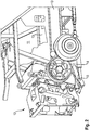
- Fig. 2 and 3 shows a front part of a frame 11 of the forage harvester 1 and the chopping drum assembly 12 mounted therein in a perspective view obliquely from the front.
- the frame 11 comprises two frame parts 13 extending essentially horizontally in the longitudinal direction of the vehicle, for example in the form of T or double T profiles which are rigidly connected to one another by cross members (not visible in the figure) and on which a front axle and steerable rear wheels of the forage harvester 1 are suspended.
- the front end of the frame parts 13 is in Fig. 2 hidden behind a pulley 14 driving the rotation of the chopping drum or a housing 15 surrounding the chopping drum.
- Fig. 3 shows this front end in a detailed view.
- the frame part 13 ends in a clamping bearing 16 which is provided to receive a shaft of the chopping drum assembly 12. Only one ring-shaped element 17 of the chopping drum assembly 12 is shown, which is provided to receive a shaft which - as will be described in more detail below - connects the belt pulley 14 to the housing 15 and the chopping drum 4.
- An element 18 of the clamping bearing 16 on the frame part side comprises a part 19 that is firmly connected to the frame part 13 in the form of an annular sector, the concavity 20 of which (see also FIG Fig. 4 ) facing upwards, so that the chopping drum assembly 12 can be stored in a stable manner during installation in or removal from the forage harvester 1 by inserting the annular element 17 into the concavity 20.
- a second ring sector-shaped part 21 of the frame part-side element 18 is connected to the frame part 13 via a joint 22.
- the front tips of the parts 19, 21 each have a hole, in which a clamping screw 23 can be mounted.
- the clamping screw 23 is removed and the part 21 is folded up.
- the concavity 20 is part of a spherical surface, as is the outer circumferential surface 24 of the annular element 17.
- the annular element 17, when inserted into the concavity 20, is therefore pivotable about two axes orthogonal to the shaft.
- the alignment of its axis can be freely adapted to any tolerances in the positioning and alignment of the parts 19, so that when the clamping screw 23 is tightened and the annular element 17 between the parts 19, 21 is clamped, this does not result in any internal stresses in the chopping drum assembly 12.
- the spherical surfaces of the concavity 20 and the outer peripheral surface 24 each have the same radii;
- the part 21 can have a concavity with the same radius, so that the parts 19, 21 in the tightened state bear against the outer circumferential surface 24 over a large area.
- Fig. 5 shows an axial section of one of the clamping bearings 16 and the shaft 25 of the chopping drum assembly 12 received therein.
- the center of the spherical surfaces of the concavity 20 and the outer peripheral surface 24 lie on the axis 3 of the shaft 25.
- the shaft 25 comprises a hollow shaft 26 and a concentric one inner shaft 27 running in its interior.
- the inner shaft 27 carries the pulley 14 on one side of the clamping bearing 16 and the chopping drum 4 on the other.
- the hollow shaft 26 carries the housing 15.
- a roller bearing 28 between the two ensures the rotatability of hollow shaft 26 and Inner shaft 27 secure relative to one another, so that the pulley 14 can drive the rotation of the chopping drum 4 while the housing 15 remains at rest.
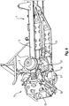
- Fig. 6 shows a view of the frame of the forage harvester 1 and the housing 15 of the chopping drum assembly 12 obliquely from below.
- a square adapter 30 is provided on the front of the housing 15 in order to mount the header 8 (not shown in this figure) or to couple a lifting machine to it to support the installation and removal of the chopping drum assembly 12 from the forage harvester 1.
- a hydraulic actuator 31 extends in the longitudinal direction of the vehicle under each of the frame parts 13. A rear end of each actuator 31 is connected to the frame, the front ends jointly engage a crossbar 32 of the housing. When the actuators 31 extend together, they pivot the housing 15 about the axis 3 and thereby possibly lift the header 8 mounted on the adapter 30.
Landscapes
- Engineering & Computer Science (AREA)
- General Engineering & Computer Science (AREA)
- Life Sciences & Earth Sciences (AREA)
- Environmental Sciences (AREA)
- Mechanical Engineering (AREA)
- Harvester Elements (AREA)
- Threshing Machine Elements (AREA)
- Soil Sciences (AREA)
Abstract
Description
- Die vorliegende Erfindung betrifft einen Feldhäcksler.
- Ein Feldhäcksler hat typischerweise ein Fahrgestell mit sich in Längsrichtung des Feldhäckslers erstreckenden und durch in Querrichtung verlaufende Träger miteinander verbundenen Rahmenteilen, an dem eine Vorderachse, Hinterräder, ein Motor, ein Häckselwerk etc. montiert sind.
- Hauptbestandteil des Häckselwerks ist eine mit Messern besetzte Häckseltrommel. Indem ein Strom von Erntegut auf die Häckseltrommel zu gefördert wird, während die Häckseltrommel rotiert, wird das Erntegut in Stücke geschnitten. Um trotz wechselnden Widerstands durch das Erntegut gleichmäßig zu rotieren, muss die Häckseltrommel ein großes Trägheitsmoment und dementsprechend großen Durchmesser und hohe Masse aufweisen; dies und die im Betrieb stark schwankenden Schneidkräfte an den Messern machen eine kräftige Welle und dementsprechend große, hoch belastbare Lager erforderlich. Wenn Lagerspiel Rüttelbewegungen der Häckseltrommel ermöglicht, beeinträchtigt dies die Schnittqualität, außerdem führt es zu erhöhtem Verschleiß der Lager, was wiederum das Lagerspiel vergrößert.
- Eine Aufgabe der Erfindung ist, einen Feldhäcksler zu schaffen, der eine verschleißarme Lagerung und über lange Zeit präzise Führung der Bewegung der Häckseltrommel ermöglicht.
- Die Aufgabe wird gelöst, indem bei einem Feldhäcksler mit einer Häckseltrommelbaugruppe und zwei Rahmenteilen, zwischen denen die Häckseltrommelbaugruppe drehbar aufgehängt ist, wobei die Häckseltrommelbaugruppe an beiden Rahmenteilen durch jeweils ein eine Drehachse definierendes Klemmlager gehalten ist, Berührungspunkte zwischen einem rahmenteilseitigen Element und einem baugruppenseitigen Element des Klemmlagers auf einer auf die Drehachse zentrierten Kugelfläche liegen. Durch diesen Aufbau legt nicht jedes Klemmlager für sich die Drehachse fest, sondern jedes Klemmlager definiert nur einen einzigen Punkt, den Mittelpunkt der Kugelfläche, als einen Punkt, durch den die Drehachse verlaufen muss. So kann die Häckseltrommelbaugruppe frei von innerer Spannung an den Rahmenteilen montiert werden und relativ zu diesen reibungs- und verschleißarm rotieren.
- Um eine dauerhaft sichere Klemmung zu gewährleisten, sollten beide Elemente des Klemmlagers Kugelflächen aufweisen, die dadurch, dass sie komplementär zueinander geformt sind, einander großflächig berühren.
- Das baugruppenseitige Element des Klemmlagers uts typischerweise ein Ring ist, durch den sich eine Welle der Häckseltrommelbaugruppe erstreckt, und bei dem die sphärische Oberfläche eine Außenumfangsfläche ist.
- Um einen Ausbau der Häckseltrommelbaugruppe zu ermöglichen, sollte das rahmenteilseitige Element zwei Teile umfassen, auf die die sphärische Oberfläche des rahmenteilseitigen Elements verteilt ist.
- Insbesondere sollte ein unteres der zwei Teile fester Bestandteil eines der Rahmenteile sein, um die Häckseltrommelbaugruppe auch dann stabil unterstützen zu können, wenn das obere der zwei Teile gelöst ist.
- Um die zwei Teile zusammenzuziehen und das baugruppenseitige Element festzuklemmen, kann eine Spannschraube genügen. Wenn diese die Teile auf einer Seite der Welle zusammenzieht, kann auf der gegenüberliegenden Seite wischen den Teilen eine Gelenkverbindung vorgesehen sein.
- Einer bevorzugten Ausgestaltung zufolge umfasst die Häckseltrommelbaugruppe eine in den Klemmlagern drehbar aufgenommene Welle und einen mit der Welle drehfest verbundenen Adapter für einen Erntevorsatz. Indem die Welle und mit ihr der Adapter gedreht wird, kann die Höhe über dem Boden des Erntevorsatzes angepasst werden.
- Die Häckseltrommel ist vorzugsweise ihrerseits drehbar an der Welle gelagert. Da die Welle somit mur kleine, langsame Drehungen ausführen muss, kann sie in dem Klemmlager gleitgelagert sein.
- Um die Drehung der Welle (und damit die Höhenverstellung des Adapters) anzutreiben, kann ein hydraulisches Stellglied zwischen den Rahmenteilen und der Häckseltrommelbaugruppe vorgesehen sein.
- Weitere Merkmale und Vorteile der Erfindung ergeben sich aus der nachfolgenden Beschreibung von Ausführungsbeispielen unter Bezugnahme auf die beigefügten Figuren. Es zeigen:
- Fig. 1
- eine schematische Darstellung eines Feldhäckslers;
- Fig. 2
- eine Ansicht eines Rahmens des Feldhäckslers und einer in dem Rahmen montierten Häckseltrommelbaugruppe;
- Fig. 3
- ein geschlossenes Klemmlager;
- Fig. 4
- Teile des Klemmlagers;
- Fig. 5
- einen axialen Schnitt durch das Klemmlager; und
- Fig. 6
- eine Ansicht des Rahmens und eines Gehäuses der Häckseltrommelbaugruppe schräg von unten.
-
Fig. 1 zeigt in schematischer Darstellung einen Feldhäcksler 1. Die Karosserie des Feldhäckslers 1 ist in ihrem Vorderteil, unterhalb einer Fahrerkabine 2, aufgeschnitten dargestellt, um interne, Erntegut verarbeitende Baugruppen des Feldhäckslers zeigen zu können. Eine dieser Baugruppen ist eine Häckseltrommelbaugruppe mit einer um eine sich in Fahrzeugquerrichtung erstreckende Achse 3 rotierenden Häckseltrommel 4. - Der Häckseltrommelbaugruppe ist eine Fördereinrichtung 5 für Erntegutvorgelagert. Die Fördereinrichtung 5 umfasst mehrere Walzenpaare 6, 7, die jeweils einen Spalt begrenzen und gegensinnig drehangetrieben sind, um das durch den Spalt hindurch laufende Erntegut der Häckseltrommel 4 zuzuführen.
- Die Fördereinrichtung 5 trägt wiederum einen in Anpassung an das zu bergende Pflanzenmaterial austauschbaren Erntevorsatz 6.
- In der Häckseltrommelbaugruppe zerkleinertes Erntegut wird einem Nachbeschleuniger 9 zugeführt, der dem zerkleinerten Erntegut die nötige Geschwindigkeit verleiht, um einen Auswurfkrümmer 10 zu durchlaufen und in ein (nicht dargestelltes) Begleitfahrzeug übergeladen zu werden.
-
Fig. 2 und3 zeigt einen vorderen Teil eines Rahmens 11 des Feldhäckslers 1 und der darin montierten Häckseltrommelbaugruppe 12 in einer perspektivischen Ansicht schräg von vorn. Der Rahmen 11 umfasst zwei sich im Wesentlichen horizontal in Fahrzeuglängsrichtung erstreckende Rahmenteile 13, z.B. in Form von T- oder Doppel-T-Profilen, die untereinander durch (in der Fig. nicht sichtbare) Querträger starr verbunden sind und an denen eine Vorderachse sowie lenkbare Hinterräder des Feldhäckslers 1 aufgehängt sind. - Das vordere Ende der Rahmenteile 13 ist in
Fig. 2 hinter einer die Drehung der Häckseltrommel antreibenden Riemenscheibe 14 bzw. einem die Häckseltrommel umgebenden Gehäuse 15 verborgen. -
Fig. 3 zeigt dieses vordere Ende in einer Detailansicht. Das Rahmenteil 13 endet in einem Klemmlager 16, das vorgesehen ist, um eine Welle der Häckseltrommelbaugruppe 12 aufzunehmen. Von der Häckseltrommelbaugruppe 12 ist nur ein ringförmiges Element 17 gezeigt, das vorgesehen ist, um eine Welle aufzunehmen, die - wie nachfolgend noch genauer beschrieben wird - die Riemenscheibe 14 mit dem Gehäuse 15 und der Häckseltrommel 4 verbindet. - Ein rahmenteilseitiges Element 18 des Klemmlagers 16 umfasst einen mit dem Rahmenteil 13 fest verbundenes Teil 19 in Form eines Ringsektors, dessen Konkavität 20 (siehe auch
Fig. 4 ) nach oben gewandt ist, so dass die Häckseltrommelbaugruppe 12 während des Einbaus im oder Ausbaus aus dem Feldhäcksler 1 stabil gelagert werden kann, indem das ringförmige Element 17 in die Konkavität 20 eingelegt wird. - Ein zweites ringsektorförmiges Teil 21 des rahmenteilseitigen Elements 18 ist mit dem Rahmenteil 13 über ein Gelenk 22 verbunden. Die vorderen Spitzen der Teile 19, 21 weisen jeweils eine Bohrung auf, in denen eine Spannschraube 23 montierbar ist. Um die Häckseltrommelbaugruppe 12 in die Konkavität 20 einlegen oder daraus entnehmen zu können, wird die Spannschraube 23 entfernt und das Teil 21 hochgeklappt.
- Wie in
Fig. 4 zu erkennen, ist die Konkavität 20 Teil einer Kugelfläche, genauso wie die Außenumfangsfläche 24 des ringförmigen Elements 17. Das ringförmige Element 17 ist daher, wenn es in die Konkavität 20 eingelegt ist, um zwei zur Welle orthogonale Achsen schwenkbar. Wenn die Häckseltrommelbaugruppe 12 in die beiden Teile 19 eingelegt wird, kann sich die Ausrichtung ihrer Achse frei an eventuelle Toleranzen in Positionierung und Ausrichtung der Teile 19 anpassen, so dass, wenn die Spannschraube 23 festgezogen und das ringförmige Element 17 zwischen den Teilen 19, 21 geklemmt wird, daraus keine internen Spannungen in der Häckseltrommelbaugruppe 12 resultieren. - Die Kugelflächen der Konkavität 20 und der Außenumfangsfläche 24 haben jeweils gleiche Radien; außerdem kann das Teil 21 eine Konkavität mit demselben Radius aufweisen, so dass die Teile 19, 21 in festgezogenen Zustand großflächig an der Außenumfangsfläche 24 anliegen.
-
Fig. 5 zeigt einen axialen Schnitt eines der Klemmlager 16 und die darin aufgenommene Welle 25 der Häckseltrommelbaugruppe 12. Der Mittelpunkt der Kugelflächen der Konkavität 20 und der Außenumfangsfläche 24 liegen auf der Achse 3 der Welle 25. Die Welle 25 umfasst eine Hohlwelle 26 und eine konzentrisch in deren Innerem verlaufende innere Welle 27. Die innere Welle 27 trägt an einer Seite des Klemmlagers 16 die Riemenscheibe 14 und an der anderen die Häckseltrommel 4. Die Hohlwelle 26 trägt das Gehäuse 15. Ein Wälzlager 28 zwischen beiden stellt die Drehbarkeit von Hohlwelle 26 und innerer Welle 27 relativ zueinander sicher, so dass die Riemenscheibe 14 die Drehung der Häckseltrommel 4 antreiben kann, während das Gehäuse 15 in Ruhe bleibt. Ein Gleitlager 29 zwischen der Hohlwelle 26 und dem ringförmigen Element 17, im einfachsten Fall eine Schmierung zwischen der Außenfläche der Hohlwelle 26 und der Innenfläche des ringförmigen Elements 17, ermöglicht eine Drehung der Hohlwelle 26 und des Gehäuses 15 um die Achse 3 unabhängig von der Drehung der Häckseltrommel 4. -
Fig. 6 zeigt eine Ansicht des Rahmens des Feldhäckslers 1 und des Gehäuses 15 der Häckseltrommelbaugruppe 12 schräg von unten. Ein viereckiger Adapter 30 an der Vorderseite des Gehäuses 15 ist vorgesehen, um daran den in dieser Figur nicht dargestellten Erntevorsatz 8 zu montieren oder um daran eine Hebemaschine zum Unterstützen von Ein- und Ausbau der Häckseltrommelbaugruppe 12 aus dem Feldhäcksler 1 anzukoppeln. Unter jedem der Rahmenteile 13 erstreckt sich ein hydraulisches Stellglied 31 in Fahrzeuglängsrichtung. Ein hinteres Ende jedes Stellglieds 31 ist mit dem Rahmen verbunden, die vorderen Enden greifen gemeinsam an einem Querbalken 32 des Gehäuses an. Indem die Stellglieder 31 gemeinsam ausfahren, schwenken sie das Gehäuse 15 um die Achse 3 und heben dadurch ggf. den an dem Adapters 30 montierten Erntevorsatz 8 an. Infolge der Schwenkbeweglichkeit der ringförmigen Elemente 17 in den rahmenteilseitigen Elementen 18 sind deren Innenseiten exakt miteinander fluchtend ausgerichtet, so dass sich die Hohlwelle 26 darin drehen kann, ohne dabei eine Biegebelastung zu erfahren. Dies gewährleistet eine leichte, verschleißarme Drehung nicht nur am Gleitlager 29, sondern auch am Wälzlager 28. -
- 1
- Feldhäcksler
- 2
- Fahrerkabine
- 3
- Achse
- 4
- Häckseltrommel
- 5
- Fördereinrichtung
- 6
- Walzenpaar
- 7
- Walzenpaar
- 8
- Erntevorsatz
- 9
- Nachbeschleuniger
- 10
- Auswurfkrümmer
- 11
- Rahmen
- 12
- Häckseltrommelbaugruppe
- 13
- Rahmenteil
- 14
- Riemenscheibe
- 15
- Gehäuse
- 16
- Klemmlager
- 17
- (ringförmiges) Element
- 18
- (rahmenteilseitiges) Element
- 19
- Teil von 18
- 20
- Konkavität
- 21
- Teil von 18
- 22
- Gelenk
- 23
- Spannschraube
- 24
- Außenumfangsfläche
- 25
- Welle
- 26
- Hohlwelle
- 27
- innere Welle
- 28
- Wälzlager
- 29
- Gleitlager
- 30
- Adapter
- 31
- Stellglied
- 32
- Querbalken
Claims (8)
- Feldhäcksler mit einer Häckseltrommelbaugruppe (12) und zwei Rahmenteilen (13), zwischen denen die Häckseltrommelbaugruppe (12) drehbar aufgehängt ist, wobei die Häckseltrommelbaugruppe (12) an beiden Rahmenteilen (13) durch jeweils ein eine Drehachse (3) definierendes Klemmlager (16) gehalten ist, dadurch gekennzeichnet, dass Berührungspunkte zwischen einem rahmenteilseitigen Element (18) und einem baugruppenseitigen Element (17) des Klemmlagers (16) auf einer auf die Drehachse (3) zentrierten Kugelfläche liegen.
- Feldhäcksler nach Anspruch 1, dadurch gekennzeichnet, dass die Berührungspunkte auf zueinander komplementären sphärischen Oberflächen (20, 24) der Elemente (17, 18) liegen.
- Feldhäcksler nach Anspruch 1 oder 2, dadurch gekennzeichnet, dass das baugruppenseitige Element (17) ein Ring ist, durch den sich eine Welle (25) der Häckseltrommelbaugruppe (12) erstreckt, und dass die sphärische Oberfläche eine Außenumfangsfläche (24) des Rings ist.
- Feldhäcksler nach einem der vorhergehenden Ansprüche, dadurch gekennzeichnet, dass das rahmenteilseitige Element (18) zwei Teile (19, 21) umfasst und die sphärische Oberfläche (20) auf beide Teile (19, 21) verteilt ist.
- Feldhäcksler nach Anspruch 4, gekennzeichnet durch wenigstens eine Spannschraube (23) zum Aufeinanderzuziehen der zwei Teile (19, 21).
- Feldhäcksler nach einem der vorhergehenden Ansprüche, dadurch gekennzeichnet, dass die Häckseltrommelbaugruppe (12) eine in den Klemmlagern (16) drehbar aufgenommene Welle (26) und einen mit der Welle (26) drehfest verbundenen Adapter (30) für einen Erntevorsatz (6) umfasst.
- Feldhäcksler nach Anspruch 6, dadurch gekennzeichnet, dass die Häckseltrommelbaugruppe (12) eine an der Welle (26) drehbar gelagerte Häckseltrommel (4) umfasst.
- Feldhäcksler nach Anspruch 6 oder 7, gekennzeichnet durch wenigstens ein hydraulisches Stellglied (31) zum Antreiben einer Schwenkbewegung des Adapters (30) um die Drehachse (3).
Applications Claiming Priority (1)
| Application Number | Priority Date | Filing Date | Title |
|---|---|---|---|
| DE102020115944.7A DE102020115944A1 (de) | 2020-06-17 | 2020-06-17 | Feldhäcksler |
Publications (2)
| Publication Number | Publication Date |
|---|---|
| EP3925429A1 true EP3925429A1 (de) | 2021-12-22 |
| EP3925429B1 EP3925429B1 (de) | 2024-12-25 |
Family
ID=75674651
Family Applications (1)
| Application Number | Title | Priority Date | Filing Date |
|---|---|---|---|
| EP21170342.6A Active EP3925429B1 (de) | 2020-06-17 | 2021-04-26 | Feldhäcksler |
Country Status (3)
| Country | Link |
|---|---|
| US (1) | US11968926B2 (de) |
| EP (1) | EP3925429B1 (de) |
| DE (1) | DE102020115944A1 (de) |
Cited By (1)
| Publication number | Priority date | Publication date | Assignee | Title |
|---|---|---|---|---|
| EP4494441A1 (de) * | 2023-07-12 | 2025-01-22 | CLAAS Selbstfahrende Erntemaschinen GmbH | Feldhäcksler |
Families Citing this family (2)
| Publication number | Priority date | Publication date | Assignee | Title |
|---|---|---|---|---|
| DE102022118429A1 (de) | 2022-07-22 | 2024-01-25 | Claas Selbstfahrende Erntemaschinen Gmbh | Feldhäcksler mit einer Rahmenbaugruppe und einer an der Rahmenbaugruppe drehbar gelagerten Häckseltrommelbaugruppe |
| DE102022118433A1 (de) | 2022-07-22 | 2024-01-25 | Claas Selbstfahrende Erntemaschinen Gmbh | Feldhäcksler mit einer Rahmenbaugruppe |
Citations (5)
| Publication number | Priority date | Publication date | Assignee | Title |
|---|---|---|---|---|
| EP1034696A1 (de) * | 1999-03-11 | 2000-09-13 | Deere & Company | Schleifvorrichtung |
| US20050238271A1 (en) * | 2004-04-23 | 2005-10-27 | Rainer Schafer | Bearing assembly of a crop conveying and/or crop processing element for a harvesting machine |
| US20060185337A1 (en) * | 2005-02-24 | 2006-08-24 | Manfred Engel | Bearing arrangement for a harvesting machine |
| EP1961288A1 (de) * | 2007-02-26 | 2008-08-27 | CLAAS Selbstfahrende Erntemaschinen GmbH | Vorrichtung zur Einstellung der Position des Nachbeschleunigungsorgans in einer landwirtschaftlichen Erntemaschine |
| DE102018208791A1 (de) * | 2018-06-05 | 2019-12-05 | Deere & Company | Überwachung der Inhaltsstoffe eines Lagers einer Erntemaschine |
Family Cites Families (14)
| Publication number | Priority date | Publication date | Assignee | Title |
|---|---|---|---|---|
| US1288562A (en) * | 1916-12-23 | 1918-12-24 | Charles C James | Automatic adjustable bearing. |
| US2230782A (en) * | 1939-09-13 | 1941-02-04 | American Cyanamid Co | Discharge mechanism for hindered settling classifiers |
| US4136989A (en) * | 1977-05-18 | 1979-01-30 | Bianco Romolo P | Expandable annular cam-type locking device for a shaft |
| SU985871A1 (ru) * | 1980-04-09 | 1982-12-30 | за вители | Гидравлический механизм дл опрессовки кабельных наконечников |
| JPH0452792Y2 (de) * | 1986-05-12 | 1992-12-11 | ||
| JP2597629Y2 (ja) * | 1991-10-11 | 1999-07-12 | 株式会社小森コーポレーション | 印刷機のローラ保持装置 |
| US20050185869A1 (en) * | 2004-02-20 | 2005-08-25 | Lenick Louis J. | High torque locking collar for a bearing assembly |
| CN100517892C (zh) * | 2004-08-04 | 2009-07-22 | 福建省泉州电业局 | 更换输电线路金具的工器具 |
| DE102010017738A1 (de) * | 2009-11-08 | 2011-08-04 | Eichelhardter Werkzeug- und Maschinenbau GmbH, 57612 | Verbindungsanordnung zum Verbinden eines Mähmesserantriebs mit einem Mähmesser |
| US10012261B2 (en) * | 2011-09-26 | 2018-07-03 | Kenneth Alvin Jungeberg | Method and apparatus for releasably immobilizing an attachment to an external object |
| BE1022551B1 (nl) * | 2014-11-27 | 2016-05-31 | Cnh Industrial Belgium Nv | Oogstmachine voor gebruik in de landbouw |
| US10426089B2 (en) * | 2016-07-06 | 2019-10-01 | Tribine Industries Llc | Feeder having lateral tilt for an agricultural harvesting combine |
| US10486004B1 (en) * | 2017-06-27 | 2019-11-26 | Danny Solis, Jr. | Shoulder-mountable quick-release fire hose clamp |
| US10743467B2 (en) * | 2017-10-26 | 2020-08-18 | Kooima Ag, Inc. | Self-propelled forage harvester corn head adapter |
-
2020
- 2020-06-17 DE DE102020115944.7A patent/DE102020115944A1/de not_active Withdrawn
-
2021
- 2021-04-26 EP EP21170342.6A patent/EP3925429B1/de active Active
- 2021-06-16 US US17/349,010 patent/US11968926B2/en active Active
Patent Citations (5)
| Publication number | Priority date | Publication date | Assignee | Title |
|---|---|---|---|---|
| EP1034696A1 (de) * | 1999-03-11 | 2000-09-13 | Deere & Company | Schleifvorrichtung |
| US20050238271A1 (en) * | 2004-04-23 | 2005-10-27 | Rainer Schafer | Bearing assembly of a crop conveying and/or crop processing element for a harvesting machine |
| US20060185337A1 (en) * | 2005-02-24 | 2006-08-24 | Manfred Engel | Bearing arrangement for a harvesting machine |
| EP1961288A1 (de) * | 2007-02-26 | 2008-08-27 | CLAAS Selbstfahrende Erntemaschinen GmbH | Vorrichtung zur Einstellung der Position des Nachbeschleunigungsorgans in einer landwirtschaftlichen Erntemaschine |
| DE102018208791A1 (de) * | 2018-06-05 | 2019-12-05 | Deere & Company | Überwachung der Inhaltsstoffe eines Lagers einer Erntemaschine |
Cited By (1)
| Publication number | Priority date | Publication date | Assignee | Title |
|---|---|---|---|---|
| EP4494441A1 (de) * | 2023-07-12 | 2025-01-22 | CLAAS Selbstfahrende Erntemaschinen GmbH | Feldhäcksler |
Also Published As
| Publication number | Publication date |
|---|---|
| DE102020115944A1 (de) | 2021-12-23 |
| EP3925429B1 (de) | 2024-12-25 |
| US11968926B2 (en) | 2024-04-30 |
| US20210392806A1 (en) | 2021-12-23 |
Similar Documents
| Publication | Publication Date | Title |
|---|---|---|
| DE3324899C2 (de) | Maschine zum Ernten von Mais od. dgl. stengelartigem Erntegut | |
| DE68903121T2 (de) | Verbesserung an landmaschinen fuer die futterernte. | |
| EP3925429B1 (de) | Feldhäcksler | |
| DE3240954A1 (de) | Zuckerrohrerntemaschine | |
| DE2908948C2 (de) | ||
| DD217688A5 (de) | Maiserntemaschine | |
| EP0277343A1 (de) | Mähmaschine | |
| BE1027572B1 (de) | Konditionierwalzenzusammenbau | |
| DD213344A5 (de) | Erntevorsatz an feldhaeckslern zum aufnehmen und weiterfuehren von in reihe stehenden halmfruechten | |
| EP0787425A1 (de) | Häckselmaschine und Fördervorrichtung | |
| EP3354126B1 (de) | Häckselmund und häckseltrommel für einen feldhäcksler | |
| BE1024973B1 (de) | Antriebsanordnung zum drehzahlveränderbaren Antrieb einer mit zwei Konditionierwalzen ausgestatteten Konditioniereinrichtung eines Feldhäckslers | |
| BE1024945B1 (de) | Häckseltrommel für einen Feldhäcksler mit in eine Außerbetriebsstellung verstellbaren Messerhaltern | |
| DE69910443T2 (de) | Lenkeinrichtung für gelenk- kettenfahrzeuge | |
| DE102012108542A1 (de) | Landwirtschaftliche Erntemaschine | |
| DE2447044C2 (de) | Feldhäcksler | |
| DE3611511C2 (de) | ||
| DE3313673C2 (de) | ||
| EP2011383B1 (de) | Erntemaschine mit Schneidwerk | |
| DE69531799T2 (de) | Entladungsmittelkontrolle für Feldhäcksler | |
| DE102012220339B4 (de) | Einzugs- und Messertrommelzusammenbau für einen Feldhäcksler | |
| EP4309488B1 (de) | Feldhäcksler mit einer rahmenbaugruppe und einer an der rahmenbaugruppe drehbar gelagerten häckseltrommelbaugruppe | |
| EP4309487B1 (de) | Feldhäcksler mit einer rahmenbaugruppe | |
| EP1254593B1 (de) | Bodenbearbeitungsgerät zur Zerkleinerung von grobschollig verarbeiteten Flächen | |
| DE102021105150A1 (de) | Schneidwerk |
Legal Events
| Date | Code | Title | Description |
|---|---|---|---|
| PUAI | Public reference made under article 153(3) epc to a published international application that has entered the european phase |
Free format text: ORIGINAL CODE: 0009012 |
|
| STAA | Information on the status of an ep patent application or granted ep patent |
Free format text: STATUS: THE APPLICATION HAS BEEN PUBLISHED |
|
| AK | Designated contracting states |
Kind code of ref document: A1 Designated state(s): AL AT BE BG CH CY CZ DE DK EE ES FI FR GB GR HR HU IE IS IT LI LT LU LV MC MK MT NL NO PL PT RO RS SE SI SK SM TR |
|
| B565 | Issuance of search results under rule 164(2) epc |
Effective date: 20211020 |
|
| STAA | Information on the status of an ep patent application or granted ep patent |
Free format text: STATUS: REQUEST FOR EXAMINATION WAS MADE |
|
| 17P | Request for examination filed |
Effective date: 20220622 |
|
| RBV | Designated contracting states (corrected) |
Designated state(s): AL AT BE BG CH CY CZ DE DK EE ES FI FR GB GR HR HU IE IS IT LI LT LU LV MC MK MT NL NO PL PT RO RS SE SI SK SM TR |
|
| P01 | Opt-out of the competence of the unified patent court (upc) registered |
Effective date: 20230516 |
|
| GRAJ | Information related to disapproval of communication of intention to grant by the applicant or resumption of examination proceedings by the epo deleted |
Free format text: ORIGINAL CODE: EPIDOSDIGR1 |
|
| STAA | Information on the status of an ep patent application or granted ep patent |
Free format text: STATUS: GRANT OF PATENT IS INTENDED |
|
| GRAP | Despatch of communication of intention to grant a patent |
Free format text: ORIGINAL CODE: EPIDOSNIGR1 |
|
| RIC1 | Information provided on ipc code assigned before grant |
Ipc: A01D 43/10 20060101AFI20240704BHEP |
|
| INTG | Intention to grant announced |
Effective date: 20240722 |
|
| GRAS | Grant fee paid |
Free format text: ORIGINAL CODE: EPIDOSNIGR3 |
|
| GRAA | (expected) grant |
Free format text: ORIGINAL CODE: 0009210 |
|
| STAA | Information on the status of an ep patent application or granted ep patent |
Free format text: STATUS: THE PATENT HAS BEEN GRANTED |
|
| AK | Designated contracting states |
Kind code of ref document: B1 Designated state(s): AL AT BE BG CH CY CZ DE DK EE ES FI FR GB GR HR HU IE IS IT LI LT LU LV MC MK MT NL NO PL PT RO RS SE SI SK SM TR |
|
| REG | Reference to a national code |
Ref country code: GB Ref legal event code: FG4D Free format text: NOT ENGLISH |
|
| REG | Reference to a national code |
Ref country code: CH Ref legal event code: EP |
|
| REG | Reference to a national code |
Ref country code: DE Ref legal event code: R096 Ref document number: 502021006178 Country of ref document: DE |
|
| REG | Reference to a national code |
Ref country code: IE Ref legal event code: FG4D Free format text: LANGUAGE OF EP DOCUMENT: GERMAN |
|
| REG | Reference to a national code |
Ref country code: LT Ref legal event code: MG9D |
|
| PG25 | Lapsed in a contracting state [announced via postgrant information from national office to epo] |
Ref country code: HR Free format text: LAPSE BECAUSE OF FAILURE TO SUBMIT A TRANSLATION OF THE DESCRIPTION OR TO PAY THE FEE WITHIN THE PRESCRIBED TIME-LIMIT Effective date: 20241225 |
|
| PG25 | Lapsed in a contracting state [announced via postgrant information from national office to epo] |
Ref country code: FI Free format text: LAPSE BECAUSE OF FAILURE TO SUBMIT A TRANSLATION OF THE DESCRIPTION OR TO PAY THE FEE WITHIN THE PRESCRIBED TIME-LIMIT Effective date: 20241225 |
|
| PG25 | Lapsed in a contracting state [announced via postgrant information from national office to epo] |
Ref country code: BG Free format text: LAPSE BECAUSE OF FAILURE TO SUBMIT A TRANSLATION OF THE DESCRIPTION OR TO PAY THE FEE WITHIN THE PRESCRIBED TIME-LIMIT Effective date: 20241225 |
|
| PG25 | Lapsed in a contracting state [announced via postgrant information from national office to epo] |
Ref country code: NO Free format text: LAPSE BECAUSE OF FAILURE TO SUBMIT A TRANSLATION OF THE DESCRIPTION OR TO PAY THE FEE WITHIN THE PRESCRIBED TIME-LIMIT Effective date: 20250325 |
|
| PG25 | Lapsed in a contracting state [announced via postgrant information from national office to epo] |
Ref country code: LV Free format text: LAPSE BECAUSE OF FAILURE TO SUBMIT A TRANSLATION OF THE DESCRIPTION OR TO PAY THE FEE WITHIN THE PRESCRIBED TIME-LIMIT Effective date: 20241225 Ref country code: GR Free format text: LAPSE BECAUSE OF FAILURE TO SUBMIT A TRANSLATION OF THE DESCRIPTION OR TO PAY THE FEE WITHIN THE PRESCRIBED TIME-LIMIT Effective date: 20250326 |
|
| PG25 | Lapsed in a contracting state [announced via postgrant information from national office to epo] |
Ref country code: RS Free format text: LAPSE BECAUSE OF FAILURE TO SUBMIT A TRANSLATION OF THE DESCRIPTION OR TO PAY THE FEE WITHIN THE PRESCRIBED TIME-LIMIT Effective date: 20250325 |
|
| REG | Reference to a national code |
Ref country code: NL Ref legal event code: MP Effective date: 20241225 |
|
| PG25 | Lapsed in a contracting state [announced via postgrant information from national office to epo] |
Ref country code: NL Free format text: LAPSE BECAUSE OF FAILURE TO SUBMIT A TRANSLATION OF THE DESCRIPTION OR TO PAY THE FEE WITHIN THE PRESCRIBED TIME-LIMIT Effective date: 20241225 |
|
| PG25 | Lapsed in a contracting state [announced via postgrant information from national office to epo] |
Ref country code: SM Free format text: LAPSE BECAUSE OF FAILURE TO SUBMIT A TRANSLATION OF THE DESCRIPTION OR TO PAY THE FEE WITHIN THE PRESCRIBED TIME-LIMIT Effective date: 20241225 |
|
| PG25 | Lapsed in a contracting state [announced via postgrant information from national office to epo] |
Ref country code: PL Free format text: LAPSE BECAUSE OF FAILURE TO SUBMIT A TRANSLATION OF THE DESCRIPTION OR TO PAY THE FEE WITHIN THE PRESCRIBED TIME-LIMIT Effective date: 20241225 |
|
| PGFP | Annual fee paid to national office [announced via postgrant information from national office to epo] |
Ref country code: DE Payment date: 20250422 Year of fee payment: 5 |
|
| PG25 | Lapsed in a contracting state [announced via postgrant information from national office to epo] |
Ref country code: ES Free format text: LAPSE BECAUSE OF FAILURE TO SUBMIT A TRANSLATION OF THE DESCRIPTION OR TO PAY THE FEE WITHIN THE PRESCRIBED TIME-LIMIT Effective date: 20241225 |
|
| PG25 | Lapsed in a contracting state [announced via postgrant information from national office to epo] |
Ref country code: IS Free format text: LAPSE BECAUSE OF FAILURE TO SUBMIT A TRANSLATION OF THE DESCRIPTION OR TO PAY THE FEE WITHIN THE PRESCRIBED TIME-LIMIT Effective date: 20250425 |
|
| PGFP | Annual fee paid to national office [announced via postgrant information from national office to epo] |
Ref country code: BE Payment date: 20250418 Year of fee payment: 5 |
|
| PG25 | Lapsed in a contracting state [announced via postgrant information from national office to epo] |
Ref country code: PT Free format text: LAPSE BECAUSE OF FAILURE TO SUBMIT A TRANSLATION OF THE DESCRIPTION OR TO PAY THE FEE WITHIN THE PRESCRIBED TIME-LIMIT Effective date: 20250428 |
|
| PG25 | Lapsed in a contracting state [announced via postgrant information from national office to epo] |
Ref country code: EE Free format text: LAPSE BECAUSE OF FAILURE TO SUBMIT A TRANSLATION OF THE DESCRIPTION OR TO PAY THE FEE WITHIN THE PRESCRIBED TIME-LIMIT Effective date: 20241225 |
|
| PG25 | Lapsed in a contracting state [announced via postgrant information from national office to epo] |
Ref country code: RO Free format text: LAPSE BECAUSE OF FAILURE TO SUBMIT A TRANSLATION OF THE DESCRIPTION OR TO PAY THE FEE WITHIN THE PRESCRIBED TIME-LIMIT Effective date: 20241225 |
|
| PGFP | Annual fee paid to national office [announced via postgrant information from national office to epo] |
Ref country code: AT Payment date: 20250721 Year of fee payment: 5 |
|
| PG25 | Lapsed in a contracting state [announced via postgrant information from national office to epo] |
Ref country code: SK Free format text: LAPSE BECAUSE OF FAILURE TO SUBMIT A TRANSLATION OF THE DESCRIPTION OR TO PAY THE FEE WITHIN THE PRESCRIBED TIME-LIMIT Effective date: 20241225 |
|
| PG25 | Lapsed in a contracting state [announced via postgrant information from national office to epo] |
Ref country code: CZ Free format text: LAPSE BECAUSE OF FAILURE TO SUBMIT A TRANSLATION OF THE DESCRIPTION OR TO PAY THE FEE WITHIN THE PRESCRIBED TIME-LIMIT Effective date: 20241225 |
|
| PG25 | Lapsed in a contracting state [announced via postgrant information from national office to epo] |
Ref country code: IT Free format text: LAPSE BECAUSE OF FAILURE TO SUBMIT A TRANSLATION OF THE DESCRIPTION OR TO PAY THE FEE WITHIN THE PRESCRIBED TIME-LIMIT Effective date: 20241225 |
|
| PG25 | Lapsed in a contracting state [announced via postgrant information from national office to epo] |
Ref country code: SE Free format text: LAPSE BECAUSE OF FAILURE TO SUBMIT A TRANSLATION OF THE DESCRIPTION OR TO PAY THE FEE WITHIN THE PRESCRIBED TIME-LIMIT Effective date: 20241225 |
|
| REG | Reference to a national code |
Ref country code: DE Ref legal event code: R097 Ref document number: 502021006178 Country of ref document: DE |
|
| PG25 | Lapsed in a contracting state [announced via postgrant information from national office to epo] |
Ref country code: DK Free format text: LAPSE BECAUSE OF FAILURE TO SUBMIT A TRANSLATION OF THE DESCRIPTION OR TO PAY THE FEE WITHIN THE PRESCRIBED TIME-LIMIT Effective date: 20241225 |
|
| PLBE | No opposition filed within time limit |
Free format text: ORIGINAL CODE: 0009261 |
|
| STAA | Information on the status of an ep patent application or granted ep patent |
Free format text: STATUS: NO OPPOSITION FILED WITHIN TIME LIMIT |
|
| REG | Reference to a national code |
Ref country code: CH Ref legal event code: L10 Free format text: ST27 STATUS EVENT CODE: U-0-0-L10-L00 (AS PROVIDED BY THE NATIONAL OFFICE) Effective date: 20251105 |
|
| REG | Reference to a national code |
Ref country code: CH Ref legal event code: H13 Free format text: ST27 STATUS EVENT CODE: U-0-0-H10-H13 (AS PROVIDED BY THE NATIONAL OFFICE) Effective date: 20251125 |
|
| 26N | No opposition filed |
Effective date: 20250926 |
|
| PG25 | Lapsed in a contracting state [announced via postgrant information from national office to epo] |
Ref country code: LU Free format text: LAPSE BECAUSE OF NON-PAYMENT OF DUE FEES Effective date: 20250426 |
|
| PG25 | Lapsed in a contracting state [announced via postgrant information from national office to epo] |
Ref country code: MC Free format text: LAPSE BECAUSE OF FAILURE TO SUBMIT A TRANSLATION OF THE DESCRIPTION OR TO PAY THE FEE WITHIN THE PRESCRIBED TIME-LIMIT Effective date: 20241225 |
|
| GBPC | Gb: european patent ceased through non-payment of renewal fee |
Effective date: 20250426 |
|
| PG25 | Lapsed in a contracting state [announced via postgrant information from national office to epo] |
Ref country code: GB Free format text: LAPSE BECAUSE OF NON-PAYMENT OF DUE FEES Effective date: 20250426 |
|
| PG25 | Lapsed in a contracting state [announced via postgrant information from national office to epo] |
Ref country code: FR Free format text: LAPSE BECAUSE OF NON-PAYMENT OF DUE FEES Effective date: 20250430 |
|
| PG25 | Lapsed in a contracting state [announced via postgrant information from national office to epo] |
Ref country code: CH Free format text: LAPSE BECAUSE OF NON-PAYMENT OF DUE FEES Effective date: 20250430 |
|
| PG25 | Lapsed in a contracting state [announced via postgrant information from national office to epo] |
Ref country code: IE Free format text: LAPSE BECAUSE OF NON-PAYMENT OF DUE FEES Effective date: 20250426 |