EP3922855A1 - Rotor for a centrifugal pump - Google Patents
Rotor for a centrifugal pump Download PDFInfo
- Publication number
- EP3922855A1 EP3922855A1 EP21178554.8A EP21178554A EP3922855A1 EP 3922855 A1 EP3922855 A1 EP 3922855A1 EP 21178554 A EP21178554 A EP 21178554A EP 3922855 A1 EP3922855 A1 EP 3922855A1
- Authority
- EP
- European Patent Office
- Prior art keywords
- impeller
- degrees
- leading edge
- hub
- centrifugal pump
- Prior art date
- Legal status (The legal status is an assumption and is not a legal conclusion. Google has not performed a legal analysis and makes no representation as to the accuracy of the status listed.)
- Withdrawn
Links
Images


Classifications
-
- F—MECHANICAL ENGINEERING; LIGHTING; HEATING; WEAPONS; BLASTING
- F04—POSITIVE - DISPLACEMENT MACHINES FOR LIQUIDS; PUMPS FOR LIQUIDS OR ELASTIC FLUIDS
- F04D—NON-POSITIVE-DISPLACEMENT PUMPS
- F04D29/00—Details, component parts, or accessories
- F04D29/18—Rotors
- F04D29/22—Rotors specially for centrifugal pumps
- F04D29/24—Vanes
- F04D29/242—Geometry, shape
-
- F—MECHANICAL ENGINEERING; LIGHTING; HEATING; WEAPONS; BLASTING
- F04—POSITIVE - DISPLACEMENT MACHINES FOR LIQUIDS; PUMPS FOR LIQUIDS OR ELASTIC FLUIDS
- F04D—NON-POSITIVE-DISPLACEMENT PUMPS
- F04D29/00—Details, component parts, or accessories
- F04D29/18—Rotors
- F04D29/22—Rotors specially for centrifugal pumps
- F04D29/2261—Rotors specially for centrifugal pumps with special measures
- F04D29/2288—Rotors specially for centrifugal pumps with special measures for comminuting, mixing or separating
-
- F—MECHANICAL ENGINEERING; LIGHTING; HEATING; WEAPONS; BLASTING
- F04—POSITIVE - DISPLACEMENT MACHINES FOR LIQUIDS; PUMPS FOR LIQUIDS OR ELASTIC FLUIDS
- F04D—NON-POSITIVE-DISPLACEMENT PUMPS
- F04D29/00—Details, component parts, or accessories
- F04D29/18—Rotors
- F04D29/22—Rotors specially for centrifugal pumps
- F04D29/24—Vanes
- F04D29/242—Geometry, shape
- F04D29/245—Geometry, shape for special effects
-
- F—MECHANICAL ENGINEERING; LIGHTING; HEATING; WEAPONS; BLASTING
- F04—POSITIVE - DISPLACEMENT MACHINES FOR LIQUIDS; PUMPS FOR LIQUIDS OR ELASTIC FLUIDS
- F04D—NON-POSITIVE-DISPLACEMENT PUMPS
- F04D7/00—Pumps adapted for handling specific fluids, e.g. by selection of specific materials for pumps or pump parts
- F04D7/02—Pumps adapted for handling specific fluids, e.g. by selection of specific materials for pumps or pump parts of centrifugal type
- F04D7/04—Pumps adapted for handling specific fluids, e.g. by selection of specific materials for pumps or pump parts of centrifugal type the fluids being viscous or non-homogenous
- F04D7/045—Pumps adapted for handling specific fluids, e.g. by selection of specific materials for pumps or pump parts of centrifugal type the fluids being viscous or non-homogenous with means for comminuting, mixing stirring or otherwise treating
-
- F—MECHANICAL ENGINEERING; LIGHTING; HEATING; WEAPONS; BLASTING
- F05—INDEXING SCHEMES RELATING TO ENGINES OR PUMPS IN VARIOUS SUBCLASSES OF CLASSES F01-F04
- F05D—INDEXING SCHEME FOR ASPECTS RELATING TO NON-POSITIVE-DISPLACEMENT MACHINES OR ENGINES, GAS-TURBINES OR JET-PROPULSION PLANTS
- F05D2240/00—Components
- F05D2240/20—Rotors
- F05D2240/30—Characteristics of rotor blades, i.e. of any element transforming dynamic fluid energy to or from rotational energy and being attached to a rotor
- F05D2240/303—Characteristics of rotor blades, i.e. of any element transforming dynamic fluid energy to or from rotational energy and being attached to a rotor related to the leading edge of a rotor blade
Definitions
- the present invention relates to an impeller for a centrifugal pump.
- Impellers of this type are used in centrifugal pumps in order to be able to convey liquids containing solids in particular.
- the aim is to provide the largest possible cross-sections between the blade surfaces so that large solid bodies can also pass through.
- the flow conditions can also be such that the solid material, e.g. if it is in a flexible, flat form, does not get over the leading edge of a blade, but rather sticks to the leading edge and is only whirled around by the impeller. Such material accumulates in front of the impeller until the pump is finally completely clogged.
- the impeller comprises blades, the leading edges of which rise from a hub contact point to an apex, are curved against the direction of rotation of the impeller when viewed from above and have an angle of inclination of less than 15 degrees.
- the shape of the blade facilitates the entry of particularly flexible, flat material into the impeller, so that the risk of clogging is reduced.
- the impeller can be designed in such a way that the blades have pronounced surfaces so that a correspondingly good pumping effect can be achieved.
- the impeller there is preferably an axis A for the respective leading edge which passes through the hub contact point and the axis of rotation of the impeller and which is perpendicular to this axis of rotation, the leading edge going away transversely to axis A, so that the tangent (T ) at the leading edge has an angle ( ⁇ ) to the axis A, which is in the range of 45 degrees to 90 Degrees, preferably in the range 60 degrees to 90 degrees, particularly preferably in the range 70 degrees to 90 degrees.
- a centrifugal pump is preferably provided with an impeller and with a wall which has grooves on the inside. When viewed from above, these can be straight or curved. The grooves also facilitate the passage of flexible, flat material, so that this is carried away and the centrifugal pump is thereby self-cleaning. It is not necessary to provide a cutting device which shreds the material.
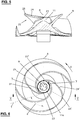
- Fig. 1 shows an impeller 10 for a centrifugal pump, for example as shown in FIG Fig. 9 is shown.
- the impeller 10 has a hub body 11 around which a plate 15 with two blades 20, 20 'is arranged.
- the hub body 11 is provided with a central bore 12 into which the drivable shaft 60 can be inserted at the rear and the end of a fastening screw 61 can be inserted at the front (cf. Fig. 9 ).
- the central bore 12 has a longitudinal groove 13 in which a bar on the shaft 60 can grip for the rotationally fixed connection.
- the plate 15 has a plate surface 16 on the front side which slopes continuously towards the periphery of the plate 15, preferably in a convex curvature.
- the two blades 20, 20 ′ are configured identically here and are arranged circumferentially offset by 180 degrees on the plate surface 16.
- the first blade 20 is explained in more detail below. The explanation applies in an analogous manner to the second blade 20 '.
- the blade 20 extends from the hub body 11 with a radially outward curvature and has a suction-side blade surface 21 and a pressure-side blade surface 22. As well as Fig. 2 shows, the blade surfaces 21, 22 are arranged inclined to the axis of rotation R of the impeller 10.
- leading edge 24 On the inlet side of the impeller 10, the transition from the blade surface 21 to the blade surface 22 is given by a leading edge 24. This extends from a hub contact point 23 on the hub body 11 to an apex 25. The leading edge 24 adjoins the end face 26 of the blade 20, which extends from the apex 25 to the trailing edge 27.
- the leading edge 24 here has a round profile (cf. in this regard in Fig. 2 the profile of the leading edge 24 'of the second blade 20' at the apex 25 ').
- the wall thickness of the blade 20 is reduced in the peripheral region of the plate 15 in that the blade surface 22 is beveled towards the blade surface 21.
- the trailing edge 27 is curved forward, ie in the direction of rotation D of the impeller 10 (cf. Fig. 2 ).
- the second blade 20 ' has the same structure as the first blade 20 and has the analogous elements 21'-27', which correspond to the elements 21-27 of the first blade 20.
- a level plane N is indicated, which is perpendicular to the axis of rotation R and is at the level of the hub contact point 23 or 23 '.
- the level plane N runs in the vicinity of the end face of the hub body 11, so that it only extends slightly above the level plane N.
- the leading edge 24, 24 ' rises from the hub contact point 23, 23' to the apex 25, 25 ', from where the end face 26, 26' drops, here below the level level N.
- the leading edge 24, 24 ' is strongly from inclined away from the axis of rotation R, so that the vertex 25, 25 'is closer to the level plane N than to the axis of rotation R.
- the angle of inclination ⁇ of the leading edge 23 with respect to the level plane N can be defined, for example, as follows, cf. Fig. 3-5 :
- A defines the axis which passes through the hub contact points 23 and 23 'and P the plane of projection which is perpendicular to the axis A and passes through the hub contact point 23.
- Rp defines the axis which lies in the projection plane P and runs parallel to the axis of rotation R of the impeller 10.
- the point 25p is the vertex 25 projected onto the projection plane P, in that it is rotated about the axis Rp until it comes to lie on the projection plane P.
- the points 25 and 25p thus have the same radial distance from the axis Rp.
- Lp defines the straight line that goes through the hub contact point 23 and the vertex 25p projected onto P. (Lp thus runs in the projection plane P.)
- the angle of inclination ⁇ is the angle between the level plane N and the straight line Lp and is selected to be greater than 0 degrees and less than 15 degrees. Preferably the angle is in the range of 5 to 10 degrees.
- the angle ⁇ can alternatively also be defined as the angle between the level plane N and the straight line L which goes through the hub contact point 23 and the vertex 25.
- the leading edge 24 ' is inclined with respect to the level plane N at an angle ⁇ , which is the angle between the level plane N and the straight line that goes through the hub contact point 23' and the vertex 25 '.
- the leading edge 24 lies on a surface of revolution which results when the straight line L is rotated about the axis Rp.
- the leading edge 24 thus lies on a cone with the tip at the hub contact point 23.
- the leading edge 24 ' lies on a cone with the tip at the hub contact point 23'.
- the plate 15 has a circular edge 17.
- the plate surface 16 is free of cutouts so that it extends all the way to the edge 17.
- the end face 11a of the hub body 11 has a circular edge with a diameter D1. This corresponds to the distance D1 between the two hub contact points 23 and 23 '.
- D1 is selected here to be relatively small in relation to the diameter D2 of the plate 15. Typically D1 is at most 30% of D2, preferably at most 25%, and / or at least 15% of D2; e.g. D1 is in the range of 20% -25% of D2.
- the leading edge 24, 24 ' is curved backwards when viewed in the radial direction, ie opposite to the direction of rotation D. Seen in the top view, the vertex 25, 25 'is thus arranged offset in relation to the hub contact point 23, 23' by an angle ⁇ in the circumferential direction of the axis of rotation R, cf. Fig. 6 .
- the angle y also called looping, is typically at least 90 degrees, preferably at least 100 degrees and / or at least 110 degrees.
- the angle of wrap of the entire blade 20, 20 ', ie from the hub contact point 23, 23' to the foremost end of the trailing edge 27, 27 ', when viewed from above, is at least 180 degrees, at least 200 degrees, at least 225 degrees, at least 250 degrees with increasing preference , at least 270 degrees.
- the leading edge 24, 24 'does not go perpendicularly away from the hub body 11, but hugs it as tangentially as possible.
- T defines the tangent of the leading edge 24 to the hub contact point 23.
- the axis A corresponds to the normal to the end face 11a of the hub body 11 in the plan view.
- the angle ⁇ between A and T is preferably selected to be greater than 60 degrees, particularly preferably greater than 70 degrees.
- leading edge 24 ' has an angle ⁇ , which is the angle between the tangent of the leading edge 24' to the hub contact point 23 'and the axis A.
- the impeller 10 shown here has back blades 40 on the rear of the plate 15, cf. Fig. 7 .
- a respective back vane 40 extends from the entry point 41 with a radial curvature to the exit point 42.
- the entry point 41 is arranged at a distance from the hub body 11.
- the exit point 42 is located here on the edge 17 of the plate 15.
- four back blades 40 are provided, each of which is evenly distributed in the circumferential direction of the axis of rotation R on the back of the plate 15.
- the number can also be chosen differently and can be, for example, one, two, three or more.
- Fig. 8 a further illustration of the impeller 10 together with part of an annular wear wall 50 is shown.
- the hub body 11 and the plate 15 of the impeller 10 are shown here in section, while the contour of the blades 20, 20 ', 40 is drawn, which is the free edge of a blade 20, 20', 40 seen in the side view during a rotation draws 360 degrees.
- the leading edges 24, 24 ', the end faces 26, 26' and the trailing edges 27, 27 'generate a profile which is defined by the lines 24r, 26r, 27r in FIG Fig. 8 is shown.
- 23r and 25r denote the point where the hub contact point 23, 23 'and the vertex 25, 25' come to lie.
- the leading edge 24, 24 ' is shaped here in such a way that the line 24r is straight.
- the wear wall 50 is arranged in a stationary manner.
- a gap which is preferably less than 2 mm, is provided between the contour line 26r and the wear wall 50.
- the impeller 10 can be produced in one piece, e.g. as a cast part, e.g. from cast iron or cast steel.
- the blades 20, 20 ' have undercuts.
- the arrangement and shape of the blades 20, 20 ′ are selected such that a sand casting mold can be created which enables the model to be removed from the mold.
- Fig. 9 shows the impeller 10 arranged in the pump housing 70, which is fastened to the shaft 60 by means of a screw 61.
- the head of the screw 61 is formed by a front plate 62 which rests against the end face of the hub body 11.
- the front plate 62 has a flat central region 62a which is surrounded by a rounded edge region 62b. This connects to the hub body 11.
- An annular wear wall 50 is also shown, which is replaceably attached to the inlet in the pump housing 70.
- the wear wall 50 has a round one Inside 51, which, viewed in the direction of flow, widens in diameter.
- the inside 51 is provided with grooves 52, here with three.
- grooves 52 extends from a starting point 52a, which is located adjacent to the inlet-side end of the inner side 51, with a curved, widening course to the end point 52b, which is located at the outlet-side end of the inner side 51.
- the curvature of a groove 52 is spiral-shaped here as seen in plan view.
- the widening of a groove 52 is V-shaped here.
- the pump housing 70 is in the Figures 12 and 13 more clearly visible. As an inlet, it has a suction connector 71 which is connected to the pressure connector 73 (outlet) via a spiral housing 72.
- the volute casing 72 is dimensioned such that the cross section increases in the direction of flow.
- the operation of the centrifugal pump is, for example, as follows:
- the suction nozzle 71 is connected to the suction line and the pressure nozzle 73 to the pressure line.
- the centrifugal pump which is not self-priming here, is filled with liquid.
- the shaft 11 is driven by means of a motor.
- the medium to be conveyed for example a liquid containing solids, is sucked in via the suction nozzle 71 and hits the impeller 10. Due to the special design of the inlet edges 24, 24 ', in particular, material that is flat and flexible will enter the area between the Shovels 20, 20 'made easier.
- the medium is conveyed by the impeller 10 along the spiral housing 72 and discharged via the pressure connection 73.
- one or more grooves 52 causes the centrifugal pump to clean itself.
- the rotation of the impeller 10 drives flat or elongated material to the periphery, for example, so that it gets between the grooves 52 and the impeller 10 and is gradually pulled through a groove 52 until it finally gets completely between the blades 20, 20 ' and is transported away.
- Impeller and centrifugal pumps as described here can be used in a variety of ways to convey different types of media, e.g. municipal and industrial wastewater, fiber-containing sludge, activated and return sludge and digested sludge as well as multi-phase mixtures with gas proportions that can also be high.
- media e.g. municipal and industrial wastewater, fiber-containing sludge, activated and return sludge and digested sludge as well as multi-phase mixtures with gas proportions that can also be high.
- an impeller is shown in which two blades 20, 20 ′ are arranged on the plate surface 16.
- the number of blades can also be different, e.g. three or more. If the number is lower, e.g. two or three, then large cross-sections can be provided between the blade surfaces so that even large solid bodies can pass through.
- the impeller can be changed by turning it, e.g. if the impeller is a cast part.
- the impeller is a cast part.
- grooves 52 are shown, in each of which the starting point 52a and end point 52b are arranged offset from one another both radially and circumferentially. It is also conceivable to design the grooves in such a way that they only run in the radial direction.
- the starting point of a groove is located, for example, at the starting point 52a of the groove 52, while the end point of the groove is arranged radially offset thereto. Analogous to that seen in plan view Fig. 10 the radial groove is thus straight.
Abstract
Das Laufrad (10) für eine Kreiselpumpe, mit welcher insbesondere feststoffhaltige Flüssigkeiten förderbar sind, umfasst einen Nabenkörper (11), einen Teller (15), welcher um den Nabenkörper herum angeordnet ist und vorderseitig eine Tellerfläche (16) aufweist, und Schaufeln (20, 20'), die auf der Tellerfläche angeordnet sind. Die jeweilige Schaufel weist eine Eintrittskante (24, 24') auf, die von einem Nabenanlagepunkt (23, 23') am Nabenkörper ausgehend zu einem Scheitelpunkt (25, 25') ansteigt und die in der Draufsicht gesehen entgegen der Drehrichtung (D) des Laufrades gekrümmt verläuft. Für die jeweilige Eintrittskante (24, 24') sind folgende Grössen gegeben:- eine Niveauebene N, welche senkrecht auf der Drehsachse (R) des Laufrades steht und in welcher der Nabenanlagepunkt der Eintrittskante liegt,- eine Gerade L, welche durch den Nabenanlagepunkt und den Scheitelpunkt der Eintrittskante hindurchgeht, und- einen Neigungswinkel (a) zwischen der Niveauebene N und der Geraden L, der grösser als 0 Grad und kleiner als 15 Grad gewählt ist.The impeller (10) for a centrifugal pump, with which liquids containing solids in particular can be conveyed, comprises a hub body (11), a plate (15) which is arranged around the hub body and has a plate surface (16) on the front, and blades (20) , 20 '), which are arranged on the plate surface. The respective blade has a leading edge (24, 24 ') which rises from a hub contact point (23, 23') on the hub body to an apex (25, 25 ') and which, when viewed from above, is opposite to the direction of rotation (D) of the The impeller is curved. The following parameters are given for the respective leading edge (24, 24 '): - a level plane N, which is perpendicular to the axis of rotation (R) of the impeller and in which the hub contact point of the leading edge lies, - a straight line L, which passes through the hub contact point and the vertex of the leading edge passes through, and an angle of inclination (a) between the level plane N and the straight line L, which is selected to be greater than 0 degrees and less than 15 degrees.
Description
Die vorliegende Erfindung bezieht sich auf ein Laufrad für eine Kreiselpumpe.The present invention relates to an impeller for a centrifugal pump.
Derartige Laufräder werden in Kreiselpumpen eingesetzt, um insbesondere feststoffhaltige Flüssigkeiten fördern zu können. Man ist bestrebt, zwischen den Schaufelflächen möglichst grosse Querschnitte vorzusehen, so dass auch grosse Festkörper hindurchgelangen können.Impellers of this type are used in centrifugal pumps in order to be able to convey liquids containing solids in particular. The aim is to provide the largest possible cross-sections between the blade surfaces so that large solid bodies can also pass through.
Allerdings können auch dann die Strömungsverhältnisse so sein, dass das Feststoffmaterial, z.B. wenn es in flexibler, flächiger Form vorliegt, nicht über die Eintrittskante einer Schaufel hinweg gelangt, sondern an der Eintrittskante haften bleibt und vom Laufrad lediglich herumgewirbelt wird. Hierbei kommt es vor dem Laufrad zu einer Anballung von derartigem Material, bis die Pumpe schliesslich gänzlich verstopft ist.However, the flow conditions can also be such that the solid material, e.g. if it is in a flexible, flat form, does not get over the leading edge of a blade, but rather sticks to the leading edge and is only whirled around by the impeller. Such material accumulates in front of the impeller until the pump is finally completely clogged.
Es ist eine Aufgabe der Erfindung, ein Laufrad anzugeben, welches einer Verstopfung in einer Kreiselpumpe entgegenwirkt.It is an object of the invention to provide an impeller which counteracts clogging in a centrifugal pump.
Ein Laufrad, das diese Aufgabe löst, ist im Anspruch 1 angegeben. Die weiteren Ansprüche geben bevorzugte Ausführungen des Laufrades sowie eine Kreiselpumpe mit einem Laufrad an.An impeller that solves this problem is specified in claim 1. The further claims indicate preferred designs of the impeller and a centrifugal pump with an impeller.
Gemäss Anspruch 1 umfasst das Laufrad Schaufeln, deren Eintrittskanten jeweils von einem Nabenanlagepunkt ausgehend zu einem Scheitelpunkt ansteigen, in der Draufsicht gesehen entgegen der Drehrichtung des Laufrades gekrümmt verlaufen und einen Neigungswinkel von kleiner als 15 Grad aufweisen. Die Formgebung der Schaufel erleichtert den Eintritt von insbesondere flexiblem, flächigen Material in das Laufrad, so dass die Gefahr einer Verstopfung reduziert ist. Das Laufrad ist so gestaltbar, dass die Schaufeln ausgeprägte Flächen aufweisen, so dass entsprechend eine gute Pumpwirkung erzielbar ist.According to claim 1, the impeller comprises blades, the leading edges of which rise from a hub contact point to an apex, are curved against the direction of rotation of the impeller when viewed from above and have an angle of inclination of less than 15 degrees. The shape of the blade facilitates the entry of particularly flexible, flat material into the impeller, so that the risk of clogging is reduced. The impeller can be designed in such a way that the blades have pronounced surfaces so that a correspondingly good pumping effect can be achieved.
Vorzugsweise ist beim Laufrad für die jeweilige Eintrittskante eine Achse A gegeben, welche durch den Nabenanlagepunkt und die Drehachse des Laufrades hindurchgeht und welche senkrecht auf dieser Drehachse steht, wobei die Eintrittskante quer zur Achse A weggeht, so dass die durch den Nabenanlagepunkt gehende Tangente (T) an die Eintrittskante einen Winkel (ε) zur Achse A aufweist, der im Bereich 45 Grad bis 90 Grad liegt, vorzugsweise im Bereich 60 Grad bis 90 Grad, besonders bevorzugt im Bereich 70 Grad bis 90 Grad.In the case of the impeller, there is preferably an axis A for the respective leading edge which passes through the hub contact point and the axis of rotation of the impeller and which is perpendicular to this axis of rotation, the leading edge going away transversely to axis A, so that the tangent (T ) at the leading edge has an angle (ε) to the axis A, which is in the range of 45 degrees to 90 Degrees, preferably in the
Vorzugsweise ist eine Kreiselpumpe mit einem Laufrad und mit einer Wandung vorgesehen, welche innenseitig Nuten aufweist. Diese können in der Draufsicht gesehen gerade oder gekrümmt verlaufen. Die Nuten begünstigen zusätzlich den Durchtritt von flexiblem, flächigen Material, so dass dieses wegbefördert wird und es dadurch zu einer Selbstreinigung der Kreiselpumpe kommt. Es ist nicht nötig, eine Schneideinrichtung vorzusehen, welche das Material zerkleinert.A centrifugal pump is preferably provided with an impeller and with a wall which has grooves on the inside. When viewed from above, these can be straight or curved. The grooves also facilitate the passage of flexible, flat material, so that this is carried away and the centrifugal pump is thereby self-cleaning. It is not necessary to provide a cutting device which shreds the material.
Die Erfindung wird im Folgenden anhand von Ausführungsbeispielen unter Bezugnahme auf Figuren erläutert. Es zeigen
-
Fig. 1 ein Ausführungsbeispiel eines Laufrads in einer perspektivischen Ansicht; -
Fig. 2 das Laufrad gemässFig. 1 in einer ersten Seitenansicht; -
Fig. 3 das Laufrad gemässFig. 1 in einer zweiten Seitenansicht; -
Fig. 4 das Laufrad gemässFig. 1 in einer Draufsicht; -
Fig. 5 das Laufrad gemässFig. 1 geschnitten in der Ebene V-V gemässFig. 6 ; -
Fig. 6 dieselbe Draufsicht wie inFig. 4 ; -
Fig. 7 das Laufrad gemässFig. 1 in einer Unteransicht; -
Fig. 8 das Laufrad gemässFig. 1 zusammen mit einem Teil einer Schleisswand in einer teilweise geschnittenen Seitenansicht, wobei jedoch von den Schaufeln die Kontur zu sehen ist, welche diese beim Drehen beschreiben; -
Fig. 9 einen Teil einer Kreiselpumpe mit einem Laufrad gemässFig. 1 in einer geschnittenen Seitenansicht; -
Fig. 10 die Schleisswand aus der Kreiselpumpe gemässFig. 9 in einer Draufsicht; -
Fig. 11 die Schleisswand gemässFig. 10 in einer perspektivischen Ansicht; -
Fig. 12 das Pumpengehäuse der Kreiselpumpe gemässFig. 9 ; und -
Fig. 13 das Pumpengehäuse gemässFig. 12 in einer teilweise geschnitten Draufsicht gemäss der Linie XIII-XIII.
-
Fig. 1 an embodiment of an impeller in a perspective view; -
Fig. 2 the impeller according toFig. 1 in a first side view; -
Fig. 3 the impeller according toFig. 1 in a second side view; -
Fig. 4 the impeller according toFig. 1 in a plan view; -
Fig. 5 the impeller according toFig. 1 cut in level VV according toFig. 6 ; -
Fig. 6 same plan view as inFig. 4 ; -
Fig. 7 the impeller according toFig. 1 in a bottom view; -
Fig. 8 the impeller according toFig. 1 together with part of a wear wall in a partially sectioned side view, but the contour of the blades can be seen which they describe when turning; -
Fig. 9 a part of a centrifugal pump with an impeller according toFig. 1 in a sectional side view; -
Fig. 10 the wear wall from the centrifugal pump according toFig. 9 in a plan view; -
Fig. 11 the Schleisswand according toFig. 10 in a perspective view; -
Fig. 12 the pump housing of the centrifugal pump according toFig. 9 ; and -
Fig. 13 the pump housing according toFig. 12 in a partially sectioned plan view along the line XIII-XIII.
Der Teller 15 weist vorderseitig eine Tellerfläche 16 auf, die zur Peripherie des Tellers 15 hin kontinuierlich abfällt, vorzugsweise in einer konvexen Krümmung.The
Die beiden Schaufeln 20, 20' sind hier gleich ausgestaltet und um 180 Grad umfänglich versetzt auf der Tellerfläche 16 angeordnet. Nachfolgend wird die erste Schaufel 20 genauer erläutert. Die Erläuterung gilt in analoger Weise für die zweite Schaufel 20'.The two
Die Schaufel 20 erstreckt sich vom Nabenkörper 11 mit einer Krümmung radial nach aussen und weist eine saugseitge Schaufelfläche 21 und eine druckseitige Schaufelfläche 22 auf. Wie auch
Einlassseitig des Laufrades 10 ist der Übergang von der Schaufelfläche 21 zur Schaufelfläche 22 durch eine Eintrittskante 24 gegeben. Diese erstreckt sich von einem Nabenanlagepunkt 23 am Nabenkörper 11 zu einem Scheitelpunkt 25. Der Eintrittskante 24 schliesst sich die Stirnseite 26 der Schaufel 20 an, welche sich vom Scheitelpunkt 25 zur Austrittskante 27 erstreckt.On the inlet side of the
Die Eintrittskante 24 weist hier ein rundes Profil auf (vgl. dazu in
Die zweite Schaufel 20' ist gleich aufgebaut wie die erste Schaufel 20 und weist die analogen Elemente 21'-27' auf, welche den Elementen 21-27 der ersten Schaufel 20 entsprechen.The second blade 20 'has the same structure as the
In
Der Neigungswinkel α der Eintrittskante 23 gegenüber der Niveauebene N ist z.B. wie folgt definierbar, vgl.
Lp definiert die Gerade, welche durch den Nabenanlagepunkt 23 und den auf P projizierten Scheitelpunkt 25p geht. (Lp verläuft somit in der Projektionsebene P.) Der Neigungswinkel α ist der Winkel zwischen der Niveauebene N und der Geraden Lp und ist grösser als 0 Grad und kleiner als 15 Grad gewählt. Vorzugsweise liegt der Winkel im Bereich von 5 bis 10 Grad.Lp defines the straight line that goes through the
Der Winkel α kann alternativ auch als Winkel zwischen der Niveauebene N und der Geraden L definiert werden, welche durch den Nabenanlagepunkt 23 und den Scheitelpunkt 25 geht.The angle α can alternatively also be defined as the angle between the level plane N and the straight line L which goes through the
Analog ist die Eintrittskante 24' gegenüber der Niveauebene N mit einem Winkel α geneigt, welcher der Winkel zwischen der Niveauebene N und der Geraden ist, die durch den Nabenanlagepunkt 23' und den Scheitelpunkt 25' geht.Analogously, the leading edge 24 'is inclined with respect to the level plane N at an angle α, which is the angle between the level plane N and the straight line that goes through the hub contact point 23' and the vertex 25 '.
Im vorliegenden Ausführungsbeispiel liegt die Eintrittskante 24 auf einer Rotationsfläche welche sich beim Drehen der Geraden L um die Achse Rp ergibt. Die Eintrittskante 24 liegt somit auf einem Konus mit der Spitze beim Nabenanlagepunkt 23. Analog liegt die Eintrittskante 24' auf einem Konus mit der Spitze beim Nabenanlagepunkt 23'.In the present exemplary embodiment, the leading
Wie die Draufsicht in
Die Stirnseite 11a des Nabenköpers 11 weist einen kreisrunden Rand mit Durchmesser D1 auf. Dieser entsprechend dem Abstand D1 zwischen den beiden Nabenanlagepunkten 23 und 23'. D1 ist hier relativ klein in Bezug auf den Durchmesser D2 des Tellers 15 gewählt. Typischerweise ist D1 höchstens 30 % von D2, vorzugsweise höchstens 25 %, und/oder mindestens 15 % von D2; z.B. ist D1 im Bereich von 20 %-25 % von D2.The
Die Eintrittskante 24, 24' ist in radialer Richtung gesehen rückwärts, d.h. entgegen der Drehrichtung D, gekrümmt. In der Draufsicht gesehen ist der Scheitelpunkt 25, 25' somit in Bezug auf den Nabenanlagepunkt 23, 23' um einen Winkel γ in Umfangsrichtung der Rotationsachse R versetzt angeordnet, vgl.
Der Umschlingungswinkel der ganzen Schaufel 20, 20', d.h. vom Nabenanlagepunkt 23, 23' bis zum vordersten Ende der Austrittskante 27, 27' beträgt in der Draufsicht gesehen in steigender Bevorzugung mindestens 180 Grad, mindestens 200 Grad, mindestens 225 Grad, mindestens 250 Grad, mindestens 270 Grad.The angle of wrap of the
In der Draufsicht gesehen, geht die Eintrittskante 24, 24' nicht senkrecht vom Nabenkörper 11 weg, sondern schmiegt sich diesem möglichst tangential an. T definiert die Tangente der Eintrittskante 24 an den Nabenanlagepunkt 23. Die Achse A entspricht der Normalen auf die Stirnseite 11a des Nabenkörpers 11 in der Draufsicht. Der Winkel ε zwischen A und T ist vorzugsweise grösser als 60 Grad gewählt, besonders bevorzugt grösser als 70 Grad.Seen in the top view, the leading
Analog weist die Eintrittskante 24' einen Winkel ε auf, welcher der Winkel zwischen der Tangente der Eintrittskante 24' an den Nabenanlagepunkt 23' und der Achse A ist.Analogously, the leading edge 24 'has an angle ε, which is the angle between the tangent of the leading edge 24' to the hub contact point 23 'and the axis A.
Um die Resultierende der Axialkräfte, welche im Betrieb auf das Laufrad 10 wirken, zu verringern, weist das hier dargestellte Laufrad 10 rückseitig des Tellers 15 Rückenschaufeln 40 auf, vgl.
In
Die Eintrittskante 24, 24' ist hier so geformt, dass die Linie 24r gerade ist.The leading
Die Schleisswand 50 ist stationär angeordnet. Zwischen der Konturlinie 26r und der Schleisswand 50 ist ein Spalt vorgesehen, der vorzugsweise weniger als 2 mm beträgt.The
Das Laufrad 10 ist einteilig z.B. als Gussteil herstellbar, z.B. aus Gusseisen oder Stahlguss. In der Draufsicht gesehen weisen die Schaufeln 20, 20' Hinterschneidungen auf. Jedoch sind Anordnung und Form der Schaufeln 20, 20' so gewählt, dass eine Sandgussform erstellt werden kann, die eine Entformung des Modells ermöglicht.The
Weiter ist eine ringförmige Schleisswand 50 dargestellt, welche auswechselbar im Einlass in das Pumpengehäuse 70 angebracht ist. Die Schleisswand 50 weist eine runde Innenseite 51 auf, die sich in Strömungsrichtung gesehen im Durchmesser aufweitet. Wie
Das Pumpengehäuse 70 ist in den
Der Betrieb der Kreiselpumpe ist z.B. wie folgt:
Der Saugstutzen 71 wird mit der Saugleitung und der Druckstutzen 73 mit der Druckleitung verbunden. Die Kreiselpumpe, welche hier nicht selbstansaugend ist, wird mit Flüssigkeit gefüllt. Die Welle 11 wird mittels eines Motors angetrieben. Das zu fördernde Medium, z.B. eine feststoffhaltige Flüssigkeit, wird via den Saugstutzen 71 angesaugt und trifft auf das Laufrad 10. Aufgrund der besonderen Ausgestaltung der Eintrittskanten 24, 24' wird insbesondere Material, das flächig und flexibel ist, der Eintritt in den Bereich zwischen den Schaufeln 20, 20' erleichtert. Das Medium wird durch das Laufrad 10 entlang dem Spiralgehäuse 72 gefördert und via den Druckstutzen 73 abgeleitet.The operation of the centrifugal pump is, for example, as follows:
The
Das Vorsehen einer oder mehrerer Nuten 52 bewirkt eine Selbstreinigung der Kreiselpumpe. Durch die Drehung des Laufrades 10 wird z.B. flächiges oder längliches Material an die Peripherie getrieben, so dass es zwischen die Nuten 52 und dem Laufrad 10 gelangt und allmählich durch eine Nut 52 hindurchgezogen wird, bis es schliesslich vollständig zwischen die Schaufeln 20, 20' gelangt und wegtransportiert wird.The provision of one or
Laufrad und Kreiselpumpe wie hier beschrieben sind vielfältig einsetzbar, um Medien verschiedener Art zu fördern, z.B. kommunale und industrielle Abwässer, faserhaltige Schlämme, Belebt- und Rücklaufschlämme sowie Faulschlämme als auch Mehrphasengemische mit Gasanteilen, die auch hoch sein können.Impeller and centrifugal pumps as described here can be used in a variety of ways to convey different types of media, e.g. municipal and industrial wastewater, fiber-containing sludge, activated and return sludge and digested sludge as well as multi-phase mixtures with gas proportions that can also be high.
Aus der vorangehenden Beschreibung sind dem Fachmann zahlreiche Abwandlungen zugänglich, ohne den Schutzbereich der Erfindung zu verlassen, der durch die Ansprüche definiert ist.Numerous modifications are accessible to the person skilled in the art from the preceding description without departing from the scope of protection of the invention, which is defined by the claims.
In den Figuren ist ein Laufrad dargestellt, bei welchem zwei Schaufeln 20, 20' auf der Tellerfläche 16 angeordnet sind. Die Anzahl der Schaufeln kann auch anders sein und z.B. drei oder mehr betragen. Ist die Anzahl geringer, z.B. zwei oder drei, so sind zwischen den Schaufelflächen grosse Querschnitte bereitstellbar, so dass auch grosse Festkörper hindurchgelangen können.In the figures, an impeller is shown in which two
Bei Bedarf kann das Laufrad durch Abdrehen verändert werden, z.B. dann, wenn das Laufrad als Gussteil vorliegt. Vorzugsweise werden beim Abdrehen nur die Schaufeln 20, 20' an der Peripherie abgedreht, so dass die jeweilige Austrittskante näher bei der Drehachse zu liegen kommt, währenddessen der Teller 15 mit dem ursprünglichen Aussendurchmesser belassen wird.If necessary, the impeller can be changed by turning it, e.g. if the impeller is a cast part. When turning, only the
In
Claims (15)
einen Nabenkörper (11),
einen Teller (15), welcher um den Nabenkörper herum angeordnet ist und vorderseitig eine Tellerfläche (16) aufweist, und
Schaufeln (20, 20'), die auf der Tellerfläche angeordnet sind,
wobei die jeweilige Schaufel eine Eintrittskante (24, 24') aufweist, die von einem Nabenanlagepunkt (23, 23') am Nabenkörper ausgehend zu einem Scheitelpunkt (25, 25') ansteigt und die in der Draufsicht gesehen entgegen der Drehrichtung (D) des Laufrades gekrümmt verläuft, und wobei für die jeweilige Eintrittskante (24, 24') folgende Grössen gegeben sind:
a hub body (11),
a plate (15) which is arranged around the hub body and has a plate surface (16) on the front side, and
Blades (20, 20 ') which are arranged on the plate surface,
wherein the respective blade has a leading edge (24, 24 ') which rises from a hub contact point (23, 23') on the hub body to an apex (25, 25 ') and which, when viewed from above, is opposite to the direction of rotation (D) of the The impeller is curved, and the following values are given for the respective leading edge (24, 24 '):
Applications Claiming Priority (1)
| Application Number | Priority Date | Filing Date | Title |
|---|---|---|---|
| CH00695/20A CH717512A1 (en) | 2020-06-11 | 2020-06-11 | Impeller for a centrifugal pump. |
Publications (1)
| Publication Number | Publication Date |
|---|---|
| EP3922855A1 true EP3922855A1 (en) | 2021-12-15 |
Family
ID=71105204
Family Applications (1)
| Application Number | Title | Priority Date | Filing Date |
|---|---|---|---|
| EP21178554.8A Withdrawn EP3922855A1 (en) | 2020-06-11 | 2021-06-09 | Rotor for a centrifugal pump |
Country Status (2)
| Country | Link |
|---|---|
| EP (1) | EP3922855A1 (en) |
| CH (1) | CH717512A1 (en) |
Families Citing this family (1)
| Publication number | Priority date | Publication date | Assignee | Title |
|---|---|---|---|---|
| WO2024058737A1 (en) * | 2022-09-15 | 2024-03-21 | Eys Metal Sanayi Ve Ticaret Limited Sirketi | A novel impeller design for submersible centrifugal wastewater pumps |
Citations (5)
| Publication number | Priority date | Publication date | Assignee | Title |
|---|---|---|---|---|
| US4594052A (en) * | 1982-02-08 | 1986-06-10 | A. Ahlstrom Osakeyhtio | Centrifugal pump for liquids containing solid material |
| US4900335A (en) * | 1987-09-03 | 1990-02-13 | Scanpump Ab | Centrifugal pump wheel and method of pumping gas containing liquid by means of a centrifugal pump |
| JPH0396698A (en) * | 1989-09-06 | 1991-04-22 | Asahi Kogyo Kk | Circulating pump |
| US6139260A (en) * | 1997-12-18 | 2000-10-31 | Itt Manufacturing Enterprises, Inc. | Pump having a pump housing with one or more feeding grooves |
| JP4963836B2 (en) * | 2006-01-31 | 2012-06-27 | 株式会社クボタ | Centrifugal pump device |
-
2020
- 2020-06-11 CH CH00695/20A patent/CH717512A1/en not_active Application Discontinuation
-
2021
- 2021-06-09 EP EP21178554.8A patent/EP3922855A1/en not_active Withdrawn
Patent Citations (5)
| Publication number | Priority date | Publication date | Assignee | Title |
|---|---|---|---|---|
| US4594052A (en) * | 1982-02-08 | 1986-06-10 | A. Ahlstrom Osakeyhtio | Centrifugal pump for liquids containing solid material |
| US4900335A (en) * | 1987-09-03 | 1990-02-13 | Scanpump Ab | Centrifugal pump wheel and method of pumping gas containing liquid by means of a centrifugal pump |
| JPH0396698A (en) * | 1989-09-06 | 1991-04-22 | Asahi Kogyo Kk | Circulating pump |
| US6139260A (en) * | 1997-12-18 | 2000-10-31 | Itt Manufacturing Enterprises, Inc. | Pump having a pump housing with one or more feeding grooves |
| JP4963836B2 (en) * | 2006-01-31 | 2012-06-27 | 株式会社クボタ | Centrifugal pump device |
Also Published As
| Publication number | Publication date |
|---|---|
| CH717512A1 (en) | 2021-12-15 |
Similar Documents
| Publication | Publication Date | Title |
|---|---|---|
| DE69620635T2 (en) | PUMP WHEEL WITH SEPARATED, SLITTED RODS | |
| EP3779201B1 (en) | Scraper element for the leading edges of impellers of waste water pumps | |
| DE10327574B4 (en) | Impeller for a fuel pump | |
| DE602004006301T2 (en) | CENTRIFUGAL PUMP | |
| EP2226505B1 (en) | Free flow impeller with cutting edges | |
| EP2888484B1 (en) | Pump for transporting waste water and wheel and floor panel for same | |
| EP2643595B1 (en) | Self cleaning radial flow pump with recirculation behind the impeller | |
| EP0623752B1 (en) | Centrifugal pump impeller | |
| DE112004001198T5 (en) | Impeller blade assembly for a centrifugal pump | |
| DE102004058458B3 (en) | Pump with axial impeller e.g. for pump, has screw-shaped wings for sucking in liquid by inlet port arranged at lower surface of axial impeller with wings at lower surface have cutting edge | |
| EP3922855A1 (en) | Rotor for a centrifugal pump | |
| EP2348220B1 (en) | Immersion pump | |
| EP0733805A1 (en) | Fibres repelling wall-shape design | |
| EP0874161A1 (en) | Centrifugal pump | |
| EP0750119B1 (en) | Pump impeller | |
| DE10024741B4 (en) | Side channel pump | |
| EP2497956A1 (en) | Free flow pump | |
| EP1344944B1 (en) | Centrifugal pump with crushing device | |
| DE60311165T2 (en) | Centrifugal pump for low flow rates with improved suction height | |
| EP3559475B1 (en) | Vortex pump | |
| EP1039140B1 (en) | Feed pump | |
| EP0623750B1 (en) | Pump of the axial type | |
| DE10305726A1 (en) | Centrifugal pump with shredding device | |
| DE7718084U1 (en) | CENTRIFUGAL PUMP | |
| DE102021110936A1 (en) | Pump impeller, casing member and pump herewith |
Legal Events
| Date | Code | Title | Description |
|---|---|---|---|
| PUAI | Public reference made under article 153(3) epc to a published international application that has entered the european phase |
Free format text: ORIGINAL CODE: 0009012 |
|
| STAA | Information on the status of an ep patent application or granted ep patent |
Free format text: STATUS: THE APPLICATION HAS BEEN PUBLISHED |
|
| AK | Designated contracting states |
Kind code of ref document: A1 Designated state(s): AL AT BE BG CH CY CZ DE DK EE ES FI FR GB GR HR HU IE IS IT LI LT LU LV MC MK MT NL NO PL PT RO RS SE SI SK SM TR |
|
| B565 | Issuance of search results under rule 164(2) epc |
Effective date: 20211015 |
|
| STAA | Information on the status of an ep patent application or granted ep patent |
Free format text: STATUS: THE APPLICATION IS DEEMED TO BE WITHDRAWN |
|
| 18D | Application deemed to be withdrawn |
Effective date: 20220616 |