EP3917700B1 - Kokillenplatte - Google Patents
Kokillenplatte Download PDFInfo
- Publication number
- EP3917700B1 EP3917700B1 EP20707544.1A EP20707544A EP3917700B1 EP 3917700 B1 EP3917700 B1 EP 3917700B1 EP 20707544 A EP20707544 A EP 20707544A EP 3917700 B1 EP3917700 B1 EP 3917700B1
- Authority
- EP
- European Patent Office
- Prior art keywords
- insert
- cooling
- mould plate
- fastening
- plate according
- Prior art date
- Legal status (The legal status is an assumption and is not a legal conclusion. Google has not performed a legal analysis and makes no representation as to the accuracy of the status listed.)
- Active
Links
Images

Classifications
-
- B—PERFORMING OPERATIONS; TRANSPORTING
- B22—CASTING; POWDER METALLURGY
- B22D—CASTING OF METALS; CASTING OF OTHER SUBSTANCES BY THE SAME PROCESSES OR DEVICES
- B22D11/00—Continuous casting of metals, i.e. casting in indefinite lengths
- B22D11/04—Continuous casting of metals, i.e. casting in indefinite lengths into open-ended moulds
- B22D11/055—Cooling the moulds
-
- B—PERFORMING OPERATIONS; TRANSPORTING
- B22—CASTING; POWDER METALLURGY
- B22D—CASTING OF METALS; CASTING OF OTHER SUBSTANCES BY THE SAME PROCESSES OR DEVICES
- B22D11/00—Continuous casting of metals, i.e. casting in indefinite lengths
- B22D11/10—Supplying or treating molten metal
- B22D11/11—Treating the molten metal
- B22D11/112—Treating the molten metal by accelerated cooling
-
- B—PERFORMING OPERATIONS; TRANSPORTING
- B22—CASTING; POWDER METALLURGY
- B22D—CASTING OF METALS; CASTING OF OTHER SUBSTANCES BY THE SAME PROCESSES OR DEVICES
- B22D11/00—Continuous casting of metals, i.e. casting in indefinite lengths
- B22D11/12—Accessories for subsequent treating or working cast stock in situ
- B22D11/124—Accessories for subsequent treating or working cast stock in situ for cooling
Definitions
- the invention relates to a mold plate having the features in the preamble of patent claim 1.
- the thermal stress on copper molds during continuous casting can lead to significant material stresses within the copper alloy, particularly in thin slab continuous casters. Mold plates are exposed to extreme heat on their hot side facing the melt, ie the casting side, while the rear side facing the cooling water remains largely cold. Within the mold plate, which is a few millimeters thick, there is a temperature gradient of several 100 Kelvin between the hot side and the water-cooled rear. This leads to different thermal expansions in the thickness profile from the cast side to the back. The pouring side is trying to expand, but at the same time it is being hit by the cooling water facing back is prevented from expanding. This results in high internal material stresses. If the internal material stresses exceed the elastic limit of the copper alloy, this leads to plastic deformation of the cast side, known as bulging.
- the plastic deformation also causes a gap to form between the broad and narrow sides of a mold.
- Liquid steel can penetrate into the resulting gap between the narrow side and the broad side of a mold. This can lead to damage to the mold plates during width adjustment.
- the strand shell can tear open below the mold in the outer corner area of the slab.
- the attachment points of the mold plates to the rear support plates or the so-called water tanks are arranged at a small distance from one another and are provided in a relatively large number.
- the fastening points which are arranged at a short distance from one another, specify a certain course of the cooling channel.
- the heat dissipation can exhibit undesired inhomogeneities over the entire hot side. Inhomogeneous heat dissipation in turn causes material stresses during casting, particularly in the meniscus area of the mold plate. The material stresses can be so high that plastic deformation occurs. In extreme cases, the copper alloy can even soften.
- there is the fundamental risk of elastic deformation of the mold plate caused by the temperature gradient between the hot and cold sides of the mold plate.
- At least one cooling channel should extend from the point of view of a fastening point to the support plate or to the water tank of the casting side of the mold plate opposite the back to below the fastening point. This can improve cooling in the base area of the attachment points.
- the JP 2006 320 925 A discloses an additional cooling channel below a mounting point.
- the attachment point serves to receive a fastening bolt for connecting a mold plate to a support plate.
- the externally adjacent cooling ducts are not widened so that they extend under the attachment point, but rather another cooling duct is created below the attachment point.
- the production is comparatively complex.
- the DE 10 2004 001 928 A1 discloses a liquid-cooled mold for the continuous casting of metals, wherein the mold plates are connected to a support structure by means of fastening bolts.
- the mold plates or the mold tube and the supporting structure are connected to one another without jamming, with a working gap being present between the supporting structure and the mold plate or the mold tube.
- the working gap is located on the side of the attachment points and in particular on the side of a threaded insert arranged there, which is part of the attachment point or forms it.
- the invention is based on the object of demonstrating a mold plate in which the risk of bulging is reduced. Deformation of the mold plate during continuous casting should be minimized.
- the mold plate according to the invention has a casting side and a rear side facing away from the casting side.
- the mold plate consists of a copper alloy. It can be assembled with other concrete plates to form a mould, as is used in the continuous casting of molten metal.
- At least one cooling channel open to the rear is arranged in the rear. It has a cooling surface that faces the casting side.
- An insert is positioned within the cooling channel to form a cooling gap between an inner surface of the insert and the cooling surface. In the casting operation, cooling water is conducted through this cooling gap in order to cool the mold plate via the cooling surface and thus also the casting side.
- the insert is connected to attachment points in the cooling surface via attachment bolts.
- the area of the cooling surface can also be referred to as the slot bottom of a cooling system.
- the invention does not rule out the presence of other connection points between the insert and the mold plate.
- the use is exclusively via the attachment points in the cooling surface, i. H. connected to the mold plate within the cooling channel.
- the inserts are not connected to the mold plate in the area of the cooling surface, but outside the area of the cooling surface.
- Fixing points are arranged in the area of the walls of the cooling channels, via which the mold plate can be screwed to a load-bearing steel support plate or to a water box.
- the points for connecting the mold plate to the support plate are referred to as fixing points while the points for connecting the insert with the in this invention Mold plate are referred to as attachment points.
- the connection is made in the same way, namely via the fastening bolts or fixing bolts, ie via screw connections.
- the fastening bolts can be arranged as stay bolts on the mold plate, so that nuts have to be screwed onto the fastening bolts. Conversely, however, it can also be a matter of fastening bolts which have a screw head and are screwed into threaded receptacles at the fastening points or fixing points. Mixed constellations of stud bolts and screw bolts are possible.
- the main advantage of the arrangement of the attachment points according to the invention is that the inserts, which are supported on the back of the support plate anyway, are not only used to determine the cross section of the cooling gaps and to increase the flow rate, but rather contribute to plastic deformations caused by bulging to prevent in the area of the cooling gap.
- the attachment points or the attachment in the area of the cooling surface improves the dimensional stability of the entire mold plate during casting, particularly when a large number of attachment points are provided. At least as many fastening points are preferably provided as there are fixing points.
- the doubling of the number of connection points (attachment points including fixing points) means that the mold plate is extremely stiff without having to increase the wall thickness of the mold plate on the casting side.
- the attachment points are, in particular, island-like elevations in relation to the cooling surface.
- the cooling surface is preferably a substantially planar surface. Within the cooling surface, individual webs be arranged facing the inner surface of the insert. The individual cooling gaps through which cooling water flows are formed between these webs or the cooling surface and the inner surface.
- the attachment points are preferably located in the area of the webs, so that the respective cooling gap can continue to run essentially straight.
- the individual webs in the cooling surface also preferably run straight and parallel to one another, ie in the longitudinal direction of the respective cooling channel.
- Two or three webs are preferably arranged within a cooling channel. Depending on the number of bars, there are fastening points in the area of each bar within a cooling channel.
- the spacing of the attachment points in the transverse direction of the channel therefore corresponds to the spacing of the webs.
- the distances are each related to the center distance. Preferably there are two transversely spaced attachment points.
- the island-like elevations in the cooling surface also have the advantage that the attachment does not take place via an intervention in the cooling surface, but via attachment points on the cooling surface.
- the thickness of the mold plate between the casting side and the cooling surface in the area of the attachment points is at least not smaller than in the other areas of this cooling channel. There is therefore no material weakness in the area of the attachment points.
- This in turn has advantages with regard to the power transmission and also advantages with regard to the homogenization of the heat transfer. The material reserve for reworking the casting side is retained.
- the thickness of the mold plate below the cooling surface does not vary too much.
- no hotspots should arise, ie points in which the heat dissipation is reduced.
- such hotspots could arise in the case of very large, island-like elevations, since the cooling water does not reach the core area of an island-like elevation.
- the heat dissipation below such an attachment point could therefore be reduced.
- at least one cooling gap extends from the point of view of the attachment point to the casting side below the attachment point.
- the attachment point is somewhat undercut. The undercut can be on one or both sides.
- the undercut should be designed in such a way that the web also runs below the attachment point with the same width and/or height, while the attachment point itself only begins above the web. As a result, the web below the attachment point is cooled in the same way as outside the attachment point. There are no hotspots. The heat dissipation remains uniform and homogeneous over the entire length of the web.
- the plurality of attachment points are preferably offset from one another not only in the longitudinal direction, but also in the transverse direction of the cooling channel. As explained above, they are in particular in an aligned arrangement in relation to the respective webs.
- the attachment points of two adjacent webs do not necessarily have to be in the same length section, i. H. be arranged directly next to each other in the transverse direction. In particular, they can be offset from one another in the longitudinal direction. Based on two webs, the result is an arrangement of attachment points that not only entails an increase in the number of attachment points in the transverse direction, but also in the longitudinal direction.
- the respective attachment points are located at a distance from the attachment points via which the mold plate is attached to the support plate, particularly viewed in the longitudinal direction.
- the attachment points can be arranged, for example, in a zigzag pattern or trapezoidal pattern. The aim is to ensure that the thin-walled mold plate is supported as evenly as possible in the area of the cooling channel. If necessary, individual attachment points can be set at the same height, i. H. be arranged in the same length section.
- the inserts are supported on the support plate in the installed position. They therefore have, at least in sections, a height or thickness in their edge region on supporting projections, which extends over the entire depth of the cooling channel from the back of the mold plate to the cooling surface.
- rear support projections which reach to the rear of the mold plate, are preferably arranged in the longitudinal section of the cooling channel in which there is a fastening point. This allows the mold plate directly over the webs or the attachment points on the support plate arranged at the rear. If the inserts overlap a web delimiting the cooling channel or, in general, a wall of the cooling channel, the insert can absorb tensile forces that arise as a result of thermal expansion in the cast side. The mold cannot be lifted off the insert due to the fastening point in the cooling channel and this in turn cannot be shifted in the direction of the casting side because it is supported on the web or the wall.
- the supporting projections can overlap the webs or the wall.
- the supporting projections have a dual function in that they absorb tensile and compressive forces and, depending on the position (front of the supporting plate/rear of the web) of the adjacent surfaces, can transfer them to adjacent components (mold plate, supporting plate).
- the supporting projections are directly opposite one another on both longitudinal sides of an insert, specifically at the level of a fastening point. If the attachment points are very close together, i. H. in the case of fastening points which are a small distance apart in the longitudinal direction, the supporting projections can merge with one another or a single, correspondingly wide supporting projection can be provided.
- the forces acting at the attachment points can be introduced uniformly on the left and right side of the insert from the mold plate via the insert into the rear support plate.
- the area between two directly opposite supporting projections is designed as a thickened yoke, in which one or two fastening bolts are arranged. Therefore, the insert between the longitudinally opposite supporting projections preferably has a greater thickness than the areas arranged in the longitudinal direction next to the supporting projections. Due to the greater thickness, the insert is more resistant to bending in the area of the fastening bolts or in the area of the fastening points.
- connection between the mold plate and the insert is designed so that the mold plate due to the high thermal Influences is not prevented from expanding under casting conditions.
- this can be achieved by arranging a working gap between the mold plate and the insert in the area of the attachment point.
- the working gap is very small.
- the mold plate is mounted in a floating manner relative to the insert at the fastening points.
- the attachment point, ie the mold plate should be displaceable transversely to the cooling channel, ie laterally in the longitudinal direction and transverse direction of the cooling channel, without jamming.
- the floating mounting is not to be understood in such a way that the mold plate tends to bulge due to the additional degrees of freedom and is therefore exposed to plastic deformation.
- the fastening bolt is therefore located in a sufficiently large through hole, which is so large that the mold plate with the fastening bolt arranged thereon can move laterally to the insert, but only to a limited extent perpendicularly to the insert.
- the position of the insert relative to the mold plate is fixed by the system on the back of the support plate.
- the fastening bolt is screwed to the fastening point with the incorporation of a screw-locking element.
- the screw locking element is supported on a sleeve that is located between a bolt head and the attachment point.
- the fastening bolt forms a unit with the sleeve and the screw locking element, as well as the mold plate, with this unit being laterally displaceable relative to the insert.
- the through-hole in which the fastening bolt is arranged preferably has a gradation in diameter, so that there is a contact surface for the bolt head or a collar of a sleeve which points out and on which the bolt head is supported.
- the contact surface in combination with a working gap defines the degree of freedom of the mold plate perpendicular to the cooling surface. A minimal gap is already sufficient here to allow lateral displacement of the mold plate relative to the insert without increasing the risk of bulging.
- the width of the working gap is preferably less than 0.2 mm.
- the working gap is not designed as a coolant channel within the meaning of the invention, but has a much smaller width.
- the working gap can be set differently, and the arrangement and the number of fastening points can also be varied in order to achieve cooling that is as homogeneous as possible and constant rigidity of the mold plate.
- the expression "jamming-free connection between the mold plate and the insert” is to be understood in such a way that only slight material stresses arise in the copper material of the mold plate when it shifts longitudinally or transversely to the insert due to thermal influences. Touching the insert and the attachment point with low coefficients of friction are not critical. Only jamming blockages due to high prestressing between the insert and the mold plate in this area should preferably be avoided.
- the bolt heads of the fastening bolts are arranged completely countersunk in a stepped through hole in the insert.
- the somewhat greater thickness of the inserts in the area of the through-holes is due to the fact that the supporting projections are arranged along the length of the insert and the insert should have high torsional rigidity between the fastening points and the supporting projections.
- the insert acts as a yoke in this area.
- this does not mean that particularly long bolts must be used.
- the bolt heads can be arranged countersunk completely in the through hole.
- the through hole preferably has gradations from both sides.
- the bolt head can be countersunk in the through hole.
- the through hole has a contact surface in the form of an inwardly directed collar.
- the island-like raised fastening point is arranged on the opposite side of the through-bore or the collar.
- the attachment point preferably fully engages the insert a. There is a sufficiently wide gap on the peripheral side of the attachment point, so that the mold plate can be displaced laterally with respect to the through-hole.
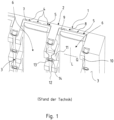
- the figure 1 shows the state of the art and serves to explain the technological background. It is not an embodiment for which protection is sought.
- the invention is based on one in the figure 2 purely schematically illustrated embodiment explained in more detail.
- the figure 1 shows a perspective view of a portion of a mold plate 1, partially in section.
- the reference numerals that explain the mold plate 1 of figure 1 are used for essentially the same content components in the mold plate 1 according to the invention figure 2 further used.
- the mold plate 1 of figure 1 has a pouring side facing away from the viewer and a back 2 facing the viewer. In the installed position, the back 2 is supported on a support plate, not shown.
- hot melt on the casting side 2 is to be cooled in that heat is absorbed by the mold plate 1 and is dissipated via cooling water that is passed through cooling gaps 4 , which in turn are located within cooling channels 5 .
- the casting direction in this mold plate 1 corresponds to the vertical direction.
- the cooling channels 5 therefore extend parallel to the casting direction from top to bottom. They run parallel to each other.
- the inserts 6 are configured in a U-shape in cross section. Its inner surface 7 facing the cooling gaps 4 bears against webs 8 which point from a cooling surface 9 of the cooling channels 5 in the direction of the rear side 3 of the mold plate 1 .
- the webs 8 determine the height of the cooling gaps 4. The distance between the webs 8 determines the width of the cooling gaps 4 and thus overall the cross-sectional area of the cooling gaps 4. A high pressure prevails in the cooling gaps 4 during the casting operation.
- the inserts 6 are therefore supported during operation on a support plate, not shown in detail.
- the inserts 6 are on their long sides contoured and have supporting projections 11, which are profiled towards the longitudinal side in such a way that they are adapted to the contour of the walls of the cooling channels 5, so that the inserts 6 are position-oriented both in the longitudinal direction L and in the transverse direction Q within the cooling channels 5.
- the inserts 6 can only be removed from the cooling channels 5 towards the back 3 .
- Two adjacent cooling channels 5 are separated from one another by webs 12 .
- the webs are twelve fixing points 13 at a distance from one another. They have threaded inserts 14, via which the mold plate 1 together with the inserts 6 can be screwed to the support plate to be arranged on the back. As a result, the respective insert 6 is also precisely positioned and held within the cooling channels.
- the mold plate 1 according to the invention has the essential difference that 5 fastening points 15 with threaded inserts 16 are arranged on the respective cooling surfaces 9 of the cooling channels.
- the fastening points 15 point to the back 3 of the mold plate 1.
- Fastening bolts 17 are arranged in through holes 18 in the respective insert 6 and are screwed into the threaded inserts 16 of the fastening points 15.
- the bolt head 21 of the fastening bolt 17 rests on the fastening point 15 via a sleeve 19 and a screw locking element 20 .
- a collar 22 in the through hole 18 is held between the attachment point 15 and the sleeve 19 with play.
- the diameter of the through hole 18 is dimensioned so large in all its length range that a small lateral displacement of the attachment point 15 relative to use 6 can be done. In this way, thermally induced stresses between the insert 6 and the mold plate 1 are avoided.
- the attachment points 15 are each located in the area of the webs 8. Since there are two webs 8 at a parallel distance from one another, there are two rows of attachment points 15. The attachment points 15 of the adjacent rows are offset from one another in the longitudinal direction L of the cooling channel 5. Since the webs 8, which limit the cooling gaps 4, approximately at equal intervals are arranged to each other, the respective attachment points 15 are approximately the same distance from a left and a right wall of the respective channel 5 and thus approximately the same distance from the fixing points 13 arranged there. This results in a high density of attachment points 15 or fixing points 13, via which the mold plate 1 can be connected to the inserts 6 or a support plate.
- the attachment points 15 are island-like elevations. You start at a distance from the cooling surface 17, ie where the webs 8 end. Since the attachment points 15 have a greater width than the webs 8, the attachment points 15 are undercut when viewed perpendicularly from the back to the casting side. The respective adjacent cooling gap 4 extends below the respective attachment point 15, but only as far as the width of the web 18 specifies. In the sectional view of the figure 2 the attachment points 15 appear as laterally constricted. These constrictions below the attachment points 15 therefore have the form of segments which are diametrically opposed and are separated from one another by the web. The web 8 is, so to speak, the connecting link between the attachment point 15 and the cooling surface 9.
- the through bores 18 are located between two diametrically arranged supporting projections 10 which are each arranged on a longitudinal side of the insert 6 .
- the support projections 10,11 are used, as in the embodiment of the prior art, for rearward support of the inserts 6 on the support plate, not shown in detail.
- the wider support projections 11 are located where the respective insert 6 has a greater thickness than the adjacent areas of the insert 6 in the longitudinal direction L. Other areas mean those longitudinal sections in which there are no attachment points 15 or through-holes 18.
- the thicker areas between the opposing, wider supporting projections 10 serve as a yoke and are intended to absorb forces that are exerted on the inserts 6 by the mold plate 1 in the area of the cooling surface 9 and via the fastening points 15 .
- the areas between said support projections 10 are particularly rigid and solid. In the other areas where the inserts 6 only have the function of limiting the cooling gaps 4, but without absorbing forces via additional attachment points 15, do not require such massive support. Accordingly, the supporting projections 11 there are dimensioned to be smaller in cross section.
- the inserts 6 can absorb not only forces acting from the webs 8 on the cooling surface 9 in the direction of the inserts 6 and transmit them to the support plate, but also absorb forces pointing in the opposite direction.
- the supporting projections 10 overlap the web 12 between two cooling channels 5. In this area, the insert 6 is wider than the cooling channel 5.
- the web 12 has a somewhat lower height in this area.
- the supporting projection 10 does not protrude beyond the rear side 3, but ends in the same plane as the fixing points 13 and the other areas of the web 12. If there is no web, as in the case of a cooling channel 5 at the edge, the supporting projection 10 can move into a rear Take pocket 23, which is a recess in the back 3. The supporting projection 10 therefore does not protrude beyond the back 3 .
- the mold plate 1 according to the invention Due to the large number of attachment points 15 between the inserts 6, the mold plate 1 according to the invention has a higher flexural rigidity in order to avoid plastic deformations due to thermal influences. Compared to the prior art, the homogeneity of the heat dissipation is maintained.
Landscapes
- Engineering & Computer Science (AREA)
- Mechanical Engineering (AREA)
- Continuous Casting (AREA)
- Molds, Cores, And Manufacturing Methods Thereof (AREA)
- Moulds For Moulding Plastics Or The Like (AREA)
Priority Applications (1)
| Application Number | Priority Date | Filing Date | Title |
|---|---|---|---|
| RS20230669A RS64564B1 (sr) | 2019-01-30 | 2020-01-08 | Kalupna ploča |
Applications Claiming Priority (2)
| Application Number | Priority Date | Filing Date | Title |
|---|---|---|---|
| DE102019102313.0A DE102019102313B3 (de) | 2019-01-30 | 2019-01-30 | Kokillenplatte |
| PCT/DE2020/100005 WO2020156607A1 (de) | 2019-01-30 | 2020-01-08 | Kokillenplatte |
Publications (3)
| Publication Number | Publication Date |
|---|---|
| EP3917700A1 EP3917700A1 (de) | 2021-12-08 |
| EP3917700B1 true EP3917700B1 (de) | 2023-07-05 |
| EP3917700C0 EP3917700C0 (de) | 2023-07-05 |
Family
ID=69742620
Family Applications (1)
| Application Number | Title | Priority Date | Filing Date |
|---|---|---|---|
| EP20707544.1A Active EP3917700B1 (de) | 2019-01-30 | 2020-01-08 | Kokillenplatte |
Country Status (13)
| Country | Link |
|---|---|
| US (1) | US11383292B2 (https=) |
| EP (1) | EP3917700B1 (https=) |
| JP (1) | JP7105400B2 (https=) |
| KR (1) | KR102392933B1 (https=) |
| CN (1) | CN113348043B (https=) |
| DE (1) | DE102019102313B3 (https=) |
| ES (1) | ES2955012T3 (https=) |
| MX (1) | MX391424B (https=) |
| MY (1) | MY197206A (https=) |
| PL (1) | PL3917700T3 (https=) |
| RS (1) | RS64564B1 (https=) |
| WO (1) | WO2020156607A1 (https=) |
| ZA (1) | ZA202105340B (https=) |
Family Cites Families (10)
| Publication number | Priority date | Publication date | Assignee | Title |
|---|---|---|---|---|
| RU2106928C1 (ru) * | 1996-04-08 | 1998-03-20 | Акционерное общество "Новолипецкий металлургический комбинат" | Кристаллизатор для непрерывной разливки металлов |
| MXPA01002885A (es) * | 2000-03-25 | 2003-08-20 | Sms Demag Ag | Coquilla de placa enfriada por liquido. |
| DE10237472A1 (de) * | 2002-08-16 | 2004-02-26 | Km Europa Metal Ag | Flüssigkeitsgekühlte Kokille |
| DE102004001928A1 (de) | 2004-01-14 | 2005-08-04 | Km Europa Metal Ag | Flüssigkeitsgekühlte Kokille |
| JP2006320925A (ja) | 2005-05-18 | 2006-11-30 | Sanyo Special Steel Co Ltd | 均一冷却によって鋳片疵を防止する連続鋳造用鋳型 |
| JP4611350B2 (ja) * | 2007-06-28 | 2011-01-12 | 三島光産株式会社 | 連続鋳造用鋳型 |
| JP4808196B2 (ja) * | 2007-08-31 | 2011-11-02 | 三島光産株式会社 | 連続鋳造用鋳型 |
| CN201168770Y (zh) * | 2008-04-03 | 2008-12-24 | 钢铁研究总院 | 一种组合冷却式板坯结晶器铜板 |
| CN204997021U (zh) | 2015-09-15 | 2016-01-27 | 西峡龙成特种材料有限公司 | 一种散热面积大的金属连铸用液冷结晶器 |
| DE102016124801B3 (de) | 2016-12-19 | 2017-12-14 | Kme Germany Gmbh & Co. Kg | Kokillenplatte und Kokille |
-
2019
- 2019-01-30 DE DE102019102313.0A patent/DE102019102313B3/de active Active
-
2020
- 2020-01-08 WO PCT/DE2020/100005 patent/WO2020156607A1/de not_active Ceased
- 2020-01-08 MY MYPI2021004112A patent/MY197206A/en unknown
- 2020-01-08 MX MX2021008501A patent/MX391424B/es unknown
- 2020-01-08 EP EP20707544.1A patent/EP3917700B1/de active Active
- 2020-01-08 PL PL20707544.1T patent/PL3917700T3/pl unknown
- 2020-01-08 JP JP2021549423A patent/JP7105400B2/ja active Active
- 2020-01-08 US US17/417,274 patent/US11383292B2/en active Active
- 2020-01-08 RS RS20230669A patent/RS64564B1/sr unknown
- 2020-01-08 CN CN202080008230.6A patent/CN113348043B/zh active Active
- 2020-01-08 ES ES20707544T patent/ES2955012T3/es active Active
- 2020-01-08 KR KR1020217027185A patent/KR102392933B1/ko active Active
-
2021
- 2021-07-28 ZA ZA2021/05340A patent/ZA202105340B/en unknown
Also Published As
| Publication number | Publication date |
|---|---|
| JP7105400B2 (ja) | 2022-07-25 |
| WO2020156607A1 (de) | 2020-08-06 |
| ES2955012T3 (es) | 2023-11-28 |
| KR102392933B1 (ko) | 2022-05-03 |
| US11383292B2 (en) | 2022-07-12 |
| PL3917700T3 (pl) | 2023-10-23 |
| CN113348043A (zh) | 2021-09-03 |
| MX2021008501A (es) | 2022-04-07 |
| RS64564B1 (sr) | 2023-10-31 |
| JP2022516385A (ja) | 2022-02-25 |
| EP3917700A1 (de) | 2021-12-08 |
| CN113348043B (zh) | 2023-05-30 |
| DE102019102313B3 (de) | 2020-06-04 |
| ZA202105340B (en) | 2022-04-28 |
| EP3917700C0 (de) | 2023-07-05 |
| US20220143682A1 (en) | 2022-05-12 |
| MY197206A (en) | 2023-05-31 |
| MX391424B (es) | 2025-03-19 |
| KR20210110402A (ko) | 2021-09-07 |
Similar Documents
| Publication | Publication Date | Title |
|---|---|---|
| EP0468607B2 (de) | Flüssigkeitsgekühlte Kokille für das Stranggiessen von Metallen | |
| EP1398099B1 (de) | Flüssigkeitsgekühlte Kokille zum Stranggiessen von Metallen | |
| EP3487650B1 (de) | Kokillenplatte und kokille | |
| EP3283245B1 (de) | Gestützte rohrkokille für knüppel- und vorblockanlagen | |
| EP1555073B1 (de) | Flüssigkeitsgekühlte Stranggiesskokille | |
| EP3523069B1 (de) | Kokillenteiler zum einbau in eine kokille | |
| EP1499462A1 (de) | Anpassung des wärmeüberganges bei stranggiesskokillen, insbesondere im giessspiegelbereich | |
| EP3917700B1 (de) | Kokillenplatte | |
| EP1332811B1 (de) | Kokillenrohr | |
| EP2083957B1 (de) | Stranggiesskokille | |
| DE4444941C2 (de) | Stranggießkokille | |
| EP1736257B1 (de) | Flüssigkeitsgekühlte Kokille zum Stranggiessen von Metallen | |
| EP4043122B1 (de) | Druckgussmaschine mit verbesserter aufspannplatte | |
| DE102023112607B3 (de) | Kokille | |
| EP2483017B1 (de) | Giessform | |
| EP1506826A1 (de) | Stranggiesskokille | |
| EP1757385B1 (de) | Kokillenbreitseite einer Trichterkokille | |
| DE2616487A1 (de) | Verfahren und vorrichtung zum kontinuierlichen giessen eines stahlstranges in form einer rechteckfoermigen bramme | |
| DE2615228A1 (de) | Stranggussform | |
| EP1025929A1 (de) | Anordnung zum Verbinden einer Kokillenplatte mit einem Wasserkasten | |
| AT522037B1 (de) | Kokilleneinheit zum Stranggießen von Metallprodukten sowie Stranggießanlage | |
| EP1452253B1 (de) | Optimierte Befestigung von Kokillenplatten | |
| EP3461570A1 (de) | Stranggiesskokille | |
| DE10247122A1 (de) | Zylinderkurbelgehäuse mit Kühlmantel für eine Verbrennungskraftmaschine | |
| EP1519028A1 (de) | Zylinderkopf einer Brennkraftmaschine |
Legal Events
| Date | Code | Title | Description |
|---|---|---|---|
| STAA | Information on the status of an ep patent application or granted ep patent |
Free format text: STATUS: UNKNOWN |
|
| STAA | Information on the status of an ep patent application or granted ep patent |
Free format text: STATUS: THE INTERNATIONAL PUBLICATION HAS BEEN MADE |
|
| PUAI | Public reference made under article 153(3) epc to a published international application that has entered the european phase |
Free format text: ORIGINAL CODE: 0009012 |
|
| STAA | Information on the status of an ep patent application or granted ep patent |
Free format text: STATUS: REQUEST FOR EXAMINATION WAS MADE |
|
| 17P | Request for examination filed |
Effective date: 20210526 |
|
| AK | Designated contracting states |
Kind code of ref document: A1 Designated state(s): AL AT BE BG CH CY CZ DE DK EE ES FI FR GB GR HR HU IE IS IT LI LT LU LV MC MK MT NL NO PL PT RO RS SE SI SK SM TR |
|
| DAV | Request for validation of the european patent (deleted) | ||
| DAX | Request for extension of the european patent (deleted) | ||
| RAP1 | Party data changed (applicant data changed or rights of an application transferred) |
Owner name: KME SPECIAL PRODUCTS & SOLUTIONS GMBH |
|
| GRAP | Despatch of communication of intention to grant a patent |
Free format text: ORIGINAL CODE: EPIDOSNIGR1 |
|
| STAA | Information on the status of an ep patent application or granted ep patent |
Free format text: STATUS: GRANT OF PATENT IS INTENDED |
|
| INTG | Intention to grant announced |
Effective date: 20230323 |
|
| RAP3 | Party data changed (applicant data changed or rights of an application transferred) |
Owner name: CUNOVA GMBH |
|
| GRAS | Grant fee paid |
Free format text: ORIGINAL CODE: EPIDOSNIGR3 |
|
| GRAA | (expected) grant |
Free format text: ORIGINAL CODE: 0009210 |
|
| STAA | Information on the status of an ep patent application or granted ep patent |
Free format text: STATUS: THE PATENT HAS BEEN GRANTED |
|
| AK | Designated contracting states |
Kind code of ref document: B1 Designated state(s): AL AT BE BG CH CY CZ DE DK EE ES FI FR GB GR HR HU IE IS IT LI LT LU LV MC MK MT NL NO PL PT RO RS SE SI SK SM TR |
|
| REG | Reference to a national code |
Ref country code: CH Ref legal event code: EP |
|
| REG | Reference to a national code |
Ref country code: AT Ref legal event code: REF Ref document number: 1584364 Country of ref document: AT Kind code of ref document: T Effective date: 20230715 |
|
| REG | Reference to a national code |
Ref country code: DE Ref legal event code: R096 Ref document number: 502020004038 Country of ref document: DE |
|
| REG | Reference to a national code |
Ref country code: IE Ref legal event code: FG4D Free format text: LANGUAGE OF EP DOCUMENT: GERMAN |
|
| REG | Reference to a national code |
Ref country code: RO Ref legal event code: EPE |
|
| U01 | Request for unitary effect filed |
Effective date: 20230802 |
|
| U07 | Unitary effect registered |
Designated state(s): AT BE BG DE DK EE FI FR IT LT LU LV MT NL PT SE SI Effective date: 20230808 |
|
| REG | Reference to a national code |
Ref country code: LT Ref legal event code: MG9D |
|
| REG | Reference to a national code |
Ref country code: ES Ref legal event code: FG2A Ref document number: 2955012 Country of ref document: ES Kind code of ref document: T3 Effective date: 20231128 |
|
| REG | Reference to a national code |
Ref country code: SK Ref legal event code: T3 Ref document number: E 42461 Country of ref document: SK |
|
| PG25 | Lapsed in a contracting state [announced via postgrant information from national office to epo] |
Ref country code: GR Free format text: LAPSE BECAUSE OF FAILURE TO SUBMIT A TRANSLATION OF THE DESCRIPTION OR TO PAY THE FEE WITHIN THE PRESCRIBED TIME-LIMIT Effective date: 20231006 |
|
| PG25 | Lapsed in a contracting state [announced via postgrant information from national office to epo] |
Ref country code: IS Free format text: LAPSE BECAUSE OF FAILURE TO SUBMIT A TRANSLATION OF THE DESCRIPTION OR TO PAY THE FEE WITHIN THE PRESCRIBED TIME-LIMIT Effective date: 20231105 |
|
| PG25 | Lapsed in a contracting state [announced via postgrant information from national office to epo] |
Ref country code: NO Free format text: LAPSE BECAUSE OF FAILURE TO SUBMIT A TRANSLATION OF THE DESCRIPTION OR TO PAY THE FEE WITHIN THE PRESCRIBED TIME-LIMIT Effective date: 20231005 Ref country code: IS Free format text: LAPSE BECAUSE OF FAILURE TO SUBMIT A TRANSLATION OF THE DESCRIPTION OR TO PAY THE FEE WITHIN THE PRESCRIBED TIME-LIMIT Effective date: 20231105 Ref country code: HR Free format text: LAPSE BECAUSE OF FAILURE TO SUBMIT A TRANSLATION OF THE DESCRIPTION OR TO PAY THE FEE WITHIN THE PRESCRIBED TIME-LIMIT Effective date: 20230705 Ref country code: GR Free format text: LAPSE BECAUSE OF FAILURE TO SUBMIT A TRANSLATION OF THE DESCRIPTION OR TO PAY THE FEE WITHIN THE PRESCRIBED TIME-LIMIT Effective date: 20231006 |
|
| U20 | Renewal fee for the european patent with unitary effect paid |
Year of fee payment: 5 Effective date: 20240125 |
|
| REG | Reference to a national code |
Ref country code: DE Ref legal event code: R097 Ref document number: 502020004038 Country of ref document: DE |
|
| PG25 | Lapsed in a contracting state [announced via postgrant information from national office to epo] |
Ref country code: SM Free format text: LAPSE BECAUSE OF FAILURE TO SUBMIT A TRANSLATION OF THE DESCRIPTION OR TO PAY THE FEE WITHIN THE PRESCRIBED TIME-LIMIT Effective date: 20230705 |
|
| PLBE | No opposition filed within time limit |
Free format text: ORIGINAL CODE: 0009261 |
|
| STAA | Information on the status of an ep patent application or granted ep patent |
Free format text: STATUS: NO OPPOSITION FILED WITHIN TIME LIMIT |
|
| 26N | No opposition filed |
Effective date: 20240408 |
|
| PG25 | Lapsed in a contracting state [announced via postgrant information from national office to epo] |
Ref country code: MC Free format text: LAPSE BECAUSE OF FAILURE TO SUBMIT A TRANSLATION OF THE DESCRIPTION OR TO PAY THE FEE WITHIN THE PRESCRIBED TIME-LIMIT Effective date: 20230705 |
|
| PG25 | Lapsed in a contracting state [announced via postgrant information from national office to epo] |
Ref country code: MC Free format text: LAPSE BECAUSE OF FAILURE TO SUBMIT A TRANSLATION OF THE DESCRIPTION OR TO PAY THE FEE WITHIN THE PRESCRIBED TIME-LIMIT Effective date: 20230705 |
|
| REG | Reference to a national code |
Ref country code: CH Ref legal event code: PL |
|
| PG25 | Lapsed in a contracting state [announced via postgrant information from national office to epo] |
Ref country code: CH Free format text: LAPSE BECAUSE OF NON-PAYMENT OF DUE FEES Effective date: 20240131 |
|
| PG25 | Lapsed in a contracting state [announced via postgrant information from national office to epo] |
Ref country code: CH Free format text: LAPSE BECAUSE OF NON-PAYMENT OF DUE FEES Effective date: 20240131 |
|
| PG25 | Lapsed in a contracting state [announced via postgrant information from national office to epo] |
Ref country code: IE Free format text: LAPSE BECAUSE OF NON-PAYMENT OF DUE FEES Effective date: 20240108 |
|
| PG25 | Lapsed in a contracting state [announced via postgrant information from national office to epo] |
Ref country code: IE Free format text: LAPSE BECAUSE OF NON-PAYMENT OF DUE FEES Effective date: 20240108 |
|
| U20 | Renewal fee for the european patent with unitary effect paid |
Year of fee payment: 6 Effective date: 20250127 |
|
| PG25 | Lapsed in a contracting state [announced via postgrant information from national office to epo] |
Ref country code: CY Free format text: LAPSE BECAUSE OF FAILURE TO SUBMIT A TRANSLATION OF THE DESCRIPTION OR TO PAY THE FEE WITHIN THE PRESCRIBED TIME-LIMIT; INVALID AB INITIO Effective date: 20200108 |
|
| PG25 | Lapsed in a contracting state [announced via postgrant information from national office to epo] |
Ref country code: HU Free format text: LAPSE BECAUSE OF FAILURE TO SUBMIT A TRANSLATION OF THE DESCRIPTION OR TO PAY THE FEE WITHIN THE PRESCRIBED TIME-LIMIT; INVALID AB INITIO Effective date: 20200108 |
|
| PGFP | Annual fee paid to national office [announced via postgrant information from national office to epo] |
Ref country code: MK Payment date: 20241226 Year of fee payment: 6 |
|
| PGFP | Annual fee paid to national office [announced via postgrant information from national office to epo] |
Ref country code: PL Payment date: 20251230 Year of fee payment: 7 |
|
| PGFP | Annual fee paid to national office [announced via postgrant information from national office to epo] |
Ref country code: SK Payment date: 20251229 Year of fee payment: 7 |
|
| PGFP | Annual fee paid to national office [announced via postgrant information from national office to epo] |
Ref country code: RS Payment date: 20251226 Year of fee payment: 7 |
|
| U20 | Renewal fee for the european patent with unitary effect paid |
Year of fee payment: 7 Effective date: 20260126 |
|
| PGFP | Annual fee paid to national office [announced via postgrant information from national office to epo] |
Ref country code: GB Payment date: 20260126 Year of fee payment: 7 |
|
| PGFP | Annual fee paid to national office [announced via postgrant information from national office to epo] |
Ref country code: ES Payment date: 20260210 Year of fee payment: 7 |
|
| PGFP | Annual fee paid to national office [announced via postgrant information from national office to epo] |
Ref country code: RO Payment date: 20260108 Year of fee payment: 7 |
|
| PGFP | Annual fee paid to national office [announced via postgrant information from national office to epo] |
Ref country code: TR Payment date: 20260105 Year of fee payment: 7 |
|
| PGFP | Annual fee paid to national office [announced via postgrant information from national office to epo] |
Ref country code: CZ Payment date: 20251231 Year of fee payment: 7 |