EP3914494B1 - Verfahren zum betrieb eines spurführungssystems und spurführungssystem - Google Patents
Verfahren zum betrieb eines spurführungssystems und spurführungssystem Download PDFInfo
- Publication number
- EP3914494B1 EP3914494B1 EP20701928.2A EP20701928A EP3914494B1 EP 3914494 B1 EP3914494 B1 EP 3914494B1 EP 20701928 A EP20701928 A EP 20701928A EP 3914494 B1 EP3914494 B1 EP 3914494B1
- Authority
- EP
- European Patent Office
- Prior art keywords
- touch
- guidance system
- lane guidance
- steering handle
- sensor
- Prior art date
- Legal status (The legal status is an assumption and is not a legal conclusion. Google has not performed a legal analysis and makes no representation as to the accuracy of the status listed.)
- Active
Links
Images

Classifications
-
- B—PERFORMING OPERATIONS; TRANSPORTING
- B62—LAND VEHICLES FOR TRAVELLING OTHERWISE THAN ON RAILS
- B62D—MOTOR VEHICLES; TRAILERS
- B62D15/00—Steering not otherwise provided for
- B62D15/02—Steering position indicators ; Steering position determination; Steering aids
- B62D15/025—Active steering aids, e.g. helping the driver by actively influencing the steering system after environment evaluation
-
- B—PERFORMING OPERATIONS; TRANSPORTING
- B60—VEHICLES IN GENERAL
- B60W—CONJOINT CONTROL OF VEHICLE SUB-UNITS OF DIFFERENT TYPE OR DIFFERENT FUNCTION; CONTROL SYSTEMS SPECIALLY ADAPTED FOR HYBRID VEHICLES; ROAD VEHICLE DRIVE CONTROL SYSTEMS FOR PURPOSES NOT RELATED TO THE CONTROL OF A PARTICULAR SUB-UNIT
- B60W30/00—Purposes of road vehicle drive control systems not related to the control of a particular sub-unit, e.g. of systems using conjoint control of vehicle sub-units
- B60W30/10—Path keeping
- B60W30/12—Lane keeping
-
- B—PERFORMING OPERATIONS; TRANSPORTING
- B60—VEHICLES IN GENERAL
- B60W—CONJOINT CONTROL OF VEHICLE SUB-UNITS OF DIFFERENT TYPE OR DIFFERENT FUNCTION; CONTROL SYSTEMS SPECIALLY ADAPTED FOR HYBRID VEHICLES; ROAD VEHICLE DRIVE CONTROL SYSTEMS FOR PURPOSES NOT RELATED TO THE CONTROL OF A PARTICULAR SUB-UNIT
- B60W50/00—Details of control systems for road vehicle drive control not related to the control of a particular sub-unit, e.g. process diagnostic or vehicle driver interfaces
- B60W50/08—Interaction between the driver and the control system
- B60W50/14—Means for informing the driver, warning the driver or prompting a driver intervention
-
- B—PERFORMING OPERATIONS; TRANSPORTING
- B60—VEHICLES IN GENERAL
- B60W—CONJOINT CONTROL OF VEHICLE SUB-UNITS OF DIFFERENT TYPE OR DIFFERENT FUNCTION; CONTROL SYSTEMS SPECIALLY ADAPTED FOR HYBRID VEHICLES; ROAD VEHICLE DRIVE CONTROL SYSTEMS FOR PURPOSES NOT RELATED TO THE CONTROL OF A PARTICULAR SUB-UNIT
- B60W50/00—Details of control systems for road vehicle drive control not related to the control of a particular sub-unit, e.g. process diagnostic or vehicle driver interfaces
- B60W50/08—Interaction between the driver and the control system
- B60W50/14—Means for informing the driver, warning the driver or prompting a driver intervention
- B60W50/16—Tactile feedback to the driver, e.g. vibration or force feedback to the driver on the steering wheel or the accelerator pedal
-
- B—PERFORMING OPERATIONS; TRANSPORTING
- B60—VEHICLES IN GENERAL
- B60W—CONJOINT CONTROL OF VEHICLE SUB-UNITS OF DIFFERENT TYPE OR DIFFERENT FUNCTION; CONTROL SYSTEMS SPECIALLY ADAPTED FOR HYBRID VEHICLES; ROAD VEHICLE DRIVE CONTROL SYSTEMS FOR PURPOSES NOT RELATED TO THE CONTROL OF A PARTICULAR SUB-UNIT
- B60W60/00—Drive control systems specially adapted for autonomous road vehicles
- B60W60/005—Handover processes
-
- B—PERFORMING OPERATIONS; TRANSPORTING
- B62—LAND VEHICLES FOR TRAVELLING OTHERWISE THAN ON RAILS
- B62D—MOTOR VEHICLES; TRAILERS
- B62D15/00—Steering not otherwise provided for
- B62D15/02—Steering position indicators ; Steering position determination; Steering aids
- B62D15/029—Steering assistants using warnings or proposing actions to the driver without influencing the steering system
-
- B—PERFORMING OPERATIONS; TRANSPORTING
- B60—VEHICLES IN GENERAL
- B60W—CONJOINT CONTROL OF VEHICLE SUB-UNITS OF DIFFERENT TYPE OR DIFFERENT FUNCTION; CONTROL SYSTEMS SPECIALLY ADAPTED FOR HYBRID VEHICLES; ROAD VEHICLE DRIVE CONTROL SYSTEMS FOR PURPOSES NOT RELATED TO THE CONTROL OF A PARTICULAR SUB-UNIT
- B60W50/00—Details of control systems for road vehicle drive control not related to the control of a particular sub-unit, e.g. process diagnostic or vehicle driver interfaces
- B60W50/02—Ensuring safety in case of control system failures, e.g. by diagnosing, circumventing or fixing failures
- B60W50/0205—Diagnosing or detecting failures; Failure detection models
- B60W2050/0215—Sensor drifts or sensor failures
-
- B—PERFORMING OPERATIONS; TRANSPORTING
- B60—VEHICLES IN GENERAL
- B60W—CONJOINT CONTROL OF VEHICLE SUB-UNITS OF DIFFERENT TYPE OR DIFFERENT FUNCTION; CONTROL SYSTEMS SPECIALLY ADAPTED FOR HYBRID VEHICLES; ROAD VEHICLE DRIVE CONTROL SYSTEMS FOR PURPOSES NOT RELATED TO THE CONTROL OF A PARTICULAR SUB-UNIT
- B60W50/00—Details of control systems for road vehicle drive control not related to the control of a particular sub-unit, e.g. process diagnostic or vehicle driver interfaces
- B60W50/02—Ensuring safety in case of control system failures, e.g. by diagnosing, circumventing or fixing failures
- B60W50/029—Adapting to failures or work around with other constraints, e.g. circumvention by avoiding use of failed parts
- B60W2050/0295—Inhibiting action of specific actuators or systems
Definitions
- the present invention relates to a method for operating a lane guidance system and an associated lane guidance system of a vehicle.
- Modern motor vehicles have tracking systems that are set up to steer a vehicle independently, with many driving situations requiring a user to take over control of the vehicle using a steering handle. If, in the case of an active lane guidance system, a user touch on the steering handle cannot be detected within a predetermined time window, then the lane guidance system is deactivated and activated again when touched.
- the DE 10 2010 022 433 A1 discloses a method in which an indication to take control of the vehicle is issued to a driver. In the event that no driver takeover is detected, the automatically working assistance system is switched off and the hazard warning lights are activated at the same time.
- the U.S. 9,475,521 B1 discloses a lane departure warning system in which a malfunction of the touch sensors on the steering wheel can be determined and the assistance systems associated with it can then be switched off or blocked. Touch sensor malfunction is verified using torque or steering angle sensors. By evaluating the signals from the touch sensors and the torque or steering angle sensors, it is determined whether a missing signal from the touch sensors is caused by a malfunction or by the driver not touching it.
- the DE 10 2013 009423 A1 discloses a method for operating a vehicle tracking system with a steering handle comprising a touch-sensitive sensor, by means of which a hands-off situation of the driver can be identified.
- a hand-off detection a A warning is issued and, if necessary, a warning escalation is initiated if there is no reaction to the warning.
- a sensor If a sensor is defective, it does not deliver a sensor signal and the absence of the sensor signal is interpreted as the vehicle user being unwilling to control the vehicle.
- the object is achieved by a method for operating a tracking system having the features of claim 1 and a tracking system according to claim 8.
- the lane guidance system is set up to steer independently.
- the lane guidance system includes, for example, environment sensors such as cameras, radar, lidar for detecting the environment and the course of the road, a computing unit for data evaluation and actuators for controlling the steering system.
- the tracking system is preferably coupled to a longitudinal control system, so that autonomous or semi-autonomous driving can be implemented.
- the level of automation of the driving operation for example, after a predetermined period of time or before or when a system limit is reached, the user must take over the steering task or the driving task including longitudinal and lateral control.
- the system limit specifies up to when autonomous or semi-autonomous driving can take place. Autonomous or semi-autonomous driving is no longer possible, for example, if there are no lines to mark the edge of the road, in the event of heavy rainfall or complex traffic routing in roadworks areas.
- a sensor detects that the user is steering the vehicle. If it is recognized that the driver is not taking over the task of steering, it must be assumed that the driver's health is impaired and an emergency stop of the vehicle must be initiated. If the sensor is defective or if the user is driving with gloves, it is not possible for the user to grip the steering handle in a takeover situation from autonomous driving, so that the emergency stop would be carried out unintentionally.
- the term sensor is understood to mean the associated components for transmitting and evaluating a sensor signal, i.e. the cabling, the evaluation unit, etc., in addition to the sensor itself.
- the method according to the invention avoids this emergency stop, which is superfluous for this situation, in that an initialization, i.e. a check of the operability of the sensor, is carried out immediately after the vehicle is idle and the lane guidance system can only be activated after the operability of the sensor has been confirmed. At the same time, a correctly working sensor unit for detecting contact by the driver is guaranteed.
- the tracking system is ready for operation, for example, as soon as the user has requested the tracking system by switching it on and all the conditions for the function of the tracking system are met, the operational readiness is indicated by a symbol such as a steering wheel icon.
- the conditions for the function of the lane guidance system presuppose, for example, that the environment sensors reliably detect road boundaries, the vehicle is driving within a permissible speed range or the steering actuators are functional.
- the quiescent state of the lane keeping system goes hand in hand with a quiescent state of the vehicle.
- the quiescent state is reached by the end of an ignition run, ie the quiescent state is preferably reached after terminal 15 has been switched off, including run-on.
- the idle state would be characterized, for example, by switching off or by switching control units to sleep mode of at least the drive device and/or the vehicle electrical system, analogous to switching off terminal 15.
- the lane guidance system remains switched off or an activation option is blocked until the next idle state and is until then no longer available, the user receives information about a system defect.
- the method advantageously avoids that when operational readiness is reached, ie the tracking system is requested by the user and conditions for operation are met, an emergency stop is initiated in the absence of a sensor signal, for example due to a defect, and the associated uncertainty of the user is triggered becomes.
- the initialization of the sensors is successful in this case.
- the tracking system is activated as soon as it is ready for operation.
- the activated lane guidance system steers independently, the function is represented by a green steering wheel icon, for example.
- the lane guidance system can be activated at any time as soon as the conditions are met again. If the lane guidance system is deactivated, for example, due to missing lane markings, a user can reactivate the lane guidance system by request as soon as the lane markings are available again.
- the prompt to touch the steering handle occurs when the tracking system is ready for operation.
- the lane guidance system is ready for operation, i.e. all the conditions for the function of the lane guidance system are met and the user has requested the system function, the user is prompted to touch the steering handle.
- the initialization takes place as soon as the user wants to drive with the support of the lane guidance system for the first time after the vehicle has been idle.
- the sensors are only checked when the user requests support from the tracking system.
- a vehicle user is optically, acoustically and/or haptically prompted to touch the steering handle in the sensor area.
- the user is prompted to carry out a check of the sensor function after each idle state of the vehicle, as a result of which unnecessary emergency stop maneuvers are avoided.
- the vehicle user is again prompted optically, acoustically and/or haptically, preferably with increased intensity, to touch the steering handle in the sensor area.
- the repeated request before the activation option is blocked draws the user's attention to the display and encourages the user to touch the sensor, so that the time from the time a request is made by the lane guidance system to the occurrence of a sensor signal caused by touching the steering handle in the sensor area is less than is the specified time window.
- touching the steering handle includes approaching an operating element and then touching the steering wheel.
- a sensor signal that is caused by touching a previously untouched sensor is recognized as valid.
- Only a signal caused by an approaching hand with subsequent contact is recognized as an actuation as a valid signal, for example a sensor signal beginning with a positive edge.
- a sensor signal caused by removing a hand from the steering wheel is prevented from activating the tracking system.
- the vehicle user is informed about the blocking of the activation option of the tracking system until the following idle state by means of a visual, acoustic and/or haptic display, the user is preferably informed of a possible technical defect in the sensor.
- the senor is designed as a capacitive, inductive, resistive or as an optical sensor.
- the sensors enable reliable detection of a touch by a hand.
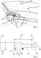
- a vehicle interior 1 which belongs to a vehicle with a tracking system.
- the tracking system includes a steering handle designed as a steering wheel 3 with sensors 5 arranged on both sides for determining a user touch effected by a hand 7, for example.
- the tracking system can be switched on by means of a lever 9 . In other words, switching on means that an automatic steering function is requested; the actual activation of the automatic steering may only take place when other conditions are met.
- the tracking system ie the automatic steering function
- the vehicle automatically follows the course of the road recorded by a camera 11, ie without further steering intervention by the user.
- the camera 11 can no longer reliably determine the course of the lane at a construction site, for example, then the user is asked to take over the task of steering.
- the sensors 5, ie at least one of the sensors 5, recognize that the vehicle user has taken over the task of driving.
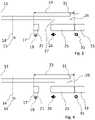
- the 2 shows an embodiment of a functional sequence for activating a tracking system after starting from a rest state 13, ie after a vehicle start from the rest state 13.
- a rest state 13 ie after a vehicle start from the rest state 13.
- all control devices are woken up, ie a computing unit 8 or a control device of the tracking system is started up.
- the start-up takes place by switching on the ignition or an equivalent action.
- the vehicle drives off and shows the symbol 15 at time 14 that the lane guidance system Available.
- the conditions for automatic steering are now met, for example, the camera 11 can recognize the course of the road, the speed is within a predetermined range, etc., so that automatic steering is possible in principle.
- a symbol 19 indicates operational readiness.
- the user is prompted to take hold of the steering wheel 3 in the area of the sensors 5.
- grasping is to be understood as an approach followed by touching the sensor. If the steering wheel is already held in the sensor area and is therefore already touched, then a movement away and a subsequent movement of the hand with a renewed touch of a sensor 5 is necessary.
- time window 23 it is monitored whether such a touch, ie the movement of the hand 7 with subsequent touch, comes about or not.
- the time window 23 defines a period of time starting from the time of operational readiness 17. If after a predetermined time after the time 17 the touch does not occur, after the first graphic display 21 has gone out, a second graphic display 25 accompanied by an acoustic indication 26 is displayed. In this example 2 the user takes his hand away from the sensor area, whereupon the sensor 5 emits the signal 27 beginning with a negative edge. Sensor 5 is only touched after the hand has approached the steering wheel outside of time window 23. Outside of time window 23, sensor 5 sends a signal with a positive edge 29 and a trigger signal 31 is sent to computing unit 8 of the tracking system.
- the length of time from the occurrence of operational readiness 17 to the occurrence of the sensor signal 29 or the trigger signal 31 is determined and compared with the time window 23 . Since the period of time is greater than the time window 23, activation of the tracking system is blocked until the next idle state, ie the tracking system remains deactivated even if the conditions for automatic steering are met and the user requests the system function. The user is informed by a message 33 that the lane guidance system has been activated.
- the sensor 5 sends a signal with a positive edge 29 and a trigger signal 31 is sent to the processing unit 8 of the tracking system within the time window 23, whereupon the tracking system is activated.
- the user is informed with a message 33 about the activated tracking system.
- the symbol 35 indicates to the user that the lane guidance system steers automatically.
- touching of the sensor 5 takes place after the hand has approached the steering wheel within the time window 23 without first removing the hand from the sensor 5 .
- This case occurs, for example, when the user first holds the steering wheel 3 outside the sensor area and touches a sensor 5 in the time window 23 .
- the sensor 5 sends a signal with a positive edge 29 and a trigger signal 31 is sent within the time window 23 to the arithmetic unit 8 of the tracking system, whereupon the tracking system analogously to the description 3 is activated.
- the sensor 5 in the foregoing examples only detects a signal peak caused by a change such as a touch or a touch cessation.
- the sensor 5 can detect at any point in time whether or not there is a hand contact signal. For example, if the hand is already in contact with a sensor 5 before the point in time 17 , the user does not have to lift an adjacent hand in the time window 23 and put it back on again in order to confirm the function of the sensor 5 .
- step S100 starts in step S100 with a start of the tracking system, which is associated with a change in the vehicle state from an idle state to a ready-to-drive state.
- Ready to drive means that the driver only has to engage a gear and/or step on the gas pedal to drive.
- step S102 it is recognized that all boundary conditions for automatic steering are met with the exception of a user request.
- step S103 it is recognized that the user has requested a function of the tracking system, the tracking system is therefore ready for operation. With reaching the Ready for operation, the vehicle user is prompted to touch the steering handle 3 in the area of the sensors. In step S104, it is monitored whether or not a signal caused by touching the sensors occurs within the time window 23 from the point in time at which the system is ready for operation.
- step S106 If no sensor signal occurs, then the function of the tracking system is blocked until a new start according to S100 after an idle state in step S106 and the user is informed. In this case, it is assumed that the sensor 5 or the components connected to the sensor for transmission to the processing unit 8 of the tracking system are defective.
- step S104 If a sensor signal is detected in step S104, then the tracking system is activated in step S108.
- step S110 the user is prompted to take control of the vehicle.
- the takeover is again to be confirmed by detecting the touching of one of the sensors 5 on the steering wheel 3 .
- step S110 If a check in step S110 shows that there was no contact within a further time window after the takeover request, an emergency stop of the vehicle is initiated in step S112 or a corresponding warning message is output. Since the function of the sensor is confirmed in step S104, for example, if there is no sensor signal in step S110, the only cause can be an inability of the user to take over the vehicle. If contact is detected in the further time window, the user can continue to drive the vehicle according to step S114 manually or with the support of the lane guidance system, depending on the operating state.
Landscapes
- Engineering & Computer Science (AREA)
- Transportation (AREA)
- Mechanical Engineering (AREA)
- Automation & Control Theory (AREA)
- Human Computer Interaction (AREA)
- Chemical & Material Sciences (AREA)
- Combustion & Propulsion (AREA)
- Traffic Control Systems (AREA)
- Steering Controls (AREA)
- Control Of Driving Devices And Active Controlling Of Vehicle (AREA)
Description
- Die vorliegende Erfindung betrifft ein Verfahren zum Betrieb eines Spurführungssystems und ein zugehöriges Spurführungssystem eines Fahrzeugs.
- Moderne Kraftfahrzeuge verfügen über Spurführungssystem die zum selbstständigen Lenken eines Fahrzeugs eingerichtet sind, wobei in vielen Fahrsituation die Bereitschaft eines Nutzers zur Übernahme der Fahrzeugsteuerung an einer Lenkhandhabe erforderlich ist. Ist bei einem aktiven Spurführungssystem eine Nutzerberührung der Lenkhandhabe innerhalb einem vorgegebenen Zeitfenster nicht detektierbar, dann wird das Spurführungssystem deaktiviert und bei Berührung wieder aktiviert.
- Aus der
US 2010/0185341 A1 ist bekannt, mit einem im Lenkrad angeordneten Sensor eine Bereitschaft eines Nutzers am Lenkrad durch Detektion einer Berührung zu ermitteln. - Die
DE 10 2010 022 433 A1 offenbart ein Verfahren, bei dem ein Hinweis eine Steuerung des Fahrzeugs zu übernehmen an einen Fahrer ausgegeben wird. Für den Fall, dass keine Fahrerübernahme erkannt wird, erfolgt eine Abschaltung des automatischen arbeitenden Assistenzsystems bei gleichzeitiger Aktivierung der Warnblinkanlage. - Die
US 9 475 521 B1 - Die
DE 10 2013 009423 A1 offenbart ein Verfahren zum Betrieb eines Fahrzeugspurführungssystems mit einer Lenkhandhabe umfassend einen berührungssensitiven Sensor, mittels dem eine Hands-Off Situation des Fahrers erkennbar ist. Im Fall einer Hand-Off-Erkennung wird nach einer vorgegebenen Zeit eine Warnung ausgegeben und gegebenenfalls eine Warnungseskalation eingeleitet, falls keine Reaktion auf die Warnung erfolgt. - Ist ein Sensor defekt liefert dieser kein Sensorsignal und das Ausbleiben des Sensorsignals wird als fehlende Bereitschaft des Fahrzeugnutzers zur Fahrzeugsteuerung interpretiert.
- Es ist demgemäß die Aufgabe der vorliegenden Erfindung ein Verfahren zum Betrieb eines Spurführungssystems und ein Spurführungssystem zur Verfügung zu stellen, welche einen sichereren Betrieb des Spurführungssystems ermöglichen.
- Die Aufgabe wird durch ein Verfahren zum Betrieb eines Spurführungssystems mit den Merkmalen des Anspruchs 1 sowie einem Spurführungssystem gemäß Anspruch 8 gelöst.
- Weitere vorteilhafte Ausgestaltungen der vorliegenden Erfindung sind Gegenstand der abhängigen Ansprüche.
- Bei dem erfindungsgemäßen Verfahren zum Betrieb eines Spurführungssystems mit einer Lenkhandhabe umfassend einen berührungssensitiven Sensor werden folgende Schritte ausgeführt:
- Bestimmung einer Zeitdauer vom Zeitpunkt einer Aufforderung des Spurführungssystems an einen Fahrzeugnutzer zur Berührung der Lenkhandhabe bis zum Auftreten eines durch eine Berührung der Lenkhandhabe im Sensorbereich bewirkten Sensorsignals und Vergleich mit einem vorgegebenen Zeitfenster,
- Sperrung einer Aktivierungsmöglichkeit des Spurführungssystems für den Fall, dass die bestimmte Zeitdauer größer als das vorgegebenen Zeitfenster ist,
- Das Spurführungssystem ist eingerichtet selbstständig zu lenken, hierfür umfasst das Spurführungssystem gemäß dem Stand der Technik beispielsweise Umfeldsensoren wie Kamera, Radar, Lidar zur Erfassung der Umgebung und des Straßenverlaufs, eine Recheneinheit zur Datenauswertung und Aktoren zur Ansteuerung des Lenksystems. Bevorzugt ist das Spurführungssystem mit einem Längsregelsystem gekoppelt, so dass ein autonomer oder teilautonomer Fahrbetrieb realisiert werden kann. Je nach Automatisierungsstufe des Fahrbetriebs muss beispielsweise nach einer vorbestimmten Zeitdauer oder vor bzw. mit Erreichen einer Systemgrenze der Nutzer insbesondere die Lenkaufgabe beziehungsweise die Fahraufgabe umfassend Längs- und Querregelung übernehmen. Die Systemgrenze gibt vor, bis wann autonom oder teilautonom gefahren werden kann. Beispielsweise bei fehlenden Linien zur Kennzeichnung des Straßenrandes, bei starken Niederschlägen oder bei komplexer Verkehrsführung in Baustellenbereichen ist ein autonomes oder teilautonomes Fahren nicht mehr möglich.
- Mit Ergreifen der Lenkhandhabe erkennt ein Sensor, dass der Nutzer das Lenken des Fahrzeugs übernimmt. Wird erkannt, dass der Fahrer die Lenkaufgabe nicht übernimmt, muss von gesundheitlicher Beeinträchtigung des Fahrers ausgegangen und bevorzugt ein Nothalt des Fahrzeugs eingeleitet werden. Ist der Sensor defekt oder fährt der Nutzer mit Handschuhen, kann in einer Übernahmesituation aus einem autonomen Fahrbetrieb ein Ergreifen der Lenkhandhabe durch den Nutzer nicht erkannt werden, so dass ungewollt der Nothalt ausgeführt werden würde. Unter dem Begriff Sensor sind im Sinne der Anmeldung neben dem Sensor selbst die zugehörigen Komponenten zur Übermittlung und Auswertung eines Sensorsignals, d.h. die Verkabelung, die Auswerteeinheit etc. zu verstehen. Das erfindungsgemäße Verfahren vermeidet diesen für diese Situation überflüssigen Nothalt, indem unmittelbar nach einem Ruhezustand des Fahrzeugs eine Initialisierung, d.h. eine Überprüfung der Funktionsfähigkeit des Sensors durchgeführt und erst nach bestätigter Funktionsfähigkeit des Sensors das Spurführungssystem aktivierbar ist. Gleichzeitig wird eine korrekt arbeitende Sensoreinheit zur Erfassung der Berührung durch den Fahrer gewährleistet.
- Eine Betriebsbereitschaft des Spurführungssystems ist im Sinne der vorliegenden Anmeldung beispielsweise gegeben, sobald der Nutzer das Spurführungssystem durch Einschalten angefordert hat und alle Bedingungen für die Funktion des Spurführungssystems erfüllt sind, die Betriebsbereitschaft wird durch ein Symbol wie beispielsweise ein Lenkrad-Icon angezeigt. Die Bedingungen für eine Funktion des Spurführungssystems setzen beispielsweise voraus, dass die Umfeldsensorik zuverlässig Straßenbegrenzungen erfasst, das Fahrzeug in einem zulässigen Geschwindigkeitsbereich fährt oder die Lenkaktoren funktionsfähig sind.
- Für den Fall, dass die bestimmte Zeitdauer ab dem Zeitpunkt der Aufforderung an einen Fahrzeugnutzer zur Berührung der Lenkhandhabe bis zur Erkennung des durch die Berührung bewirkten Sensorsignals größer als das vorgegebene Zeitfenster ist, erfolgt keine Aktivierungsmöglichkeit des Spurführungssystems bis zum nächsten Ruhezustand bzw. bis zu einem Wecken aus dem Ruhezustand. Der Ruhezustand des Spurhaltesystems geht mit einem Ruhezustand des Fahrzeugs einher, bei Verbrennungsfahrzeugen wird der Ruhezustand durch Beendigung eines Zündungslaufs erreicht, d.h. der Ruhezustand ist nach Abschalten von Klemme 15 bevorzugt inklusive Nachlauf erreicht. Bei Elektrofahrzeugen wäre der Ruhezustand beispielsweise charakterisiert durch Abschaltung bzw. durch in einen Schlafmodus versetzte Steuergeräte von zumindest der Antriebseinrichtung und/oder des Bordnetzes analog Abschaltung von Klemme 15. Das Spurführungssystem bleibt abgeschaltet bzw. eine Aktivierungsmöglichkeit ist gesperrt bis zum nächsten Ruhezustand und ist bis dahin nicht mehr verfügbar, der Nutzer erhält eine Information über ein Systemdefekt. Durch das Verfahren wird in vorteilhafter Weise vermieden, dass bei Erreichen der Betriebsbereitschaft, d.h. das Spurführungssystem ist vom Nutzer angefordert und Bedingungen zum Betrieb sind erfüllt, bei Ausbleiben eines Sensorsignals, beispielsweise aufgrund eines Defekts, ein Nothalt eingeleitet und eine damit verbundene Verunsicherung des Nutzers ausgelöst wird.
- Gemäß einer Ausführungsform erfolgt für den Fall, dass die bestimmte Zeitdauer ab dem Zeitpunkt der Aufforderung an einen Fahrzeugnutzer zur Berührung der Lenkhandhabe bis zur Erkennung des durch die Berührung bewirkten Sensorsignals kleiner als das vorgegebene Zeitfenster ist, d.h. das Auftreten des Sensorsignals innerhalb dem vorgegebenen Zeitfenster detektiert wird, eine Freigabe einer Aktivierung des Spurführungssystems. Mit anderen Worten ist in dem Fall die Initialisierung der Sensoren erfolgreich. Mit der erfolgreichen Initialisierung wird das Spurführungssystem aktiviert sobald Betriebsbereitschaft gegeben ist. Das aktivierte Spurführungssystem lenkt selbstständig, die Funktion wird beispielsweise durch ein grünes Lenkradicon dargestellt. Ist die Aktivierung des Spurführungssystems einmal freigegeben, dann ist die Funktion der Sensoren nachgewiesen und das Spurführungssystem kann damit nach einer Deaktivierung jederzeit wieder aktiviert werden. Wird das Spurführungssystem beispielsweise aufgrund nicht erfüllter Bedingungen deaktiviert, so ist dieses jederzeit aktivierbar, sobald die Bedingungen wieder erfüllt sind. Wird das Spurführungssystem beispielsweise aufgrund fehlender Fahrbahnmarkierungen deaktiviert, kann ein Nutzer durch Anforderung das Spurführungssystem wieder aktivieren, sobald die Fahrbahnmarkierungen wieder vorhanden sind.
- Gemäß einer weiteren Ausführungsform der Erfindung erfolgt die Aufforderung zur Berührung der Lenkhandhabe mit Eintreten einer Betriebsbereitschaft des Spurführungssystems. Sobald das Spurführungssystem betriebsbereit ist, d.h. alle Bedingungen für die Funktion des Spurführungssystems sind erfüllt und der Nutzer hat die Systemfunktion angefordert, erfolgt die Aufforderung zur Berührung der Lenkhandhabe. Die Initialisierung erfolgt damit, sobald der Nutzer nach einem Ruhezustand des Fahrzeugs erstmalig mit Unterstützung des Spurführungssystems fahren will. In vorteilhafter Weise erfolgt die Überprüfung der Sensoren nur, wenn der Nutzer die Unterstützung des Spurführungssystems anfordert.
- Gemäß einer Ausgestaltung der vorliegenden Erfindung wird ein Fahrzeugnutzer optisch, akustisch und/oder haptisch aufgefordert die Lenkhandhabe im Sensorbereich zu berühren. Mit anderen Worten wird der Nutzer aufgefordert, nach jedem Ruhezustand des Fahrzeugs eine Prüfung der Sensorfunktion zu bewirken, wodurch überflüssige Nothaltmanöver vermieden sind.
- Gemäß einer weiteren Ausgestaltung der vorliegenden Erfindung wird mit Ausbleiben einer Berührung nach einer vorgegebenen Zeitdauer nach einer Aufforderung zur Berührung der Lenkhandhabe der Fahrzeugnutzer erneut optisch, akustisch und/oder haptisch bevorzugt mit einer erhöhten Intensität aufgefordert die Lenkhandhabe im Sensorbereich zu berühren. Die erneute Aufforderung vor Sperrung der Aktivierungsmöglichkeit lenkt verstärkt die Aufmerksamkeit des Nutzers auf die Anzeige und bewegt den Nutzer zur Berührung des Sensors, so dass die Zeitdauer vom Zeitpunkt einer Aufforderung des Spurführungssystems bis zum Auftreten eines durch eine Berührung der Lenkhandhabe im Sensorbereich bewirkten Sensorsignals kleiner als das vorgegeben Zeitfenster ist.
- Gemäß einer weiteren Ausgestaltung umfasst die Berührung der Lenkhandhabe eine Annäherung eines Bedienelements und folgende Berührung des Lenkrads. Gemäß dieser Ausgestaltung wird nur ein Sensorsignal als gültig erkannt, das durch ein Berühren eines vorher nicht berührten Sensors bewirkt wird. Als Betätigung wird nur ein durch eine annähernde Hand mit folgender Berührung bewirktes Signal als gültiges Signal erkannt, beispielsweise ein mit positiver Flanke beginnendes Sensorsignal. In vorteilhafter Weise wird verhindert, dass ein durch Entfernung einer Hand vom Lenkrad bewirktes Sensorsignal zur Aktivierung des Spurführungssystems führt.
- Gemäß einer weiteren Ausgestaltung der vorliegenden Erfindung wird der Fahrzeugnutzer über die Sperrung der Aktivierungsmöglichkeit des Spurführungssystems bis zum folgenden Ruhezustand mittels einer optisch, akustisch und/oder haptischen Anzeige informiert, bevorzugt wird der Nutzer über einen möglichen technischen Defekt des Sensors informiert.
- Die erfindungsgemäße Vorrichtung umfasst ein Spurführungssystem mit einem an einer Lenkhandhabe angeordneten berührungssensitiven Sensor,
- einer Recheneinheit, die eine Zeitdauer von einer Aufforderung des Spurführungssystems an einen Fahrzeugnutzer zur Berührung der Lenkhandhabe bis zum Auftreten des durch eine Berührung bewirkten Sensorsignals ermittelt und mit einem vorgegebenen Zeitfenster vergleicht, wobei
- die Recheneinheit eine Aktivierungsmöglichkeit des Spurführungssystems sperrt für den Fall, dass die bestimmt Zeitdauer größer als das vorgegebene Zeitfenster ist, wobei die Aktivierungsmöglichkeit des Spurführungssystems bei einer erstmaligen Aufforderung zur Berührung der Lenkhandhabe nach einem Ruhezustand bis zu einem nachfolgenden Ruhezustand des Fahrzeugs gesperrt bleibt. In vorteilhafter Weise vermeidet das Spurführungssystem, dass bei Ausbleiben eines Sensorsignals nach Aufforderung an einen Nutzer, beispielsweise aufgrund eines Sensordefekts oder einer Bedienung mit Handschuhen, die Einleitung eines Nothaltemanövers vermieden ist.
- Gemäß einer weiteren Ausgestaltung der vorliegenden Erfindung ist der Sensor als ein kapazitiver, induktiver, resistiver oder als optischer Sensor ausgeführt ist. Die Sensoren ermöglichen eine zuverlässige Erkennung einer Berührung durch eine Hand.
- Die vorliegende Erfindung wird nachstehend anhand von Ausführungsbeispielen unter Bezugnahme auf die beiliegende Zeichnung näher erläutert, in der gleiche oder ähnliche Teile mit gleichen Bezugszeichen bezeichnet sind.
- Es zeigt:
-
Fig. 1 eine schematische Ansicht eines Fahrzeuginnenraums; -
Fig. 2 eine Darstellung eines Funktionsablaufs des erfindungsgemäßen Verfahrens; -
Fig. 3 eine weitere Darstellung eines Funktionsablaufs des erfindungsgemäßen Verfahrens; -
Fig. 4 eine weitere Darstellung eines Funktionsablaufs des erfindungsgemäßen Verfahrens und -
Fig. 5 ein Ablaufdiagramm des erfindungsgemäßen Verfahrens. - Bevor detailliert die Ausführungsbeispiele der vorliegenden Erfindung beschrieben werden, wird ein in allen nachstehend erläuterten Ausführungsbeispielen der vorliegenden Erfindung verwendeter Aufbau beschrieben.
- In
Fig. 1 ist ein Fahrzeuginnenraum 1 gezeigt, der einem Fahrzeug mit einem Spurführungssystem zugehörig ist. Das Spurführungssystem umfasst ein als Lenkrad 3 ausgeführte Lenkhandhabe mit beidseitig angeordneten Sensoren 5 zur Bestimmung einer von beispielsweise einer Hand 7 bewirkten Nutzerberührung. Mittels einem Hebel 9 ist das Spurführungssystem einschaltbar. Einschalten bedeutet mit anderen Worten, dass eine automatische Lenkfunktion angefordert wird, die eigentliche Aktivierung des automatischen Lenkens erfolgt gegebenenfalls erst mit Erfüllung weiterer Bedingungen. Sobald das Spurführungssystem, d.h. die automatische Lenkfunktion aktiviert ist folgt das Fahrzeug automatisiert, d.h. ohne weitere Lenkeingriffe des Nutzers dem mit einer Kamera 11 erfassten Straßenverlauf. Kann die Kamera 11 den Fahrspurverlauf beispielsweise in einer Baustelle nicht mehr zuverlässig bestimmen, dann wird der Nutzer aufgefordert die Lenkaufgabe zu übernehmen. Mit Ergreifen des Lenkrads 3 durch die Hand 7 erkennen die Sensoren 5, d.h. zumindest einer der Sensoren 5, die Übernahme der Fahraufgabe durch den Fahrzeugnutzer. - Die
Fig. 2 zeigt eine Ausführungsform eines Funktionsablaufs zur Aktivierung eines Spurführungssystems nach einem Start aus einem Ruhezustand 13, d.h. nach einem Fahrzeugstart aus dem Ruhezustand 13. Mit Inbetriebnahme des Fahrzeugs werden alle Steuergeräte geweckt, d.h. eine Recheneinheit 8 bzw. ein Steuergerät des Spurführungssystems wird hochgefahren. Die Inbetriebnahme erfolgt durch Einschalten der Zündung oder eine äquivalenten Handlung. Nach dem Start fährt das Fahrzeug los und zeigt mit dem Symbol 15 zum Zeitpunkt 14 an, dass das Spurführungssystem zur Verfügung steht. Die Bedingungen zum automatischen Lenken sind nun erfüllt, beispielsweise kann die Kamera 11 den Straßenlauf erkennen, die Geschwindigkeit liegt in einem vorgegebenen Bereich etc., so dass ein automatisches Lenken prinzipiell möglich ist. - Zum Zeitpunkt 17 sind die Bedingungen zum automatischen Lenken weiterhin erfüllt, desweiteren hat jetzt der Nutzer das Spurführungssystem eingeschaltet bzw. angefordert, ein Symbol 19 zeigt die Betriebsbereitschaft an. Mit einer ersten graphischen Anzeige 21 wird der Nutzer aufgefordert, das Lenkrad 3 im Bereich der Sensoren 5 zu ergreifen. Bei den Sensoren 5, die durch einen Signalpeak lediglich eine Zustandsänderung detektierten, ist mit Ergreifen eine Annäherung mit anschließender Sensorberührung zu verstehen. Wenn das Lenkrad bereits im Sensorbereich gehalten wird und damit schon berührt ist, dann ist eine Wegbewegung und eine anschließende Zubewegung der Hand mit einer erneuten Berührung eines Sensors 5 erforderlich.
- Im Zeitfenster 23 wird überwacht, ob eine derartige Berührung, d.h. die Zubewegung der Hand 7 mit anschließender Berührung zustande kommt oder nicht. Das Zeitfenster 23 definiert eine Zeitdauer beginnend vom Zeitpunkt der Betriebsbereitschaft 17.Tritt nach einer vorgegebenen Zeit nach dem Zeitpunkt 17 die Berührung nicht auf wird nach Erlöschen der ersten graphischen Anzeige 21 eine zweite graphische Anzeige 25 begleitet von einem akustischen Hinweis 26 angezeigt. In vorliegendem Beispiel nach
Fig. 2 nimmt der Nutzer die Hand vom Sensorbereich weg, worauf der Sensor 5 das mit einer negativen Flanke beginnende Signal 27 aussendet. Eine Berührung des Sensors 5 nach Annäherung der Hand an das Lenkrad erfolgt erst außerhalb des Zeitfensters 23. Außerhalb des Zeitfensters 23 sendet der Sensor 5 ein Signal mit positiver Flanke 29 und ein Tiggersignal 31 wird an die Recheneinheit 8 des Spurführungssystems geschickt. Die Zeitdauer vom Auftreten der Betriebsbereitschaft 17 bis zum Auftreten des Sensorsignals 29 bzw. des Triggersignals 31 wird ermittelt und mit dem Zeitfenster 23 verglichen. Da die Zeitdauer größer als das Zeitfenster 23 ist wird eine Aktivierung des Spurführungssystems bis zum nächsten Ruhezustand gesperrt, d.h. das Spurführungssystem bleibt deaktivert selbst wenn die Bedingungen zum automatischen Lenken erfüllt sind und der Nutzer die Systemfunktion anfordert. Der Nutzer wird mit einer Meldung 33 über die gesperrte Aktivierung des Spurführungssystems informiert. - Im Anwendungsfall nach
Fig. 3 erfolgt im Unterschied zurFig. 2 eine Berührung des Sensors 5 nach Annäherung der Hand an das Lenkrad innerhalb des Zeitfensters 23, der Sensor 5 sendet ein Signal mit positiver Flanke 29 und ein Tiggersignal 31 wird innerhalb des Zeitfensters 23 an die Recheneinheit 8 des Spurführungssystems geschickt, worauf das Spurführungssystem aktiviert wird. Der Nutzer wird mit einer Meldung 33 über das aktivierte Spurführungssystem informiert. Das Symbol 35 zeigt dem Nutzer an, dass das Spurführungssystem automatisch lenkt. - In einem weiteren Anwendungsfall nach
Fig. 4 erfolgt eine Berührung des Sensors 5 nach Annäherung der Hand an das Lenkrad innerhalb des Zeitfensters 23 ohne vorher die Hand vom Sensor 5 wegzunehmen. Dieser Fall tritt beispielsweise auf, wenn der Nutzer das Lenkrad 3 zuerst außerhalb des Sensorbereichs hält und im Zeitfenster 23 ein Sensor 5 berührt. Der Sensor 5 sendet ein Signal mit positiver Flanke 29 und ein Tiggersignal 31 wird innerhalb des Zeitfensters 23 an die Recheneinheit 8 des Spurführungssystems geschickt, worauf das Spurführungssystem analog der Beschreibung zuFig. 3 aktiviert wird. - Der Sensor 5 erkennt in den vorangehenden Beispielen nur einen Signalpeak bewirkt durch eine Änderung wie eine Berührung oder Beendigung einer Berührung.
- In einer weiteren nicht dargestellten Ausführungsform kann der Sensor 5 zu jedem Zeitpunkt erkennen, ob ein Handanliegesignal vorliegt oder nicht. Liegt die Hand beispielsweise bereits vor dem Zeitpunkt 17 an einem Sensor 5 an, muss der Nutzer im Zeitfenster 23 eine anliegende Hand nicht abheben und wieder auflegen, um die Funktion des Sensors 5 zu bestätigen.
- Das in
Fig. 5 gezeigte Ablaufverfahren startet im Schritt S100 mit einem Start des Spurführungssystems, das mit einer Änderung des Fahrzeugzustands von einem Ruhezustand in einen fahrbereiten Zustand verbunden ist. Fahrbereit bedeutet, der Fahrer muss zum Fahren lediglich einen Gang einlegen und/oder das Gaspedal treten. - Im Schritt S102 wird erkannt, dass alle Randbedingungen zum automatischen Lenken mit Ausnahme einer Nutzeranforderung erfüllt sind.
- Im Schritt S103 wird erkannt, dass der Nutzer eine Funktion des Spurführungssystems angefordert hat, das Spurführungssystem ist damit betriebsbereit. Mit Erreichen der Betriebsbereitschaft ergeht eine Aufforderung an den Fahrzeugnutzer, die Lenkhandhabe 3 im Bereich der Sensoren zu berühren. Im Schritt S104 wird überwacht, ob ab dem Zeitpunkt der Betriebsbereitschaft Aufforderung ein durch die Berührung der Sensoren bewirktes Signal innerhalb des Zeitfensters 23 auftritt oder nicht.
- Tritt kein Sensorsignal auf, dann wird die Funktion des Spurführungssystems bis zu einem neuen Start gemäß S100 nach einem Ruhezustand im Schritt S106 gesperrt und der Nutzer informiert. In dem Fall wird davon ausgegangen, dass der Sensor 5 oder die mit dem Sensor verbunden Bauteile zur Übermittlung an die Recheneinheit 8 des Spurführungssystems defekt sind.
- Wird ein Sensorsignal im Schritt S104 detektiert, dann wird das Spurführungssystem im Schritt S 108 aktiviert.
- Sofern die Randbedingungen zum automatischen Lenken im Schritt S110 nicht mehr erfüllt sind, wird der Nutzer aufgefordert die Fahrzeugführung zu übernehmen. Die Übernahme ist wiederum durch Detektion der Berührung eines der Sensoren 5 am Lenkrad 3 zu bestätigen.
- Ergibt eine Überprüfung im Schritt S110, dass innerhalb einem weiteren Zeitfensters nach der Übernahmeaufforderung keine Berührung erfolgt ist, so wird im Schritt S112 ein Nothalt des Fahrzeugs eingeleitet oder eine entsprechende Warnmeldung ausgegeben. Da im Schritt S104 beispielsweise die Funktion des Sensors bestätigt wird, kann bei Ausbleiben des Sensorsignals im Schritt S110 nur ein Unvermögen des Nutzers zur Fahrzeugübernahme ursächlich sein. Wird in dem weiteren Zeitfenster eine Berührung erkannt, kann der Nutzer je nach Betriebszustand das Fahrzeug gemäß Schritt S114 manuell oder mit Unterstützung des Spurführungssystems weiterfahren.
Claims (9)
- Verfahren zum Betrieb eines Fahrzeugspurführungssystems mit einer Lenkhandhabe umfassend einen berührungssensitiven Sensor mit folgenden Schritten:- Bestimmung einer Zeitdauer vom Zeitpunkt einer Aufforderung des Spurführungssystems an einen Fahrzeugnutzer zur Berührung der Lenkhandhabe bis zum Auftreten eines durch eine Berührung der Lenkhandhabe im Sensorbereich bewirkten Sensorsignals und Vergleich mit einem vorgegebenen Zeitfenster (S104), gekennzeichnet durch,- Sperrung einer Aktivierungsmöglichkeit des Spurführungssystems bei einer erstmaligen Aufforderung zur Berührung der Lenkhandhabe nach einem Ruhezustand für den Fall, dass die bestimmte Zeitdauer größer als das vorgegebenen Zeitfenster ist (S106),wobei die Aktivierungsmöglichkeit bis zu einem folgenden Ruhezustand gesperrt wird und das Spurführungssystem bis zu dem folgenden Ruhezustand nicht mehr zur Verfügung steht.
- Verfahren nach Anspruch 1,
dadurch gekennzeichnet, dass
eine Freigabe der Aktivierungsmöglichkeit des Spurführungssystems erfolgt für den Fall, dass die bestimmte Zeitdauer kleiner als das vorgegebene Zeitfenster ist (S108). - Verfahren nach Anspruch 1 oder 2,
dadurch gekennzeichnet, dass
die Aufforderung zur Berührung der Lenkhandhabe mit Eintreten einer Betriebsbereitschaft des Spurführungssystems erfolgt. - Verfahren nach einem der Ansprüche 1 bis 3,
dadurch gekennzeichnet, dass
der Nutzer optisch, akustisch und/oder haptisch aufgefordert wird die Lenkhandhabe im Sensorbereich zu berühren. - Verfahren nach Anspruch 4,
dadurch gekennzeichnet, dass
mit Ausbleiben einer Berührung nach einer vorgegebenen Zeitdauer nach Aufforderung des Fahrzeugnutzers erneut optisch und/oder akustisch aufgefordert wird die Lenkhandhabe im Sensorbereich zu berühren. - Verfahren nach einem der Ansprüche 1 bis 5,
dadurch gekennzeichnet, dass
die Berührung der Lenkhandhabe eine Annäherung eines Bedienelements und eine darauffolgende Berührung des Lenkrads beinhaltet. - Verfahren nach einem der Ansprüche 1 bis 6,
dadurch gekennzeichnet, dass
der Fahrzeugnutzer über die Sperrung der Aktivierungsmöglichkeit des Spurführungssystems bis zum folgenden Ruhezustand mittels einer grafischen und/oder akustischen Anzeige informiert wird. - Spurführungssystem zur Durchführung des Verfahrens nach den Ansprüchen 1 bis 7, miteinem an einer Lenkhandhabe (3) angeordneten berührungssensitiven Sensor (5), einer Recheneinheit (8), die eine Zeitdauer von einer Aufforderung des Spurführungssystems an einen Fahrzeugnutzer zur Berührung der Lenkhandhabe bis zum Auftreten des durch eine Berührung bewirkten Sensorsignals (29) ermittelt und mit einem vorgegebenen Zeitfenster (23) vergleicht,dadurch gekennzeichnet, dassdie Recheneinheit (8) die Aktivierungsmöglichkeit des Spurführungssystems bei einer erstmaligen Aufforderung zur Berührung der Lenkhandhabe (3) nach einem Ruhezustand sperrt für den Fall, dass die bestimmte Zeitdauer größer als das vorgegebene Zeitfenster (23) ist, wobei die Aktivierungsmöglichkeit bis zu einem folgenden Ruhezustand gesperrt bleibt.
- Spurführungssystem nach Anspruch 8,
dadurch gekennzeichnet, dass
der Sensor als ein kapazitiver, induktiver, resistiver oder als optischer Sensor ausgeführt ist.
Applications Claiming Priority (2)
| Application Number | Priority Date | Filing Date | Title |
|---|---|---|---|
| DE102019000461.2A DE102019000461B4 (de) | 2019-01-22 | 2019-01-22 | Verfahren zum Betrieb eines Spurführungssystems und Spurführungssystem |
| PCT/EP2020/051068 WO2020152030A1 (de) | 2019-01-22 | 2020-01-16 | Verfahren zum betrieb eines spurführungssystems und spurführungssystem |
Publications (2)
| Publication Number | Publication Date |
|---|---|
| EP3914494A1 EP3914494A1 (de) | 2021-12-01 |
| EP3914494B1 true EP3914494B1 (de) | 2022-09-28 |
Family
ID=69192031
Family Applications (1)
| Application Number | Title | Priority Date | Filing Date |
|---|---|---|---|
| EP20701928.2A Active EP3914494B1 (de) | 2019-01-22 | 2020-01-16 | Verfahren zum betrieb eines spurführungssystems und spurführungssystem |
Country Status (5)
| Country | Link |
|---|---|
| US (1) | US11945501B2 (de) |
| EP (1) | EP3914494B1 (de) |
| CN (1) | CN113329926B (de) |
| DE (1) | DE102019000461B4 (de) |
| WO (1) | WO2020152030A1 (de) |
Families Citing this family (2)
| Publication number | Priority date | Publication date | Assignee | Title |
|---|---|---|---|---|
| JP7663315B2 (ja) * | 2019-07-05 | 2025-04-16 | 株式会社Subaru | 車両の操舵支援装置 |
| US12555385B2 (en) * | 2021-12-02 | 2026-02-17 | Nvidia Corporation | Deep learning based operational domain verification using camera-based inputs for autonomous systems and applications |
Family Cites Families (15)
| Publication number | Priority date | Publication date | Assignee | Title |
|---|---|---|---|---|
| US20100185341A1 (en) | 2009-01-16 | 2010-07-22 | Gm Global Technology Operations, Inc. | Vehicle mode activation by gesture recognition |
| DE102010022433A1 (de) * | 2010-06-02 | 2011-12-08 | Audi Ag | Verfahren zur Steuerung des Betriebs eines vollautomatischen, zur unabhängigen Fahrzeugführung ausgebildeten Fahrerassistenzsystems eines Kraftfahrzeugs und Kraftzeug |
| DE112012006826T5 (de) * | 2012-12-28 | 2015-05-21 | Toyota Jidosha Kabushiki Kaisha | Fahrzeugsteuerungsgerät |
| US9475521B1 (en) * | 2015-06-08 | 2016-10-25 | Honda Motor Co., Ltd. | Failsafe detection |
| DE102013009423A1 (de) * | 2013-06-04 | 2014-12-04 | Volkswagen Aktiengesellschaft | Notfallassistenz mit aktivierter Querführungsunterstützung |
| JP6156077B2 (ja) * | 2013-11-08 | 2017-07-05 | トヨタ自動車株式会社 | 車両制御装置 |
| JP6141759B2 (ja) * | 2013-12-18 | 2017-06-07 | 本田技研工業株式会社 | 車両制御装置 |
| CN103978977B (zh) * | 2014-04-28 | 2016-09-07 | 中国科学院深圳先进技术研究院 | 基于人体通信的汽车监控系统和方法 |
| CN110871809A (zh) * | 2014-06-23 | 2020-03-10 | 本田技研工业株式会社 | 控制机动车辆中的车辆系统的方法 |
| DE102015207025A1 (de) * | 2015-04-17 | 2016-10-20 | Bayerische Motoren Werke Aktiengesellschaft | Fahrerassistenzsystem in einem Kraftfahrzeug |
| JP6264351B2 (ja) * | 2015-09-28 | 2018-01-24 | トヨタ自動車株式会社 | 車両の運転支援装置 |
| JP6661225B2 (ja) * | 2016-03-29 | 2020-03-11 | 本田技研工業株式会社 | 制御支援車両 |
| US11001271B2 (en) * | 2016-07-12 | 2021-05-11 | Honda Motor Co., Ltd. | Drive assistance device |
| CN106274483A (zh) * | 2016-11-10 | 2017-01-04 | 合肥工业大学 | 基于分心驾驶行为判别的车辆自动驾驶切换装置及方法 |
| JP6673299B2 (ja) | 2017-06-06 | 2020-03-25 | トヨタ自動車株式会社 | 操舵支援装置 |
-
2019
- 2019-01-22 DE DE102019000461.2A patent/DE102019000461B4/de active Active
-
2020
- 2020-01-16 EP EP20701928.2A patent/EP3914494B1/de active Active
- 2020-01-16 CN CN202080009767.4A patent/CN113329926B/zh active Active
- 2020-01-16 WO PCT/EP2020/051068 patent/WO2020152030A1/de not_active Ceased
- 2020-01-16 US US17/424,544 patent/US11945501B2/en active Active
Also Published As
| Publication number | Publication date |
|---|---|
| WO2020152030A1 (de) | 2020-07-30 |
| EP3914494A1 (de) | 2021-12-01 |
| US11945501B2 (en) | 2024-04-02 |
| US20220073138A1 (en) | 2022-03-10 |
| CN113329926A (zh) | 2021-08-31 |
| DE102019000461A1 (de) | 2020-07-23 |
| CN113329926B (zh) | 2024-06-25 |
| DE102019000461B4 (de) | 2023-11-30 |
Similar Documents
| Publication | Publication Date | Title |
|---|---|---|
| EP3390190B1 (de) | Verfahren zum deaktivieren einer automatisierten fahrfunktion eines fahrzeugs und fahrerassistenzsystem zur durchführung des verfahrens | |
| EP2819871B1 (de) | Verfahren zum betrieb eines fahrerassistenzsystems zur autonomen längs- und/oder querregelung eines fahrzeugs und fahrerassistenzsystem, das nach einem derartigen verfahren arbeitet | |
| EP3233603B1 (de) | Fahrerassistenzeinrichtung für einen kraftwagen sowie verfahren zum betreiben einer solchen | |
| EP3003767B1 (de) | Notfallassistenz zur fahrzeugführung | |
| DE102013222048B4 (de) | Verfahren und Vorrichtung zum Aktivieren oder Deaktivieren einer automatischen Fahrfunktion | |
| DE102009010006B4 (de) | Verfahren und Vorrichtung zum teilautonomen oder autonomen Fahren eines Kraftfahrzeugs | |
| WO2013060530A1 (de) | Verfahren und vorrichtung zum betrieb eines stauassistenzsystems eines kraftfahrzeugs | |
| DE102016210452B4 (de) | Verfahren und Vorrichtung für ein Fahrzeug mit Notfallassistenzeinheit | |
| EP3423324B1 (de) | Pedalsystem für ein zum zumindest teilautomatisierten fahren ausgebildetes fahrzeug | |
| DE102018210320A1 (de) | Fahrsystem mit einer per Lenkeingriff deaktivierbaren automatisierten Querführung sowie Verfahren zum Deaktivieren einer automatisierten Querführung | |
| DE102012215057A1 (de) | Fahrerassistenzsystem | |
| DE102017208508A1 (de) | Hands-On-Detektion mit Unterscheidung des Anliegens lediglich einer einzigen Hand und beider Hände am Lenkrad und darauf basierendes Fahrerassistenzsystem | |
| DE102013010928A1 (de) | Verfahren zum Betreiben wenigstens eines Fahrerassistenzsystems eines Kraftwagens und Kraftwagen mit wenigstens einem Fahrerassistenzsystem | |
| WO2017182489A1 (de) | Längsregelsystem für ein kraftfahrzeug | |
| EP4320021B1 (de) | Verfahren zum betrieb eines assistenzsystems sowie assistenzsystem | |
| DE102013225138A1 (de) | Automatische Blinkerassistenz | |
| WO2020002479A1 (de) | Fahrerassistenzsystem, fahrzeug, verfahren zum betreiben des fahrerassistenzsystems, computerprogramm und computerlesbares speichermedium | |
| DE102015015097A1 (de) | Verfahren zum Betrieb eines Fahrzeugs | |
| EP3914494B1 (de) | Verfahren zum betrieb eines spurführungssystems und spurführungssystem | |
| DE102014201544A1 (de) | Längsregelsystem für ein Kraftfahrzeug | |
| DE102018207675A1 (de) | Verfahren zum Umschalten zwischen unterschiedlichen Automatisierungsstufen eines Fahrzeugs | |
| EP4366998B1 (de) | Verfahren zum bestimmen einer hands-off-zeit für ein automatisiertes kraftfahrzeug | |
| DE102013002778A1 (de) | Überwachen einer Reaktionsbereitschaft eines Fahrers eines Kraftfahrzeugs | |
| WO2024022920A1 (de) | Verfahren zum betreiben eines spurführungsassistenten eines fahrzeugs unter berücksichtigung von fahrereingriffen, spurführungsassistent sowie fahrzeug | |
| DE102020120867A1 (de) | Verfahren zum Betreiben eines Fahrassistenzsystems eines Kraftfahrzeugs |
Legal Events
| Date | Code | Title | Description |
|---|---|---|---|
| STAA | Information on the status of an ep patent application or granted ep patent |
Free format text: STATUS: UNKNOWN |
|
| STAA | Information on the status of an ep patent application or granted ep patent |
Free format text: STATUS: THE INTERNATIONAL PUBLICATION HAS BEEN MADE |
|
| PUAI | Public reference made under article 153(3) epc to a published international application that has entered the european phase |
Free format text: ORIGINAL CODE: 0009012 |
|
| STAA | Information on the status of an ep patent application or granted ep patent |
Free format text: STATUS: REQUEST FOR EXAMINATION WAS MADE |
|
| 17P | Request for examination filed |
Effective date: 20210709 |
|
| AK | Designated contracting states |
Kind code of ref document: A1 Designated state(s): AL AT BE BG CH CY CZ DE DK EE ES FI FR GB GR HR HU IE IS IT LI LT LU LV MC MK MT NL NO PL PT RO RS SE SI SK SM TR |
|
| RAP3 | Party data changed (applicant data changed or rights of an application transferred) |
Owner name: MERCEDES-BENZ GROUP AG |
|
| GRAP | Despatch of communication of intention to grant a patent |
Free format text: ORIGINAL CODE: EPIDOSNIGR1 |
|
| STAA | Information on the status of an ep patent application or granted ep patent |
Free format text: STATUS: GRANT OF PATENT IS INTENDED |
|
| RIC1 | Information provided on ipc code assigned before grant |
Ipc: B60W 50/029 20120101ALI20220317BHEP Ipc: B60W 60/00 20200101ALI20220317BHEP Ipc: B60W 50/02 20120101ALI20220317BHEP Ipc: B60W 50/16 20200101ALI20220317BHEP Ipc: B60W 50/14 20200101ALI20220317BHEP Ipc: B60W 30/12 20200101AFI20220317BHEP |
|
| DAV | Request for validation of the european patent (deleted) | ||
| DAX | Request for extension of the european patent (deleted) | ||
| INTG | Intention to grant announced |
Effective date: 20220411 |
|
| GRAS | Grant fee paid |
Free format text: ORIGINAL CODE: EPIDOSNIGR3 |
|
| GRAA | (expected) grant |
Free format text: ORIGINAL CODE: 0009210 |
|
| STAA | Information on the status of an ep patent application or granted ep patent |
Free format text: STATUS: THE PATENT HAS BEEN GRANTED |
|
| AK | Designated contracting states |
Kind code of ref document: B1 Designated state(s): AL AT BE BG CH CY CZ DE DK EE ES FI FR GB GR HR HU IE IS IT LI LT LU LV MC MK MT NL NO PL PT RO RS SE SI SK SM TR |
|
| REG | Reference to a national code |
Ref country code: GB Ref legal event code: FG4D Free format text: NOT ENGLISH |
|
| REG | Reference to a national code |
Ref country code: CH Ref legal event code: EP |
|
| REG | Reference to a national code |
Ref country code: AT Ref legal event code: REF Ref document number: 1521065 Country of ref document: AT Kind code of ref document: T Effective date: 20221015 |
|
| REG | Reference to a national code |
Ref country code: DE Ref legal event code: R096 Ref document number: 502020001775 Country of ref document: DE |
|
| REG | Reference to a national code |
Ref country code: IE Ref legal event code: FG4D Free format text: LANGUAGE OF EP DOCUMENT: GERMAN |
|
| REG | Reference to a national code |
Ref country code: LT Ref legal event code: MG9D |
|
| PG25 | Lapsed in a contracting state [announced via postgrant information from national office to epo] |
Ref country code: SE Free format text: LAPSE BECAUSE OF FAILURE TO SUBMIT A TRANSLATION OF THE DESCRIPTION OR TO PAY THE FEE WITHIN THE PRESCRIBED TIME-LIMIT Effective date: 20220928 Ref country code: RS Free format text: LAPSE BECAUSE OF FAILURE TO SUBMIT A TRANSLATION OF THE DESCRIPTION OR TO PAY THE FEE WITHIN THE PRESCRIBED TIME-LIMIT Effective date: 20220928 Ref country code: NO Free format text: LAPSE BECAUSE OF FAILURE TO SUBMIT A TRANSLATION OF THE DESCRIPTION OR TO PAY THE FEE WITHIN THE PRESCRIBED TIME-LIMIT Effective date: 20221228 Ref country code: LV Free format text: LAPSE BECAUSE OF FAILURE TO SUBMIT A TRANSLATION OF THE DESCRIPTION OR TO PAY THE FEE WITHIN THE PRESCRIBED TIME-LIMIT Effective date: 20220928 Ref country code: LT Free format text: LAPSE BECAUSE OF FAILURE TO SUBMIT A TRANSLATION OF THE DESCRIPTION OR TO PAY THE FEE WITHIN THE PRESCRIBED TIME-LIMIT Effective date: 20220928 Ref country code: FI Free format text: LAPSE BECAUSE OF FAILURE TO SUBMIT A TRANSLATION OF THE DESCRIPTION OR TO PAY THE FEE WITHIN THE PRESCRIBED TIME-LIMIT Effective date: 20220928 |
|
| REG | Reference to a national code |
Ref country code: NL Ref legal event code: MP Effective date: 20220928 |
|
| PG25 | Lapsed in a contracting state [announced via postgrant information from national office to epo] |
Ref country code: HR Free format text: LAPSE BECAUSE OF FAILURE TO SUBMIT A TRANSLATION OF THE DESCRIPTION OR TO PAY THE FEE WITHIN THE PRESCRIBED TIME-LIMIT Effective date: 20220928 Ref country code: GR Free format text: LAPSE BECAUSE OF FAILURE TO SUBMIT A TRANSLATION OF THE DESCRIPTION OR TO PAY THE FEE WITHIN THE PRESCRIBED TIME-LIMIT Effective date: 20221229 |
|
| PG25 | Lapsed in a contracting state [announced via postgrant information from national office to epo] |
Ref country code: SM Free format text: LAPSE BECAUSE OF FAILURE TO SUBMIT A TRANSLATION OF THE DESCRIPTION OR TO PAY THE FEE WITHIN THE PRESCRIBED TIME-LIMIT Effective date: 20220928 Ref country code: RO Free format text: LAPSE BECAUSE OF FAILURE TO SUBMIT A TRANSLATION OF THE DESCRIPTION OR TO PAY THE FEE WITHIN THE PRESCRIBED TIME-LIMIT Effective date: 20220928 Ref country code: PT Free format text: LAPSE BECAUSE OF FAILURE TO SUBMIT A TRANSLATION OF THE DESCRIPTION OR TO PAY THE FEE WITHIN THE PRESCRIBED TIME-LIMIT Effective date: 20230130 Ref country code: ES Free format text: LAPSE BECAUSE OF FAILURE TO SUBMIT A TRANSLATION OF THE DESCRIPTION OR TO PAY THE FEE WITHIN THE PRESCRIBED TIME-LIMIT Effective date: 20220928 Ref country code: CZ Free format text: LAPSE BECAUSE OF FAILURE TO SUBMIT A TRANSLATION OF THE DESCRIPTION OR TO PAY THE FEE WITHIN THE PRESCRIBED TIME-LIMIT Effective date: 20220928 |
|
| PG25 | Lapsed in a contracting state [announced via postgrant information from national office to epo] |
Ref country code: SK Free format text: LAPSE BECAUSE OF FAILURE TO SUBMIT A TRANSLATION OF THE DESCRIPTION OR TO PAY THE FEE WITHIN THE PRESCRIBED TIME-LIMIT Effective date: 20220928 Ref country code: PL Free format text: LAPSE BECAUSE OF FAILURE TO SUBMIT A TRANSLATION OF THE DESCRIPTION OR TO PAY THE FEE WITHIN THE PRESCRIBED TIME-LIMIT Effective date: 20220928 Ref country code: IS Free format text: LAPSE BECAUSE OF FAILURE TO SUBMIT A TRANSLATION OF THE DESCRIPTION OR TO PAY THE FEE WITHIN THE PRESCRIBED TIME-LIMIT Effective date: 20230128 Ref country code: EE Free format text: LAPSE BECAUSE OF FAILURE TO SUBMIT A TRANSLATION OF THE DESCRIPTION OR TO PAY THE FEE WITHIN THE PRESCRIBED TIME-LIMIT Effective date: 20220928 |
|
| REG | Reference to a national code |
Ref country code: DE Ref legal event code: R097 Ref document number: 502020001775 Country of ref document: DE |
|
| PG25 | Lapsed in a contracting state [announced via postgrant information from national office to epo] |
Ref country code: NL Free format text: LAPSE BECAUSE OF FAILURE TO SUBMIT A TRANSLATION OF THE DESCRIPTION OR TO PAY THE FEE WITHIN THE PRESCRIBED TIME-LIMIT Effective date: 20220928 Ref country code: AL Free format text: LAPSE BECAUSE OF FAILURE TO SUBMIT A TRANSLATION OF THE DESCRIPTION OR TO PAY THE FEE WITHIN THE PRESCRIBED TIME-LIMIT Effective date: 20220928 |
|
| PG25 | Lapsed in a contracting state [announced via postgrant information from national office to epo] |
Ref country code: DK Free format text: LAPSE BECAUSE OF FAILURE TO SUBMIT A TRANSLATION OF THE DESCRIPTION OR TO PAY THE FEE WITHIN THE PRESCRIBED TIME-LIMIT Effective date: 20220928 |
|
| PLBE | No opposition filed within time limit |
Free format text: ORIGINAL CODE: 0009261 |
|
| STAA | Information on the status of an ep patent application or granted ep patent |
Free format text: STATUS: NO OPPOSITION FILED WITHIN TIME LIMIT |
|
| REG | Reference to a national code |
Ref country code: CH Ref legal event code: PL |
|
| 26N | No opposition filed |
Effective date: 20230629 |
|
| PG25 | Lapsed in a contracting state [announced via postgrant information from national office to epo] |
Ref country code: LU Free format text: LAPSE BECAUSE OF NON-PAYMENT OF DUE FEES Effective date: 20230116 |
|
| REG | Reference to a national code |
Ref country code: BE Ref legal event code: MM Effective date: 20230131 |
|
| PG25 | Lapsed in a contracting state [announced via postgrant information from national office to epo] |
Ref country code: LI Free format text: LAPSE BECAUSE OF NON-PAYMENT OF DUE FEES Effective date: 20230131 Ref country code: CH Free format text: LAPSE BECAUSE OF NON-PAYMENT OF DUE FEES Effective date: 20230131 |
|
| PG25 | Lapsed in a contracting state [announced via postgrant information from national office to epo] |
Ref country code: SI Free format text: LAPSE BECAUSE OF FAILURE TO SUBMIT A TRANSLATION OF THE DESCRIPTION OR TO PAY THE FEE WITHIN THE PRESCRIBED TIME-LIMIT Effective date: 20220928 Ref country code: BE Free format text: LAPSE BECAUSE OF NON-PAYMENT OF DUE FEES Effective date: 20230131 |
|
| PG25 | Lapsed in a contracting state [announced via postgrant information from national office to epo] |
Ref country code: IE Free format text: LAPSE BECAUSE OF NON-PAYMENT OF DUE FEES Effective date: 20230116 |
|
| PG25 | Lapsed in a contracting state [announced via postgrant information from national office to epo] |
Ref country code: IT Free format text: LAPSE BECAUSE OF FAILURE TO SUBMIT A TRANSLATION OF THE DESCRIPTION OR TO PAY THE FEE WITHIN THE PRESCRIBED TIME-LIMIT Effective date: 20220928 |
|
| PG25 | Lapsed in a contracting state [announced via postgrant information from national office to epo] |
Ref country code: MC Free format text: LAPSE BECAUSE OF FAILURE TO SUBMIT A TRANSLATION OF THE DESCRIPTION OR TO PAY THE FEE WITHIN THE PRESCRIBED TIME-LIMIT Effective date: 20220928 |
|
| PG25 | Lapsed in a contracting state [announced via postgrant information from national office to epo] |
Ref country code: MC Free format text: LAPSE BECAUSE OF FAILURE TO SUBMIT A TRANSLATION OF THE DESCRIPTION OR TO PAY THE FEE WITHIN THE PRESCRIBED TIME-LIMIT Effective date: 20220928 |
|
| PG25 | Lapsed in a contracting state [announced via postgrant information from national office to epo] |
Ref country code: BG Free format text: LAPSE BECAUSE OF FAILURE TO SUBMIT A TRANSLATION OF THE DESCRIPTION OR TO PAY THE FEE WITHIN THE PRESCRIBED TIME-LIMIT Effective date: 20220928 |
|
| PG25 | Lapsed in a contracting state [announced via postgrant information from national office to epo] |
Ref country code: BG Free format text: LAPSE BECAUSE OF FAILURE TO SUBMIT A TRANSLATION OF THE DESCRIPTION OR TO PAY THE FEE WITHIN THE PRESCRIBED TIME-LIMIT Effective date: 20220928 |
|
| PGFP | Annual fee paid to national office [announced via postgrant information from national office to epo] |
Ref country code: AT Payment date: 20250417 Year of fee payment: 5 |
|
| PG25 | Lapsed in a contracting state [announced via postgrant information from national office to epo] |
Ref country code: CY Free format text: LAPSE BECAUSE OF FAILURE TO SUBMIT A TRANSLATION OF THE DESCRIPTION OR TO PAY THE FEE WITHIN THE PRESCRIBED TIME-LIMIT; INVALID AB INITIO Effective date: 20200116 |
|
| PG25 | Lapsed in a contracting state [announced via postgrant information from national office to epo] |
Ref country code: HU Free format text: LAPSE BECAUSE OF FAILURE TO SUBMIT A TRANSLATION OF THE DESCRIPTION OR TO PAY THE FEE WITHIN THE PRESCRIBED TIME-LIMIT; INVALID AB INITIO Effective date: 20200116 |
|
| PG25 | Lapsed in a contracting state [announced via postgrant information from national office to epo] |
Ref country code: TR Free format text: LAPSE BECAUSE OF FAILURE TO SUBMIT A TRANSLATION OF THE DESCRIPTION OR TO PAY THE FEE WITHIN THE PRESCRIBED TIME-LIMIT Effective date: 20220928 |
|
| REG | Reference to a national code |
Ref country code: AT Ref legal event code: MM01 Ref document number: 1521065 Country of ref document: AT Kind code of ref document: T Effective date: 20250116 |
|
| PGFP | Annual fee paid to national office [announced via postgrant information from national office to epo] |
Ref country code: GB Payment date: 20260126 Year of fee payment: 7 |
|
| PGFP | Annual fee paid to national office [announced via postgrant information from national office to epo] |
Ref country code: DE Payment date: 20260127 Year of fee payment: 7 |
|
| PG25 | Lapsed in a contracting state [announced via postgrant information from national office to epo] |
Ref country code: AT Free format text: LAPSE BECAUSE OF NON-PAYMENT OF DUE FEES Effective date: 20250116 |
|
| PGFP | Annual fee paid to national office [announced via postgrant information from national office to epo] |
Ref country code: FR Payment date: 20260126 Year of fee payment: 7 |