EP3914484B1 - Fronthaube für ein fahrzeug - Google Patents
Fronthaube für ein fahrzeug Download PDFInfo
- Publication number
- EP3914484B1 EP3914484B1 EP20701701.3A EP20701701A EP3914484B1 EP 3914484 B1 EP3914484 B1 EP 3914484B1 EP 20701701 A EP20701701 A EP 20701701A EP 3914484 B1 EP3914484 B1 EP 3914484B1
- Authority
- EP
- European Patent Office
- Prior art keywords
- front hood
- vehicle
- bridge
- lock
- latch bar
- Prior art date
- Legal status (The legal status is an assumption and is not a legal conclusion. Google has not performed a legal analysis and makes no representation as to the accuracy of the status listed.)
- Active
Links
Images

Classifications
-
- B—PERFORMING OPERATIONS; TRANSPORTING
- B62—LAND VEHICLES FOR TRAVELLING OTHERWISE THAN ON RAILS
- B62D—MOTOR VEHICLES; TRAILERS
- B62D25/00—Superstructure or monocoque structure sub-units; Parts or details thereof not otherwise provided for
- B62D25/08—Front or rear portions
- B62D25/10—Bonnets or lids, e.g. for trucks, tractors, busses, work vehicles
- B62D25/105—Bonnets or lids, e.g. for trucks, tractors, busses, work vehicles for motor cars
-
- B—PERFORMING OPERATIONS; TRANSPORTING
- B60—VEHICLES IN GENERAL
- B60R—VEHICLES, VEHICLE FITTINGS, OR VEHICLE PARTS, NOT OTHERWISE PROVIDED FOR
- B60R21/00—Arrangements or fittings on vehicles for protecting or preventing injuries to occupants or pedestrians in case of accidents or other traffic risks
- B60R21/34—Protecting non-occupants of a vehicle, e.g. pedestrians
-
- B—PERFORMING OPERATIONS; TRANSPORTING
- B62—LAND VEHICLES FOR TRAVELLING OTHERWISE THAN ON RAILS
- B62D—MOTOR VEHICLES; TRAILERS
- B62D25/00—Superstructure or monocoque structure sub-units; Parts or details thereof not otherwise provided for
- B62D25/08—Front or rear portions
- B62D25/10—Bonnets or lids, e.g. for trucks, tractors, busses, work vehicles
- B62D25/12—Parts or details thereof
-
- E—FIXED CONSTRUCTIONS
- E05—LOCKS; KEYS; WINDOW OR DOOR FITTINGS; SAFES
- E05B—LOCKS; ACCESSORIES THEREFOR; HANDCUFFS
- E05B83/00—Vehicle locks specially adapted for particular types of wing or vehicle
- E05B83/16—Locks for luggage compartments, car boot lids or car bonnets
- E05B83/24—Locks for luggage compartments, car boot lids or car bonnets for car bonnets
-
- B—PERFORMING OPERATIONS; TRANSPORTING
- B60—VEHICLES IN GENERAL
- B60R—VEHICLES, VEHICLE FITTINGS, OR VEHICLE PARTS, NOT OTHERWISE PROVIDED FOR
- B60R21/00—Arrangements or fittings on vehicles for protecting or preventing injuries to occupants or pedestrians in case of accidents or other traffic risks
- B60R21/34—Protecting non-occupants of a vehicle, e.g. pedestrians
- B60R2021/343—Protecting non-occupants of a vehicle, e.g. pedestrians using deformable body panel, bodywork or components
-
- E—FIXED CONSTRUCTIONS
- E05—LOCKS; KEYS; WINDOW OR DOOR FITTINGS; SAFES
- E05B—LOCKS; ACCESSORIES THEREFOR; HANDCUFFS
- E05B77/00—Vehicle locks characterised by special functions or purposes
- E05B77/02—Vehicle locks characterised by special functions or purposes for accident situations
- E05B77/08—Arrangements for protection of pedestrians
Definitions
- the invention relates to a front hood for a vehicle.
- Pedestrian protection is playing an increasingly important role in vehicle development. This also leads to increased requirements for the design of front hoods for motor vehicles. In addition to the known requirements based on wind loads, slamming and preventing the hood from flapping, front hoods must now also absorb the energy of a pedestrian impact in the area of the front lock and protect the pedestrian.
- a front hood for a vehicle which has an outer frame and a centrally arranged opening of this frame.
- the central opening of the frame is spanned by bows.
- a front end area of a motor vehicle is presented, which is intended to improve pedestrian protection.
- the components located there, including the front hood, are attached using shock absorption elements in order to be able to absorb impact energy.
- EP 1 557 340 A1 discloses a front hood for a vehicle, comprising a lock bridge which extends transversely to the longitudinal direction of the vehicle and has a lock element, the lock bridge being arranged at at least two attachment points spaced apart from one another connected to the front hood. Fastening is carried out using solid fastening elements.
- the invention is based on the object of proposing a front hood for vehicles that ensures a high level of pedestrian protection, is simple and inexpensive to produce and has a low probability of failure.
- a front hood of a vehicle has an outer skin, usually with reinforcing elements arranged on the inside. These are often materially connected to the outer skin.
- the reinforcing elements stiffen the outer skin and are intended to prevent the front hood from bending due to wind loads or from fluttering due to dynamic excitation.
- Equally relevant load cases include opening and closing the front hood or wind loads when it is open.
- torsional loads that occur, for example, due to a lateral introduction of force into the front hood when opening or closing it must be taken into account here.
- the front hood according to the invention for a vehicle has a lock bridge. This extends transversely to the longitudinal direction of the vehicle and is arranged on the inside of the front hood.
- the lock bridge is preferably arranged on the inside of the front hood in the front area in the direction of travel.
- the lock bridge is particularly preferably arranged symmetrically with respect to the outer skin of the front hood.
- the inside is the side of the front hood facing the vehicle interior, for example in the case of a hood, the side facing the engine.
- the castle bridge has a lock element.
- the lock element creates a detachable connection between the front hood and the vehicle, which can be released using a control element.
- the lock bridge is connected to the front hood via at least two attachment points.
- the attachment points are arranged as far apart as possible in order to safely absorb lateral forces. This advantageously ensures that the bonnet is held securely.
- the lock bridge is preferably connected to the reinforcing elements of the front hood, as this advantageously ensures good force introduction into the front hood. But it can also be done with the outer skin of the front hood.
- the use of a castle bridge can advantageously create an additional crumple zone as pedestrian protection.
- This crumple zone is particularly advantageously arranged in the area that is particularly relevant for pedestrian protection.
- the castle bridge has at least one predetermined breaking point.
- This predetermined breaking point causes the lock bridge to break under a certain load and thus advantageously allows the front hood to "dive" in the event of a collision.
- the front hood can dip by the distance created by the castle bridge and thereby absorb the energy of a pedestrian impact.
- the at least two fastening points are at a distance of at least a quarter, more preferably of at least a third and particularly preferably of at least half of the total width of the front hood.
- a secure mounting, in particular a secure absorption of torsional loads, of the front hood can be ensured.
- the spacing of the at least two fastening elements advantageously enables a softer design of the outer skin and reinforcing elements in the area between them. In this way, an additional crumple zone can be created in this area, which is very relevant for pedestrian collisions.
- the outer skin, reinforcing elements and/or the lock bridge are designed in such a way that a distance is at least partially formed between the outer skin or reinforcing elements and the lock bridge in the area between the fastening points.
- This distance advantageously serves as a further crumple zone and enables homogeneous force absorption through deformation of the outer skin without the lock bridge interfering with the deformation of the outer skin. In this way, pedestrian protection can be further improved.
- the lock bridge is preferably an elongated, support-shaped component that is able to transmit forces between the fastening points and the lock element.
- the lock bridge is preferably as flat as possible in order to allow for the small amount of space between the front hood and, for example, the vehicle technology underneath or a trunk.
- the castle bridge has a U-shaped or trough-shaped cross section.
- the end areas of the lock bridge are connected to the front hood, so that in the middle area there is a distance between the front hood and the lock bridge, which represents a crumple zone for pedestrian protection.
- the castle bridge can also be a flat element that is connected to the outer skin or the reinforcing elements at more than two attachment points.
- the castle bridge preferably has buffers for the connection to the vehicle. These buffers represent support points for the front hood when closed, so that the front hood is advantageously anchored immovably and dynamic stimuli do not lead to fluttering.
- the castle bridge is preferably made of steel. Steel is advantageously inexpensive.
- the lock bridge can also be made of plastic, in particular fiber-reinforced plastic. In addition to an advantageously low weight, the properties of plastic components can also be excellently adjusted.
- the lock bridge is connected to the front hood by means of deformable and/or failing fastening elements.
- deformable and/or failing fasteners are designed in such a way that normal load conditions such as wind loads or introduction of force for opening and closing are safely absorbed. A load that exceeds normal load conditions will cause the fasteners to fail. This failure can lead to a deformation or destruction of the fastening elements and thus to a mobility or even deformability of the front hood, which advantageously makes it possible to absorb energy, for example the impact energy of a pedestrian.
- the deformability or the defined failure of the fastening elements is determined, for example, by the choice of material and the design of the fastening elements realized.
- the fastening elements can have a predetermined breaking point and/or be made of a material that fails under a certain load.
- a structure that absorbs the collision energy can be provided due to the failure or deformation of the fastening elements.
- This structure can absorb impact energy and thus protect pedestrians from injuries.
- the fastening elements are preferably made of plastic, steel or aluminum. These materials are advantageously easy to adjust to a load limit and are durable.
- the lock element is connected to the lock bridge by means of deformable and/or failing components. In this way, the deformability of the front hood in the event of a collision and thus pedestrian protection can be further improved.
- the lock element itself is a deformable and/or failing component. In this way, the assembly effort can be advantageously reduced.
- the motor vehicle according to the invention has a front hood according to the invention.
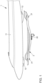
- Figure 1 shows the front hood 1 of a car with an outer skin 11 and a lock bridge 2.
- Lock bridge 2 and front hood 1 are not yet connected.
- the front hood 1 has two Attachment points 12 to which the castle bridge 2 is attached.
- the lock bridge 2 has two stop buffers 21. In the middle between the two stop buffers 21, the lock bridge 2 has a lock element 22. When the front hood 1 is closed, the lock bridge 2 is fixed by the lock element 22 and the stop buffers 21.
- the stop buffers 21 are arranged in the end regions of the castle bridge 2.
- the lock bridge 2 is shaped in such a way that there is a clear distance between the outer skin 11 of the front hood 1 and the lock bridge 2 between the stop buffers 21, in the area of the lock element 22.
- FIG. 2 shows the inside of the front hood 1.
- the front hood 1 has reinforcing elements 13 on the inside. These are cohesively connected to the outer skin 11 by means of welding.
- the lock bridge 2 is attached to the attachment points 12 of the front hood 1 via fasteners 3 which are arranged in the stop buffers 21.
- the reinforcing elements 13 are made weaker in the area between the lock bridge 2 in order to enable the outer skin 11 of the front hood 1 to be easily deformed in this area.
Landscapes
- Engineering & Computer Science (AREA)
- Mechanical Engineering (AREA)
- Chemical & Material Sciences (AREA)
- Combustion & Propulsion (AREA)
- Transportation (AREA)
- Superstructure Of Vehicle (AREA)
- Body Structure For Vehicles (AREA)
Description
- Die Erfindung betrifft eine Fronthaube für ein Fahrzeug.
- Bei der Fahrzeugentwicklung spielt der Fußgängerschutz eine immer wichtigere Rolle. Dies führt auch zu gestiegenen Anforderungen an die Gestaltung von Fronthauben für Kraftfahrzeuge. So müssen Fronthauben neben den bekannten Anforderungen basierend auf Windlasten, dem Zuschlagen und dem Verhindern von Flattern der Haube nun zusätzlich im Bereich des vorn liegenden Schlosses die Energie eines Fußgängeraufpralls absorbieren und den Fußgänger schützen.
- Es sind Systeme bekannt, die die Fronthaube im Falle eines Fußgängeraufpralles anheben, um so eine Knautschzone zur Aufnahme der Aufprallenergie des Fußgängers zu schaffen. Zudem ist bekannt, einen Scheibenairbag einzusetzen, der den Bereich der Frontscheibe und der A-Säule abdeckt, um im Falle eines frontalen Fußgängerunfalles den Kopf des Fußgängers vor einer Kollision mit diesen Bereichen zu schützen. Diese Maßnahmen sind sehr kostenintensiv und benötigen als aktive Komponenten zudem nachteilig eine Wartung und Funktionskontrolle.
- In der
DE 10 2014 003 199 A1 wird eine Fronthaube für ein Fahrzeug vorgeschlagen, die einen äußeren Rahmen und eine mittig angeordnete Öffnung dieses Rahmens aufweist. Die mittig angeordnete Öffnung des Rahmens wird dabei von Spriegeln überspannt. - In der
DE 199 11 833 A1 wird ein Vorderwagenbereich eines Kraftfahrzeuges vorgestellt, der den Fußgängerschutz verbessern soll. Hierfür werden die dort befindlichen Bauteile, unter anderem also die Fronthaube, mittels Stoßabsorptionselementen befestigt, um Aufprallenergie aufnehmen zu können. -
EP 1 557 340 A1 offenbart eine Fronthaube für ein Fahrzeug, umfassend eine Schlossbrücke, die sich quer zur Fahrzeuglängsrichtung erstreckt und ein Schlosselement aufweist, wobei die Schlossbrücke an mindestens zwei voneinander beabstandet angeordneten Befestigungspunkten mit der Fronthaube verbunden ist. Die Befestigung erfolgt über massive Befestigungselemente. - Der Erfindung liegt nun die Aufgabe zugrunde, eine Fronthaube für Fahrzeuge vorzuschlagen, die einen hohen Fußgängerschutz gewährleistet, einfach und kostengünstig herzustellen ist und eine geringe Ausfallwahrscheinlichkeit aufweist.
- Die oben genannte Aufgabe wird durch die Merkmale des Anspruchs 1 gelöst.
- Eine Fronthaube eines Fahrzeuges hat eine Außenhaut, zumeist mit auf der Innenseite angeordneten Verstärkungselementen. Diese sind dabei häufig stoffschlüssig mit der Außenhaut verbunden. Die Verstärkungselemente versteifen die Außenhaut und sollen ein Verbiegen der Fronthaube aufgrund von Windbelastungen oder auch ein Flattern durch eine dynamische Anregung verhindern.
- Gleichfalls relevante Lastfälle sind das Öffnen und Schließen der Fronthaube oder auch Windbelastungen im geöffneten Zustand. Hier sind insbesondere auch Torsionsbelastungen, die beispielsweise durch eine seitliche Krafteinleitung in die Fronthaube zum Öffnen oder Schließen auftreten, zu berücksichtigen. Diese Gründe sprechen für eine möglichst steife Auslegung der Fronthaube.
- Demgegenüber wird durch eine weiche Ausgestaltung der Fronthaube der Fußgängerschutz begünstigt.
- Die erfindungsgemäße Fronthaube für ein Fahrzeug weist eine Schlossbrücke auf. Diese erstreckt sich quer zur Fahrzeuglängsrichtung und ist innenseitig an der Fronthaube angeordnet. Bevorzugt ist die Schlossbrücke auf der Innenseite der Fronthaube im in Fahrtrichtung vorderen Bereich angeordnet. Besonders bevorzugt ist die Schlossbrücke symmetrisch bezogen auf die Außenhaut der Fronthaube angeordnet.
- Zur Klarstellung wird festgehalten, dass die Innenseite die dem Fahrzeuginnenraum zugewandte Seite der Fronthaube ist, also beispielsweise bei einer Motorhaube die dem Motor zugewandte Seite.
- Erfindungsgemäß weist die Schlossbrücke ein Schlosselement auf. Das Schlosselement stellt eine lösbare Verbindung der Fronthaube mit dem Fahrzeug her, die durch ein Bedienelement lösbar ist.
- Die Schlossbrücke ist dabei über mindestens zwei Befestigungspunkte mit der Fronthaube verbunden. Die Befestigungspunkte sind möglichst weit beabstandet angeordnet, um seitliche Krafteinleitungen sicher aufzunehmen. So wird vorteilhaft eine sichere Halterung der Motorhaube gewährleistet. Die Verbindung der Schlossbrücke erfolgt dabei bevorzugt mit den Verstärkungselementen der Fronthaube, da so vorteilhaft eine gute Krafteinleitung in die Fronthaube gewährleistet ist. Sie kann aber auch mit der Außenhaut der Fronthaube erfolgen.
- Vorteilhaft kann durch den Einsatz einer Schlossbrücke eine zusätzliche Knautschzone als Fußgängerschutz geschaffen werden. Besonders vorteilhaft ist diese Knautschzone in dem für den Fußgängerschutz besonders relevanten Bereich angeordnet.
- Erfindungsgemäß weist die Schlossbrücke mindestens eine Sollbruchstelle auf. Diese Sollbruchstelle führt zu einem Bruch der Schlossbrücke bei einer bestimmten Belastung und ermöglicht so vorteilhaft ein "Eintauchen" der Fronthaube im Kollisionsfall. Vorteilhaft kann so die Fronthaube um den von der Schlossbrücke geschaffenen Abstand eintauchen und dadurch die Energie eines Fußgängeraufpralls aufnehmen.
- In einer weiterhin bevorzugten Ausgestaltung der Erfindung weisen die mindestens zwei Befestigungspunkte einen Abstand von mindestens einem Viertel, weiter bevorzugt von mindestens einem Drittel und besonders bevorzugt von mindestens der Hälfte der Gesamtbreite der Fronthaube auf. Vorteilhaft kann so eine sichere Halterung, insbesondere eine sichere Aufnahme von Torsionsbelastungen, der Fronthaube gewährleistet werden.
- Die Beabstandung der mindestens zwei Befestigungselemente ermöglicht vorteilhaft eine weichere Auslegung von Außenhaut und Verstärkungselementen in dem Bereich dazwischen. So kann in diesem für Fußgängerkollisionen sehr relevanten Bereich eine zusätzliche Knautschzone geschaffen werden.
- In einer weiteren bevorzugten Ausgestaltung sind Außenhaut, Verstärkungselemente und/oder die Schlossbrücke so ausgestaltet, dass im Bereich zwischen den Befestigungspunkten zumindest teilweise ein Abstand zwischen Außenhaut beziehungsweise Verstärkungselementen und der Schlossbrücke ausgebildet ist. Dieser Abstand dient vorteilhaft als weitere Knautschzone und ermöglicht eine homogene Kraftaufnahme durch Deformation der Außenhaut, ohne dass die Schlossbrücke die Deformation der Außenhaut stört. Vorteilhaft kann so der Fußgängerschutz weiter verbessert werden.
- Die Schlossbrücke ist dabei bevorzugt ein längliches, trägerförmiges Bauteil, das in der Lage ist, Kräfte zwischen den Befestigungspunkten und dem Schlosselement zu übertragen. Dabei ist die Schlossbrücke bevorzugt möglichst flach, um den geringen Bauraum zwischen Fronthaube und beispielsweise darunter befindlicher Fahrzeugtechnik oder einem Kofferraum zu ermöglichen. In einer bevorzugten Ausgestaltung hat die Schlossbrücke einen u- oder wannenförmigen Querschnitt. Dabei ist die Schlossbrücke in ihren Endbereichen mit der Fronthaube verbunden, so dass sich im mittleren Bereich ein Abstand zwischen Fronthaube und Schlossbrücke einstellt, der eine Knautschzone für den Fußgängerschutz darstellt.
- In einer alternativen Ausgestaltung kann die Schlossbrücke auch ein flächiges Element sein, das an mehr als zwei Befestigungspunkten mit der Außenhaut oder den Verstärkungselementen verbunden ist.
- Weiterhin bevorzugt hat die Schlossbrücke Puffer für die Verbindung mit dem Fahrzeug. Diese Puffer stellen Auflagepunkte der Fronthaube im geschlossenen Zustand dar, so dass vorteilhaft die Fronthaube unbeweglich verankert ist und dynamische Anregungen nicht zu einem Flattern führen.
- Bevorzugt ist die Schlossbrücke aus Stahl gefertigt. Stahl ist vorteilhaft kostengünstig. In einer alternativen Ausgestaltung kann die Schlossbrücke auch aus Kunststoff, insbesondere faserverstärktem Kunststoff, gefertigt sein. Neben einem vorteilhaft geringen Gewicht können zudem die Eigenschaften von Kunststoffbauteilen hervorragend eingestellt werden.
- In einer besonders bevorzugten Ausgestaltung der Erfindung erfolgt die Verbindung der Schlossbrücke mit der Fronthaube mittels deformierbarer und/oder versagender Befestigungselemente. Diese deformierbaren und/oder versagenden Befestigungselemente sind dabei so ausgelegt, dass normale Lastzustände wie beispielsweise Windbelastungen oder Krafteinleitungen zum Öffnen und Schließen sicher abgefangen werden. Eine die normalen Lastzustände übersteigende Belastung führt zum Versagen der Befestigungselemente. Dieses Versagen kann dabei zu einer Deformation oder auch einer Zerstörung der Befestigungselemente führen und damit zu einer Beweglichkeit oder auch Deformierbarkeit der Fronthaube, die es vorteilhaft ermöglicht, Energie, beispielweise die Aufprallenergie eines Fußgängers, zu absorbieren.
- Die Deformierbarkeit beziehungsweise das definierte Versagen der Befestigungselemente wird dabei beispielsweise durch die Materialauswahl und die Gestaltung der Befestigungselemente realisiert. So können beispielsweise die Befestigungselemente eine Sollbruchstelle aufweisen und/oder aus einem Material gefertigt sein, das bei einer bestimmten Belastung versagt.
- Vorteilhaft kann so für den Lastfall einer Kollision, insbesondere mit einem Fußgänger, durch das Versagen oder die Deformation der Befestigungselemente eine die Kollisionsenergie absorbierende Struktur bereitgestellt werden. Diese Struktur kann Aufprallenergie aufnehmen und Fußgänger so vor Verletzungen schützen.
- Die Befestigungselemente sind dabei bevorzugt aus Kunststoff, Stahl oder Aluminium gefertigt. Diese Materialien sind vorteilhaft gut auf eine Lastgrenze einstellbar und langlebig.
- In einer weiteren bevorzugten Ausgestaltung ist das Schlosselement mittels deformierbarer und/oder versagender Bauteile mit der Schlossbrücke verbunden. So kann vorteilhaft die Deformierbarkeit der Fronthaube im Kollisionsfall und damit der Fußgängerschutz weiter verbessert werden.
- In einer weiterhin bevorzugten Ausgestaltung ist das Schlosselement selbst ein deformierbares und/oder versagendes Bauteil. So kann vorteilhaft der Montageaufwand verringert werden.
- Das erfindungsgemäße Kraftfahrzeug weist eine erfindungsgemäße Fronthaube auf.
- Weitere bevorzugte Ausgestaltungen der Erfindung ergeben sich aus den übrigen, in den Unteransprüchen genannten Merkmalen.
- Die verschiedenen in dieser Anmeldung genannten Ausführungsformen der Erfindung sind, sofern im Einzelfall nicht anders ausgeführt, mit Vorteil miteinander kombinierbar.
- Die Erfindung wird nachfolgend in Ausführungsbeispielen anhand der zugehörigen Zeichnungen erläutert. Es zeigen:
- Figur 1
- eine Fronthaube eines Fahrzeuges und eine Schlossbrücke und
- Figur 2
- eine Ansicht der Innenseite einer Fronthaube mit Schlossbrücke.
-
Figur 1 zeigt die Fronthaube 1 eines PKW mit einer Außenhaut 11 und eine Schlossbrücke 2. Schlossbrücke 2 und Fronthaube 1 sind noch nicht verbunden. Die Fronthaube 1 hat zwei Befestigungspunkte 12, an denen die Schlossbrücke 2 befestigt wird. Die Schlossbrücke 2 hat zwei Anschlagpuffer 21. Mittig zwischen den beiden Anschlagpuffern 21 hat die Schlossbrücke 2 ein Schlosselement 22. Im geschlossenen Zustand der Fronthaube 1 wird die Schlossbrücke 2 durch das Schlosselement 22 und die Anschlagpuffer 21 fixiert. - Die Anschlagpuffer 21 sind in den Endbereichen der Schlossbrücke 2 angeordnet. Die Schlossbrücke 2 ist derart geformt, dass zwischen den Anschlagpuffern 21, im Bereich des Schlosselementes 22, ein deutlicher Abstand zwischen der Außenhaut 11 der Fronthaube 1 und der Schlossbrücke 2 besteht.
-
Figur 2 zeigt die Innenseite der Fronthaube 1. Innenseitig weist die Fronthaube 1 Verstärkungselemente 13 auf. Diese sind stoffschlüssig mittels Schweißen mit der Außenhaut 11 verbunden. Die Schlossbrücke 2 ist mit den Befestigungspunkten 12 der Fronthaube 1 über Befestigungsmittel 3, die in den Anschlagpuffern 21 angeordnet sind, befestigt. - Die Verstärkungselemente 13 sind im Bereich zwischen der Schlossbrücke 2 schwächer ausgebildet, um in diesem Bereich eine gute Deformierbarkeit der Außenhaut 11 der Fronthaube 1 zu ermöglichen.
-
- 1
- Fronthaube
- 11
- Außenhaut
- 12
- Befestigungspunkte
- 13
- Verstärkungselemente
- 2
- Schlossbrücke
- 21
- Anschlagpuffer
- 22
- Schlosselement
- 3
- Befestigungsmittel/Befestigungselemente
Claims (9)
- Fronthaube (1) für eine Fahrzeug, umfassend eine Schlossbrücke (2), die sich quer zur Fahrzeuglängsrichtung erstreckt und ein Schlosselement (22) aufweist, wobei die Schlossbrücke (2) an mindestens zwei voneinander beabstandet angeordneten Befestigungspunkten (12) mit der Fronthaube (1) verbunden ist, dadurch gekennzeichnet, dass die Schlossbrücke (2) mindestens eine Sollbruchstelle aufweist.
- Fronthaube (1) nach Anspruch 1, dadurch gekennzeichnet, dass die Schlossbrücke (2) mit der Fronthaube (1) mittels deformierbarer und/oder versagender Befestigungselemente (3) verbunden ist.
- Fronthaube (1) nach Anspruch 2, dadurch gekennzeichnet, dass die Befestigungselemente (3) aus Kunststoff, Stahl oder Aluminium gefertigt sind.
- Fronthaube (1) nach einem der vorangehenden Ansprüche, dadurch gekennzeichnet, dass der Abstand der mindestens zwei Befestigungspunkte (12) mindestens ein Drittel der Gesamtbreite der Fronthaube (1) beträgt.
- Fronthaube (1) nach einem der vorangehenden Ansprüche, dadurch gekennzeichnet, dass das Schlosselement (22) mittels deformierbarer und/oder versagender Befestigungsmittel (3) mit der Schlossbrücke (2) verbunden ist.
- Fronthaube (1) nach einem der vorangehenden Ansprüche, dadurch gekennzeichnet, dass das Schlosselement (22) ein deformierbares und/oder versagendes Bauteil ist.
- Fronthaube (1) nach einem der vorangehenden Ansprüche, dadurch gekennzeichnet, dass die Schlossbrücke (2) in einem Bereich zur Fronthaube (1) beabstandet ist.
- Fronthaube (1) nach einem der vorangehenden Ansprüche, dadurch gekennzeichnet, dass die Schlossbrücke (2) Anschlagpuffer (21) für die Verbindung mit dem Fahrzeug aufweist.
- Kraftfahrzeug aufweisend eine Fronthaube (1) nach einem der vorangehenden Ansprüche.
Applications Claiming Priority (2)
| Application Number | Priority Date | Filing Date | Title |
|---|---|---|---|
| DE102019200765.1A DE102019200765A1 (de) | 2019-01-23 | 2019-01-23 | Fronthaube für ein Fahrzeug |
| PCT/EP2020/050963 WO2020152014A1 (de) | 2019-01-23 | 2020-01-16 | Fronthaube für ein fahrzeug |
Publications (2)
| Publication Number | Publication Date |
|---|---|
| EP3914484A1 EP3914484A1 (de) | 2021-12-01 |
| EP3914484B1 true EP3914484B1 (de) | 2023-10-04 |
Family
ID=69190756
Family Applications (1)
| Application Number | Title | Priority Date | Filing Date |
|---|---|---|---|
| EP20701701.3A Active EP3914484B1 (de) | 2019-01-23 | 2020-01-16 | Fronthaube für ein fahrzeug |
Country Status (5)
| Country | Link |
|---|---|
| US (1) | US12128954B2 (de) |
| EP (1) | EP3914484B1 (de) |
| CN (1) | CN113015660B (de) |
| DE (1) | DE102019200765A1 (de) |
| WO (1) | WO2020152014A1 (de) |
Families Citing this family (6)
| Publication number | Priority date | Publication date | Assignee | Title |
|---|---|---|---|---|
| CN113316537B (zh) * | 2019-01-10 | 2023-08-01 | 日本制铁株式会社 | 汽车发动机罩 |
| US11884332B2 (en) * | 2019-01-10 | 2024-01-30 | Nippon Steel Corporation | Automobile hood |
| US11286005B2 (en) * | 2019-09-03 | 2022-03-29 | Honda Motor Co., Ltd. | Hood frame reinforcement for deflection mitigation |
| WO2021200860A1 (ja) * | 2020-03-30 | 2021-10-07 | 日本製鉄株式会社 | 自動車フード |
| CN114991600B (zh) * | 2022-06-29 | 2024-09-27 | 长城汽车股份有限公司 | 发动机罩锁安装结构及汽车 |
| DE102022208508A1 (de) * | 2022-08-16 | 2024-02-22 | Psa Automobiles Sa | Verstärkungsbauteil und Haubenanordnung für ein Kraftfahrzeug |
Citations (2)
| Publication number | Priority date | Publication date | Assignee | Title |
|---|---|---|---|---|
| DE3734992C2 (de) * | 1987-10-15 | 1989-12-14 | Ohi Seisakusho Co., Ltd., Yokohama, Kanagawa, Jp | |
| WO2013175086A1 (fr) * | 2012-05-24 | 2013-11-28 | Peugeot Citroen Automobiles Sa | Structure de l'avant d'un véhicule automobile permettant d'amortir le choc de la tête d'un piéton contre le capot |
Family Cites Families (33)
| Publication number | Priority date | Publication date | Assignee | Title |
|---|---|---|---|---|
| US3733958A (en) * | 1969-12-10 | 1973-05-22 | Standard Pressed Steel Co | Collar assembly for use with a rivet |
| DE2221192C3 (de) * | 1972-04-29 | 1981-08-13 | Daimler-Benz Ag, 7000 Stuttgart | Befestigung der Ränder von Innenverkleidungen von Kraftfahrzeugdächern |
| US4490083A (en) * | 1980-01-10 | 1984-12-25 | Russell, Burdsall, & Ward Corporation | Sealing capped nut and bolt therefor |
| DE3035352A1 (de) * | 1980-09-19 | 1982-05-06 | Volkswagenwerk Ag, 3180 Wolfsburg | Vorderer kraftfahrzeug-endbereich |
| JP3957874B2 (ja) * | 1998-05-13 | 2007-08-15 | 本田技研工業株式会社 | 自動車のボンネット |
| DE19911833C2 (de) | 1999-03-17 | 2003-12-18 | Audi Ag | Vorderwagenbereich für ein Kraftfahrzeug |
| JP2002037129A (ja) * | 2000-07-24 | 2002-02-06 | Isuzu Motors Ltd | エンジンフードロック廻りの構造 |
| KR20020039757A (ko) * | 2000-11-22 | 2002-05-30 | 이계안 | 자동차의 충격완충용 후드 로크장치 |
| US6810978B2 (en) * | 2002-07-09 | 2004-11-02 | International Truck Intellectual Property Company, Llc | Assembly with locating-point inserts integrally molded or cast into locating structures |
| JP4021723B2 (ja) * | 2002-08-08 | 2007-12-12 | ダイハツ工業株式会社 | フードロックストライカ構造 |
| DE10331845B4 (de) * | 2003-07-14 | 2012-05-10 | Gm Global Technology Operations Llc (N.D.Ges.D. Staates Delaware) | Fahrzeugkarosserie mit Aktuatoren zur Anhebung eines Karosserieelements |
| FR2858589B1 (fr) * | 2003-08-04 | 2006-12-01 | Cera | Panneau de renfort multifonction d'un capot de vehicule automobile |
| DE102004009470A1 (de) * | 2004-02-27 | 2005-09-15 | Daimlerchrysler Ag | Sicherheitsvorrichtung |
| JP2007022204A (ja) * | 2005-07-13 | 2007-02-01 | Nissan Motor Co Ltd | 自動車のフード構造 |
| JP2007030737A (ja) * | 2005-07-28 | 2007-02-08 | Toyota Motor Corp | 車両用フード構造 |
| US7677539B2 (en) * | 2006-02-23 | 2010-03-16 | Barnes Group Inc. | Force control strut |
| ES2488398T3 (es) * | 2006-11-23 | 2014-08-27 | Compagnie Plastic Omnium | Forro de capó de un vehículo automóvil y sus combinaciones con algunas partes del vehículo |
| JP5207228B2 (ja) * | 2007-10-11 | 2013-06-12 | 株式会社神戸製鋼所 | 車両用インナパネル |
| GB2480798B (en) * | 2010-02-18 | 2016-01-27 | Ford Global Tech Llc | A bonnet for a vehicle |
| CN102822040B (zh) * | 2010-03-26 | 2015-01-14 | 丰田自动车株式会社 | 车辆用机罩结构 |
| DE102011012529A1 (de) | 2011-02-26 | 2012-08-30 | Gm Global Technology Operations, Llc | Anordnung mit einem Schlossquerträger und einem Haubenschloss für ein Kraftfahrzeug |
| JP5649527B2 (ja) * | 2011-07-01 | 2015-01-07 | 株式会社神戸製鋼所 | 車両用フード |
| US20130087401A1 (en) * | 2011-10-05 | 2013-04-11 | GM Global Technology Operations LLC | Vehicle hood assembly and method for rapidly elevating the hood |
| DE102012012108A1 (de) * | 2012-06-19 | 2013-12-19 | GM Global Technology Operations, LLC (n.d. Ges. d. Staates Delaware) | Kraftfahrzeugkarosserie |
| US8720975B1 (en) * | 2012-12-19 | 2014-05-13 | Ford Global Technologies, Llc | Integrated hood bump-stop and headlamp attachment for pedestrian protection |
| DE102014003199A1 (de) | 2014-03-04 | 2015-09-10 | GM Global Technology Operations LLC (n. d. Ges. d. Staates Delaware) | Fronthaube für ein Kraftfahrzeug |
| DE102014018066B4 (de) * | 2014-12-08 | 2022-05-19 | Audi Ag | Grundplatte, Schließvorrichtung und zugehöriges Kraftfahrzeug |
| US20170232926A1 (en) * | 2016-02-12 | 2017-08-17 | Ford Global Technologies, Llc | Vehicle hood assembly with deployable pedestrian protection |
| FR3047962B1 (fr) * | 2016-02-24 | 2018-02-23 | Peugeot Citroen Automobiles Sa | Structure avant d’un vehicule automobile comportant une gache qui comporte une partie superieure et une partie inferieure deformable, gache correspondante et procede de fabrication d’une telle gache |
| JP6601439B2 (ja) * | 2017-02-23 | 2019-11-06 | スズキ株式会社 | 車両用フロントフード |
| WO2019104339A1 (en) * | 2017-11-27 | 2019-05-31 | Sps Technologies, Llc | Two-piece blind fastener |
| JP7232730B2 (ja) * | 2019-06-28 | 2023-03-03 | トヨタ自動車東日本株式会社 | フードロック構造 |
| CN211568079U (zh) * | 2019-12-10 | 2020-09-25 | 宁波吉利汽车研究开发有限公司 | 一种转向管柱护罩的安装结构 |
-
2019
- 2019-01-23 DE DE102019200765.1A patent/DE102019200765A1/de active Pending
-
2020
- 2020-01-16 WO PCT/EP2020/050963 patent/WO2020152014A1/de not_active Ceased
- 2020-01-16 CN CN202080006176.1A patent/CN113015660B/zh active Active
- 2020-01-16 EP EP20701701.3A patent/EP3914484B1/de active Active
-
2021
- 2021-07-22 US US17/383,011 patent/US12128954B2/en active Active
Patent Citations (2)
| Publication number | Priority date | Publication date | Assignee | Title |
|---|---|---|---|---|
| DE3734992C2 (de) * | 1987-10-15 | 1989-12-14 | Ohi Seisakusho Co., Ltd., Yokohama, Kanagawa, Jp | |
| WO2013175086A1 (fr) * | 2012-05-24 | 2013-11-28 | Peugeot Citroen Automobiles Sa | Structure de l'avant d'un véhicule automobile permettant d'amortir le choc de la tête d'un piéton contre le capot |
Also Published As
| Publication number | Publication date |
|---|---|
| CN113015660A (zh) | 2021-06-22 |
| EP3914484A1 (de) | 2021-12-01 |
| US20210347414A1 (en) | 2021-11-11 |
| CN113015660B (zh) | 2023-08-08 |
| US12128954B2 (en) | 2024-10-29 |
| WO2020152014A1 (de) | 2020-07-30 |
| DE102019200765A1 (de) | 2020-07-23 |
Similar Documents
| Publication | Publication Date | Title |
|---|---|---|
| EP3914484B1 (de) | Fronthaube für ein fahrzeug | |
| DE19922107C1 (de) | Fronthaubenanordnung | |
| EP1178914B1 (de) | Fronthaubenanordnung | |
| EP4001022A1 (de) | Stossfängeranordnung | |
| EP4157660B1 (de) | Personenkraftwagen mit verbessertem seitenaufprallschutz | |
| EP2931543B1 (de) | Dachmodul für ein fahrzeugdach eines personenkraftwagens | |
| DE102013011189C5 (de) | Kraftwagenbug eines Personenkraftwagens | |
| EP1637411B1 (de) | Anordnung einer Frontklappe an einem Fahrzeug | |
| DE102006015403B4 (de) | Fronthaube für einen Personenkraftwagen | |
| DE102017114652B4 (de) | Schutzvorrichtung zum Schutz von Verkehrsteilnehmern außerhalb eines Kraftfahrzeugs und Verfahren zum Betreiben einer Schutzvorrichtung | |
| DE202008007671U1 (de) | Vorderbau für ein Kraftfahrzeug | |
| DE10037628A1 (de) | Motorhaube für Fahrzeuge | |
| EP2686210B1 (de) | Beschlagteil | |
| EP1703059A1 (de) | Anschlagpuffer für eine Frontklappe eines Kraftfahrzeugs | |
| DE102011050514B4 (de) | Türrahmen einer Kraftfahrzeugtür und Crashpad | |
| DE102008014767A1 (de) | Schutzeinrichtung an der Frontklappe eines Kraftfahrzeugs | |
| EP1777145B1 (de) | Windschutzscheibenanordnung | |
| DE102004027782B3 (de) | Sicherheitsvorrichtung | |
| DE102006055489B4 (de) | Sicherheitseinrichtung an einem Fahrzeug | |
| DE102014115735B4 (de) | Stützanordnung zur Abstützung einer schwenkbaren Fronthaube eines Kraftfahrzeugs | |
| DE20023228U1 (de) | Fronthaubenanordnung | |
| DE102017217095A1 (de) | Fahrzeug, insbesondere Kraftfahrzeug, mit einem einer Seitentür zugeordneten Blockiermittel | |
| DE102014001948A1 (de) | Fahrzeug mit einer Motorhaube | |
| DE102015003534B3 (de) | Deformationsvorrichtung für ein Kraftfahrzeug und Kraftfahrzeug | |
| DE102012007737A1 (de) | Befestigungsanordnung eines Stoßfängerelements an einem Rohbau einer Personenkraftwagenkarosserie |
Legal Events
| Date | Code | Title | Description |
|---|---|---|---|
| STAA | Information on the status of an ep patent application or granted ep patent |
Free format text: STATUS: UNKNOWN |
|
| STAA | Information on the status of an ep patent application or granted ep patent |
Free format text: STATUS: THE INTERNATIONAL PUBLICATION HAS BEEN MADE |
|
| PUAI | Public reference made under article 153(3) epc to a published international application that has entered the european phase |
Free format text: ORIGINAL CODE: 0009012 |
|
| STAA | Information on the status of an ep patent application or granted ep patent |
Free format text: STATUS: REQUEST FOR EXAMINATION WAS MADE |
|
| 17P | Request for examination filed |
Effective date: 20210823 |
|
| AK | Designated contracting states |
Kind code of ref document: A1 Designated state(s): AL AT BE BG CH CY CZ DE DK EE ES FI FR GB GR HR HU IE IS IT LI LT LU LV MC MK MT NL NO PL PT RO RS SE SI SK SM TR |
|
| DAV | Request for validation of the european patent (deleted) | ||
| DAX | Request for extension of the european patent (deleted) | ||
| STAA | Information on the status of an ep patent application or granted ep patent |
Free format text: STATUS: EXAMINATION IS IN PROGRESS |
|
| 17Q | First examination report despatched |
Effective date: 20221114 |
|
| GRAP | Despatch of communication of intention to grant a patent |
Free format text: ORIGINAL CODE: EPIDOSNIGR1 |
|
| STAA | Information on the status of an ep patent application or granted ep patent |
Free format text: STATUS: GRANT OF PATENT IS INTENDED |
|
| INTG | Intention to grant announced |
Effective date: 20230628 |
|
| GRAS | Grant fee paid |
Free format text: ORIGINAL CODE: EPIDOSNIGR3 |
|
| GRAA | (expected) grant |
Free format text: ORIGINAL CODE: 0009210 |
|
| STAA | Information on the status of an ep patent application or granted ep patent |
Free format text: STATUS: THE PATENT HAS BEEN GRANTED |
|
| AK | Designated contracting states |
Kind code of ref document: B1 Designated state(s): AL AT BE BG CH CY CZ DE DK EE ES FI FR GB GR HR HU IE IS IT LI LT LU LV MC MK MT NL NO PL PT RO RS SE SI SK SM TR |
|
| REG | Reference to a national code |
Ref country code: GB Ref legal event code: FG4D Free format text: NOT ENGLISH |
|
| REG | Reference to a national code |
Ref country code: CH Ref legal event code: EP |
|
| REG | Reference to a national code |
Ref country code: DE Ref legal event code: R096 Ref document number: 502020005513 Country of ref document: DE |
|
| REG | Reference to a national code |
Ref country code: IE Ref legal event code: FG4D Free format text: LANGUAGE OF EP DOCUMENT: GERMAN |
|
| P01 | Opt-out of the competence of the unified patent court (upc) registered |
Effective date: 20231016 |
|
| REG | Reference to a national code |
Ref country code: LT Ref legal event code: MG9D |
|
| REG | Reference to a national code |
Ref country code: NL Ref legal event code: MP Effective date: 20231004 |
|
| PG25 | Lapsed in a contracting state [announced via postgrant information from national office to epo] |
Ref country code: NL Free format text: LAPSE BECAUSE OF FAILURE TO SUBMIT A TRANSLATION OF THE DESCRIPTION OR TO PAY THE FEE WITHIN THE PRESCRIBED TIME-LIMIT Effective date: 20231004 |
|
| PG25 | Lapsed in a contracting state [announced via postgrant information from national office to epo] |
Ref country code: GR Free format text: LAPSE BECAUSE OF FAILURE TO SUBMIT A TRANSLATION OF THE DESCRIPTION OR TO PAY THE FEE WITHIN THE PRESCRIBED TIME-LIMIT Effective date: 20240105 |
|
| PG25 | Lapsed in a contracting state [announced via postgrant information from national office to epo] |
Ref country code: IS Free format text: LAPSE BECAUSE OF FAILURE TO SUBMIT A TRANSLATION OF THE DESCRIPTION OR TO PAY THE FEE WITHIN THE PRESCRIBED TIME-LIMIT Effective date: 20240204 |
|
| PG25 | Lapsed in a contracting state [announced via postgrant information from national office to epo] |
Ref country code: LT Free format text: LAPSE BECAUSE OF FAILURE TO SUBMIT A TRANSLATION OF THE DESCRIPTION OR TO PAY THE FEE WITHIN THE PRESCRIBED TIME-LIMIT Effective date: 20231004 |
|
| PG25 | Lapsed in a contracting state [announced via postgrant information from national office to epo] |
Ref country code: ES Free format text: LAPSE BECAUSE OF FAILURE TO SUBMIT A TRANSLATION OF THE DESCRIPTION OR TO PAY THE FEE WITHIN THE PRESCRIBED TIME-LIMIT Effective date: 20231004 |
|
| PG25 | Lapsed in a contracting state [announced via postgrant information from national office to epo] |
Ref country code: LT Free format text: LAPSE BECAUSE OF FAILURE TO SUBMIT A TRANSLATION OF THE DESCRIPTION OR TO PAY THE FEE WITHIN THE PRESCRIBED TIME-LIMIT Effective date: 20231004 Ref country code: IS Free format text: LAPSE BECAUSE OF FAILURE TO SUBMIT A TRANSLATION OF THE DESCRIPTION OR TO PAY THE FEE WITHIN THE PRESCRIBED TIME-LIMIT Effective date: 20240204 Ref country code: GR Free format text: LAPSE BECAUSE OF FAILURE TO SUBMIT A TRANSLATION OF THE DESCRIPTION OR TO PAY THE FEE WITHIN THE PRESCRIBED TIME-LIMIT Effective date: 20240105 Ref country code: ES Free format text: LAPSE BECAUSE OF FAILURE TO SUBMIT A TRANSLATION OF THE DESCRIPTION OR TO PAY THE FEE WITHIN THE PRESCRIBED TIME-LIMIT Effective date: 20231004 Ref country code: BG Free format text: LAPSE BECAUSE OF FAILURE TO SUBMIT A TRANSLATION OF THE DESCRIPTION OR TO PAY THE FEE WITHIN THE PRESCRIBED TIME-LIMIT Effective date: 20240104 Ref country code: PT Free format text: LAPSE BECAUSE OF FAILURE TO SUBMIT A TRANSLATION OF THE DESCRIPTION OR TO PAY THE FEE WITHIN THE PRESCRIBED TIME-LIMIT Effective date: 20240205 |
|
| PG25 | Lapsed in a contracting state [announced via postgrant information from national office to epo] |
Ref country code: SE Free format text: LAPSE BECAUSE OF FAILURE TO SUBMIT A TRANSLATION OF THE DESCRIPTION OR TO PAY THE FEE WITHIN THE PRESCRIBED TIME-LIMIT Effective date: 20231004 Ref country code: RS Free format text: LAPSE BECAUSE OF FAILURE TO SUBMIT A TRANSLATION OF THE DESCRIPTION OR TO PAY THE FEE WITHIN THE PRESCRIBED TIME-LIMIT Effective date: 20231004 Ref country code: PL Free format text: LAPSE BECAUSE OF FAILURE TO SUBMIT A TRANSLATION OF THE DESCRIPTION OR TO PAY THE FEE WITHIN THE PRESCRIBED TIME-LIMIT Effective date: 20231004 Ref country code: NO Free format text: LAPSE BECAUSE OF FAILURE TO SUBMIT A TRANSLATION OF THE DESCRIPTION OR TO PAY THE FEE WITHIN THE PRESCRIBED TIME-LIMIT Effective date: 20240104 Ref country code: LV Free format text: LAPSE BECAUSE OF FAILURE TO SUBMIT A TRANSLATION OF THE DESCRIPTION OR TO PAY THE FEE WITHIN THE PRESCRIBED TIME-LIMIT Effective date: 20231004 Ref country code: HR Free format text: LAPSE BECAUSE OF FAILURE TO SUBMIT A TRANSLATION OF THE DESCRIPTION OR TO PAY THE FEE WITHIN THE PRESCRIBED TIME-LIMIT Effective date: 20231004 |
|
| REG | Reference to a national code |
Ref country code: DE Ref legal event code: R097 Ref document number: 502020005513 Country of ref document: DE |
|
| PG25 | Lapsed in a contracting state [announced via postgrant information from national office to epo] |
Ref country code: DK Free format text: LAPSE BECAUSE OF FAILURE TO SUBMIT A TRANSLATION OF THE DESCRIPTION OR TO PAY THE FEE WITHIN THE PRESCRIBED TIME-LIMIT Effective date: 20231004 |
|
| PG25 | Lapsed in a contracting state [announced via postgrant information from national office to epo] |
Ref country code: CZ Free format text: LAPSE BECAUSE OF FAILURE TO SUBMIT A TRANSLATION OF THE DESCRIPTION OR TO PAY THE FEE WITHIN THE PRESCRIBED TIME-LIMIT Effective date: 20231004 |
|
| PG25 | Lapsed in a contracting state [announced via postgrant information from national office to epo] |
Ref country code: SK Free format text: LAPSE BECAUSE OF FAILURE TO SUBMIT A TRANSLATION OF THE DESCRIPTION OR TO PAY THE FEE WITHIN THE PRESCRIBED TIME-LIMIT Effective date: 20231004 |
|
| PG25 | Lapsed in a contracting state [announced via postgrant information from national office to epo] |
Ref country code: SM Free format text: LAPSE BECAUSE OF FAILURE TO SUBMIT A TRANSLATION OF THE DESCRIPTION OR TO PAY THE FEE WITHIN THE PRESCRIBED TIME-LIMIT Effective date: 20231004 Ref country code: SK Free format text: LAPSE BECAUSE OF FAILURE TO SUBMIT A TRANSLATION OF THE DESCRIPTION OR TO PAY THE FEE WITHIN THE PRESCRIBED TIME-LIMIT Effective date: 20231004 Ref country code: RO Free format text: LAPSE BECAUSE OF FAILURE TO SUBMIT A TRANSLATION OF THE DESCRIPTION OR TO PAY THE FEE WITHIN THE PRESCRIBED TIME-LIMIT Effective date: 20231004 Ref country code: IT Free format text: LAPSE BECAUSE OF FAILURE TO SUBMIT A TRANSLATION OF THE DESCRIPTION OR TO PAY THE FEE WITHIN THE PRESCRIBED TIME-LIMIT Effective date: 20231004 Ref country code: EE Free format text: LAPSE BECAUSE OF FAILURE TO SUBMIT A TRANSLATION OF THE DESCRIPTION OR TO PAY THE FEE WITHIN THE PRESCRIBED TIME-LIMIT Effective date: 20231004 Ref country code: DK Free format text: LAPSE BECAUSE OF FAILURE TO SUBMIT A TRANSLATION OF THE DESCRIPTION OR TO PAY THE FEE WITHIN THE PRESCRIBED TIME-LIMIT Effective date: 20231004 Ref country code: CZ Free format text: LAPSE BECAUSE OF FAILURE TO SUBMIT A TRANSLATION OF THE DESCRIPTION OR TO PAY THE FEE WITHIN THE PRESCRIBED TIME-LIMIT Effective date: 20231004 |
|
| PLBE | No opposition filed within time limit |
Free format text: ORIGINAL CODE: 0009261 |
|
| STAA | Information on the status of an ep patent application or granted ep patent |
Free format text: STATUS: NO OPPOSITION FILED WITHIN TIME LIMIT |
|
| REG | Reference to a national code |
Ref country code: DE Ref legal event code: R082 Ref document number: 502020005513 Country of ref document: DE |
|
| PG25 | Lapsed in a contracting state [announced via postgrant information from national office to epo] |
Ref country code: MC Free format text: LAPSE BECAUSE OF FAILURE TO SUBMIT A TRANSLATION OF THE DESCRIPTION OR TO PAY THE FEE WITHIN THE PRESCRIBED TIME-LIMIT Effective date: 20231004 |
|
| PG25 | Lapsed in a contracting state [announced via postgrant information from national office to epo] |
Ref country code: MC Free format text: LAPSE BECAUSE OF FAILURE TO SUBMIT A TRANSLATION OF THE DESCRIPTION OR TO PAY THE FEE WITHIN THE PRESCRIBED TIME-LIMIT Effective date: 20231004 |
|
| REG | Reference to a national code |
Ref country code: CH Ref legal event code: PL |
|
| 26N | No opposition filed |
Effective date: 20240705 |
|
| PG25 | Lapsed in a contracting state [announced via postgrant information from national office to epo] |
Ref country code: LU Free format text: LAPSE BECAUSE OF NON-PAYMENT OF DUE FEES Effective date: 20240116 |
|
| PG25 | Lapsed in a contracting state [announced via postgrant information from national office to epo] |
Ref country code: LU Free format text: LAPSE BECAUSE OF NON-PAYMENT OF DUE FEES Effective date: 20240116 |
|
| PG25 | Lapsed in a contracting state [announced via postgrant information from national office to epo] |
Ref country code: BE Free format text: LAPSE BECAUSE OF NON-PAYMENT OF DUE FEES Effective date: 20240131 |
|
| PG25 | Lapsed in a contracting state [announced via postgrant information from national office to epo] |
Ref country code: CH Free format text: LAPSE BECAUSE OF NON-PAYMENT OF DUE FEES Effective date: 20240131 |
|
| PG25 | Lapsed in a contracting state [announced via postgrant information from national office to epo] |
Ref country code: SI Free format text: LAPSE BECAUSE OF FAILURE TO SUBMIT A TRANSLATION OF THE DESCRIPTION OR TO PAY THE FEE WITHIN THE PRESCRIBED TIME-LIMIT Effective date: 20231004 |
|
| PG25 | Lapsed in a contracting state [announced via postgrant information from national office to epo] |
Ref country code: SI Free format text: LAPSE BECAUSE OF FAILURE TO SUBMIT A TRANSLATION OF THE DESCRIPTION OR TO PAY THE FEE WITHIN THE PRESCRIBED TIME-LIMIT Effective date: 20231004 Ref country code: CH Free format text: LAPSE BECAUSE OF NON-PAYMENT OF DUE FEES Effective date: 20240131 Ref country code: BE Free format text: LAPSE BECAUSE OF NON-PAYMENT OF DUE FEES Effective date: 20240131 |
|
| REG | Reference to a national code |
Ref country code: BE Ref legal event code: MM Effective date: 20240131 |
|
| PG25 | Lapsed in a contracting state [announced via postgrant information from national office to epo] |
Ref country code: IE Free format text: LAPSE BECAUSE OF NON-PAYMENT OF DUE FEES Effective date: 20240116 |
|
| PG25 | Lapsed in a contracting state [announced via postgrant information from national office to epo] |
Ref country code: IE Free format text: LAPSE BECAUSE OF NON-PAYMENT OF DUE FEES Effective date: 20240116 |
|
| PGFP | Annual fee paid to national office [announced via postgrant information from national office to epo] |
Ref country code: AT Payment date: 20250417 Year of fee payment: 5 |
|
| PG25 | Lapsed in a contracting state [announced via postgrant information from national office to epo] |
Ref country code: CY Free format text: LAPSE BECAUSE OF FAILURE TO SUBMIT A TRANSLATION OF THE DESCRIPTION OR TO PAY THE FEE WITHIN THE PRESCRIBED TIME-LIMIT; INVALID AB INITIO Effective date: 20200116 |
|
| PG25 | Lapsed in a contracting state [announced via postgrant information from national office to epo] |
Ref country code: HU Free format text: LAPSE BECAUSE OF FAILURE TO SUBMIT A TRANSLATION OF THE DESCRIPTION OR TO PAY THE FEE WITHIN THE PRESCRIBED TIME-LIMIT; INVALID AB INITIO Effective date: 20200116 |
|
| PG25 | Lapsed in a contracting state [announced via postgrant information from national office to epo] |
Ref country code: FI Free format text: LAPSE BECAUSE OF FAILURE TO SUBMIT A TRANSLATION OF THE DESCRIPTION OR TO PAY THE FEE WITHIN THE PRESCRIBED TIME-LIMIT Effective date: 20231004 |
|
| PG25 | Lapsed in a contracting state [announced via postgrant information from national office to epo] |
Ref country code: TR Free format text: LAPSE BECAUSE OF FAILURE TO SUBMIT A TRANSLATION OF THE DESCRIPTION OR TO PAY THE FEE WITHIN THE PRESCRIBED TIME-LIMIT Effective date: 20231004 |
|
| REG | Reference to a national code |
Ref country code: AT Ref legal event code: MM01 Ref document number: 1617464 Country of ref document: AT Kind code of ref document: T Effective date: 20250116 |
|
| PGFP | Annual fee paid to national office [announced via postgrant information from national office to epo] |
Ref country code: GB Payment date: 20260126 Year of fee payment: 7 |
|
| PGFP | Annual fee paid to national office [announced via postgrant information from national office to epo] |
Ref country code: DE Payment date: 20260131 Year of fee payment: 7 |
|
| PG25 | Lapsed in a contracting state [announced via postgrant information from national office to epo] |
Ref country code: AT Free format text: LAPSE BECAUSE OF NON-PAYMENT OF DUE FEES Effective date: 20250116 |
|
| PGFP | Annual fee paid to national office [announced via postgrant information from national office to epo] |
Ref country code: FR Payment date: 20260126 Year of fee payment: 7 |