EP3912936A1 - Dispositif de guidage ainsi que dispositif de préhension et de transport permettant d'appréhender, de maintenir, de guider et de transporter des récipients de type bouteille - Google Patents
Dispositif de guidage ainsi que dispositif de préhension et de transport permettant d'appréhender, de maintenir, de guider et de transporter des récipients de type bouteille Download PDFInfo
- Publication number
- EP3912936A1 EP3912936A1 EP20175408.2A EP20175408A EP3912936A1 EP 3912936 A1 EP3912936 A1 EP 3912936A1 EP 20175408 A EP20175408 A EP 20175408A EP 3912936 A1 EP3912936 A1 EP 3912936A1
- Authority
- EP
- European Patent Office
- Prior art keywords
- gripping
- guide
- guide device
- setting plate
- transport device
- Prior art date
- Legal status (The legal status is an assumption and is not a legal conclusion. Google has not performed a legal analysis and makes no representation as to the accuracy of the status listed.)
- Pending
Links
Images

Classifications
-
- B—PERFORMING OPERATIONS; TRANSPORTING
- B65—CONVEYING; PACKING; STORING; HANDLING THIN OR FILAMENTARY MATERIAL
- B65G—TRANSPORT OR STORAGE DEVICES, e.g. CONVEYORS FOR LOADING OR TIPPING, SHOP CONVEYOR SYSTEMS OR PNEUMATIC TUBE CONVEYORS
- B65G47/00—Article or material-handling devices associated with conveyors; Methods employing such devices
- B65G47/74—Feeding, transfer, or discharging devices of particular kinds or types
- B65G47/84—Star-shaped wheels or devices having endless travelling belts or chains, the wheels or devices being equipped with article-engaging elements
- B65G47/846—Star-shaped wheels or wheels equipped with article-engaging elements
- B65G47/847—Star-shaped wheels or wheels equipped with article-engaging elements the article-engaging elements being grippers
-
- B—PERFORMING OPERATIONS; TRANSPORTING
- B65—CONVEYING; PACKING; STORING; HANDLING THIN OR FILAMENTARY MATERIAL
- B65G—TRANSPORT OR STORAGE DEVICES, e.g. CONVEYORS FOR LOADING OR TIPPING, SHOP CONVEYOR SYSTEMS OR PNEUMATIC TUBE CONVEYORS
- B65G47/00—Article or material-handling devices associated with conveyors; Methods employing such devices
- B65G47/74—Feeding, transfer, or discharging devices of particular kinds or types
- B65G47/90—Devices for picking-up and depositing articles or materials
- B65G47/904—Devices for picking-up and depositing articles or materials provided with rotary movements only
-
- B—PERFORMING OPERATIONS; TRANSPORTING
- B65—CONVEYING; PACKING; STORING; HANDLING THIN OR FILAMENTARY MATERIAL
- B65G—TRANSPORT OR STORAGE DEVICES, e.g. CONVEYORS FOR LOADING OR TIPPING, SHOP CONVEYOR SYSTEMS OR PNEUMATIC TUBE CONVEYORS
- B65G47/00—Article or material-handling devices associated with conveyors; Methods employing such devices
- B65G47/22—Devices influencing the relative position or the attitude of articles during transit by conveyors
-
- B—PERFORMING OPERATIONS; TRANSPORTING
- B65—CONVEYING; PACKING; STORING; HANDLING THIN OR FILAMENTARY MATERIAL
- B65G—TRANSPORT OR STORAGE DEVICES, e.g. CONVEYORS FOR LOADING OR TIPPING, SHOP CONVEYOR SYSTEMS OR PNEUMATIC TUBE CONVEYORS
- B65G2201/00—Indexing codes relating to handling devices, e.g. conveyors, characterised by the type of product or load being conveyed or handled
- B65G2201/02—Articles
- B65G2201/0235—Containers
- B65G2201/0244—Bottles
Definitions
- the invention relates to a guide device for a positioning plate of a gripping and transport device for containers.
- the invention also relates to a gripping and transport device for gripping, holding, guiding and transporting, in particular, bottle-like containers, with such a guide device as a height adjustment device.
- Gripping and transport devices for gripping, holding and / or guiding containers are already known from the prior art, in particular under the name "clip star". Gripping and transport devices have a large number of gripping devices with pairs of gripping arms. They are mainly used in the assembly line processing of containers or receptacles, which are intended in particular for filling with liquids or other bulk goods.
- Such container types can differ significantly from one another in their general shape, in particular in their height, their width or their diameter.
- An assembly line processing of large numbers of containers also makes an adjustment of the gripping and transport devices absolutely necessary in order to be able to guarantee safe handling by the gripping and transport device and to avoid rejects in the sense of incorrect filling, incorrect labeling or destroyed containers.
- the invention is based on the object of providing an advantageous height adjustment of the gripping devices as well as a gripping and transport device for gripping, holding, guiding and transporting containers, with a simple, quick and inexpensive height adjustment in connection with simplified maintenance and retrofitting should be provided.
- a guide device for a setting plate is provided by a transport device for gripping, holding, guiding and transporting bottle-like containers.
- the guide device is through a elongated hollow body characterized with a plurality of guide recesses, which are each formed along the hollow body.
- the guide recesses are preferably shaped identically to one another in order to enable a uniform movement of the setting plate during the height adjustment along the hollow body.
- the hollow body is designed as a hollow cylinder and the guide recesses are rectilinear with a constant width and equidistant from one another.
- a hollow cylinder is easier and cheaper to manufacture, although other shapes of the hollow body are possible, such as a tube or sleeve with a square cross-section or a conical hollow body.
- the rectilinear shape of the recesses is particularly advantageous for non-rotating guidance.
- the guide recesses each have latching lobes such that the setting plate can be inserted so as to be non-rotatable at certain heights.
- the latching bulge can be designed in a manner similar to a bayonet catch, which comes into operative engagement with the setting plate or a part thereof.
- the guide recesses extend to one end of the hollow body, preferably in such a way that sections of the setting plate can be inserted into the hollow body, in particular into the guide recesses, from this end.
- the guide device can preferably have a height adjustment axis arranged within the hollow body, which can be connected to one or more adjusting plates and is at least partially or in sections displaceable and / or rotatably mounted.
- the guide device itself can provide a height adjustment function for the setting plate.
- the height adjustment axis has an elongated sleeve and a rod arranged within the sleeve, the sleeve for Height adjustment on the rod is displaceable and / or rotatable. While the rod serves to guide and stabilize the sleeve, the sleeve is connected or can be connected to the setting plate and is displaceable or axially displaceable along the rod.
- the height adjustment axis is designed at least partially or in sections to be spindle-shaped. As a result, a more precise stroke movement of the height adjustment axis or parts thereof can be provided by means of a rotation of the spindle.
- one or more in particular rectangular or window-like / shaped recesses or recesses are advantageously formed between the guide recesses. These are preferably formed and arranged equidistantly and identically to one another. These window-like recesses also form better access to the interior of the guide device, in particular the hollow body, and thus allow the interior to be cleaned more easily and more quickly.
- a gripping and transport device for gripping, holding, guiding and transporting, in particular, bottle-like containers, with at least one setting plate, with a plurality of gripping devices being attached and / or attachable to the setting plate.
- the transport device has a guide device according to the invention, the setting plate being fastened to the guide device and being in operative engagement such that the setting plate is non-rotatable and adjustable in height.
- the height of the setting plate is preferably adjustable by manual actuation of the guide device and / or by a motor of the guide device, the motor being arranged inside or on the hollow body.
- the setting plate has guide webs which extend through the guide recesses and are guided through them when the height is adjusted.
- the webs and / or the guide recesses are designed and / or in operative engagement with one another in such a way that sufficient play is provided for a height adjustment or displacement, preferably without tilting.
- additional Guide elements can be designed, such as tongue and groove systems, to improve the guidance of the setting plate.
- the guide webs are preferably connected or fastened to the guide device, in particular to the height adjustment axis.
- the guide device is arranged coaxially to an axis of rotation of the gripping and transport device and is fastened on this.
- the guide device is preferably designed to be rotationally symmetrical. This avoids an imbalance in the rotation of the transport device and thus possible damage.
- the gripping and transport device 1 shown can be rotated about a vertical axis of rotation and has a carrier plate 3 and a height-adjustable adjusting plate 2.
- a guide device 5 is fastened coaxially on an upper side of the transport device 1 above the carrier plate 3.
- the guide device 5 has a hollow cylinder 6, a cover element 7, a height adjustment axis 8 and a height adjustment screw 11.
- the hollow cylinder 6 is provided with perpendicular guide recesses 9 in order to guide the setting plate 2 along the axis of rotation.
- guide webs 10 of the setting plate 2 are arranged displaceably in the guide recesses 9 and are designed in such a way that a non-rotatable movement along the axis of rotation, also referred to as height adjustment of the setting plate 2, is made possible.
- the guide webs 10 run in a star shape to the height adjustment axis 8 and are attached to this in such a way that the height of the setting plate 2 is adjusted by actuating the height adjustment axis 8, in particular the height adjustment screw 11 connected to the height adjustment axis 8.
- the cover element 7 is screwed to the upper end of the hollow cylinder 6.
- the height adjustment axis 8 is rotatably mounted in the middle of the cover element 7, the height adjustment screw 11 connected to the height adjustment axis 8 being arranged on the upper side of the cover element 7.
- the transport device 1 can be equipped with a plurality of gripping devices, only one gripping device 4 being shown in the figures shown here for the sake of clarity.
- the gripping device 4 has a pair of gripping arms 12, a spring element 16 as a closing means, a control camshaft 13 as an opening means, a bearing element 15 and an actuating element 14.
- the gripping arms 12 are fastened with their respective end parts on the outer edge of the circular adjusting plate 2 so as to be pivotable.
- the spring element 16 is connected to both gripping arms 12 of a gripping device 4 in such a way that a force for closing the gripping arms 12 is always provided.
- the control camshaft 13 can be rotated about its own longitudinal axis by means of a bearing element 15 and is fastened to the carrier plate 3 and is additionally arranged in a storage indentation 17 of the carrier plate 3.
- the control camshaft 13 runs through a circular bearing bore 18 in the adjusting plate 2 and is arranged between the gripping arms 14 of the gripping device 4.
- the actuating element 14 is formed, through the actuation of which the control camshaft 13 rotates and the gripping arm device 4 or the gripping arm pair 12 is opened.
- Fig. 2 the gripping and transport device 1 is off Fig. 1 shown in side view.
- the attachment of the guide device 5 to the transport device 1 can be seen here by means of a flange which is formed below the positioning plate 2.
- the guide recess 9 is rectangular in shape and open towards the top or towards the upper end of the hollow cylinder 6.
- the hollow cylinder 6 can be manufactured as one part, although a multi-part shape of the hollow cylinder is also possible in other embodiments.
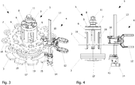
- the gripping and transport device 1 shown differs from the transport device with regard to the hollow cylinder 6 and the cover element 7 Fig. 1 or 2.
- Three window-shaped or rectangular recesses 19 are formed in the hollow cylinder 6, one recess 19 always being arranged between two guide recesses 9. These recesses 19 serve on the one hand to save material and weight and on the other hand as access to the interior of the hollow cylinder 6 in order to clean the hollow cylinder 6 and / or any components within the hollow cylinder more easily and quickly.
- corresponding, in particular insertable elements of the setting plate 2, such as pins, bolts or the like can be in operative engagement with the recess 19 or protrude into it in order to form an additional guide and / or height adjustment limit.
- the cover element 7 also has recesses in the shape of an arch in order to enable material and weight savings.
- Fig. 4 the gripping and transport device 1 is off Fig. 3 shown in side view. It can be seen here that the lower edge of the guide recesses 9 and the recess or recess 19 of the hollow cylinder 6 are at the same height.
Priority Applications (4)
| Application Number | Priority Date | Filing Date | Title |
|---|---|---|---|
| EP20175408.2A EP3912936A1 (fr) | 2020-05-19 | 2020-05-19 | Dispositif de guidage ainsi que dispositif de préhension et de transport permettant d'appréhender, de maintenir, de guider et de transporter des récipients de type bouteille |
| US17/234,210 US11427411B2 (en) | 2020-05-19 | 2021-04-19 | Guiding device as well as gripping and transport device for gripping, holding, guiding and transporting bottle-like containers |
| CN202110459304.4A CN113682800A (zh) | 2020-05-19 | 2021-04-27 | 用于夹持、保持、引导和输送瓶状容器的引导装置以及夹持和输送装置 |
| JP2021083573A JP2021181379A (ja) | 2020-05-19 | 2021-05-18 | 案内装置、ならびにボトル状容器を把持、保持、案内、および搬送するための把持搬送装置 |
Applications Claiming Priority (1)
| Application Number | Priority Date | Filing Date | Title |
|---|---|---|---|
| EP20175408.2A EP3912936A1 (fr) | 2020-05-19 | 2020-05-19 | Dispositif de guidage ainsi que dispositif de préhension et de transport permettant d'appréhender, de maintenir, de guider et de transporter des récipients de type bouteille |
Publications (1)
| Publication Number | Publication Date |
|---|---|
| EP3912936A1 true EP3912936A1 (fr) | 2021-11-24 |
Family
ID=70779481
Family Applications (1)
| Application Number | Title | Priority Date | Filing Date |
|---|---|---|---|
| EP20175408.2A Pending EP3912936A1 (fr) | 2020-05-19 | 2020-05-19 | Dispositif de guidage ainsi que dispositif de préhension et de transport permettant d'appréhender, de maintenir, de guider et de transporter des récipients de type bouteille |
Country Status (4)
| Country | Link |
|---|---|
| US (1) | US11427411B2 (fr) |
| EP (1) | EP3912936A1 (fr) |
| JP (1) | JP2021181379A (fr) |
| CN (1) | CN113682800A (fr) |
Citations (7)
| Publication number | Priority date | Publication date | Assignee | Title |
|---|---|---|---|---|
| JPH02117515A (ja) * | 1988-10-26 | 1990-05-02 | Shibuya Kogyo Co Ltd | クランプ式物品搬送装置 |
| EP2093169A1 (fr) * | 2008-02-23 | 2009-08-26 | Krones AG | Transporteur de type roue étoilée |
| CN103867675A (zh) * | 2012-12-18 | 2014-06-18 | 上银科技股份有限公司 | 一种晶圆搬运机器人 |
| CN106523634A (zh) * | 2016-12-07 | 2017-03-22 | 上海宇航系统工程研究所 | 一种多级空心丝杠传动的双向伸缩机械臂 |
| EP3239078A1 (fr) * | 2016-04-28 | 2017-11-01 | Tyrolon-Schulnig GmbH | Dispositif de reglage en hauteur pour un dispositif de prehension et de transport destine a saisir, retenir, guide et transporter des recipients en forme de bouteille |
| CN207390894U (zh) * | 2017-09-15 | 2018-05-22 | 河南中烟工业有限责任公司 | 一种振动输送机偏心总成顶起装置 |
| CN106348197B (zh) * | 2016-09-23 | 2018-08-14 | 天津理工大学 | 用于重物的快速升降装置 |
Family Cites Families (15)
| Publication number | Priority date | Publication date | Assignee | Title |
|---|---|---|---|---|
| US5826400A (en) * | 1996-08-21 | 1998-10-27 | Anderson-Martin Machine Company | Plastic bottle rotation restraint for capping machine |
| FR2805252B1 (fr) * | 2000-02-21 | 2002-06-28 | Sidel Sa | Dispositif de transfert de recipients comportant une roue de guidage a geometrie variable |
| US6581751B1 (en) * | 2000-10-04 | 2003-06-24 | Owens-Brockway Glass Container Inc. | Method and apparatus for inspecting articles of glassware |
| ITBO20030433A1 (it) * | 2003-07-17 | 2005-01-18 | Azionaria Costruzioni Acma Spa | Convogliatore rotante. |
| US8813950B2 (en) * | 2010-05-07 | 2014-08-26 | The Procter & Gamble Company | Automated adjustment system for star wheel |
| FR2961498B1 (fr) * | 2010-06-17 | 2012-07-13 | Sidel Participations | Dispositif de transport de corps creux equipe de moyens de detection de rupture d'une couche de contact entre un suiveur de came et une came |
| EP2481692B1 (fr) * | 2011-01-29 | 2013-08-21 | Tetra Laval Holdings & Finance S.A. | Unité pour le transfert et le basculement d'emballages scellés de produits alimentaires pouvant être versés |
| DE102013104082B4 (de) * | 2013-04-23 | 2017-02-02 | Khs Gmbh | Transportvorrichtung für Behälter |
| DE102013218337A1 (de) * | 2013-09-12 | 2015-03-12 | Krones Aktiengesellschaft | Transporteinrichtung und Verfahren zum Transport von Kunststoffbehältnissen oder Vorformlingen |
| DE102013113292A1 (de) * | 2013-12-02 | 2015-06-18 | Khs Gmbh | Transportstern mit verstellbaren Sterntaschen |
| MX2016014840A (es) * | 2014-05-20 | 2017-05-30 | Gea Food Solutions Weert Bv | Rueda de transferencia entre una unidad de formado de paletas y una unidad de envoltura de paletas. |
| US9181043B1 (en) * | 2014-06-03 | 2015-11-10 | The Procter & Gamble Company | Elevation change system for a rotary device |
| US9302856B2 (en) * | 2014-06-03 | 2016-04-05 | The Procter & Gamble Company | Method for adjusting a rotary device |
| DE102017105015B4 (de) * | 2017-03-09 | 2019-10-10 | Tyrolon-Schulnig Gmbh | Greif- und Transportvorrichtung |
| US10399795B1 (en) * | 2019-03-22 | 2019-09-03 | Ykmc, Inc. | Transfer apparatus using star wheel |
-
2020
- 2020-05-19 EP EP20175408.2A patent/EP3912936A1/fr active Pending
-
2021
- 2021-04-19 US US17/234,210 patent/US11427411B2/en active Active
- 2021-04-27 CN CN202110459304.4A patent/CN113682800A/zh active Pending
- 2021-05-18 JP JP2021083573A patent/JP2021181379A/ja active Pending
Patent Citations (7)
| Publication number | Priority date | Publication date | Assignee | Title |
|---|---|---|---|---|
| JPH02117515A (ja) * | 1988-10-26 | 1990-05-02 | Shibuya Kogyo Co Ltd | クランプ式物品搬送装置 |
| EP2093169A1 (fr) * | 2008-02-23 | 2009-08-26 | Krones AG | Transporteur de type roue étoilée |
| CN103867675A (zh) * | 2012-12-18 | 2014-06-18 | 上银科技股份有限公司 | 一种晶圆搬运机器人 |
| EP3239078A1 (fr) * | 2016-04-28 | 2017-11-01 | Tyrolon-Schulnig GmbH | Dispositif de reglage en hauteur pour un dispositif de prehension et de transport destine a saisir, retenir, guide et transporter des recipients en forme de bouteille |
| CN106348197B (zh) * | 2016-09-23 | 2018-08-14 | 天津理工大学 | 用于重物的快速升降装置 |
| CN106523634A (zh) * | 2016-12-07 | 2017-03-22 | 上海宇航系统工程研究所 | 一种多级空心丝杠传动的双向伸缩机械臂 |
| CN207390894U (zh) * | 2017-09-15 | 2018-05-22 | 河南中烟工业有限责任公司 | 一种振动输送机偏心总成顶起装置 |
Also Published As
| Publication number | Publication date |
|---|---|
| CN113682800A (zh) | 2021-11-23 |
| US11427411B2 (en) | 2022-08-30 |
| JP2021181379A (ja) | 2021-11-25 |
| US20210362959A1 (en) | 2021-11-25 |
Similar Documents
| Publication | Publication Date | Title |
|---|---|---|
| DE102017105015B4 (de) | Greif- und Transportvorrichtung | |
| DE2636690C2 (fr) | ||
| DE102017105016B3 (de) | Lagervorrichtung | |
| WO2004099042A1 (fr) | Section de transporteur pourvue d'un rail ajustable, et mecanisme d'actionnement | |
| EP2155598A2 (fr) | Tête de vissage à fixation rapide | |
| DE60108546T2 (de) | Vorrichtung für Maschinen zum Umordnen von Behältern, mit automatischen Mitteln zum Ausrichten und Abwerfen eines empfangenen Behälters | |
| EP2736834B1 (fr) | Dispositif pour la fermeture de récipients | |
| WO2018041428A1 (fr) | Conduit de capsules segmenté, à réglabe télescopique | |
| EP3912936A1 (fr) | Dispositif de guidage ainsi que dispositif de préhension et de transport permettant d'appréhender, de maintenir, de guider et de transporter des récipients de type bouteille | |
| EP3816076A1 (fr) | Dispositif d'appréhension ainsi que dispositif de transport permettant d'appréhender, de maintenir et de guider, en particulier des récipients de type bouteille | |
| DE4111475C2 (de) | Rohrpostbüchse | |
| DE102015114567B4 (de) | Einsetzbare Ansteuerungsvorrichtung und Transportvorrichtung für Behälter, sowie schwebend positionierte Ansteuerungsvorrichtung | |
| DE4314696C2 (de) | Magazinvorrichtung für Faltschachteln bei Verpackungsmaschinen mit verstellbarem Magazinschacht | |
| EP1321366B1 (fr) | Dispositif d'orientation en rotation de bouteilles avec fermeture à étrier | |
| DE3135609C2 (de) | Bürotisch | |
| DE1940287A1 (de) | Automatische Abfuell- und Verschliessmaschine | |
| DE4414450C1 (de) | Niederhaltevorrichtung | |
| DE1101238B (de) | Fadenbremse fuer Zwirnspindeln, insbesondere fuer Doppeldraht-Zwirnspindeln | |
| WO2024028228A1 (fr) | Chariot de transport pour le transport de récipients dans une installation de remplissage et/ou d'emballage | |
| EP3114914A1 (fr) | Dispositif de couplage mecanique | |
| DE1860454U (de) | Stanze fuer lochkarten, insbesondere flaechenlochkarten. | |
| DE3814914A1 (de) | Verpackung mit oeffnungen zu deren handhabung sowie vorrichtung zum handhaben von derartigen verpackungen | |
| DE2641942C (de) | Verschlußvorrichtung für Wägebehälter | |
| DE3336232A1 (de) | Automatische werkzeugwechsel-einrichtung fuer werkzeug-maschinen | |
| DE102011108429A1 (de) | Vorrichtung zum Verschließen von Behältern |
Legal Events
| Date | Code | Title | Description |
|---|---|---|---|
| PUAI | Public reference made under article 153(3) epc to a published international application that has entered the european phase |
Free format text: ORIGINAL CODE: 0009012 |
|
| STAA | Information on the status of an ep patent application or granted ep patent |
Free format text: STATUS: REQUEST FOR EXAMINATION WAS MADE |
|
| 17P | Request for examination filed |
Effective date: 20210506 |
|
| AK | Designated contracting states |
Kind code of ref document: A1 Designated state(s): AL AT BE BG CH CY CZ DE DK EE ES FI FR GB GR HR HU IE IS IT LI LT LU LV MC MK MT NL NO PL PT RO RS SE SI SK SM TR |
|
| B565 | Issuance of search results under rule 164(2) epc |
Effective date: 20201106 |
|
| STAA | Information on the status of an ep patent application or granted ep patent |
Free format text: STATUS: EXAMINATION IS IN PROGRESS |
|
| 17Q | First examination report despatched |
Effective date: 20230228 |