EP3911535B1 - Höhenverstellbare sitzvorrichtung - Google Patents
Höhenverstellbare sitzvorrichtung Download PDFInfo
- Publication number
- EP3911535B1 EP3911535B1 EP20700584.4A EP20700584A EP3911535B1 EP 3911535 B1 EP3911535 B1 EP 3911535B1 EP 20700584 A EP20700584 A EP 20700584A EP 3911535 B1 EP3911535 B1 EP 3911535B1
- Authority
- EP
- European Patent Office
- Prior art keywords
- seat
- seat portion
- pivot
- support arm
- diagonal support
- Prior art date
- Legal status (The legal status is an assumption and is not a legal conclusion. Google has not performed a legal analysis and makes no representation as to the accuracy of the status listed.)
- Active
Links
Images

Classifications
-
- B—PERFORMING OPERATIONS; TRANSPORTING
- B60—VEHICLES IN GENERAL
- B60N—SEATS SPECIALLY ADAPTED FOR VEHICLES; VEHICLE PASSENGER ACCOMMODATION NOT OTHERWISE PROVIDED FOR
- B60N2/00—Seats specially adapted for vehicles; Arrangement or mounting of seats in vehicles
- B60N2/24—Seats specially adapted for vehicles; Arrangement or mounting of seats in vehicles for particular purposes or particular vehicles
- B60N2/30—Non-dismountable or dismountable seats storable in a non-use position, e.g. foldable spare seats
- B60N2/3038—Cushion movements
- B60N2/3063—Cushion movements by composed movement
- B60N2/3065—Cushion movements by composed movement in a longitudinal-vertical plane
-
- B—PERFORMING OPERATIONS; TRANSPORTING
- B60—VEHICLES IN GENERAL
- B60N—SEATS SPECIALLY ADAPTED FOR VEHICLES; VEHICLE PASSENGER ACCOMMODATION NOT OTHERWISE PROVIDED FOR
- B60N2/00—Seats specially adapted for vehicles; Arrangement or mounting of seats in vehicles
- B60N2/24—Seats specially adapted for vehicles; Arrangement or mounting of seats in vehicles for particular purposes or particular vehicles
- B60N2/30—Non-dismountable or dismountable seats storable in a non-use position, e.g. foldable spare seats
- B60N2/3081—Seats convertible into parts of the seat cushion or the back-rest or disapppearing therein, e.g. for children
- B60N2/3086—Disappearing in a recess of the cushion
-
- B—PERFORMING OPERATIONS; TRANSPORTING
- B60—VEHICLES IN GENERAL
- B60N—SEATS SPECIALLY ADAPTED FOR VEHICLES; VEHICLE PASSENGER ACCOMMODATION NOT OTHERWISE PROVIDED FOR
- B60N2/00—Seats specially adapted for vehicles; Arrangement or mounting of seats in vehicles
- B60N2/24—Seats specially adapted for vehicles; Arrangement or mounting of seats in vehicles for particular purposes or particular vehicles
- B60N2/30—Non-dismountable or dismountable seats storable in a non-use position, e.g. foldable spare seats
- B60N2/3088—Non-dismountable or dismountable seats storable in a non-use position, e.g. foldable spare seats characterised by the mechanical link
- B60N2/309—Non-dismountable or dismountable seats storable in a non-use position, e.g. foldable spare seats characterised by the mechanical link rods
-
- B—PERFORMING OPERATIONS; TRANSPORTING
- B60—VEHICLES IN GENERAL
- B60N—SEATS SPECIALLY ADAPTED FOR VEHICLES; VEHICLE PASSENGER ACCOMMODATION NOT OTHERWISE PROVIDED FOR
- B60N2/00—Seats specially adapted for vehicles; Arrangement or mounting of seats in vehicles
- B60N2/24—Seats specially adapted for vehicles; Arrangement or mounting of seats in vehicles for particular purposes or particular vehicles
- B60N2/42—Seats specially adapted for vehicles; Arrangement or mounting of seats in vehicles for particular purposes or particular vehicles the seat constructed to protect the occupant from the effect of abnormal g-forces, e.g. crash or safety seats
- B60N2/43—Safety locks
Definitions
- the present invention relates to a seating device and in particular a seating device intended to allow the height adjustment of a seat portion.
- the present invention proposes an adjustable seating device intended to be integrated into a vehicle seat or bench, to make it possible to raise a portion of the vehicle seat to install children and belt them safely.
- the document WO2015167378 discloses a height-adjustable seating device, comprising in particular an articulation system with a deformable parallelogram and a diagonal reinforcing support, but this structure can be complex to manufacture, and can present disadvantages during use, with slippage between the diagonal reinforcement support and the articulation arms of the deformable parallelogram which can generate wear, noise, or blockages.
- the document DE 19522967 A1 discloses a child seat integrated into a vehicle seat.
- the document FR2706381A1 discloses an integrable child seat for a vehicle seat.
- An aim of the present invention is to respond to the drawbacks of the prior art mentioned above and in particular, first of all, to propose an adjustable seating device which is simple to manufacture, and which is easy to use and reliable.
- the device according to the implementation above comprises a diagonal support arm whose length varies.
- the diagonal support arm is extensible, and designed to vary in length during the movement of the seat portion relative to the base portion. Consequently, the two ends of the diagonal support arm can remain constantly attached to the deformable parallelogram during deployment or retraction, which simplifies the system, the kinematics and avoids providing sliding tracks for one end of the support arm.
- diagonal on an articulation arm of the deformable parallelogram is whose length varies.
- a deformable parallelogram typically comprises four bars and forms a system composed of four rigid bodies, generally articulated together by rotating connections: ball joints or pivots.
- the parts are bars, the connections being at the ends of the bars; one of the bars can be connected to the chassis of the vehicle or to its seat, and then forms the base portion; one of the other bars (opposite the base portion) is then movable in a circular translational movement relative to the base portion.
- the diagonal support arm is arranged to provide a mechanical stop to the seat portion, when the seat portion is in the second position.
- a stop integrated into the diagonal support arm simplifies the general design of the device.
- the first blocking means are engaged during normal use, and there is then a play or a space within the second blocking means, so that the system is not hyperstatic. Manufacturing is simplified. However, in the event of a vehicle impact, the deceleration imposed on the vehicle and the occupants can generate a second (significant) effort on the system.
- the first blocking means are designed to deform so as to take up the clearance or internal space of the second blocking means which have a greater resistance capacity once engaged, to resist the second effort.
- the diagonal support arm comprises a sliding connection of the first part relative to the second part.
- the second part is mounted in pivot connection relative to the seat portion, and the first part is mounted in pivot connection relative to the base portion.
- the first part and/or the second part is (are) formed from a sheet of stamped sheet metal.
- the slide connection is then obtained by folding two portions of sheet metal into a U, on each side of one of the two parts.
- the adjustable seating device comprises at least one elastic return element, and at least two distinct pivot joints of the deformable parallelogram each comprise a portion of said at least one elastic return element.
- said at least one elastic return element is formed by an elastic wire comprising at least two rectilinear portions, each rectilinear portion forming a hinge axis for each of the two distinct pivot joints.
- each rectilinear portion acts like a torsion bar and a comb can be provided at the end of each part linked to the joint, with bores to receive the rectilinear portions.
- the assembly and manufacturing of the parts is easy.
- said at least one elastic return element comprises at least one plastically deformed end, so as to make the elastic return element unremovable from the pivot joints. Indeed, at the end of assembly, a folding operation (permanent deformation) makes the system undismountable, which ensures good safety of use.
- said at least one elastic return element has a general U shape, with its ends folded, so as to make the elastic return element unremovable from the pivot joints.
- said at least one elastic return element presents a tensioning so as to impose on the seat portion a position of balance, arranged between the retracted position and the deployed position.
- the equilibrium position is provided between the retracted position and the deployed position, the passage into each of these retracted or deployed positions causes a tensioning which makes it possible to limit clicking noises.
- This also makes the system easier to use, with an automatic start of movement from one of the retracted or deployed positions to the balance position.
- the adjustable seating device comprises a control handle. It is of course possible to provide a locking system in the retracted position controlled by the handle.
- a locking bolt directly integrated into the handle which is mounted on the seat portion, and a striker in the base portion (or vice versa), so that the bolt can engage in the striker, when the seat portion is in the retracted position.
- a second aspect of the invention relates to a vehicle seat base, preferably for a seat of row two or higher, comprising at least one adjustable seat device according to the first aspect of the invention.
- a third aspect of the invention relates to a motor vehicle comprising at least one adjustable seating device according to the first aspect of the invention.
- the assembly method comprises a step consisting of hooking the folded end to one of the parts linked to the pivot joint.
- the assembly method comprises a step consisting of tensioning the elastic return element, before hooking the folded end to one of the parts linked to the pivot joint.
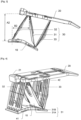
- the adjustable seat device comprises in particular a base portion 10, a seat portion 20, and an articulation system 30.
- THE figures 1 to 3 represent the adjustable seating device without its trim, that is to say that only the frame or structural parts are shown.
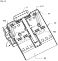
- the adjustable seating device is intended to be integrated into a vehicle seat, with the seat portion 20 in the retracted position ( figure 1 ) arranged flush or at the same level as the rest of the vehicle seat, and the seat portion 20 in the deployed position ( figure 3 or figure 4 Or figure 7 ) arranged above the rest of the vehicle seat, to allow a small child to be properly belted, which avoids the need for a separate booster seat.
- FIG. 1 represents the seating device with the seating portion 20 in a retracted position, that is to say with the seating portion 20 folded against the base portion 10.
- the seating portion 20 and the trim (not shown) of the seat portion 20 can be located at the same level as the rest of the seat of the vehicle. An adult can sit comfortably.
- FIG. 3 represents the seating device with the seating portion 20 in an deployed position, that is to say with the seating portion 20 raised relative to the base portion 10.
- the seating portion 20 and the trim (not shown) of the seat portion 20 are well above the rest of the seat of the vehicle, so that a small child can be belted in complete safety.
- the articulation system 30 also includes a diagonal support arm 31 connected to the upper front pivot 20A of the seat portion 20 and to the lower rear pivot 10B.
- the diagonal support arm 31 has a variable length: in fact, when the seat portion 20 is in the retracted position, the diagonal support arm 31 has a first length and when the seat portion 20 is in the deployed position, the diagonal support arm 31 has a second length.
- This embodiment is preferred because it limits the number of pivot links.
- other embodiments can be provided by connecting the diagonal support arm 31 by independent pivot connections to the first and/or second arm and/or to the base and/or seat portion.
- the diagonal support arm 31 sees its length decrease when it passes from the retracted position to the deployed position.
- the slide portion of the second part 31B is close to the lower rear pivot 10B, which provides good rigidity.
- the diagonal support arm 33 is arranged to provide a mechanical stop to the seat portion 20, when the seat portion 20 is in the second position, called deployed.
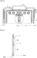
- the first blocking means 34 and the second blocking means 35 are each formed by at least one notch or support zone in the first part 31A and by a protrusion in the second part 31B. Once the protrusions engaged in their respective notches or on their support zones when the seat portion 20 arrives in the deployed position, the blocking means prevent any return to the retracted position.
- first locking means 34 are engaged in normal use (that is to say with a child seated on the seat portion 20), as shown the cut shown Figure 6 , along the VV axis of the figure 5 .
- first blocking means 34 are in contact (c) on the cut, while a clearance (j) is provided at the level of the second blocking means 35.
- this implementation makes it possible to avoid providing tight fits during the manufacture of the first part 31A and the second part 31B, because only the first blocking means 34 are engaged in a normal situation (first effort limited), and a slight deformation of the first blocking means 34 under the second force in the event of a vehicle impact allows the second blocking means 35 to be engaged. Consequently, it is not necessary to provide precise positioning of the first means blocking 34 relative to the second blocking means 35.
- a lever arm provided at the level of the first blocking means 34, is actuated by the handle 21, which makes it possible to release the first blocking means, and the second means blocking, by pivoting the first part 31A relative to the second part 31B, which can then slide relative to each other to let the seat portion 20 go into the retracted position.
- Elastic return means are also provided, with two elastic return elements 41 and 42 provided in the articulation system, to impose a position of balance on the seat portion 20, arranged between the retracted position and the deployed position .
- the elastic return elements 41 and 42 are pre-tensioned to begin to automatically remove the seat portion 20 from the retracted position, and also to begin to automatically fold the seat portion 20 from the retracted position. deployed.
- each elastic return element 41 and 42 comprises at least one rectilinear portion 41C and 42C which forms a hinge axis of the deformable parallelogram.
- the first elastic return element 41 forms the hinge axis at the level of the lower front pivot 10a (between the base portion 10 and the first hinge arm 32) and at the level of the front pivot upper 20A (between the seat portion 20 and the first articulation arm 32).
- the second elastic return element 42 forms the hinge axis at the level of the lower rear pivot 10B (between the base portion 10 and the second hinge arm 33) and at the level of the upper rear pivot 20B (between the base portion 10 and the second hinge arm 33) and at the level of the upper rear pivot 20B (between the base portion 10 seat 20 and the second articulation arm 33).
- each elastic return element comprises ends 41E and 42E which have been plastically deformed (folded), and anchored in the base portion 10 and in the portion of seat 20, after assembly, to make the system unremovable (see the example in dotted lines in the Figure 7 at the bottom left).
Landscapes
- Engineering & Computer Science (AREA)
- Aviation & Aerospace Engineering (AREA)
- Transportation (AREA)
- Mechanical Engineering (AREA)
- Seats For Vehicles (AREA)
Claims (14)
- Verstellbare Sitzvorrichtung für ein Fahrzeug, umfassend:- einen Basisabschnitt (10),- einen Sitzabschnitt (20), der relativ zu dem Basisabschnitt (10) zwischen einer ersten Position, die als eingeklappt bezeichnet wird, und einer zweiten Position, die als ausgeklappt bezeichnet wird, bewegbar ist,- ein Gelenksystem (30), das ein verformbares Parallelogramm ausbildet, mit dem Basisabschnitt (10) und dem Sitzabschnitt (20) verbunden ist und umfassend mindestens einen diagonalen Tragarm (31), der mit dem verformbaren Parallelogramm diagonal verbunden ist, wobei der diagonale Tragarm (31) zum Aufweisen einer ersten Länge, wenn sich der Sitzabschnitt (20) in der ersten Position befindet, und einer zweiten Länge, wenn sich der Sitzabschnitt (20) in der zweiten Position befindet, angeordnet ist, wobei das Gelenksystem (30) umfasst:dadurch gekennzeichnet, dass der diagonale Tragarm (31) mit dem oberen vorderen Drehpunkt (20A) des Sitzabschnitts (20) und mit dem unteren hinteren Drehpunkt (10B) des Basisabschnitts (10) verbunden ist.- einen ersten Gelenkarm (32), der mit einem unteren vorderen Drehpunkt (10A) des Basisabschnitts (10) und mit einem oberen vorderen Drehpunkt (20A) des Sitzabschnitts (20) verbunden ist,- einen zweiten Gelenkarm (33), der mit einem unteren hinteren Drehpunkt (10B) des Basisabschnitts (10) und mit einem oberen hinteren Drehpunkt (20B) des Sitzabschnitts (20) verbunden ist,
- Verstellbare Sitzvorrichtung nach dem vorstehenden Anspruch, wobei der diagonale Tragarm (31) zum Bereitstellen eines mechanischen Anschlags für den Sitzabschnitt (20) angeordnet ist, wenn sich der Sitzabschnitt (20) in der zweiten Position befindet.
- Verstellbare Sitzvorrichtung nach einem der vorstehenden Ansprüche, wobei der diagonale Tragarm (31) umfasst:- erste Blockiermittel (34), die zum Blockieren des diagonalen Tragarms (31) in der zweiten Länge angeordnet sind, wenn sich der Sitzabschnitt (20) in der zweiten Position befindet, und zum Eingreifen und Standhalten einer ersten Kraft angeordnet sind, die als normale Nutzungskraft bezeichnet wird, die auf den Sitzabschnitt (20) ausgeübt wird,- zweite Blockiermittel (35), die zum Blockieren des diagonalen Tragarms (31) in der zweiten Länge angeordnet sind, wenn sich der Sitzabschnitt (20) in der zweiten Position befindet, und zum Eingreifen und Standhalten einer zweiten Kraft angeordnet sind, die als Fahrzeugaufprallkraft bezeichnet wird und größer als die erste Kraft ist, die auf den Sitzabschnitt (20) ausgeübt wird,wobei die zweiten Blockiermittel (35) nur dann in Eingriff sind, wenn die zweite Kraft auf den Sitzabschnitt ausgeübt wird.
- Verstellbare Sitzvorrichtung nach einem der vorstehenden Ansprüche, wobei der diagonale Tragarm (31) umfasst:- ein erstes Stück (31A) und- ein zweites Stück (31B), das relativ zu dem ersten Stück (31A) bewegbar ist.
- Verstellbare Sitzvorrichtung nach dem vorstehenden Anspruch, wobei das zweite Stück (31B) relativ zu dem ersten Stück (31A) bewegbar ist:- gemäß einer Translation während eines ersten Teils der Bewegung des Sitzabschnitts (20) von der eingeklappten Position in die ausgeklappte Position,- gemäß mindestens einer Verriegelungsrotation während eines zweiten Teils der Bewegung des Sitzabschnitts (20) von der eingeklappten Position in die ausgeklappte Position.
- Verstellbare Sitzvorrichtung nach einem der Ansprüche 4 bis 5, wobei das zweite Stück (31B) relativ zu dem Sitzabschnitt (20) in Drehverbindung angebracht ist, und wobei das erste Stück (31A) relativ zu dem Basisabschnitt (10) in Drehverbindung angebracht ist.
- Verstellbare Sitzvorrichtung nach einem der vorstehenden Ansprüche, umfassend mindestens ein elastisches Rückstellelement (41, 42), und wobei mindestens zwei getrennte Drehgelenke des verformbaren Parallelogramms jeweils einen Abschnitt des mindestens einen elastischen Rückstellelements (41, 42) umfassen.
- Verstellbare Sitzvorrichtung nach dem vorstehenden Anspruch, wobei das mindestens eine elastische Rückstellelement (41, 42) durch einen elastischen Faden ausgebildet ist, umfassend mindestens zwei geradlinige Abschnitte (41C, 42C), wobei jeder geradlinige Abschnitt (41C, 42C) eine Scharnierachse für jedes der zwei getrennten Drehgelenke ausbildet.
- Verstellbare Sitzvorrichtung nach einem der Ansprüche 7 bis 8, wobei das mindestens eine elastische Rückstellelement (41, 42) eine Spannung aufweist, um dem Sitzabschnitt (20) eine Gleichgewichtsposition aufzuzwingen, die zwischen der eingeklappten Position und der ausgeklappten Position angeordnet ist.
- Sitzteil, vorzugsweise für einen Sitz einer zweiten Sitzreihe oder höher, umfassend mindestens eine verstellbare Sitzvorrichtung nach einem der vorstehenden Ansprüche.
- Kraftfahrzeug, umfassend ein mindestens eine verstellbare Sitzvorrichtung nach einem der Ansprüche 1 bis 9.
- Verfahren zum Zusammenbauen einer verstellbaren Sitzvorrichtung nach einem der Ansprüche 1 bis 9, umfassend mindestens eine Phase des Zusammenbaus eines Drehgelenks des verformbaren Parallelogramms, umfassend die folgenden Schritte:- Einfügen eines geraden Abschnitts (41C, 42C) eines elastischen Rückstellelements, der eine Scharnierachse ausbildet, in mindestens einen weiblichen Abschnitt jedes der Stücke, die mit dem Drehgelenk verbunden sind, so dass ein Scharnier ausgebildet wird,- plastisches Verformen eines freien Endes (41E, 42E) des geraden Abschnitts (41C, 42C) um das elastische Rückstellelement des ausgebildeten Scharniers unzerlegbar zu machen.
- Montageverfahren nach dem vorstehenden Anspruch, umfassend einen Schritt bestehend aus einem Festmachen des gebogenen Endes (41E, 42E) an einem der Stücke, die mit dem Drehgelenk verbunden sind.
- Montageverfahren nach dem vorstehenden Anspruch, umfassend einen Schritt bestehend aus einem Spannen des elastischen Rückstellelements, vor dem Festmachen des gebogenen Endes an einem der Stücke, die mit dem Drehgelenk verbunden sind.
Applications Claiming Priority (2)
| Application Number | Priority Date | Filing Date | Title |
|---|---|---|---|
| FR1900320A FR3091678B1 (fr) | 2019-01-14 | 2019-01-14 | Dispositif d'assise réglable en hauteur |
| PCT/EP2020/050665 WO2020148220A1 (fr) | 2019-01-14 | 2020-01-13 | Dispositif d'assise reglable en hauteur |
Publications (2)
| Publication Number | Publication Date |
|---|---|
| EP3911535A1 EP3911535A1 (de) | 2021-11-24 |
| EP3911535B1 true EP3911535B1 (de) | 2024-05-15 |
Family
ID=67742496
Family Applications (1)
| Application Number | Title | Priority Date | Filing Date |
|---|---|---|---|
| EP20700584.4A Active EP3911535B1 (de) | 2019-01-14 | 2020-01-13 | Höhenverstellbare sitzvorrichtung |
Country Status (7)
| Country | Link |
|---|---|
| US (1) | US11697363B2 (de) |
| EP (1) | EP3911535B1 (de) |
| JP (1) | JP7519362B2 (de) |
| KR (1) | KR102837476B1 (de) |
| CN (1) | CN113286725B (de) |
| FR (1) | FR3091678B1 (de) |
| WO (1) | WO2020148220A1 (de) |
Family Cites Families (26)
| Publication number | Priority date | Publication date | Assignee | Title |
|---|---|---|---|---|
| JPS57182530U (de) * | 1981-05-15 | 1982-11-19 | ||
| EP0245650B1 (de) * | 1986-04-14 | 1993-07-21 | P.A. Rentrop, Hubbert & Wagner Fahrzeugausstattungen GmbH & Co. KG | Rückhalteeinrichtung in Fahrzeugen |
| JP2520005B2 (ja) * | 1989-02-23 | 1996-07-31 | 小糸工業株式会社 | 衝撃エネルギ―を吸収する座席の脚構造 |
| US5104182A (en) * | 1991-08-12 | 1992-04-14 | The Berkline Corporation | Convertible sofa |
| GB2278775B (en) * | 1993-06-11 | 1997-08-13 | Hammerstein Gmbh C Rob | Child seat capable of being integrated into a motor-vehicle seat |
| DE19522967B4 (de) * | 1994-07-04 | 2004-11-18 | C. Rob. Hammerstein Gmbh & Co. Kg | Integrierbarer Kindersitz für einen Kraftfahrzeugsitz |
| US5657950A (en) * | 1995-08-14 | 1997-08-19 | Industrial Technology Research Intitute | Backward-leaning-movement seat leg structure |
| DE19839673C1 (de) * | 1998-09-01 | 1999-09-02 | Grammer Ag | Integrierter Kindersitz für einen Kraftfahrzeugsitz |
| US6106066A (en) * | 1999-08-30 | 2000-08-22 | Freedman Seating Company | Stowable cantilevered seat |
| DE10130813C2 (de) * | 2001-06-26 | 2003-06-05 | Keiper Gmbh & Co Kg | Fahrzeugsitz mit Bodenstellung |
| DE10306827B4 (de) * | 2003-02-19 | 2005-03-10 | Keiper Gmbh & Co Kg | Höheneinstellbarer Fahrzeugsitz mit Crashsperreneinheit |
| DE10355819B4 (de) * | 2003-11-28 | 2008-08-21 | Keiper Gmbh & Co.Kg | Fahrzeugsitz, insbesondere Kraftfahrzeugsitz |
| CN2687817Y (zh) * | 2004-03-26 | 2005-03-23 | 杨家明 | 新颖电器开关 |
| DE102004053035A1 (de) * | 2004-11-03 | 2006-05-04 | Daimlerchrysler Ag | Verlagerungseinrichtung eines Personensitzes, insbesondere in einem Fahrerhaus eines Nutzfahrzeuges |
| DE102006001591B3 (de) * | 2006-01-11 | 2007-07-19 | Johnson Controls Gmbh | Einstellbar vorgesehener Fahrzeugsitz mit beweglichem Lehnenteil und Verfahren zur Höhenverstellung des Fahrzeugsitzes |
| US8066327B2 (en) * | 2006-08-22 | 2011-11-29 | Grand Rapids Controls Company Llc | Control mechanism |
| JP5176313B2 (ja) | 2006-12-08 | 2013-04-03 | 日産自動車株式会社 | 車両用シート |
| US8573686B2 (en) * | 2010-01-21 | 2013-11-05 | Bae Industries, Inc. | Scissor retractable headrest |
| EP2760700B1 (de) * | 2011-09-27 | 2016-11-02 | Mobius Protection Systems Ltd. | Sicherheitssitz |
| CN203211127U (zh) * | 2013-02-22 | 2013-09-25 | 浙江吉利汽车研究院有限公司杭州分公司 | 一种汽车座椅结构 |
| WO2015153734A1 (en) * | 2014-04-02 | 2015-10-08 | B/E Aerospace, Inc. | Cradle recline mechanism for fixed-shell aircraft seat |
| CN106458062A (zh) * | 2014-04-30 | 2017-02-22 | 奥托立夫开发公司 | 集成式儿童座椅框架 |
| DE102015110705A1 (de) * | 2014-07-02 | 2016-01-07 | Recaro Aircraft Seating Gmbh & Co. Kg | Flugzeugsitzvorrichtung |
| DE102018110683B4 (de) * | 2017-12-21 | 2020-08-27 | Adient Engineering and IP GmbH | Crashsperreneinheit, insbesondere für einen fahrzeugsitz, sowie fahrzeugsitz |
| US10549670B1 (en) * | 2018-09-26 | 2020-02-04 | Faurecia Automotive Seating, Llc | Seat locking system |
| DE102021111783A1 (de) * | 2021-05-06 | 2022-11-10 | Faurecia Autositze Gmbh | Fahrzeugsitz-Crashsicherungseinrichtung und Fahrzeugsitz |
-
2019
- 2019-01-14 FR FR1900320A patent/FR3091678B1/fr active Active
-
2020
- 2020-01-13 US US17/310,025 patent/US11697363B2/en active Active
- 2020-01-13 KR KR1020217025157A patent/KR102837476B1/ko active Active
- 2020-01-13 CN CN202080008954.0A patent/CN113286725B/zh active Active
- 2020-01-13 WO PCT/EP2020/050665 patent/WO2020148220A1/fr not_active Ceased
- 2020-01-13 EP EP20700584.4A patent/EP3911535B1/de active Active
- 2020-01-13 JP JP2021540871A patent/JP7519362B2/ja active Active
Also Published As
| Publication number | Publication date |
|---|---|
| US11697363B2 (en) | 2023-07-11 |
| WO2020148220A1 (fr) | 2020-07-23 |
| EP3911535A1 (de) | 2021-11-24 |
| KR20210113316A (ko) | 2021-09-15 |
| JP2022518214A (ja) | 2022-03-14 |
| CN113286725B (zh) | 2023-07-25 |
| CN113286725A (zh) | 2021-08-20 |
| JP7519362B2 (ja) | 2024-07-19 |
| FR3091678A1 (fr) | 2020-07-17 |
| KR102837476B1 (ko) | 2025-07-24 |
| FR3091678B1 (fr) | 2022-06-17 |
| US20220118892A1 (en) | 2022-04-21 |
Similar Documents
| Publication | Publication Date | Title |
|---|---|---|
| EP4029730B1 (de) | Rückenlehne eines fahrzeugsitzes | |
| FR2969057A1 (fr) | Siege escamotable pour un vehicule automobile | |
| EP0718147A1 (de) | Sitzrahmen für Fahrzeugsitze | |
| EP3911535B1 (de) | Höhenverstellbare sitzvorrichtung | |
| EP3597478B1 (de) | Sitz, der ein ausziehbares brettchen umfasst | |
| WO2017118667A1 (fr) | Nacelle et embase pour transport d'un enfant dans un véhicule | |
| CA2503091A1 (fr) | Flasque pour structure rigide d'un siege en vehicule, siege de vehicule comprenant un tel flasque et procede de fabrication d'un tel flasque | |
| FR3021001A1 (fr) | Vehicule automobile comportant des supports de siege retractables | |
| EP2018293A1 (de) | Verstaubarer sitz, insbesondere für die dritte sitzreihe | |
| EP0373081B1 (de) | Klappbarer Sitz, insbesondere für die Ausrüstung von Kraftfahrzeugen | |
| FR2917024A1 (fr) | Siege escamotable notamment pour vehicule automobile | |
| EP1481839B1 (de) | Kraftfahrzeug mit einer neigbaren hinteren Sitzbank. | |
| EP2868519B1 (de) | Versenkbarer Sitz mit Kippsicherung | |
| FR3109561A1 (fr) | Siège de véhicule | |
| EP3532341B1 (de) | Modularer sitz für ein kraftfahrzeug | |
| EP1707431A2 (de) | Bedienungsvorrichtung eines Fahrzeugsitzes | |
| FR2923762A1 (fr) | Equipement articule pour siege de vehicule automobile, en particulier accoudoir | |
| FR3071201A1 (fr) | Accoudoir de pilier central | |
| FR3156084A1 (fr) | Dossier de siège de véhicule | |
| FR3160656A1 (fr) | Dispositif d’accrochage de boucle de ceinture de sécurité | |
| EP2147819B1 (de) | Verstaubarer Sitz für einen Kraftfahrzeug | |
| EP1225084B1 (de) | Sitz mit veränderlicher Form | |
| WO2016030639A1 (fr) | Siège pour véhicule comprenant un plancher de chargement | |
| FR3156082A1 (fr) | Dossier de siège de véhicule | |
| EP1928690A1 (de) | Hubunterstützungsvorrichtung für einen kraftfahrzeugsitz zum bringen des sitzes in eine klappmesserposition |
Legal Events
| Date | Code | Title | Description |
|---|---|---|---|
| STAA | Information on the status of an ep patent application or granted ep patent |
Free format text: STATUS: UNKNOWN |
|
| STAA | Information on the status of an ep patent application or granted ep patent |
Free format text: STATUS: THE INTERNATIONAL PUBLICATION HAS BEEN MADE |
|
| PUAI | Public reference made under article 153(3) epc to a published international application that has entered the european phase |
Free format text: ORIGINAL CODE: 0009012 |
|
| STAA | Information on the status of an ep patent application or granted ep patent |
Free format text: STATUS: REQUEST FOR EXAMINATION WAS MADE |
|
| 17P | Request for examination filed |
Effective date: 20210806 |
|
| AK | Designated contracting states |
Kind code of ref document: A1 Designated state(s): AL AT BE BG CH CY CZ DE DK EE ES FI FR GB GR HR HU IE IS IT LI LT LU LV MC MK MT NL NO PL PT RO RS SE SI SK SM TR |
|
| DAV | Request for validation of the european patent (deleted) | ||
| DAX | Request for extension of the european patent (deleted) | ||
| GRAP | Despatch of communication of intention to grant a patent |
Free format text: ORIGINAL CODE: EPIDOSNIGR1 |
|
| STAA | Information on the status of an ep patent application or granted ep patent |
Free format text: STATUS: GRANT OF PATENT IS INTENDED |
|
| INTG | Intention to grant announced |
Effective date: 20231214 |
|
| GRAS | Grant fee paid |
Free format text: ORIGINAL CODE: EPIDOSNIGR3 |
|
| GRAA | (expected) grant |
Free format text: ORIGINAL CODE: 0009210 |
|
| STAA | Information on the status of an ep patent application or granted ep patent |
Free format text: STATUS: THE PATENT HAS BEEN GRANTED |
|
| AK | Designated contracting states |
Kind code of ref document: B1 Designated state(s): AL AT BE BG CH CY CZ DE DK EE ES FI FR GB GR HR HU IE IS IT LI LT LU LV MC MK MT NL NO PL PT RO RS SE SI SK SM TR |
|
| REG | Reference to a national code |
Ref country code: CH Ref legal event code: EP |
|
| REG | Reference to a national code |
Ref country code: DE Ref legal event code: R096 Ref document number: 602020030894 Country of ref document: DE |
|
| REG | Reference to a national code |
Ref country code: IE Ref legal event code: FG4D Free format text: LANGUAGE OF EP DOCUMENT: FRENCH |
|
| REG | Reference to a national code |
Ref country code: LT Ref legal event code: MG9D |
|
| REG | Reference to a national code |
Ref country code: NL Ref legal event code: MP Effective date: 20240515 |
|
| PG25 | Lapsed in a contracting state [announced via postgrant information from national office to epo] |
Ref country code: IS Free format text: LAPSE BECAUSE OF FAILURE TO SUBMIT A TRANSLATION OF THE DESCRIPTION OR TO PAY THE FEE WITHIN THE PRESCRIBED TIME-LIMIT Effective date: 20240915 |
|
| PG25 | Lapsed in a contracting state [announced via postgrant information from national office to epo] |
Ref country code: BG Free format text: LAPSE BECAUSE OF FAILURE TO SUBMIT A TRANSLATION OF THE DESCRIPTION OR TO PAY THE FEE WITHIN THE PRESCRIBED TIME-LIMIT Effective date: 20240515 |
|
| PG25 | Lapsed in a contracting state [announced via postgrant information from national office to epo] |
Ref country code: HR Free format text: LAPSE BECAUSE OF FAILURE TO SUBMIT A TRANSLATION OF THE DESCRIPTION OR TO PAY THE FEE WITHIN THE PRESCRIBED TIME-LIMIT Effective date: 20240515 Ref country code: FI Free format text: LAPSE BECAUSE OF FAILURE TO SUBMIT A TRANSLATION OF THE DESCRIPTION OR TO PAY THE FEE WITHIN THE PRESCRIBED TIME-LIMIT Effective date: 20240515 |
|
| PG25 | Lapsed in a contracting state [announced via postgrant information from national office to epo] |
Ref country code: GR Free format text: LAPSE BECAUSE OF FAILURE TO SUBMIT A TRANSLATION OF THE DESCRIPTION OR TO PAY THE FEE WITHIN THE PRESCRIBED TIME-LIMIT Effective date: 20240816 |
|
| PG25 | Lapsed in a contracting state [announced via postgrant information from national office to epo] |
Ref country code: PT Free format text: LAPSE BECAUSE OF FAILURE TO SUBMIT A TRANSLATION OF THE DESCRIPTION OR TO PAY THE FEE WITHIN THE PRESCRIBED TIME-LIMIT Effective date: 20240916 |
|
| REG | Reference to a national code |
Ref country code: AT Ref legal event code: MK05 Ref document number: 1686692 Country of ref document: AT Kind code of ref document: T Effective date: 20240515 |
|
| PG25 | Lapsed in a contracting state [announced via postgrant information from national office to epo] |
Ref country code: NL Free format text: LAPSE BECAUSE OF FAILURE TO SUBMIT A TRANSLATION OF THE DESCRIPTION OR TO PAY THE FEE WITHIN THE PRESCRIBED TIME-LIMIT Effective date: 20240515 |
|
| PG25 | Lapsed in a contracting state [announced via postgrant information from national office to epo] |
Ref country code: ES Free format text: LAPSE BECAUSE OF FAILURE TO SUBMIT A TRANSLATION OF THE DESCRIPTION OR TO PAY THE FEE WITHIN THE PRESCRIBED TIME-LIMIT Effective date: 20240515 |
|
| PG25 | Lapsed in a contracting state [announced via postgrant information from national office to epo] |
Ref country code: AT Free format text: LAPSE BECAUSE OF FAILURE TO SUBMIT A TRANSLATION OF THE DESCRIPTION OR TO PAY THE FEE WITHIN THE PRESCRIBED TIME-LIMIT Effective date: 20240515 |
|
| PG25 | Lapsed in a contracting state [announced via postgrant information from national office to epo] |
Ref country code: PL Free format text: LAPSE BECAUSE OF FAILURE TO SUBMIT A TRANSLATION OF THE DESCRIPTION OR TO PAY THE FEE WITHIN THE PRESCRIBED TIME-LIMIT Effective date: 20240515 |
|
| PG25 | Lapsed in a contracting state [announced via postgrant information from national office to epo] |
Ref country code: LV Free format text: LAPSE BECAUSE OF FAILURE TO SUBMIT A TRANSLATION OF THE DESCRIPTION OR TO PAY THE FEE WITHIN THE PRESCRIBED TIME-LIMIT Effective date: 20240515 |
|
| PG25 | Lapsed in a contracting state [announced via postgrant information from national office to epo] |
Ref country code: PT Free format text: LAPSE BECAUSE OF FAILURE TO SUBMIT A TRANSLATION OF THE DESCRIPTION OR TO PAY THE FEE WITHIN THE PRESCRIBED TIME-LIMIT Effective date: 20240916 Ref country code: PL Free format text: LAPSE BECAUSE OF FAILURE TO SUBMIT A TRANSLATION OF THE DESCRIPTION OR TO PAY THE FEE WITHIN THE PRESCRIBED TIME-LIMIT Effective date: 20240515 Ref country code: NO Free format text: LAPSE BECAUSE OF FAILURE TO SUBMIT A TRANSLATION OF THE DESCRIPTION OR TO PAY THE FEE WITHIN THE PRESCRIBED TIME-LIMIT Effective date: 20240815 Ref country code: NL Free format text: LAPSE BECAUSE OF FAILURE TO SUBMIT A TRANSLATION OF THE DESCRIPTION OR TO PAY THE FEE WITHIN THE PRESCRIBED TIME-LIMIT Effective date: 20240515 Ref country code: LV Free format text: LAPSE BECAUSE OF FAILURE TO SUBMIT A TRANSLATION OF THE DESCRIPTION OR TO PAY THE FEE WITHIN THE PRESCRIBED TIME-LIMIT Effective date: 20240515 Ref country code: IS Free format text: LAPSE BECAUSE OF FAILURE TO SUBMIT A TRANSLATION OF THE DESCRIPTION OR TO PAY THE FEE WITHIN THE PRESCRIBED TIME-LIMIT Effective date: 20240915 Ref country code: HR Free format text: LAPSE BECAUSE OF FAILURE TO SUBMIT A TRANSLATION OF THE DESCRIPTION OR TO PAY THE FEE WITHIN THE PRESCRIBED TIME-LIMIT Effective date: 20240515 Ref country code: GR Free format text: LAPSE BECAUSE OF FAILURE TO SUBMIT A TRANSLATION OF THE DESCRIPTION OR TO PAY THE FEE WITHIN THE PRESCRIBED TIME-LIMIT Effective date: 20240816 Ref country code: FI Free format text: LAPSE BECAUSE OF FAILURE TO SUBMIT A TRANSLATION OF THE DESCRIPTION OR TO PAY THE FEE WITHIN THE PRESCRIBED TIME-LIMIT Effective date: 20240515 Ref country code: ES Free format text: LAPSE BECAUSE OF FAILURE TO SUBMIT A TRANSLATION OF THE DESCRIPTION OR TO PAY THE FEE WITHIN THE PRESCRIBED TIME-LIMIT Effective date: 20240515 Ref country code: BG Free format text: LAPSE BECAUSE OF FAILURE TO SUBMIT A TRANSLATION OF THE DESCRIPTION OR TO PAY THE FEE WITHIN THE PRESCRIBED TIME-LIMIT Effective date: 20240515 Ref country code: AT Free format text: LAPSE BECAUSE OF FAILURE TO SUBMIT A TRANSLATION OF THE DESCRIPTION OR TO PAY THE FEE WITHIN THE PRESCRIBED TIME-LIMIT Effective date: 20240515 Ref country code: RS Free format text: LAPSE BECAUSE OF FAILURE TO SUBMIT A TRANSLATION OF THE DESCRIPTION OR TO PAY THE FEE WITHIN THE PRESCRIBED TIME-LIMIT Effective date: 20240815 |
|
| PG25 | Lapsed in a contracting state [announced via postgrant information from national office to epo] |
Ref country code: DK Free format text: LAPSE BECAUSE OF FAILURE TO SUBMIT A TRANSLATION OF THE DESCRIPTION OR TO PAY THE FEE WITHIN THE PRESCRIBED TIME-LIMIT Effective date: 20240515 |
|
| PG25 | Lapsed in a contracting state [announced via postgrant information from national office to epo] |
Ref country code: EE Free format text: LAPSE BECAUSE OF FAILURE TO SUBMIT A TRANSLATION OF THE DESCRIPTION OR TO PAY THE FEE WITHIN THE PRESCRIBED TIME-LIMIT Effective date: 20240515 |
|
| PG25 | Lapsed in a contracting state [announced via postgrant information from national office to epo] |
Ref country code: CZ Free format text: LAPSE BECAUSE OF FAILURE TO SUBMIT A TRANSLATION OF THE DESCRIPTION OR TO PAY THE FEE WITHIN THE PRESCRIBED TIME-LIMIT Effective date: 20240515 |
|
| PG25 | Lapsed in a contracting state [announced via postgrant information from national office to epo] |
Ref country code: SK Free format text: LAPSE BECAUSE OF FAILURE TO SUBMIT A TRANSLATION OF THE DESCRIPTION OR TO PAY THE FEE WITHIN THE PRESCRIBED TIME-LIMIT Effective date: 20240515 Ref country code: RO Free format text: LAPSE BECAUSE OF FAILURE TO SUBMIT A TRANSLATION OF THE DESCRIPTION OR TO PAY THE FEE WITHIN THE PRESCRIBED TIME-LIMIT Effective date: 20240515 |
|
| PG25 | Lapsed in a contracting state [announced via postgrant information from national office to epo] |
Ref country code: SM Free format text: LAPSE BECAUSE OF FAILURE TO SUBMIT A TRANSLATION OF THE DESCRIPTION OR TO PAY THE FEE WITHIN THE PRESCRIBED TIME-LIMIT Effective date: 20240515 |
|
| PG25 | Lapsed in a contracting state [announced via postgrant information from national office to epo] |
Ref country code: SM Free format text: LAPSE BECAUSE OF FAILURE TO SUBMIT A TRANSLATION OF THE DESCRIPTION OR TO PAY THE FEE WITHIN THE PRESCRIBED TIME-LIMIT Effective date: 20240515 Ref country code: SK Free format text: LAPSE BECAUSE OF FAILURE TO SUBMIT A TRANSLATION OF THE DESCRIPTION OR TO PAY THE FEE WITHIN THE PRESCRIBED TIME-LIMIT Effective date: 20240515 Ref country code: RO Free format text: LAPSE BECAUSE OF FAILURE TO SUBMIT A TRANSLATION OF THE DESCRIPTION OR TO PAY THE FEE WITHIN THE PRESCRIBED TIME-LIMIT Effective date: 20240515 Ref country code: EE Free format text: LAPSE BECAUSE OF FAILURE TO SUBMIT A TRANSLATION OF THE DESCRIPTION OR TO PAY THE FEE WITHIN THE PRESCRIBED TIME-LIMIT Effective date: 20240515 Ref country code: DK Free format text: LAPSE BECAUSE OF FAILURE TO SUBMIT A TRANSLATION OF THE DESCRIPTION OR TO PAY THE FEE WITHIN THE PRESCRIBED TIME-LIMIT Effective date: 20240515 Ref country code: CZ Free format text: LAPSE BECAUSE OF FAILURE TO SUBMIT A TRANSLATION OF THE DESCRIPTION OR TO PAY THE FEE WITHIN THE PRESCRIBED TIME-LIMIT Effective date: 20240515 |
|
| PG25 | Lapsed in a contracting state [announced via postgrant information from national office to epo] |
Ref country code: IT Free format text: LAPSE BECAUSE OF FAILURE TO SUBMIT A TRANSLATION OF THE DESCRIPTION OR TO PAY THE FEE WITHIN THE PRESCRIBED TIME-LIMIT Effective date: 20240515 |
|
| REG | Reference to a national code |
Ref country code: DE Ref legal event code: R097 Ref document number: 602020030894 Country of ref document: DE |
|
| PLBE | No opposition filed within time limit |
Free format text: ORIGINAL CODE: 0009261 |
|
| STAA | Information on the status of an ep patent application or granted ep patent |
Free format text: STATUS: NO OPPOSITION FILED WITHIN TIME LIMIT |
|
| 26N | No opposition filed |
Effective date: 20250218 |
|
| PG25 | Lapsed in a contracting state [announced via postgrant information from national office to epo] |
Ref country code: SI Free format text: LAPSE BECAUSE OF FAILURE TO SUBMIT A TRANSLATION OF THE DESCRIPTION OR TO PAY THE FEE WITHIN THE PRESCRIBED TIME-LIMIT Effective date: 20240515 |
|
| REG | Reference to a national code |
Ref country code: CH Ref legal event code: PL |
|
| PG25 | Lapsed in a contracting state [announced via postgrant information from national office to epo] |
Ref country code: SE Free format text: LAPSE BECAUSE OF FAILURE TO SUBMIT A TRANSLATION OF THE DESCRIPTION OR TO PAY THE FEE WITHIN THE PRESCRIBED TIME-LIMIT Effective date: 20240515 |
|
| PG25 | Lapsed in a contracting state [announced via postgrant information from national office to epo] |
Ref country code: MC Free format text: LAPSE BECAUSE OF FAILURE TO SUBMIT A TRANSLATION OF THE DESCRIPTION OR TO PAY THE FEE WITHIN THE PRESCRIBED TIME-LIMIT Effective date: 20240515 Ref country code: LU Free format text: LAPSE BECAUSE OF NON-PAYMENT OF DUE FEES Effective date: 20250113 |
|
| PG25 | Lapsed in a contracting state [announced via postgrant information from national office to epo] |
Ref country code: BE Free format text: LAPSE BECAUSE OF NON-PAYMENT OF DUE FEES Effective date: 20250131 |
|
| PG25 | Lapsed in a contracting state [announced via postgrant information from national office to epo] |
Ref country code: FR Free format text: LAPSE BECAUSE OF NON-PAYMENT OF DUE FEES Effective date: 20250131 |
|
| PG25 | Lapsed in a contracting state [announced via postgrant information from national office to epo] |
Ref country code: CH Free format text: LAPSE BECAUSE OF NON-PAYMENT OF DUE FEES Effective date: 20250131 |
|
| REG | Reference to a national code |
Ref country code: BE Ref legal event code: MM Effective date: 20250131 |
|
| PG25 | Lapsed in a contracting state [announced via postgrant information from national office to epo] |
Ref country code: IE Free format text: LAPSE BECAUSE OF NON-PAYMENT OF DUE FEES Effective date: 20250113 |
|
| PGFP | Annual fee paid to national office [announced via postgrant information from national office to epo] |
Ref country code: GB Payment date: 20260126 Year of fee payment: 7 |
|
| PGFP | Annual fee paid to national office [announced via postgrant information from national office to epo] |
Ref country code: DE Payment date: 20260127 Year of fee payment: 7 |