EP3910175B1 - System und verfahren zur kombination von verdichterausblasströmung und ventilationsströmung eines gasturbinenmotors - Google Patents
System und verfahren zur kombination von verdichterausblasströmung und ventilationsströmung eines gasturbinenmotors Download PDFInfo
- Publication number
- EP3910175B1 EP3910175B1 EP21171366.4A EP21171366A EP3910175B1 EP 3910175 B1 EP3910175 B1 EP 3910175B1 EP 21171366 A EP21171366 A EP 21171366A EP 3910175 B1 EP3910175 B1 EP 3910175B1
- Authority
- EP
- European Patent Office
- Prior art keywords
- flow
- duct
- compressor
- ventilation
- gas turbine
- Prior art date
- Legal status (The legal status is an assumption and is not a legal conclusion. Google has not performed a legal analysis and makes no representation as to the accuracy of the status listed.)
- Active
Links
Images


Classifications
-
- F—MECHANICAL ENGINEERING; LIGHTING; HEATING; WEAPONS; BLASTING
- F02—COMBUSTION ENGINES; HOT-GAS OR COMBUSTION-PRODUCT ENGINE PLANTS
- F02C—GAS-TURBINE PLANTS; AIR INTAKES FOR JET-PROPULSION PLANTS; CONTROLLING FUEL SUPPLY IN AIR-BREATHING JET-PROPULSION PLANTS
- F02C3/00—Gas-turbine plants characterised by the use of combustion products as the working fluid
- F02C3/04—Gas-turbine plants characterised by the use of combustion products as the working fluid having a turbine driving a compressor
-
- F—MECHANICAL ENGINEERING; LIGHTING; HEATING; WEAPONS; BLASTING
- F02—COMBUSTION ENGINES; HOT-GAS OR COMBUSTION-PRODUCT ENGINE PLANTS
- F02C—GAS-TURBINE PLANTS; AIR INTAKES FOR JET-PROPULSION PLANTS; CONTROLLING FUEL SUPPLY IN AIR-BREATHING JET-PROPULSION PLANTS
- F02C6/00—Plural gas-turbine plants; Combinations of gas-turbine plants with other apparatus; Adaptations of gas-turbine plants for special use
- F02C6/04—Gas-turbine plants providing heated or pressurised working fluid for other apparatus, e.g. without mechanical power output
- F02C6/06—Gas-turbine plants providing heated or pressurised working fluid for other apparatus, e.g. without mechanical power output providing compressed gas
- F02C6/08—Gas-turbine plants providing heated or pressurised working fluid for other apparatus, e.g. without mechanical power output providing compressed gas the gas being bled from the gas-turbine compressor
-
- F—MECHANICAL ENGINEERING; LIGHTING; HEATING; WEAPONS; BLASTING
- F01—MACHINES OR ENGINES IN GENERAL; ENGINE PLANTS IN GENERAL; STEAM ENGINES
- F01D—NON-POSITIVE DISPLACEMENT MACHINES OR ENGINES, e.g. STEAM TURBINES
- F01D15/00—Adaptations of machines or engines for special use; Combinations of engines with devices driven thereby
- F01D15/10—Adaptations for driving, or combinations with, electric generators
-
- F—MECHANICAL ENGINEERING; LIGHTING; HEATING; WEAPONS; BLASTING
- F01—MACHINES OR ENGINES IN GENERAL; ENGINE PLANTS IN GENERAL; STEAM ENGINES
- F01D—NON-POSITIVE DISPLACEMENT MACHINES OR ENGINES, e.g. STEAM TURBINES
- F01D17/00—Regulating or controlling by varying flow
- F01D17/02—Arrangement of sensing elements
- F01D17/08—Arrangement of sensing elements responsive to condition of working-fluid, e.g. pressure
- F01D17/085—Arrangement of sensing elements responsive to condition of working-fluid, e.g. pressure to temperature
-
- F—MECHANICAL ENGINEERING; LIGHTING; HEATING; WEAPONS; BLASTING
- F01—MACHINES OR ENGINES IN GENERAL; ENGINE PLANTS IN GENERAL; STEAM ENGINES
- F01D—NON-POSITIVE DISPLACEMENT MACHINES OR ENGINES, e.g. STEAM TURBINES
- F01D19/00—Starting of machines or engines; Regulating, controlling, or safety means in connection therewith
-
- F—MECHANICAL ENGINEERING; LIGHTING; HEATING; WEAPONS; BLASTING
- F01—MACHINES OR ENGINES IN GENERAL; ENGINE PLANTS IN GENERAL; STEAM ENGINES
- F01D—NON-POSITIVE DISPLACEMENT MACHINES OR ENGINES, e.g. STEAM TURBINES
- F01D25/00—Component parts, details, or accessories, not provided for in, or of interest apart from, other groups
- F01D25/04—Antivibration arrangements
-
- F—MECHANICAL ENGINEERING; LIGHTING; HEATING; WEAPONS; BLASTING
- F01—MACHINES OR ENGINES IN GENERAL; ENGINE PLANTS IN GENERAL; STEAM ENGINES
- F01D—NON-POSITIVE DISPLACEMENT MACHINES OR ENGINES, e.g. STEAM TURBINES
- F01D25/00—Component parts, details, or accessories, not provided for in, or of interest apart from, other groups
- F01D25/30—Exhaust heads, chambers, or the like
-
- F—MECHANICAL ENGINEERING; LIGHTING; HEATING; WEAPONS; BLASTING
- F02—COMBUSTION ENGINES; HOT-GAS OR COMBUSTION-PRODUCT ENGINE PLANTS
- F02C—GAS-TURBINE PLANTS; AIR INTAKES FOR JET-PROPULSION PLANTS; CONTROLLING FUEL SUPPLY IN AIR-BREATHING JET-PROPULSION PLANTS
- F02C7/00—Features, components parts, details or accessories, not provided for in, or of interest apart form groups F02C1/00 - F02C6/00; Air intakes for jet-propulsion plants
- F02C7/04—Air intakes for gas-turbine plants or jet-propulsion plants
- F02C7/042—Air intakes for gas-turbine plants or jet-propulsion plants having variable geometry
-
- F—MECHANICAL ENGINEERING; LIGHTING; HEATING; WEAPONS; BLASTING
- F02—COMBUSTION ENGINES; HOT-GAS OR COMBUSTION-PRODUCT ENGINE PLANTS
- F02C—GAS-TURBINE PLANTS; AIR INTAKES FOR JET-PROPULSION PLANTS; CONTROLLING FUEL SUPPLY IN AIR-BREATHING JET-PROPULSION PLANTS
- F02C7/00—Features, components parts, details or accessories, not provided for in, or of interest apart form groups F02C1/00 - F02C6/00; Air intakes for jet-propulsion plants
- F02C7/04—Air intakes for gas-turbine plants or jet-propulsion plants
- F02C7/057—Control or regulation
-
- F—MECHANICAL ENGINEERING; LIGHTING; HEATING; WEAPONS; BLASTING
- F02—COMBUSTION ENGINES; HOT-GAS OR COMBUSTION-PRODUCT ENGINE PLANTS
- F02C—GAS-TURBINE PLANTS; AIR INTAKES FOR JET-PROPULSION PLANTS; CONTROLLING FUEL SUPPLY IN AIR-BREATHING JET-PROPULSION PLANTS
- F02C9/00—Controlling gas-turbine plants; Controlling fuel supply in air- breathing jet-propulsion plants
- F02C9/16—Control of working fluid flow
- F02C9/18—Control of working fluid flow by bleeding, bypassing or acting on variable working fluid interconnections between turbines or compressors or their stages
-
- F—MECHANICAL ENGINEERING; LIGHTING; HEATING; WEAPONS; BLASTING
- F05—INDEXING SCHEMES RELATING TO ENGINES OR PUMPS IN VARIOUS SUBCLASSES OF CLASSES F01-F04
- F05D—INDEXING SCHEME FOR ASPECTS RELATING TO NON-POSITIVE-DISPLACEMENT MACHINES OR ENGINES, GAS-TURBINES OR JET-PROPULSION PLANTS
- F05D2220/00—Application
- F05D2220/70—Application in combination with
- F05D2220/76—Application in combination with an electrical generator
-
- F—MECHANICAL ENGINEERING; LIGHTING; HEATING; WEAPONS; BLASTING
- F05—INDEXING SCHEMES RELATING TO ENGINES OR PUMPS IN VARIOUS SUBCLASSES OF CLASSES F01-F04
- F05D—INDEXING SCHEME FOR ASPECTS RELATING TO NON-POSITIVE-DISPLACEMENT MACHINES OR ENGINES, GAS-TURBINES OR JET-PROPULSION PLANTS
- F05D2260/00—Function
- F05D2260/60—Fluid transfer
- F05D2260/605—Venting into the ambient atmosphere or the like
-
- F—MECHANICAL ENGINEERING; LIGHTING; HEATING; WEAPONS; BLASTING
- F05—INDEXING SCHEMES RELATING TO ENGINES OR PUMPS IN VARIOUS SUBCLASSES OF CLASSES F01-F04
- F05D—INDEXING SCHEME FOR ASPECTS RELATING TO NON-POSITIVE-DISPLACEMENT MACHINES OR ENGINES, GAS-TURBINES OR JET-PROPULSION PLANTS
- F05D2260/00—Function
- F05D2260/60—Fluid transfer
- F05D2260/608—Aeration, ventilation, dehumidification or moisture removal of closed spaces
Definitions
- the subject matter disclosed herein relates to gas turbine engines, and more specifically systems and methods for combining a compressor bleed flow and a ventilation flow of a gas turbine engine.
- a gas turbine engine generally includes a compressor, a combustor, and a turbine.
- the combustor combusts fuel with compressed air from the compressor, and provides hot combustion gases to the turbine to drive a load, such as an electric generator.
- the gas turbine engine may discharge a plurality of flows (e.g., exhaust gas flow, ventilation flow, compressor bleed flow, etc.) through separate flow paths, such as stacks.
- each stack requires space and adds costs to the gas turbine engine.
- Each stack also may include various internal components, such as silencer baffles.
- the gas turbine engine may have duplicate parts (e.g., stacks, silencer baffles, etc.) to handle the plurality of flows.
- US 2015/132101 A1 relates to a cooling system with compressor bleed and ambient air for a gas turbine engine.
- the cooling system may include a compressor bleed conduit extending from a compressor to the turbine blade cooling fluid supply that provides cooling fluid to at least one turbine blade.
- the compressor bleed conduit may include an upstream section and a downstream section whereby the upstream section exhausts compressed bleed air through an outlet into the downstream section through which ambient air passes.
- the outlet of the upstream section may be generally aligned with a flow of ambient air flowing in the downstream section. As such, the compressed air increases the flow of ambient air to the turbine blade cooling fluid supply.
- US 9 003 762 B2 relates to a turbine exhaust plume mitigation system.
- Embodiments include an exhaust plume mitigation system for a turbine and systems incorporating the exhaust plume mitigation system.
- the exhaust plume mitigation system includes: a first conduit fluidly connecting a compressor to an exhaust chamber of the turbine; a first control valve operably connected with the first conduit for regulating flow of compressor air through the first conduit; and a fluid inductor including: a first inlet fluidly connected with the first conduit; a second inlet fluidly connected with ambient; and an outlet fluidly connected with the exhaust chamber.
- US 2016/376908 A1 relates to power generation system exhaust cooling.
- a power generation system includes: a gas turbine system including a compressor component, a combustor component, and a turbine component; a shaft driven by the turbine component; an airflow generation system coupled to the shaft upstream of the gas turbine system, the airflow generation system and the compressor component drawing in an excess flow of air through an air intake section; a mixing area for receiving an exhaust gas stream produced by the gas turbine system; an air extraction system for: extracting at least a portion of an excess flow of air generated by the airflow generation system and the compressor component to provide bypass air; and diverting the bypass air into the mixing area to reduce a temperature of the exhaust gas stream; an exhaust processing system for processing the reduced temperature exhaust gas stream; and an air diversion system for diverting a portion of the bypass air to the exhaust processing system.
- WO 2018/077839 A1 relates to a gas turbine system with a bleed routing arrangement.
- the gas turbine system comprises: a compressor section with a main inlet, a main outlet, and a bleed outlet, a combustor section with a main inlet fluidly connected to the main outlet of the compressor section, and a main outlet, and a turbine section with a main inlet fluidly connected to the main outlet of the combustor section, and a main outlet;
- the main outlet of the turbine section is fluidly connected to an exhaust duct of the gas turbine system;
- the gas turbine system comprises a bleed routing arrangement with an inlet fluidly connected to the bleed outlet of the compressor section, and an outlet fluidly connected to the exhaust duct of the gas turbine system.
- the gas turbine system comprises further a connection joint fluidly connecting the main outlet of the turbine section and the outlet of the bleed routing arrangement to the exhaust duct of the gas turbine system; the connection joint comprises a stilling volume or chamber at the outlet of the bleed routing arrangement.
- a system in which a bleed flow and a ventilation flow are combined as an outlet flow through an outlet duct.
- the flow combiner comprises the outlet duct; a compressor bleed inlet duct coupled to the outlet duct, wherein the compressor bleed inlet duct is configured to receive the bleed flow from a compressor of a gas turbine engine; and a ventilation inlet duct coupled to the outlet duct, wherein the ventilation inlet duct is configured to receive the ventilation flow from an enclosure surrounding the gas turbine engine.
- the compressor bleed inlet duct and the ventilation inlet duct couple to a common duct portion of the outlet duct.
- the common duct portion comprises a backflow inhibiter having a plurality of conduits. Each conduit has a cross-sectional flow area that decreases in a downstream flow direction.
- a method comprising: receiving a bleed flow from a compressor of a gas turbine engine into a compressor bleed inlet duct coupled to an outlet duct of a flow combiner; and receiving a ventilation flow from an enclosure surrounding the gas turbine engine into a ventilation inlet duct coupled to the outlet duct, wherein the bleed flow and the ventilation flow are combined as an outlet flow through the outlet duct is provided.
- the compressor bleed inlet duct and the ventilation inlet duct couple to a common duct portion of the outlet duct.
- the common duct portion comprises a backflow inhibiter having a plurality of conduits. Each conduit has a cross-sectional flow area that decreases in a downstream flow direction.
- a gas turbine engine may include many duplicative parts (e.g., separate stacks and separate assemblies of silencers) for various discharge flows, such as the ventilation flow, the compressor bleed flow, and other flows. These duplicative parts result in greater space consumption, great installation costs, and greater maintenance costs.
- the various discharge flows of the gas turbine engine may have significantly different flow rates, pressures, temperatures, and/or other characteristics at various operating stages (e.g., startup, steady state, shutdown, part load, full load, etc.) of the gas turbine engine.
- the system described, herein is a combined ventilation system and silencer(s) to attenuate noise from the combined ventilation flow and bleed flow.
- the ventilation system described, herein may lower component and maintenance costs, thereby improving the efficiency of the gas turbine system.
- the bleed flow and ventilation flow may be regulated based on various modes of operation of the gas turbine system. For example, during start-up mode, the bleed flow may be increasing but is set to a low amount of flow while the ventilation flow may be operating at full flow. During full load mode, the bleed flow may be closed while the ventilation flow may be operating at full flow.
- the bleed flow may be operating at a medium amount of flow while the ventilation flow may be operating at full flow.
- the bleed flow may be operating at a maximum amount of flow while the ventilation flow may be operating at a reduced amount of flow.
- Combining ventilation and bleed flows involves continuously or periodically adjusting the flow rate of each flow to meet specific operating requirements of each mode.
- the flow combiner that enables the mixing of the bleed flow and ventilation flow includes two different channels. One channel may be designated as an inlet for the ventilation flow to enter the flow combiner while the other channel may be designated as an inlet for the bleed flow to enter the flow combiner.
- both the ventilation flow and bleed flow merge within the flow combiner.
- the ventilation flow channel includes a collection of conduits that helps to inhibit backflow and helps to disperse the ventilation flow within the flow combiner.
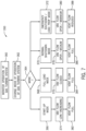
- FIG. 1 is a schematic block diagram of a gas turbine system 10 having a flow combiner 12 configured to combine different flows.
- the different flows may have substantially different flow rates, pressures temperatures, and fluid compositions.
- the different flows may correspond to a compressor bleed flow and a ventilation flow.
- the flow combiner 12 includes an outlet duct 14, a first inlet duct 16 (e.g., a compressor bleed inlet duct) coupled to the outlet duct 14, and a second inlet duct 18 (e.g., a ventilation inlet duct) coupled to the outlet duct 14).
- the first inlet duct 16 and the second inlet duct 18 couple to a common duct portion 20 of the outlet duct 14.
- the common duct portion 20 may include a flow combining (or mixing) section 22 having one or more flow mixers 24 (e.g., backflow inhibiters, flow baffles, flow dividers, flow conduits etc.).
- a the one or more flow mixers 24 include a backflow inhibiter 32 having a plurality of conduits 34 (e.g., a bundle of conduits) converging in a downstream flow direction of a fluid flow (e.g., compressor bleed flow 28 and ventilation flow 36) from the first and second inlet duct 16 and 18.
- a fluid flow e.g., compressor bleed flow 28 and ventilation flow 36
- the backflow inhibiter 32 (e.g., conduits 34) is configured to inhibit a backflow of the fluid flow (e.g., from the first inlet duct 16 to the second inlet duct 18, or vice versa).
- the backflow inhibiter 32 also may be configured to induce mixing of the fluid flows (e.g., 28, 36) in the common duct portion 20.
- the first inlet duct 16 may include or fluidly couple to a variable valve 26 (e.g., a variable bleed valve) configured to vary a fluid flow 28 (e.g., compressor bleed flow) entering the first inlet duct 16.
- variable valve 26 may be adjustable between open and closed positions (e.g., to increase or decrease a flow rate, pressure, etc.) to help control the intake of the fluid flow 28 into the flow combiner 12, reduce backflow of the fluid flow 28 into the second inlet duct 18, and improve mixing in the outlet duct 14.
- the variable valve 26 may include a plurality of adjustable valve elements 30 (e.g., rotatable doors or flaps).
- the second inlet duct 18 may include a damper 31 configured to open in response to the fluid flow 36 (e.g., ventilation flow) and close in response to the fluid flow 36 stopping.
- the damper 31 may be a gravity damper configured to close one or more pivoting doors (e.g., 1, 2, 3, 4, 5, or more hinged damper doors) by gravity when the fluid flow 36 stops.
- the damper 31 may be a spring-loaded damper configured to bias the pivoting doors toward a closed position, such that the fluid flow 36 opens the pivoting doors when the force of the fluid flow 36 is sufficient to overcome the spring force.
- the damper 31 also may be configured to inhibit a backflow of the fluid flow 28 into the second inlet duct 18 against the incoming fluid flow 36.
- the second inlet duct 18 also may include at least one fan 38 (e.g., 1, 2, or 3 fans) configured to force the fluid flow 36 into the second inlet duct 18.
- the damper 31 may be configured to open in response to operation of the fan 38 (i.e., fan turned on) and close when the fan 38 ceases operation (i.e., fan turned off).
- the speed of the fan 38 may be adjustable (e.g., increased or decreased) to help control the intake of the fluid flow 36, reduce backflow of the fluid flow 28 against the fluid flow 36, and improve mixing of the fluid flows 28 and 36 in the outlet duct 14.
- each silencer baffle 44 may include an outer enclosure (e.g., perforated wall) and internal sound absorption structure (e.g., sound absorption material, chambers, passages, baffles, etc.).
- Each silencer baffle 44 may be elongated in the downstream direction and may include an aerodynamic shape (e.g., an airfoil shape).
- the outlet duct 14 and the silencer section 42 e.g., silencer baffles 44
- the flow combiner 12 is used to combined two different flows (e.g., flows with different energy levels) from the gas turbine system 10.
- the flow combiner 12 may be configured to combine any number (e.g., 2, 3, 4, 5, 6, or more) different flows from the gas turbine system 10 or any other system generating different flows (e.g., different flow rates, pressures, etc.).
- the different flows may be described as high energy and low energy flows, wherein the high energy flow has a relatively higher pressure, a relatively higher temperature, and/or a relatively higher flow rate than the low energy flow.
- the compressor bleed flow 28 may be described as a high energy flow
- the ventilation flow 36 may be described as a low energy flow.
- the use of "high energy” and “low energy” with reference to flows may be used merely as a relative comparison of the flows.
- the high energy flow may have a pressure, temperature, and/or flow rate that is greater than the low energy flow by some percentage or multiplication factor (e.g., 1.1, 1.2, 1.3, 1.4, 1.5, 2, 2.5, 3, 4, 5, 10, 20, 30, 40, 50, or more).
- the flow combiner 12 may include additional inlet ducts similar to the inlet ducts 16 and 18.
- the flow combiner 12 is described in context of two combined flows from the gas turbine system 10, and more specifically a compressor bleed flow as the fluid flow 28 and a ventilation flow as the fluid flow 36.
- the gas turbine system 10 includes a gas turbine engine 50 coupled to a load 52, such as an electrical generator.
- the gas turbine system 10 may be stationary of mobile, such as a trailer mounted power plant (e.g., generator 52 driven by gas turbine engine 50).
- the gas turbine system 10 also includes a housing or enclosure 54 disposed about the gas turbine engine 50, such that a ventilation space or volume is disposed about the gas turbine engine 50 inside of the enclosure 54.
- the gas turbine engine 50 includes a compressor section or compressor 56 having one or more compressor stages (e.g., any number from 1 to 30 stages), a combustor section 58 having one or more combustors 60, and a turbine section or turbine 62 having one or more turbine stages (e.g., any number from 1 to 30 stages).
- Each compressor stage of the compressor 56 includes a plurality of compressor blades configured to compress an intake air.
- Each combustor 60 includes one or more fuel nozzles 64 configured to supply a fuel and compressed air 66 from the compressor 56 into a combustion chamber 68, where the fuel combusts to generate hot combustion gases 70.
- the hot combustion gases flow through the turbine 62 driving the one or more turbine stages to rotate a shaft 72 (e.g., one or more shafts) coupled to the turbine 62, the compressor 56, and the load 52.
- Each turbine stage of the turbine 62 includes a plurality of turbine blades driven by the hot combustion gases 70.
- the turbine 62 discharges the hot combustion gases 70 as an exhaust gas 74 into and through an exhaust section 76, such as an exhaust duct and/or exhaust stack.
- the gas turbine system 10 routes an intake air 80 through an air intake system 82 into the enclosure 54 and the compressor 56.
- the air intake system 82 includes a filter section 84 having one or more air filters 86, an air inlet duct 88 (e.g., ventilation intake duct) coupled to the enclosure 54, and an air inlet duct 90 (e.g., compressor intake duct) coupled to the compressor 56.
- the air inlet duct 88 couples to an intake port or opening 92 in the enclosure 54, and the air inlet duct 88 may include one or more fans 94 (e.g., electric motor driven fans) configured to help force a ventilation airflow 96 through the enclosure 54.
- the ventilation flow 96 enters the second inlet duct 18 (e.g., ventilation inlet duct) of the flow combiner 12 as the fluid flow 36.
- the air inlet duct 90 couples to (or extends through) an intake port or opening 92 in the enclosure 54, and the air inlet duct 90 extends internally into the enclosure 54 and couples to a compressor inlet 102 of the compressor 56.
- the air inlet duct 90 is configured to supply a compressor intake flow 104 into the compressor 56, which then compresses the air for use throughout the gas turbine engine 50.
- the compressed air 66 may be used for combustion and cooling in the combustor section 58, cooling in the turbine 62, and cooling elsewhere in the gas turbine engine 50.
- the compressed air 66 used for cooling may be bled from the compressor 56 at any suitable location (e.g., compressor bleed flow at various stages of the compressor 56). Additionally, the compressor bleed flow may be discharged from the gas turbine system 10 through the flow combiner 12.
- the first inlet duct 16 (e.g., compressor bleed inlet duct) of the flow combiner 12 is coupled to a compressor bleed portion 110 of the compressor 56.
- the first inlet duct 16 may include a compressor bleed intake conduit 112 coupled to an outer wall 114 of the compressor 56 at the compressor bleed portion 110.
- the compressor bleed intake conduit 112 may extend at least partially or entirely circumferentially around the outer wall 114 of the compressor 56, such as at least 180, 240, 300, or 360 degrees around the compressor 56.
- the compressor bleed intake conduit 112 may include a compressor opening 116 configured to fit around the outer wall 114 of the compressor 56.
- the outer wall 114 of the compressor 56 may include one or more compressor bleed openings configured to enable a compressor bleed flow into the first inlet duct 16.
- the first inlet duct 16 includes the variable valve 26 (e.g., variable bleed valve (VBV)) having one or more adjustable valve elements 30 (e.g., doors or flaps) configured to adjust the compressor bleed flow as the fluid flow 28 into the flow combiner 12.
- the variable valve 26 may include one or more electrical actuators, such as a common electric actuator or a separate electrical actuator for each of the plurality of adjustable valve elements 30.
- the gas turbine system 10, including the variable valve 26, the fan 38, the fan 94, the fuel injection via fuel nozzles 64, and other operating parameters, may be controlled by a control system 120 having a monitoring system 122 coupled to a controller 124.
- the monitoring system 122 includes a plurality of sensors 126 (indicated by S) distributed throughout the gas turbine system 10 to monitor various operating conditions.
- the sensors 126 may measure ambient conditions (e.g., humidity, temperature, etc.) outside of the gas turbine system 10.
- the sensors 126 may measure air intake conditions (e.g., flow rate, temperature, pressure) in the air intake system 82.
- the sensors 126 may measure compressor conditions (e.g., flow rate, temperature, and pressure of compressed air 66 and compressor bleed flow 28 from the compressor 56).
- the sensors 126 may measure ventilation conditions (e.g., flow rate, temperature, and pressure of the ventilation air flow 96 in the enclosure 54 and the ventilation flow 36 in the flow combiner 12).
- the sensors 126 may measure combustion conditions (e.g., fuel flow, fuel temperature, fuel pressure, fuel composition, Wobbe index, fuel-air ratio, flame temperature or intensity, combustion dynamics, and levels of emissions of pollutants such as NOx, SOx, CO 2 , CO, particulate matter, etc.).
- the sensors 126 may measure turbine conditions (e.g., flow rate, temperature, and pressure of combustion gases 70 in the turbine 62).
- the sensors 126 may also measure a rotational speed, a clearance between rotating blades and walls of the compressor 56 and the turbine 62, and vibration of the gas turbine engine 50.
- the sensors 126 may measure a load on the gas turbine engine 50, such as a part load or full load condition of the gas turbine engine 50.
- the sensors 126 may monitor an operating state of the gas turbine engine 50, such as a startup condition, a steady state condition, or a shut down condition.
- the sensors 126 may monitor generator parameters (e.g., power output), conditions on a power grid, output power from the turbine 62, and so forth.
- the sensors 126 may include a variety of sensor types to measure the foregoing parameters.
- the sensors 126 may include temperature sensors, such as thermocouples, thermistors, and the like, disposed in the flow combiner 12 and throughout the gas turbine system 10.
- the sensors 126 may also include flow sensors, such as flowmeters (e.g., differential pressure flowmeters, velocity flowmeters, mass flowmeters, positive displacement flowmeters, open channel flowmeters) and liquid level sensors such as continuous level transmitters, ultrasonic transducers, laser level transmitters, and so on, disposed in the flow combiner 12 and throughout the gas turbine system 10.
- flowmeters e.g., differential pressure flowmeters, velocity flowmeters, mass flowmeters, positive displacement flowmeters, open channel flowmeters
- liquid level sensors such as continuous level transmitters, ultrasonic transducers, laser level transmitters, and so on
- the sensors 126 may include pressure sensors, such as piezo-resistive pressure sensors, differential pressure sensors, optical pressure sensors, and so on, included in the flow combiner 12 and throughout the gas turbine system 10.
- Fuel properties may be sensed and/or otherwise provided to the controller 124, e.g., via a human operator interface in the flow combiner 12 and the gas turbine system 10.
- the fuel properties may include moisture content, carbon content, chemical composition, specific gravity, ambient temperature, energy content, certain "numbers" (e.g., Wobbe Index, cetane number, octane number, and so on), or a combination thereof.
- Exhaust emissions may be measured by emissions sensors, such as NOx sensors, SOx sensors, CO 2 sensors, and CO sensors.
- the controller 124 is configured to receive and process the measured input from the sensors 126 and control operation of the gas turbine system 10, including the fluid flows 28, 36, and 40 through the flow combiner 12.
- the controller 124 includes one or more processors 128, memory 130, and instructions 132 stored on the memory 130 and executable by the processors 128 to control operation of the gas turbine system 10.
- the processors 128 may include one or more "general-purpose" microprocessors, one or more special-purpose microprocessors, and/or one or more application specific integrated circuits (ASICS), or some combination thereof.
- ASICS application specific integrated circuits
- the processor 128 may include one or more reduced instruction set (RISC) processors.
- the memory 130 may store information such as control software, look up tables, configuration data, etc.
- the memory 130 may include a tangible, non-transitory, machine-readable medium, such as a volatile memory (e.g., a random access memory (RAM)) and/or a nonvolatile memory (e.g., a read-only memory (ROM), flash memory, a hard drive, or any other suitable optical, magnetic, or solid-state storage medium, or a combination thereof).
- a volatile memory e.g., a random access memory (RAM)
- a nonvolatile memory e.g., a read-only memory (ROM), flash memory, a hard drive, or any other suitable optical, magnetic, or solid-state storage medium, or a combination thereof.
- the memory 130 may store a variety of information, which may be suitable for various purposes.
- the memory 130 may store machine-readable and/or processor-executable instructions 132 (e.g., firmware or software) for the processor execution.
- the controller 124 may be communicatively coupled to an operator interface 134 (e.g., a human machine interface (HMI)), and one or more actuators suitable for controlling components of the gas turbine system 10.
- an actuator e.g., electric actuator
- the controller 124 also may be coupled to valves, switches, positioners, pumps, and the like, suitable for controlling the various components of the gas turbine engine 50.
- the controller 124 may receive data from the sensors 126, and may be used to control the compressor 56, the combustors 60, the turbine 62, the load 52, and flows through the flow combiner 12.
- the controller 124 is configured to control the fluid flows 28, 36, and 40 through the flow combiner 12 based on various sensor feedback and operational modes of the gas turbine system 10 (e.g., startup mode, steady state mode, shutdown mode, emergency mode, full load mode, part load mode, etc.). In each of these modes, the controller 124 may adjust the variable valve 26 to adjust (e.g., increase or decrease) the compressor bleed flow 28, adjust one or both of the fans 38 and 94 to adjust (e.g., increase or decrease) the ventilation flow 36, or a combination thereof.
- various sensor feedback and operational modes of the gas turbine system 10 e.g., startup mode, steady state mode, shutdown mode, emergency mode, full load mode, part load mode, etc.
- the controller 124 may adjust the variable valve 26 to adjust (e.g., increase or decrease) the compressor bleed flow 28, adjust one or both of the fans 38 and 94 to adjust (e.g., increase or decrease) the ventilation flow 36, or a combination thereof.
- FIGS. 2, 3, and 4 are detailed views of an embodiment of the flow combiner 12 of FIG. 1 .
- FIG. 2 is a perspective view of an embodiment of the flow combiner 12 of FIG. 1 .
- FIG. 3 is a side view of an embodiment of the flow combiner of FIG. 2.
- FIG. 4 is a front view of an embodiment of the flow combiner of FIG. 2 . Additional details of the flow combiner 12 are now described with reference to FIGS. 2-4 .
- the illustrated inlet ducts 16 and 18 converge toward another and the outlet duct 14 in a Y-shaped structure 138.
- the inlet ducts 16 and 18 may converge at an angle 140, such as 10 to 120 degrees, 20 to 90 degrees, or 30 to 60 degrees.
- the inlet duct 16 may turn from the compressor bleed intake conduit 112 toward the common duct portion 20 of the outlet duct 14.
- the compressor bleed intake conduit 112 may be substantially parallel to the outlet duct portion 14.
- the inlet duct 18 may turn from a fan housing portion 142 (e.g., upstream duct portion having inlet 144) toward the common duct portion 20 of the outlet duct 14.
- the fan housing portion 142 may be substantially perpendicular to the outlet duct portion 14.
- the flow combiner 12 also may include an intermediate duct portion 150 (e.g., diverging duct portion) between the compressor bleed intake conduit 112 and the common duct portion 20, and an intermediate duct portion 152 (e.g., diverging duct portion) between the fan housing portion 142 and the common duct portion 20.
- These intermediate duct portions 150 and 152 may define the angle 140 of convergence of the inlet ducts 16 and 18.
- the diverging duct portion 150 of the first inlet duct 16 (e.g., compressor bleed inlet duct) and the diverging duct portion 152 of the second inlet duct 18 (e.g., ventilation inlet duct) may help to control the combination of the fluid flows 26 and 38 into the common duct portion 20.
- the diverging duct portion 150 has duct walls 154 that diverge and a cross-sectional flow area 156 that expands or increases in a downstream direction of the fluid flow 28.
- the diverging duct portion 152 has duct walls 158 that diverge and a cross-sectional flow area 160 that expands or increases in a downstream direction of the fluid flow 36.
- the cross-sectional flow areas 156 and 158 of the inlet ducts 16 and 18 may be entirely or partially constant, diverging, and/or converging in the downstream direction of the fluid flows 28 and 36, respectively. Additionally, a first minimum of the cross-sectional flow area 156 of the inlet duct 16 may be equal to, greater than, or less than a second minimum of the cross-sectional flow area 158 of the inlet duct 18 (e.g., the first minimum may be greater than the second minimum if the fluid flow 28 is a higher energy flow than the fluid flow 36).
- a first maximum of the cross-sectional flow area 156 of the inlet duct 16 may be equal to, greater than, or less than a second maximum of the cross-sectional flow area 158 of the inlet duct 18 (e.g., the first maximum may be greater than the second maximum if the fluid flow 28 is a higher energy flow than the fluid flow 36).
- the divergence of duct walls 154 and/or the expansion of the cross-sectional flow area 156 may be the same or different (e.g., greater for a higher energy flow) than the divergence of duct walls 158 and/or the expansion of the cross-sectional flow area 160.
- the common duct portion 20 of the outlet duct 14 may have a cross-sectional flow area 162 that is greater than both the cross-sectional flow area 156 of the inlet duct 16 and the cross-sectional flow area 160 of the inlet duct 18.
- the common duct portion 20 may include the flow combining section 22 with the plurality of flow mixers 24 (e.g., conduits, channels, baffles, etc. to help guide the flows being mixed together).
- the flow mixers 24 include the backflow inhibiter 32 having the plurality of conduits 34 converging in the downstream flow direction of the fluid flow (e.g., 28, 36), thereby helping to inhibit backflow while combining and mixing the fluid flow in the common duct portion 20.
- the outlet duct 14 also may include a diverging duct portion 164 that diverges in a downstream direction of the combined fluid flow 40.
- the silencer section 42 may be disposed in a uniform duct portion 166 having a cross-sectional flow area 168 that is constant in the downstream direction of the combined fluid flow 40.
- the outlet duct 14 may include a discharge section 170 having oppositely oriented turning duct portions 172 and 174, which help disperse the combined flow 40 being discharged into the atmosphere.
- the turning duct portions 172 and 174 may include internal turning vanes or baffles 176 and 178, respectively.
- the baffles 176 and 178 are configured to split the combined fluid flow 40 and guide the split flows outwardly through the turning duct portions 172 and 174.
- the flow combiner 12 may include various flow controls configured to control a ratio of the fluid flow 28 relative to the fluid flow 36, thereby helping to improve the combination of the fluid flows 28 and 36 without causing undesirable backflow and/or overloading the silencer section 42.
- the illustrated embodiment includes the variable valve 26 (e.g., variable bleed valve (VBV)) having the plurality of adjustable valve elements 30 (e.g., doors or flaps that open and close) spaced circumferentially about the compressor opening 116, which is configured to extend around the outer wall 114 of the compressor 56 as illustrated in FIG. 1 .
- VBV variable bleed valve
- the adjustable valve elements 30 may include actuators (e.g., electric actuators) coupled to the controller 124, such that the controller 124 can adjust the position of the adjustable valve elements 30 based on sensor feedback to help improve the flow combination in the flow combiner 12.
- the adjustable valve elements 30 may be configured to rotate and/or move axially between open and closed positions.
- the illustrated embodiment also includes the plurality of fans 38 in the inlet duct 18.
- the controller 124 is configured to selectively operate (i.e., turn on or off) and adjust the speed of (e.g., increase or decrease the fan speed of) each of the fans 38 independently or in combination with one another based on sensor feedback to help improve the flow combination in the flow combiner 12.
- the illustrated embodiment includes three fans 38 arranged in parallel in the inlet duct 18.
- embodiments of the flow combiner 12 may have any number of fans 38 (e.g., 1, 2, 3, 4, 5, 6, 7, 8, 9, or 10) arranged in series, in parallel, or a combination thereof.
- the controller 124 can help enable a successful combination of the fluid flows 28 and 36 in the flow combiner 12 without causing backflow (e.g., backflow of the fluid flow 28 into the inlet duct 18) or overloading the flow combiner 12.
- the inlet duct 18 also includes the damper 31 configured to open in response to the fluid flow 36 and close in response to the fluid flow 36 stopping.
- the flow combiner 12 combines or mixes two different types of flows, e.g., the compressor bleed flow 28 (e.g., a variable bleed valve (VBV) flow) extracted or bled from the compressor 56 and the ventilation flow 36, 96 from the enclosure 54 surrounding the gas turbine engine 50.
- the compressor bleed flow 28 may be a high energy variable flow compared to the ventilation flow 36, which may be a continuous low energy flow.
- the compressor bleed flow 28 may have a pressure range of 15 to 40 psi or any other suitable pressure range depending on the extraction point on the compressor 56.
- the ventilation flow 36 may have a pressure range of 10 to 15 psi or any other suitable pressure range for ventilating the enclosure 54.
- the compressor bleed flow 28 may be a high-temperature flow compared to the ventilation flow 36, which may be a low-mid temperature flow.
- the compressor bleed flow 28 may have a temperature range of 260°F to 300°F (399.82K to 422.04K).
- the ventilation flow 36 may have a temperature range of 120°F to 200°F (322.04K to 366.48K).
- the compressor bleed flow 28 may operate as a discrete flow during certain time intervals that may range in duration from 1 to 10 seconds or any other suitable time duration.
- the ventilation flow 36 may operate as a continuous flow.
- the flow combiner 12 is able to successfully combine the flows 28 and 36 using the variable valve 26, the fans 38, the damper 31, and the backflow inhibiter 32 while using a common silencer section 42.
- the controller 124 may control flow rates of both flows 28 and 36 based on a particular mode of operation of the gas turbine system 10. The various modes of operation of the gas turbine system 10 will be described in more detail below.
- FIG. 5 is a perspective view of an embodiment of the backflow inhibiter 32 of the flow combiner 12 as illustrated in FIG. 1 and 3 , further illustrating an embodiment of the plurality of conduits 34 of the backflow inhibiter 32.
- the plurality of conduits 34 are configured to help combine and mix the fluid flows 28 and 36 from the first and second inlet ducts 16 and 18 while inhibiting backflow from one inlet duct to another (e.g., from the first inlet duct 16 into the second inlet duct 18 and into the enclosure 54).
- each conduit 34 has a cross-sectional flow area 180 that shrinks or decreases in the downstream flow direction.
- each conduit 34 may have a tapered geometry 182, e.g., duct walls 184 that are angled toward one another in the downstream flow direction of the fluid flow (e.g., 28 and 36).
- each conduit 34 may include a conical shaped conduit, a tapered square shaped conduit, or a tapered polygonal shaped conduit.
- the backflow inhibiter 32 may include any number of plurality of conduits 34 (e.g., 2, 3, 4, 5, 6, 7, 8, 9, 10, 15, 20, or more).
- the conduits 34 may include two or more conduits of the same size and shape, two or more conduits of different sizes, two or more conduits of different shapes, or any combination thereof.
- Each conduit 34 includes an inlet 186 and an outlet 188 having a downstream edge 190.
- Each conduit 34 has a first dimension 192 at the inlet 186 and a second dimension 194 at the outlet 188.
- the dimensions 192 and 194 may include a width, a diameter, or a cross-sectional flow area of the conduit 34.
- the dimension 194 of the outlet 188 is less than the dimension 192 of the inlet 186 by some percentage or factor to help inhibit backflow.
- the dimension 194 may be less than or equal to approximately 10, 20, 30, 40, 50, 60, 70, or 80 percent of the dimension 192.
- the dimension 192 may correspond to a maximum dimension of the conduit 34 while the dimension 194 may correspond to a minimum dimension of the conduit 34.
- the outlet 188 may also define a throat or flow restriction orifice that regulates the fluid flow (e.g., 28 and 36) and inhibits the backflow.
- the dimensions 192 and 194 may be selected to restrict or regulate the fluid flow (e.g., 28 and 36) from the inlet ducts 16 and 18 into the outlet duct 14 of the flow combiner 12, while also inhibiting backflow of the fluid flow (e.g., compressor bleed flow 28 into the inlet duct 18).
- the dimensions 192 and 194 may be increased to increase the fluid flow (e.g., 28 and 36), or the dimensions 192 and 194 may be decreased to reduce the fluid flow (e.g., 28 and 36).
- the conduits 34 also may vary in size, shape, quantity, and rate of convergence (or angle of convergence) from the inlet 186 to the outlet 188 to help regulate the fluid flow (e.g., 28 and 36) and inhibit backflow.
- the downstream edge 190 of the outlet 188 may be a smooth edge or a variable edge (e.g., a jagged or toothed edge having a plurality of teeth 196).
- the variable edge with teeth 196 may be configured to help spread the fluid flow (e.g., 28 and 36) into the flow combiner 12 while also adding additional surface area to inhibit backflow.
- FIG. 6 is a schematic cross-sectional side view of the flow combiner 12 coupled to the compressor 56 of the gas turbine system 10 of FIG. 1 , illustrating the compressor bleed intake conduit 112 having the variable valve 26 (e.g., variable bleed valve (VBV)) configured to adjust the compressor bleed flow 28 into the flow combiner 12.
- the compressor bleed intake conduit 112 may be an integral portion (i.e., one-piece) with the inlet duct 16 of the flow combiner 12, or the compressor bleed intake conduit 112 may be a separate piece removably or fixedly coupled to the inlet duct 16.
- the compressor 56 is disposed inside of the compressor bleed intake conduit 112 along the compressor opening 116.
- the compressor opening 116 is annular and thus fits around the outer wall 114 (e.g., annular wall) of the compressor 56.
- the compressor opening 116 and the outer wall 114 may have other shapes at the connection between the compressor bleed intake conduit 112 and the compressor 56.
- the compressor bleed intake conduit 112 includes the variable valve 26 having the plurality of adjustable valve elements 30 (e.g., doors or flaps) disposed circumferentially about the compressor opening 116.
- the adjustable valve elements 30 help regulate the compressor bleed flow 28 in the inlet duct 16, and thus within the flow combiner 12.
- the adjustable valve elements 30 may be a collection of circumferentially spaced valves, doors, or flaps, which are configured to rotate or move axially between open and closed positions.
- the adjustable valve elements 30 may vary in size, shape, and quantity. A uniform or non-uniform circumferential gap may be present between the adjustable valve elements 30.
- each of the adjustable valve elements 30 may be separated from one another via a circumferential gap with a regular interval size such as 6 inches (15.24cm), 1 foot (30.48cm), or any other suitable distance.
- openings and closings of the adjustable valve elements 30 may be regulated via a drive 200.
- the adjustable valve elements 30 may open and close simultaneously or periodically to adjust the compressor bleed flow 28.
- the drive 200 may include an electric drive, a fluid drive (e.g., a hydraulic drive and/or a pneumatic drive), or a combination thereof.
- the drive 200 may be coupled to an energy source 202 and one or more actuators 204 coupled to the adjustable valve elements 30.
- the energy source 202 may include an electrical power supply and/or a fluid supply (e.g., a pressurized fluid tank, a compressor, or a pump).
- the drive 200 is configured to move the actuators 204, which in turn move the adjustable valve elements 30 between open and closed positions.
- the actuators 204 may include mechanical linkages, rotational joints, piston-cylinder assemblies, or transmission assemblies configured to transfer a force from the drive 200 to the adjustable valve elements 30.
- the drive 200 uses pressurized fluid (e.g., liquid or gas) from the energy source 202 (e.g., fluid supply) to provide the force to regulate the openings and closings of the adjustable valve elements 30.
- the drive 200 e.g., fluid drive
- the drive 200 may include a piston-cylinder assembly driven by the pressurized fluid from the energy source 202.
- the drive 200 may be controlled by the controller 124 to adjust the position of the adjustable valve elements 30 and thus vary the flow of the compressor bleed flow 28 through the flow combiner 12.
- FIG. 7 is a flow chart of an embodiment of a method 350 of operating the gas turbine system 10 in different modes using the flow combiner 12 of FIGS. 1-6 .
- the modes of operation may not be limited to the modes described herein, but rather serve as examples.
- the flow rates associated with the compressor bleed flow 28 and the ventilation flow 36 may be continuously or periodically monitored by the controller 124 via a control algorithm.
- the method 350 includes monitoring operation of the gas turbine system 10 as indicated by block 360, and changing a mode of operation of the gas turbine system 10 based on monitored conditions as indicated by block 362. The method 350 may then query for the mode of operation as indicated by block 364 and proceed with changes depending on the mode of operation.
- the method 350 may control the variable valve 26 to adjust the compressor bleed flow 28 (e.g., variable bleed valve (VBV) flow) to be relatively low and/or increasing as the gas turbine engine 12 is speeding up, as indicated by block 374. Additionally, in the start-up mode 366, the method 350 may control the fans 38 and/or 94 to adjust the ventilation flow 36, 96 to be at a full flow (e.g., vent flow full), as indicated by block 382. During start-up mode 366, the compressor bleed flow 28 may be increasing but still may operate at a low amount of flow while the ventilation flow 36 may be operating at full flow.
- VBV variable bleed valve
- the blades of the compressor are increasing in rotational speed to attain a threshold speed of the gas turbine engine 50.
- the compressor bleed flow 28 may operate at a low flow when the gas turbine engine 50 is starting up or beginning to rotate.
- the compressor bleed flow 28 may increase but still operate at a lower flow rate compare to the maximum flow rate.
- the ventilation flow 36 may be operating at full flow.
- the method 350 may control the variable valve 26 to adjust the compressor bleed flow 28 (e.g., VBV flow) to be fully closed (or nearly closed) as the gas turbine engine 12 is operating at a full load, as indicated by block 376. Additionally, in the full load mode 368, the method 350 may control the fans 38 and/or 94 to adjust the ventilation flow 36, 96 to be at a full flow (e.g., vent flow full), as indicated by block 384. During full load mode 368, the compressor bleed flow 28 may be closed while the ventilation flow 36 may be operating at full flow. When the gas turbine engine 50 is operating at full load mode, the gas turbine engine 50 may be releasing a maximum amount of heat. As a result, the ventilation flow 36 operating at full flow may be useful in cooling the gas turbine engine 50 and the space inside the enclosure 54.
- VBV flow compressor bleed flow
- the method 350 may control the variable valve 26 to adjust the compressor bleed flow 28 (e.g., VBV flow) to be open at a medium flow as the gas turbine engine 12 is shutting down in a normal manner, as indicated by block 378.
- the medium flow of the compressor bleed flow 28 may be an intermediate level between no flow and a maximum flow.
- the method 350 may control the fans 38 and/or 94 to adjust the ventilation flow 36, 96 to be at a full flow (e.g., vent flow full), as indicated by block 386.
- the gas turbine engine 50 may be gradually slowing down (rather than an urgent or rapid slowing down) due to some unexpected event or emergency.
- the variable valve 26 may be opened such that the compressor bleed flow 28 may be operating at a medium amount of flow, while the ventilation flow 36 may be operating at full flow.
- the method 350 may control the variable valve 26 to adjust the compressor bleed flow 28 (e.g., VBV flow) to be open at a maximum flow as the gas turbine engine 12 may be rapidly shutting down and/or unexpectedly dropping a load in an urgent manner, as indicated by block 380. Additionally, in the mode 372, the method 350 may control the fans 38 and/or 94 to adjust the ventilation flow 36, 96 to be at a reduced or partial flow (e.g., vent flow reduced less than full flow), as indicated by block 388. During the emergency shutdown and/or load drop mode 372, the compressor bleed flow 28 may be operating at a maximum amount of flow while the ventilation flow 36 may be operating at a reduced amount of flow.
- VBV flow compressor bleed flow 28
- the ventilation flow 36 may be operating at a reduced amount of flow.
- the compressor bleed flow 28 may be operating at full capacity in order to reduce the possibility of the gas turbine engine 50 surging or stalling.
- the compressor bleed flow 28 may be operated at full capacity for a short period of time such as 5 seconds, 10 seconds, or any other suitable time period. Since the compressor bleed flow 28 may be operating at full flow for a reduced amount of time, the flow rate of the ventilation flow 36 may also be reduced.
- the flow combiner 12 as described above with reference to FIGS. 1-6 is configured to combine the fluid flows 28 and 36 with the foregoing controls provided by the method 350 of FIG. 7 , thereby helping to reduce the possibility of backflow and avoid overloading the silencer section 42 and other portions of the flow combiner 12.
- the illustrated method 350 has some specific modes of operation and corresponding adjustments to the fluid flows 28 and 36, other modes of operation and adjustments to the fluid flows 28 and 36 may be used to help combine the flows through the flow combiner 12.
- the flow combiner 12 may include a shared or common silencer section 42 to attenuate noise from the combined flow 40 (i.e., combination of the compressor bleed flow 28 and the ventilation flow 36).
- the controller 124 may regulate the flow rates associated with the compressor bleed flow 28 and the ventilation flow 36 continuously or periodically based on various modes of operation of the gas turbine system 10.
- the flow combiner 12 that enables the mixing of the compressor bleed flow 28 and the ventilation flow 36 includes two different inlet ducts 16 and 18.
- the inlet duct 16 may be designated as an inlet for the bleed flow 28 to enter the flow combiner 12 while the inlet duct 18 may be designated as an inlet for the ventilation flow 36 to enter the flow combiner 12.
- both flows may merge within the flow combiner 12.
- the inlet duct 16 may include the adjustable valve elements 30 that regulate the volume of the compressor bleed flow 28 via the drive 200 and actuators 204.
- the inlet duct 18 may include one or more fans 38 and the damper 31 to regulate the ventilation flow 36 and inhibit backflow of the compressor bleed flow 28 through the inlet duct 18.
Landscapes
- Engineering & Computer Science (AREA)
- Mechanical Engineering (AREA)
- General Engineering & Computer Science (AREA)
- Chemical & Material Sciences (AREA)
- Combustion & Propulsion (AREA)
- Physics & Mathematics (AREA)
- Fluid Mechanics (AREA)
- Geometry (AREA)
- Structures Of Non-Positive Displacement Pumps (AREA)
Claims (8)
- System, umfassend:
einen Strömungskombinierer (12), umfassend:einen Auslasskanal (14);einen Verdichterzapflufteinlasskanal (16), der mit dem Auslasskanal (14) gekoppelt ist, wobei der Verdichterzapflufteinlasskanal (16) konfiguriert ist, um eine Zapfluftströmung (28) von einem Verdichter (56) eines Gasturbinentriebwerks (50) aufzunehmen; undeinen Lüftungseinlasskanal (18), der mit dem Auslasskanal (14) gekoppelt ist, wobei der Lüftungseinlasskanal (18) konfiguriert ist, um eine Lüftungsströmung (36) von einem Gehäuse (54) aufzunehmen, das das Gasturbinentriebwerk (50) umgibt,wobei die Zapfluftströmung (28) und die Lüftungsströmung (36) als eine Auslassströmung durch den Auslasskanal (14) kombiniert werden,wobei der Verdichterzapflufteinlasskanal (16) und der Lüftungseinlasskanal (18) sich mit einem gemeinsamen Kanalabschnitt (20) des Auslasskanals (14) koppeln, wobei der gemeinsame Kanalabschnitt (20) eine Rückströmungssperre (32), die eine Vielzahl von Leitungen (34) aufweist, umfasst, und wobei jede Leitung (34) einen Querschnittsströmungsbereich (180) aufweist, der in eine stromabwärtige Strömungsrichtung abnimmt. - System nach Anspruch 1, wobei der Verdichterzapflufteinlasskanal (16) eine Verdichteröffnung (116) umfasst, die konfiguriert ist, um sich um eine Außenwand (114) des Verdichters (56) umfänglich zu erstrecken, wobei der Verdichterzapflufteinlasskanal (16) ein variables Entlüftungsventil (26) umfasst.
- System nach Anspruch 1, wobei der Lüftungseinlasskanal (18) einen Drehkanalabschnitt (172, 174) umfasst, der mit dem gemeinsamen Kanalabschnitt (20) gekoppelt ist.
- System nach Anspruch 1, wobei der Lüftungseinlasskanal (18) eine Luftklappe (31) umfasst, die konfiguriert ist, um sich als Reaktion auf die Lüftungsströmung (36) zu öffnen, und wobei der Verdichterzapflufteinlasskanal (16) eine Vielzahl von einstellbaren Ventilelementen (30) umfasst, um die Zapfluftströmung (28) innerhalb des Strömungskombinierers (12) zu regulieren.
- System nach Anspruch 1, wobei der Auslasskanal (14) eine oder mehrere Schalldämpferblenden (44) umfasst.
- Verfahren, umfassend:Aufnehmen einer Zapfluftströmung (28) von einem Verdichter (56) eines Gasturbinentriebwerks (50) in einen Verdichterzapflufteinlasskanal (16), der mit einem Auslasskanal (14) eines Strömungskombinierers (12) gekoppelt ist; undAufnehmen einer Lüftungsströmung (36) von einem Gehäuse (54), das das Gasturbinentriebwerk (50) umgibt, in einen Lüftungseinlasskanal (18), der mit dem Auslasskanal (14) gekoppelt ist, wobei die Zapfluftströmung (28) und die Lüftungsströmung (36) als eine Auslassströmung durch den Auslasskanal (14) kombiniert werden,wobei der Verdichterzapflufteinlasskanal (16) und der Lüftungseinlasskanal (18) sich mit einem gemeinsamen Kanalabschnitt (20) des Auslasskanals (14) koppeln, wobei der gemeinsame Kanalabschnitt (20) eine Rückströmungssperre (32), die eine Vielzahl von Leitungen (34) aufweist, umfasst, und wobei jede Leitung (34) einen Querschnittsströmungsbereich (180) aufweist, der in eine stromabwärtige Strömungsrichtung abnimmt.
- Verfahren nach Anspruch 6, umfassend das Einstellen, über eine Steuervorrichtung (124), der Zapfluftströmung (28) oder der Lüftungsströmung (36) basierend auf einem oder mehreren Betriebsparametern des Gasturbinentriebwerks (50).
- Verfahren nach Anspruch 7, wobei der eine oder die mehreren Betriebsparameter einen Betriebsmodus des Gasturbinentriebwerks (50) umfassen, wobei der Betriebsmodus des Gasturbinentriebwerks (50) einen von einem Anlaufmodus (366), einem Volllastmodus (368), einem normalen Abschaltmodus (370) oder einem Notfallabschaltungs-/Lastabfallmodus (372) umfasst.
Applications Claiming Priority (1)
| Application Number | Priority Date | Filing Date | Title |
|---|---|---|---|
| US16/875,989 US11572829B2 (en) | 2020-05-16 | 2020-05-16 | System and method for combining compressor bleed flow and ventilation flow of gas turbine engine |
Publications (2)
| Publication Number | Publication Date |
|---|---|
| EP3910175A1 EP3910175A1 (de) | 2021-11-17 |
| EP3910175B1 true EP3910175B1 (de) | 2024-03-13 |
Family
ID=75746354
Family Applications (1)
| Application Number | Title | Priority Date | Filing Date |
|---|---|---|---|
| EP21171366.4A Active EP3910175B1 (de) | 2020-05-16 | 2021-04-29 | System und verfahren zur kombination von verdichterausblasströmung und ventilationsströmung eines gasturbinenmotors |
Country Status (4)
| Country | Link |
|---|---|
| US (1) | US11572829B2 (de) |
| EP (1) | EP3910175B1 (de) |
| JP (1) | JP7721309B2 (de) |
| CN (1) | CN113685271B (de) |
Cited By (1)
| Publication number | Priority date | Publication date | Assignee | Title |
|---|---|---|---|---|
| EP4722104A1 (de) * | 2024-10-01 | 2026-04-08 | RTX Corporation | Antriebssystem mit offenem rotor und abgasmischer(n) |
Families Citing this family (3)
| Publication number | Priority date | Publication date | Assignee | Title |
|---|---|---|---|---|
| DE102019204422A1 (de) * | 2019-03-29 | 2020-10-01 | Siemens Aktiengesellschaft | Vorhersage einer Verbrennungsdynamik einer Gasturbine |
| JP7637082B2 (ja) * | 2022-02-02 | 2025-02-27 | 日立グローバルライフソリューションズ株式会社 | 冷蔵庫 |
| US20250146441A1 (en) * | 2023-11-02 | 2025-05-08 | Rtx Corporation | Turbine cooling air pressure boost system |
Family Cites Families (40)
| Publication number | Priority date | Publication date | Assignee | Title |
|---|---|---|---|---|
| US3377804A (en) | 1966-06-13 | 1968-04-16 | Gen Electric | Flow mixers particularly for gas turbine engines |
| US3586171A (en) | 1969-05-09 | 1971-06-22 | Tenneco Inc | Combination dual-flow and two-stage filter |
| US4565505A (en) | 1983-04-11 | 1986-01-21 | Woollenweber William E | Combination flow turbine for internal combustion engine turbochargers |
| EP0289882A1 (de) | 1987-05-06 | 1988-11-09 | Wilhelm A. Keller | Strömungsmischer |
| GB2259328B (en) | 1991-09-03 | 1995-07-19 | Gen Electric | Gas turbine engine variable bleed pivotal flow splitter |
| US5281087A (en) | 1992-06-10 | 1994-01-25 | General Electric Company | Industrial gas turbine engine with dual panel variable vane assembly |
| US5325661A (en) | 1993-04-14 | 1994-07-05 | The United States Of America As Represented By The Administrator Of The National Aeronautics And Space Administration | Jet mixer noise suppressor using acoustic feedback |
| CA2133793A1 (en) | 1994-10-06 | 1996-04-07 | William E. Carscallen | Inter compressor duct variable geometry annular diffuser/bleed valve |
| JP3899916B2 (ja) * | 2001-12-07 | 2007-03-28 | 石川島播磨重工業株式会社 | ガスタービン換気装置 |
| JP2005140068A (ja) * | 2003-11-10 | 2005-06-02 | Tokyo Electric Power Co Inc:The | 発電システム |
| JP4820669B2 (ja) | 2006-03-16 | 2011-11-24 | 株式会社荏原製作所 | 排気装置、排気装置の運転方法 |
| US7698898B2 (en) | 2007-04-04 | 2010-04-20 | General Electric Company | Mixer for cooling and sealing air system for turbomachinery |
| US8505310B2 (en) | 2008-10-22 | 2013-08-13 | General Electric Company | Gas turbine ejector and method of operation |
| US8087491B2 (en) * | 2010-01-08 | 2012-01-03 | General Electric Company | Vane type silencers in elbow for gas turbine |
| US20130327012A1 (en) * | 2012-06-11 | 2013-12-12 | General Electric Company | Gas turbine anti-icing system |
| US9003762B2 (en) | 2012-10-02 | 2015-04-14 | General Electric Company | Turbine exhaust plume mitigation system |
| US20140126991A1 (en) * | 2012-11-07 | 2014-05-08 | General Electric Company | Systems and methods for active component life management for gas turbine engines |
| PL225191B1 (pl) * | 2012-12-06 | 2017-03-31 | Gen Electric | Układ silnika turbiny gazowej zawierającej zespół sterowania strumieniem spalin i zespół sterowania strumieniem spalin w układzie silnika turbiny gazowej |
| US9611752B2 (en) | 2013-03-15 | 2017-04-04 | General Electric Company | Compressor start bleed system for a turbine system and method of controlling a compressor start bleed system |
| US9534536B2 (en) * | 2013-07-02 | 2017-01-03 | General Electric Company | Turbine flow modulation for part load performance |
| US9822662B2 (en) | 2013-11-08 | 2017-11-21 | Siemens Energy, Inc. | Cooling system with compressor bleed and ambient air for gas turbine engine |
| US10036321B2 (en) * | 2014-05-29 | 2018-07-31 | General Electric Company | Systems and methods for utilizing gas turbine compartment ventilation discharge air |
| WO2016028974A1 (en) * | 2014-08-21 | 2016-02-25 | Williams International Co., L.L.C. | Valvular-conduit manifold |
| US9752503B2 (en) * | 2015-06-29 | 2017-09-05 | General Electric Company | Power generation system exhaust cooling |
| US9850818B2 (en) * | 2015-06-29 | 2017-12-26 | General Electric Company | Power generation system exhaust cooling |
| US10030558B2 (en) * | 2015-06-29 | 2018-07-24 | General Electric Company | Power generation system exhaust cooling |
| US9752502B2 (en) * | 2015-06-29 | 2017-09-05 | General Electric Company | Power generation system exhaust cooling |
| US9938874B2 (en) * | 2015-06-29 | 2018-04-10 | General Electric Company | Power generation system exhaust cooling |
| US20160376908A1 (en) | 2015-06-29 | 2016-12-29 | General Electric Company | Power generation system exhaust cooling |
| US9840953B2 (en) * | 2015-06-29 | 2017-12-12 | General Electric Company | Power generation system exhaust cooling |
| US10060349B2 (en) * | 2015-11-06 | 2018-08-28 | General Electric Company | System and method for coupling components of a turbine system with cables |
| US10584615B2 (en) * | 2015-12-15 | 2020-03-10 | General Electric Company | System for generating steam via turbine extraction and compressor extraction including an ejector and static mixer |
| US9976479B2 (en) * | 2015-12-15 | 2018-05-22 | General Electric Company | Power plant including a static mixer and steam generating system via turbine extraction and compressor extraction |
| US20170306845A1 (en) * | 2016-04-22 | 2017-10-26 | General Electric Company | Ventilation system for turbomachine using bladeless airflow amplifier |
| US20170306846A1 (en) * | 2016-04-22 | 2017-10-26 | General Electric Company | Ventilation system for turbomachine using bladeless airflow amplifier |
| JP6639338B2 (ja) * | 2016-07-11 | 2020-02-05 | 三菱日立パワーシステムズ株式会社 | ガスタービン及びガスタービンの運転方法 |
| IT201600107332A1 (it) | 2016-10-25 | 2018-04-25 | Nuovo Pignone Tecnologie Srl | Sistema di turbina a gas con disposizione per convogliare lo spurgo / gas turbine system with bleed routing arrangement |
| EP3418525A1 (de) * | 2017-06-22 | 2018-12-26 | General Electric Company | Rückflussverhinderungssystem für ein gasturbinentriebwerk |
| US11117669B2 (en) | 2018-07-30 | 2021-09-14 | Gulfstream Aerospace Corporation | Vane assembly for distribution of a stratified fluid in an aircraft |
| US11578621B2 (en) * | 2020-04-08 | 2023-02-14 | General Electric Company | System for cooling turbine shaft coupling |
-
2020
- 2020-05-16 US US16/875,989 patent/US11572829B2/en active Active
-
2021
- 2021-04-14 CN CN202110403169.1A patent/CN113685271B/zh active Active
- 2021-04-20 JP JP2021071468A patent/JP7721309B2/ja active Active
- 2021-04-29 EP EP21171366.4A patent/EP3910175B1/de active Active
Cited By (1)
| Publication number | Priority date | Publication date | Assignee | Title |
|---|---|---|---|---|
| EP4722104A1 (de) * | 2024-10-01 | 2026-04-08 | RTX Corporation | Antriebssystem mit offenem rotor und abgasmischer(n) |
Also Published As
| Publication number | Publication date |
|---|---|
| US11572829B2 (en) | 2023-02-07 |
| US20210355868A1 (en) | 2021-11-18 |
| CN113685271B (zh) | 2025-08-05 |
| CN113685271A (zh) | 2021-11-23 |
| JP7721309B2 (ja) | 2025-08-12 |
| EP3910175A1 (de) | 2021-11-17 |
| JP2021179210A (ja) | 2021-11-18 |
Similar Documents
| Publication | Publication Date | Title |
|---|---|---|
| EP3910175B1 (de) | System und verfahren zur kombination von verdichterausblasströmung und ventilationsströmung eines gasturbinenmotors | |
| EP2238326B1 (de) | Gasturbinenanordnung | |
| JP6276520B2 (ja) | ガスタービン圧縮機入口加圧及び流れ制御システム | |
| EP2025871B1 (de) | Zentripetale Turbine und Verbrennungsmotor mit solcher Turbine | |
| JP5318959B2 (ja) | 燃料電池スタック用の空気供給装置、および燃料電池システム | |
| EP2738371A2 (de) | System und Verfahren zum Betreiben einer Gasturbine in Teillastmodus | |
| RU2575837C9 (ru) | Устройство и способ для уменьшения массового расхода воздуха для сгорания с низкими выбросами в расширенном диапазоне для одновальных газовых турбин | |
| JP2017015075A (ja) | 発電システム排気冷却 | |
| PL225191B1 (pl) | Układ silnika turbiny gazowej zawierającej zespół sterowania strumieniem spalin i zespół sterowania strumieniem spalin w układzie silnika turbiny gazowej | |
| JP5890003B2 (ja) | タービン段を冷却する方法、及び、冷却された当該タービン段を有しているガスタービン | |
| KR20160132774A (ko) | 터빈 내 유동 제어를 위한 시스템 및 방법 | |
| US20110265486A1 (en) | Combustion system with variable pressure differential for additional turndown capability of a gas turine engine | |
| JP2017015083A (ja) | 発電システム排気冷却 | |
| US9890710B2 (en) | Power plant with steam generation via combustor gas extraction | |
| GB2437969A (en) | Fluid flow control system | |
| EP2623751B1 (de) | Verfahren und Vorrichtung zur Steuerung des Teillastverhaltens einer Turbine | |
| EP3181859A1 (de) | System und verfahren zur steuerung von gasturbinenabgasenergie über eine abgasregelklappe und druckgaszufuhr | |
| CN113250826A (zh) | 具有可控导流叶片的气体涡轮模块通风系统 | |
| EP3943716B1 (de) | Abgassteuerungsdämpfersystem für ein kraftwerk mit dualem kreislauf | |
| JP2015031287A (ja) | エンクロージャのための空気撹乱システム | |
| JP7349320B2 (ja) | ガスタービン装置及びその製造方法並びにガスタービン装置の運転方法 | |
| US12448937B1 (en) | System and method for operating exhaust gas recirculation in gas turbines | |
| RU2755958C1 (ru) | Способ и система для управления системой сгорания газотурбинного двигателя, газотурбинный двигатель и способ производства системы управления для системы сгорания газотурбинного двигателя |
Legal Events
| Date | Code | Title | Description |
|---|---|---|---|
| PUAI | Public reference made under article 153(3) epc to a published international application that has entered the european phase |
Free format text: ORIGINAL CODE: 0009012 |
|
| STAA | Information on the status of an ep patent application or granted ep patent |
Free format text: STATUS: THE APPLICATION HAS BEEN PUBLISHED |
|
| AK | Designated contracting states |
Kind code of ref document: A1 Designated state(s): AL AT BE BG CH CY CZ DE DK EE ES FI FR GB GR HR HU IE IS IT LI LT LU LV MC MK MT NL NO PL PT RO RS SE SI SK SM TR |
|
| B565 | Issuance of search results under rule 164(2) epc |
Effective date: 20211005 |
|
| STAA | Information on the status of an ep patent application or granted ep patent |
Free format text: STATUS: REQUEST FOR EXAMINATION WAS MADE |
|
| 17P | Request for examination filed |
Effective date: 20220309 |
|
| RBV | Designated contracting states (corrected) |
Designated state(s): AL AT BE BG CH CY CZ DE DK EE ES FI FR GB GR HR HU IE IS IT LI LT LU LV MC MK MT NL NO PL PT RO RS SE SI SK SM TR |
|
| GRAP | Despatch of communication of intention to grant a patent |
Free format text: ORIGINAL CODE: EPIDOSNIGR1 |
|
| STAA | Information on the status of an ep patent application or granted ep patent |
Free format text: STATUS: GRANT OF PATENT IS INTENDED |
|
| RAP1 | Party data changed (applicant data changed or rights of an application transferred) |
Owner name: GENERAL ELECTRIC TECHNOLOGY GMBH |
|
| RIC1 | Information provided on ipc code assigned before grant |
Ipc: F01D 25/30 20060101ALI20231103BHEP Ipc: F02C 6/08 20060101AFI20231103BHEP |
|
| INTG | Intention to grant announced |
Effective date: 20231130 |
|
| GRAS | Grant fee paid |
Free format text: ORIGINAL CODE: EPIDOSNIGR3 |
|
| GRAA | (expected) grant |
Free format text: ORIGINAL CODE: 0009210 |
|
| STAA | Information on the status of an ep patent application or granted ep patent |
Free format text: STATUS: THE PATENT HAS BEEN GRANTED |
|
| AK | Designated contracting states |
Kind code of ref document: B1 Designated state(s): AL AT BE BG CH CY CZ DE DK EE ES FI FR GB GR HR HU IE IS IT LI LT LU LV MC MK MT NL NO PL PT RO RS SE SI SK SM TR |
|
| REG | Reference to a national code |
Ref country code: GB Ref legal event code: FG4D |
|
| REG | Reference to a national code |
Ref country code: CH Ref legal event code: EP |
|
| REG | Reference to a national code |
Ref country code: DE Ref legal event code: R096 Ref document number: 602021010267 Country of ref document: DE |
|
| REG | Reference to a national code |
Ref country code: IE Ref legal event code: FG4D |
|
| PG25 | Lapsed in a contracting state [announced via postgrant information from national office to epo] |
Ref country code: LT Free format text: LAPSE BECAUSE OF FAILURE TO SUBMIT A TRANSLATION OF THE DESCRIPTION OR TO PAY THE FEE WITHIN THE PRESCRIBED TIME-LIMIT Effective date: 20240313 |
|
| REG | Reference to a national code |
Ref country code: LT Ref legal event code: MG9D |
|
| PG25 | Lapsed in a contracting state [announced via postgrant information from national office to epo] |
Ref country code: GR Free format text: LAPSE BECAUSE OF FAILURE TO SUBMIT A TRANSLATION OF THE DESCRIPTION OR TO PAY THE FEE WITHIN THE PRESCRIBED TIME-LIMIT Effective date: 20240614 |
|
| REG | Reference to a national code |
Ref country code: NL Ref legal event code: MP Effective date: 20240313 |
|
| PG25 | Lapsed in a contracting state [announced via postgrant information from national office to epo] |
Ref country code: RS Free format text: LAPSE BECAUSE OF FAILURE TO SUBMIT A TRANSLATION OF THE DESCRIPTION OR TO PAY THE FEE WITHIN THE PRESCRIBED TIME-LIMIT Effective date: 20240613 Ref country code: HR Free format text: LAPSE BECAUSE OF FAILURE TO SUBMIT A TRANSLATION OF THE DESCRIPTION OR TO PAY THE FEE WITHIN THE PRESCRIBED TIME-LIMIT Effective date: 20240313 |
|
| PG25 | Lapsed in a contracting state [announced via postgrant information from national office to epo] |
Ref country code: ES Free format text: LAPSE BECAUSE OF FAILURE TO SUBMIT A TRANSLATION OF THE DESCRIPTION OR TO PAY THE FEE WITHIN THE PRESCRIBED TIME-LIMIT Effective date: 20240313 |
|
| PG25 | Lapsed in a contracting state [announced via postgrant information from national office to epo] |
Ref country code: RS Free format text: LAPSE BECAUSE OF FAILURE TO SUBMIT A TRANSLATION OF THE DESCRIPTION OR TO PAY THE FEE WITHIN THE PRESCRIBED TIME-LIMIT Effective date: 20240613 Ref country code: NO Free format text: LAPSE BECAUSE OF FAILURE TO SUBMIT A TRANSLATION OF THE DESCRIPTION OR TO PAY THE FEE WITHIN THE PRESCRIBED TIME-LIMIT Effective date: 20240613 Ref country code: LT Free format text: LAPSE BECAUSE OF FAILURE TO SUBMIT A TRANSLATION OF THE DESCRIPTION OR TO PAY THE FEE WITHIN THE PRESCRIBED TIME-LIMIT Effective date: 20240313 Ref country code: HR Free format text: LAPSE BECAUSE OF FAILURE TO SUBMIT A TRANSLATION OF THE DESCRIPTION OR TO PAY THE FEE WITHIN THE PRESCRIBED TIME-LIMIT Effective date: 20240313 Ref country code: GR Free format text: LAPSE BECAUSE OF FAILURE TO SUBMIT A TRANSLATION OF THE DESCRIPTION OR TO PAY THE FEE WITHIN THE PRESCRIBED TIME-LIMIT Effective date: 20240614 Ref country code: FI Free format text: LAPSE BECAUSE OF FAILURE TO SUBMIT A TRANSLATION OF THE DESCRIPTION OR TO PAY THE FEE WITHIN THE PRESCRIBED TIME-LIMIT Effective date: 20240313 Ref country code: ES Free format text: LAPSE BECAUSE OF FAILURE TO SUBMIT A TRANSLATION OF THE DESCRIPTION OR TO PAY THE FEE WITHIN THE PRESCRIBED TIME-LIMIT Effective date: 20240313 Ref country code: BG Free format text: LAPSE BECAUSE OF FAILURE TO SUBMIT A TRANSLATION OF THE DESCRIPTION OR TO PAY THE FEE WITHIN THE PRESCRIBED TIME-LIMIT Effective date: 20240313 |
|
| REG | Reference to a national code |
Ref country code: AT Ref legal event code: MK05 Ref document number: 1665963 Country of ref document: AT Kind code of ref document: T Effective date: 20240313 |
|
| PG25 | Lapsed in a contracting state [announced via postgrant information from national office to epo] |
Ref country code: SE Free format text: LAPSE BECAUSE OF FAILURE TO SUBMIT A TRANSLATION OF THE DESCRIPTION OR TO PAY THE FEE WITHIN THE PRESCRIBED TIME-LIMIT Effective date: 20240313 Ref country code: LV Free format text: LAPSE BECAUSE OF FAILURE TO SUBMIT A TRANSLATION OF THE DESCRIPTION OR TO PAY THE FEE WITHIN THE PRESCRIBED TIME-LIMIT Effective date: 20240313 |
|
| PG25 | Lapsed in a contracting state [announced via postgrant information from national office to epo] |
Ref country code: NL Free format text: LAPSE BECAUSE OF FAILURE TO SUBMIT A TRANSLATION OF THE DESCRIPTION OR TO PAY THE FEE WITHIN THE PRESCRIBED TIME-LIMIT Effective date: 20240313 |
|
| PG25 | Lapsed in a contracting state [announced via postgrant information from national office to epo] |
Ref country code: NL Free format text: LAPSE BECAUSE OF FAILURE TO SUBMIT A TRANSLATION OF THE DESCRIPTION OR TO PAY THE FEE WITHIN THE PRESCRIBED TIME-LIMIT Effective date: 20240313 |
|
| PG25 | Lapsed in a contracting state [announced via postgrant information from national office to epo] |
Ref country code: IS Free format text: LAPSE BECAUSE OF FAILURE TO SUBMIT A TRANSLATION OF THE DESCRIPTION OR TO PAY THE FEE WITHIN THE PRESCRIBED TIME-LIMIT Effective date: 20240713 |
|
| PG25 | Lapsed in a contracting state [announced via postgrant information from national office to epo] |
Ref country code: SM Free format text: LAPSE BECAUSE OF FAILURE TO SUBMIT A TRANSLATION OF THE DESCRIPTION OR TO PAY THE FEE WITHIN THE PRESCRIBED TIME-LIMIT Effective date: 20240313 Ref country code: PT Free format text: LAPSE BECAUSE OF FAILURE TO SUBMIT A TRANSLATION OF THE DESCRIPTION OR TO PAY THE FEE WITHIN THE PRESCRIBED TIME-LIMIT Effective date: 20240715 |
|
| PG25 | Lapsed in a contracting state [announced via postgrant information from national office to epo] |
Ref country code: EE Free format text: LAPSE BECAUSE OF FAILURE TO SUBMIT A TRANSLATION OF THE DESCRIPTION OR TO PAY THE FEE WITHIN THE PRESCRIBED TIME-LIMIT Effective date: 20240313 Ref country code: CZ Free format text: LAPSE BECAUSE OF FAILURE TO SUBMIT A TRANSLATION OF THE DESCRIPTION OR TO PAY THE FEE WITHIN THE PRESCRIBED TIME-LIMIT Effective date: 20240313 |
|
| PG25 | Lapsed in a contracting state [announced via postgrant information from national office to epo] |
Ref country code: AT Free format text: LAPSE BECAUSE OF FAILURE TO SUBMIT A TRANSLATION OF THE DESCRIPTION OR TO PAY THE FEE WITHIN THE PRESCRIBED TIME-LIMIT Effective date: 20240313 |
|
| PG25 | Lapsed in a contracting state [announced via postgrant information from national office to epo] |
Ref country code: PL Free format text: LAPSE BECAUSE OF FAILURE TO SUBMIT A TRANSLATION OF THE DESCRIPTION OR TO PAY THE FEE WITHIN THE PRESCRIBED TIME-LIMIT Effective date: 20240313 |
|
| PG25 | Lapsed in a contracting state [announced via postgrant information from national office to epo] |
Ref country code: SK Free format text: LAPSE BECAUSE OF FAILURE TO SUBMIT A TRANSLATION OF THE DESCRIPTION OR TO PAY THE FEE WITHIN THE PRESCRIBED TIME-LIMIT Effective date: 20240313 |
|
| PG25 | Lapsed in a contracting state [announced via postgrant information from national office to epo] |
Ref country code: SM Free format text: LAPSE BECAUSE OF FAILURE TO SUBMIT A TRANSLATION OF THE DESCRIPTION OR TO PAY THE FEE WITHIN THE PRESCRIBED TIME-LIMIT Effective date: 20240313 Ref country code: SK Free format text: LAPSE BECAUSE OF FAILURE TO SUBMIT A TRANSLATION OF THE DESCRIPTION OR TO PAY THE FEE WITHIN THE PRESCRIBED TIME-LIMIT Effective date: 20240313 Ref country code: RO Free format text: LAPSE BECAUSE OF FAILURE TO SUBMIT A TRANSLATION OF THE DESCRIPTION OR TO PAY THE FEE WITHIN THE PRESCRIBED TIME-LIMIT Effective date: 20240313 Ref country code: PT Free format text: LAPSE BECAUSE OF FAILURE TO SUBMIT A TRANSLATION OF THE DESCRIPTION OR TO PAY THE FEE WITHIN THE PRESCRIBED TIME-LIMIT Effective date: 20240715 Ref country code: PL Free format text: LAPSE BECAUSE OF FAILURE TO SUBMIT A TRANSLATION OF THE DESCRIPTION OR TO PAY THE FEE WITHIN THE PRESCRIBED TIME-LIMIT Effective date: 20240313 Ref country code: IS Free format text: LAPSE BECAUSE OF FAILURE TO SUBMIT A TRANSLATION OF THE DESCRIPTION OR TO PAY THE FEE WITHIN THE PRESCRIBED TIME-LIMIT Effective date: 20240713 Ref country code: EE Free format text: LAPSE BECAUSE OF FAILURE TO SUBMIT A TRANSLATION OF THE DESCRIPTION OR TO PAY THE FEE WITHIN THE PRESCRIBED TIME-LIMIT Effective date: 20240313 Ref country code: CZ Free format text: LAPSE BECAUSE OF FAILURE TO SUBMIT A TRANSLATION OF THE DESCRIPTION OR TO PAY THE FEE WITHIN THE PRESCRIBED TIME-LIMIT Effective date: 20240313 Ref country code: AT Free format text: LAPSE BECAUSE OF FAILURE TO SUBMIT A TRANSLATION OF THE DESCRIPTION OR TO PAY THE FEE WITHIN THE PRESCRIBED TIME-LIMIT Effective date: 20240313 |
|
| REG | Reference to a national code |
Ref country code: CH Ref legal event code: PL |
|
| PG25 | Lapsed in a contracting state [announced via postgrant information from national office to epo] |
Ref country code: LU Free format text: LAPSE BECAUSE OF NON-PAYMENT OF DUE FEES Effective date: 20240429 |
|
| REG | Reference to a national code |
Ref country code: DE Ref legal event code: R097 Ref document number: 602021010267 Country of ref document: DE |
|
| REG | Reference to a national code |
Ref country code: BE Ref legal event code: MM Effective date: 20240430 |
|
| PG25 | Lapsed in a contracting state [announced via postgrant information from national office to epo] |
Ref country code: LU Free format text: LAPSE BECAUSE OF NON-PAYMENT OF DUE FEES Effective date: 20240429 |
|
| PG25 | Lapsed in a contracting state [announced via postgrant information from national office to epo] |
Ref country code: MC Free format text: LAPSE BECAUSE OF FAILURE TO SUBMIT A TRANSLATION OF THE DESCRIPTION OR TO PAY THE FEE WITHIN THE PRESCRIBED TIME-LIMIT Effective date: 20240313 |
|
| PG25 | Lapsed in a contracting state [announced via postgrant information from national office to epo] |
Ref country code: DK Free format text: LAPSE BECAUSE OF FAILURE TO SUBMIT A TRANSLATION OF THE DESCRIPTION OR TO PAY THE FEE WITHIN THE PRESCRIBED TIME-LIMIT Effective date: 20240313 |
|
| PG25 | Lapsed in a contracting state [announced via postgrant information from national office to epo] |
Ref country code: BE Free format text: LAPSE BECAUSE OF NON-PAYMENT OF DUE FEES Effective date: 20240430 |
|
| PLBE | No opposition filed within time limit |
Free format text: ORIGINAL CODE: 0009261 |
|
| STAA | Information on the status of an ep patent application or granted ep patent |
Free format text: STATUS: NO OPPOSITION FILED WITHIN TIME LIMIT |
|
| PG25 | Lapsed in a contracting state [announced via postgrant information from national office to epo] |
Ref country code: MC Free format text: LAPSE BECAUSE OF FAILURE TO SUBMIT A TRANSLATION OF THE DESCRIPTION OR TO PAY THE FEE WITHIN THE PRESCRIBED TIME-LIMIT Effective date: 20240313 Ref country code: DK Free format text: LAPSE BECAUSE OF FAILURE TO SUBMIT A TRANSLATION OF THE DESCRIPTION OR TO PAY THE FEE WITHIN THE PRESCRIBED TIME-LIMIT Effective date: 20240313 Ref country code: BE Free format text: LAPSE BECAUSE OF NON-PAYMENT OF DUE FEES Effective date: 20240430 Ref country code: CH Free format text: LAPSE BECAUSE OF NON-PAYMENT OF DUE FEES Effective date: 20240430 |
|
| 26N | No opposition filed |
Effective date: 20241216 |
|
| PG25 | Lapsed in a contracting state [announced via postgrant information from national office to epo] |
Ref country code: IE Free format text: LAPSE BECAUSE OF NON-PAYMENT OF DUE FEES Effective date: 20240429 |
|
| PG25 | Lapsed in a contracting state [announced via postgrant information from national office to epo] |
Ref country code: SI Free format text: LAPSE BECAUSE OF FAILURE TO SUBMIT A TRANSLATION OF THE DESCRIPTION OR TO PAY THE FEE WITHIN THE PRESCRIBED TIME-LIMIT Effective date: 20240313 |
|
| PG25 | Lapsed in a contracting state [announced via postgrant information from national office to epo] |
Ref country code: FR Free format text: LAPSE BECAUSE OF NON-PAYMENT OF DUE FEES Effective date: 20240513 |
|
| PGFP | Annual fee paid to national office [announced via postgrant information from national office to epo] |
Ref country code: DE Payment date: 20250319 Year of fee payment: 5 |
|
| PG25 | Lapsed in a contracting state [announced via postgrant information from national office to epo] |
Ref country code: CY Free format text: LAPSE BECAUSE OF FAILURE TO SUBMIT A TRANSLATION OF THE DESCRIPTION OR TO PAY THE FEE WITHIN THE PRESCRIBED TIME-LIMIT; INVALID AB INITIO Effective date: 20210429 |
|
| PG25 | Lapsed in a contracting state [announced via postgrant information from national office to epo] |
Ref country code: HU Free format text: LAPSE BECAUSE OF FAILURE TO SUBMIT A TRANSLATION OF THE DESCRIPTION OR TO PAY THE FEE WITHIN THE PRESCRIBED TIME-LIMIT; INVALID AB INITIO Effective date: 20210429 |
|
| GBPC | Gb: european patent ceased through non-payment of renewal fee |
Effective date: 20250429 |
|
| PG25 | Lapsed in a contracting state [announced via postgrant information from national office to epo] |
Ref country code: GB Free format text: LAPSE BECAUSE OF NON-PAYMENT OF DUE FEES Effective date: 20250429 |
|
| PGFP | Annual fee paid to national office [announced via postgrant information from national office to epo] |
Ref country code: IT Payment date: 20260319 Year of fee payment: 6 |