EP3909467B1 - Kabelverwaltungssystem und arbeitsplatzsystem - Google Patents
Kabelverwaltungssystem und arbeitsplatzsystem Download PDFInfo
- Publication number
- EP3909467B1 EP3909467B1 EP21173053.6A EP21173053A EP3909467B1 EP 3909467 B1 EP3909467 B1 EP 3909467B1 EP 21173053 A EP21173053 A EP 21173053A EP 3909467 B1 EP3909467 B1 EP 3909467B1
- Authority
- EP
- European Patent Office
- Prior art keywords
- lever
- management system
- support
- cable
- cable management
- Prior art date
- Legal status (The legal status is an assumption and is not a legal conclusion. Google has not performed a legal analysis and makes no representation as to the accuracy of the status listed.)
- Active
Links
Images


Classifications
-
- A—HUMAN NECESSITIES
- A47—FURNITURE; DOMESTIC ARTICLES OR APPLIANCES; COFFEE MILLS; SPICE MILLS; SUCTION CLEANERS IN GENERAL
- A47B—TABLES; DESKS; OFFICE FURNITURE; CABINETS; DRAWERS; GENERAL DETAILS OF FURNITURE
- A47B21/00—Tables or desks for office equipment, e.g. typewriters, keyboards
- A47B21/06—Tables or desks for office equipment, e.g. typewriters, keyboards characterised by means for holding, fastening or concealing cables
-
- F—MECHANICAL ENGINEERING; LIGHTING; HEATING; WEAPONS; BLASTING
- F16—ENGINEERING ELEMENTS AND UNITS; GENERAL MEASURES FOR PRODUCING AND MAINTAINING EFFECTIVE FUNCTIONING OF MACHINES OR INSTALLATIONS; THERMAL INSULATION IN GENERAL
- F16M—FRAMES, CASINGS OR BEDS OF ENGINES, MACHINES OR APPARATUS, NOT SPECIFIC TO ENGINES, MACHINES OR APPARATUS PROVIDED FOR ELSEWHERE; STANDS; SUPPORTS
- F16M13/00—Other supports for positioning apparatus or articles; Means for steadying hand-held apparatus or articles
- F16M13/02—Other supports for positioning apparatus or articles; Means for steadying hand-held apparatus or articles for supporting on, or attaching to, an object, e.g. tree, gate, window-frame, cycle
-
- F—MECHANICAL ENGINEERING; LIGHTING; HEATING; WEAPONS; BLASTING
- F16—ENGINEERING ELEMENTS AND UNITS; GENERAL MEASURES FOR PRODUCING AND MAINTAINING EFFECTIVE FUNCTIONING OF MACHINES OR INSTALLATIONS; THERMAL INSULATION IN GENERAL
- F16L—PIPES; JOINTS OR FITTINGS FOR PIPES; SUPPORTS FOR PIPES, CABLES OR PROTECTIVE TUBING; MEANS FOR THERMAL INSULATION IN GENERAL
- F16L3/00—Supports for pipes, cables or protective tubing, e.g. hangers, holders, clamps, cleats, clips, brackets
- F16L3/08—Supports for pipes, cables or protective tubing, e.g. hangers, holders, clamps, cleats, clips, brackets substantially surrounding the pipe, cable or protective tubing
- F16L3/10—Supports for pipes, cables or protective tubing, e.g. hangers, holders, clamps, cleats, clips, brackets substantially surrounding the pipe, cable or protective tubing divided, i.e. with two members engaging the pipe, cable or protective tubing
- F16L3/1058—Supports for pipes, cables or protective tubing, e.g. hangers, holders, clamps, cleats, clips, brackets substantially surrounding the pipe, cable or protective tubing divided, i.e. with two members engaging the pipe, cable or protective tubing one member being flexible or elastic
-
- F—MECHANICAL ENGINEERING; LIGHTING; HEATING; WEAPONS; BLASTING
- F16—ENGINEERING ELEMENTS AND UNITS; GENERAL MEASURES FOR PRODUCING AND MAINTAINING EFFECTIVE FUNCTIONING OF MACHINES OR INSTALLATIONS; THERMAL INSULATION IN GENERAL
- F16L—PIPES; JOINTS OR FITTINGS FOR PIPES; SUPPORTS FOR PIPES, CABLES OR PROTECTIVE TUBING; MEANS FOR THERMAL INSULATION IN GENERAL
- F16L3/00—Supports for pipes, cables or protective tubing, e.g. hangers, holders, clamps, cleats, clips, brackets
- F16L3/08—Supports for pipes, cables or protective tubing, e.g. hangers, holders, clamps, cleats, clips, brackets substantially surrounding the pipe, cable or protective tubing
- F16L3/10—Supports for pipes, cables or protective tubing, e.g. hangers, holders, clamps, cleats, clips, brackets substantially surrounding the pipe, cable or protective tubing divided, i.e. with two members engaging the pipe, cable or protective tubing
- F16L3/1066—Supports for pipes, cables or protective tubing, e.g. hangers, holders, clamps, cleats, clips, brackets substantially surrounding the pipe, cable or protective tubing divided, i.e. with two members engaging the pipe, cable or protective tubing with three or more members surrounding the pipe
-
- F—MECHANICAL ENGINEERING; LIGHTING; HEATING; WEAPONS; BLASTING
- F16—ENGINEERING ELEMENTS AND UNITS; GENERAL MEASURES FOR PRODUCING AND MAINTAINING EFFECTIVE FUNCTIONING OF MACHINES OR INSTALLATIONS; THERMAL INSULATION IN GENERAL
- F16M—FRAMES, CASINGS OR BEDS OF ENGINES, MACHINES OR APPARATUS, NOT SPECIFIC TO ENGINES, MACHINES OR APPARATUS PROVIDED FOR ELSEWHERE; STANDS; SUPPORTS
- F16M11/00—Stands or trestles as supports for apparatus or articles placed thereon ; Stands for scientific apparatus such as gravitational force meters
- F16M11/20—Undercarriages with or without wheels
- F16M11/22—Undercarriages with or without wheels with approximately constant height, e.g. with constant length of column or of legs
-
- H—ELECTRICITY
- H02—GENERATION; CONVERSION OR DISTRIBUTION OF ELECTRIC POWER
- H02G—INSTALLATION OF ELECTRIC CABLES OR LINES, OR OF COMBINED OPTICAL AND ELECTRIC CABLES OR LINES
- H02G3/00—Installations of electric cables or lines or protective tubing therefor in or on buildings, equivalent structures or vehicles
- H02G3/02—Details
- H02G3/04—Protective tubing or conduits, e.g. cable ladders or cable troughs
- H02G3/0431—Wall trunking
-
- A—HUMAN NECESSITIES
- A47—FURNITURE; DOMESTIC ARTICLES OR APPLIANCES; COFFEE MILLS; SPICE MILLS; SUCTION CLEANERS IN GENERAL
- A47B—TABLES; DESKS; OFFICE FURNITURE; CABINETS; DRAWERS; GENERAL DETAILS OF FURNITURE
- A47B21/00—Tables or desks for office equipment, e.g. typewriters, keyboards
- A47B21/06—Tables or desks for office equipment, e.g. typewriters, keyboards characterised by means for holding, fastening or concealing cables
- A47B2021/064—Tables or desks for office equipment, e.g. typewriters, keyboards characterised by means for holding, fastening or concealing cables with power rail running along the back of the desk top and projecting upwards
-
- A—HUMAN NECESSITIES
- A47—FURNITURE; DOMESTIC ARTICLES OR APPLIANCES; COFFEE MILLS; SPICE MILLS; SUCTION CLEANERS IN GENERAL
- A47B—TABLES; DESKS; OFFICE FURNITURE; CABINETS; DRAWERS; GENERAL DETAILS OF FURNITURE
- A47B21/00—Tables or desks for office equipment, e.g. typewriters, keyboards
- A47B21/06—Tables or desks for office equipment, e.g. typewriters, keyboards characterised by means for holding, fastening or concealing cables
- A47B2021/066—Tables or desks for office equipment, e.g. typewriters, keyboards characterised by means for holding, fastening or concealing cables with power or communication connection interface
Definitions
- the present disclosure relates to a cable management system and to a workstation system with such a cable management system.
- a crossbar for releasably connecting two side parts of a chain link of an energy guiding chain, the crossbar having at least at one or at both of its ends a fastening region for releasable fixing to the respective side part, and the fastening region of the crossbar comprising a locking element which can be transferred into a locking position and an unlocking position.
- the locking element comprises an actuating portion for selectively transferring the same into its locking or unlocking position, as well as a locking portion for locking engagement with the side part.
- the locking element is formed as a pivot part and upon actuation of the locking element the locking portion is moved at least in a part of its movement from the locking position into its unlocking position or vice versa in a pivotal movement.
- An object to be solved is to specify an improved concept for cable routing at workstations, with which a higher flexibility for a user of the workstation can be achieved.
- the improved concept is based on the idea of providing a cable management system flexibly with several basic components, namely with an areal cable support and one or more support mechanisms to which the cable support can be attached.
- the support mechanism is elongated along a major axis and comprises a first and a second lever, the pivots of which are mounted in a base body, in particular facing each other, so that the two levers allow the cable management system to be opened towards both outer sides.
- the cable support can be attached to the levers in each case.
- the levers can also be fixed in the base body of the support mechanism, which can be used, for example, to close the cable management system if, for example, stowed cables are not to be visible.
- the fixation points of the cable support to the levers and/or the pivot points of the levers can be varied to further increase the flexibility of the cable management system.
- a cable management system for a worktop in accordance with the improved concept comprises an areal cable support and at least one support mechanism comprising a base body, a first lever, and a second lever.
- the base body is elongated between a first end and a second end along a major axis.
- the base body comprises a first pivot point for the first lever, a second pivot point for the second lever, a first fixation point for the first lever, and a second fixation point for the second lever.
- the first lever is at a proximal end pivotally mounted in the first pivot point, comprises at least a first retaining portion for receiving the cable support, and is fixable at the first fixation point.
- the second lever can be rotatably mounted at a proximal end in the second pivot point, comprises at least one second retaining area for receiving the cable support and is fixable at the second fixation point.
- proximal end it is understood here in particular that the end is closer to the respective rotation point, while a respective distal end is opposite the proximal end of the lever.
- the proximal ends of the first and second levers face each other.
- a distal end of the first lever faces the first end of the base body and a distal end of the second lever faces the second end of the base body.
- the proximal ends of the levers are located in a central region between the two ends of the base body, while the distal ends are directed outwards, so to speak. This applies in particular to the fixed state of the levers.
- a proximal end of one of the levers may also face the distal end of the other lever.
- the proximal end of the second lever is arranged in a middle region between the two ends of the base body, while the proximal end of the first lever is supported in the region of the first end of the base body.
- the distal ends may also face each other.
- the major axis of the base body is parallel to a surface or underside of a worktop to which the support mechanism may be attached.
- a projection of the levers perpendicular to such an imaginary surface coincides with or is parallel to the major axis, for example, regardless of a respective angular position of the corresponding lever.
- the projection of a lever is meant, of course, the projection of the respective corresponding linear components of the lever, regardless of an actual shape of the lever, which may differ for mechanical or manufacturing reasons.
- the first lever comprises at least one further retaining portion for receiving the cable support, which is spaced apart from the first retaining portion.
- the first lever comprises at least one further retaining portion for receiving the cable support, which is spaced apart from the first retaining portion.
- two, three or more retaining portions may be provided on the first lever to allow the cable support to be secured to the lever in different positions.
- This allows, for example, the volume that is formed between the cable support and the support mechanism to be varied.
- the volume can be selected to be larger or smaller as needed, for example, to accommodate a varying amount of cable to be stowed.
- the first and, if present, the at least one further retaining portion comprise at least one stopper configured for preventing displacement of the cable support on the first lever.
- the cable support is slid onto the first lever through an opening in the cable support and is held in the respective retaining portion by the at least one stopper or a pair of stoppers.
- the stoppers are ramp-shaped or like a single saw tooth, so that the cable support can be pushed into the respective retaining portion with little effort, but it is more difficult to push it out of the retaining area.
- the stopper or stoppers are designed in such a way that sliding the cable support out of the respective retaining portion is not fundamentally impossible. This further increases the flexible applicability of the cable management system.
- the base body comprises a respective recess in the fixed state of the first lever in the region of the first and, if present, of the at least one further retaining portion. Then, for example, when the first lever is appropriately fixed at the first fixation point, the region of the cable support that protrudes from the first lever or protrudes beyond the first lever can protrude into this recess.
- the first fixation point on the base body is formed by a first part of a first retaining device, in particular a snap-on device.
- the distal end of the first lever comprises a second part of this first retaining device.
- the two parts of the first retaining device can be snapped into one another, for example, by snapping one part into the other.
- this connection is thereby releasable in order to be able to move the first lever again and thus allow access for inserting or removing cables or the like onto the cable support.
- other preferably reversible connections may also be used.
- the second fixation point is formed on the base body by a support.
- the second lever comprises a flexible part which is configured to rest on the support in a state of rest of the second lever and to prevent resting on the support in a state of release.
- the second lever is fixed by the flexible part resting on the support of the base body.
- the possibility of resting is prevented, so that a rotating movement of the second lever and thus, for example, access to the cable support is made possible.
- other ways of fixing the second lever to the base body are also possible.
- the cable management system allows easy access to the cable support from both sides, for example in order to place cables on the cable support or to take them off the cable support. In particular, access is thus possible from diametrically opposite sides of the cable management system.
- the cable support comprises one or more openings in an edge region for receiving the first and/or second lever.
- the edge region may be formed by respective edges of the cable support, such as a first edge region and a second edge region, which together form the edge region of the cable support.
- the first edge region comprises an opening through which the first lever can pass and which is eventually brought to be received in the first retaining portion or, if present, in the at least one further retaining portion.
- a second edge portion of the cable support may comprise openings that may be applied to the distal end of the second lever to be received in the second retaining portion.
- the cable support is formed, for example, from a rigid material, in particular a material that is resistant to bending.
- bend-resistant it is understood in particular that bending of the material is possible, but requires increased force.
- non-uniform, e.g. punctual, deformations of the material are not intended.
- the cable support comprises a plurality of parallel slots which are aligned perpendicularly or substantially perpendicularly to the major axis.
- the slots are formed such that they do not completely penetrate the material.
- the slots are preferably arranged on an outer side, i.e. a side facing away from the support mechanism.
- the parallel slots thus allow direction-dependent curling of the cable support perpendicular to the course of the slots, while along the course of the slots the stiffness of the material is unchanged.
- the stiffness of the material combined with a high load-bearing capacity can be utilized and, on the other hand, a flexible movement of the cable support during opening by means of the first and/or second lever can be achieved.
- the material is formed, for example, with a felt material, in particular a plastic felt material.
- the base body comprises, for example, a mounting arrangement for mounting the support mechanism to the worktop. For example, corresponding openings for screwing the base body to a worktop are provided for this purpose.
- the base body comprises a third pivot point for the second lever and a corresponding third fixation point.
- fixation at the third fixation point of the second lever may be possible.
- the second lever can thus be changed between two different pivot points, namely the second and third pivot points.
- the basic principle remains that the proximal ends of the first and second levers face each other, and the distal ends face the first and second ends of the base body.
- the variable positioning of the second lever allows two different ways of using the cable system.
- the second lever can be mounted such that the distal end of the second lever and the cable support received therein remain completely below the countertop, regardless of an angle of rotation of the second lever.
- the second lever can protrude over the corresponding edge of the worktop, so that the cable support ends in front of the edge, for example, or hides the edge.
- the user can flexibly adapt the cable management system to his needs by merely selecting the corresponding pivot point for the second lever. This can be supported, for example, by a simple snap mechanism to release the second lever from the corresponding pivot point and insert it into the other pivot point.
- an angle between the main axis and a connection of the second pivot point with the second fixation point is different from an angle between the main axis and a connection of the third pivot point and the third fixation point.
- the angle for the described application above the edge is smaller than the angle for the application below the worktop.
- the support mechanisms are preferably arranged parallel to each other in order to enable, for example, uniform opening of the cable management system on both sides, i.e. with the first and second lever of each support mechanism.
- the improved concept thus also relates to a workstation system with a worktop and a cable management system attached to the worktop in accordance with one of the embodiments described above.
- the cable management system is provided with one or more support mechanisms comprising both the described second pivot point and a third pivot point for the second lever.
- the second lever is usable in a first configuration and a second configuration. In the first configuration, the second lever is supported in the second pivot point and the cable support protrudes beyond a lateral edge of the countertop when the second lever is fixed to the second fixation point. In the second configuration, the second lever is supported in the third pivot point and the cable support is located below the worktop when the second lever is fixed at the third fixation point.
- Figure 1 shows an exemplary embodiment of a cable management system for a worktop, which comprises at least one support mechanism 100, 100' and an areal cable support 200.
- the cable management system is formed with two cable support mechanisms 100, 100', wherein, depending on the length of the cable support 200, a single support mechanism or a higher number of support mechanisms is also possible.
- the support mechanisms 100, 100' are elongated between a first end and a second end along a major axis. They each comprise a connection to the cable support, in particular in a first edge region 210 of the cable support 200 and a second edge region 220.
- the cable support 200 comprises, for example, corresponding openings 212 in the first edge region 210 and openings 222 in the second edge region 220.
- a central region 230 of the cable support 200 is provided, for example, for storing cables or the like which are required at a workstation.
- a support mechanism 100 is shown there with a base body 130 as well as a first lever 110 and a second lever 120. More detailed illustrations are shown for the base body 130 in Figure 3 , for the first lever 110 in Figure 4 and for the second lever 120 in Figure 5 .
- the first lever 110 is supported at a proximal end at a first pivot point 133 and is fixed or fixable at a distal end at a first fixation point 131.
- the second lever 120 is supported at a proximal end at a second pivot point 134.
- a flexible portion 122 of the second lever 120 rests on a second fixation point 136 that holds the second lever 120 in the corresponding position.
- proximal ends of the levers 110, 120 or the pivot points 133, 134 are located in a central region between the two ends of the base body 130, while the distal ends of the levers 110, 120 are directed outwards, so to speak. This is particularly true for the fixed state of the levers 110, 120.
- a proximal end of one of the levers may also face the distal end of the other lever.
- the proximal end of the second lever 120 is arranged in a central region between the two ends of the base body 130, while the proximal end of the first lever 110 is supported in the region of the first end of the base body.
- the distal ends of the levers may also face each other.
- the fixation point 131 and the distal end of the first lever 110 with a counterpart form a retaining device 112, in this case in the form of a snap connection, which can be closed or fixed and released with little effort.
- the corresponding parts 131 and 112 of the snap connection can be seen even more clearly in Figures 3 and 4 , for example.
- the base body 130 is shown there as an individual part.
- an optional further pivot point 135 is also provided which, like the second pivot point 134, is capable of accommodating the second lever as an alternative pivot point, so to speak.
- a further fixation point 137 is also provided which, in a similar function to the fixation point 136, allows the flexible portion 122 of the second lever 120 to rest thereon.
- the fixation points 136, 137 are formed symmetrically with respect to the major axis of the base body 130, wherein they are not visible in the present embodiment.
- the base body 130 further comprises a mounting arrangement 138 with which the base body 130 or the support mechanism 100, respectively, can be fixed to a worktop.
- the mounting arrangement 138 is provided for receiving a screw connection that fixes the base body 130 of a worktop.
- Another such mounting arrangement is located, for example, at a corresponding location between the pivot point 134 and the corresponding second end of the base body, but this is not visible for illustration reasons.
- the base body 130 further comprises three recesses 132 which serve to receive the first edge region 210 of the cable support 200. This can be seen by way of example in Figure 1 , but will be explained in more detail below, in particular in connection with Figures 6A to 6C .
- Figure 4 shows the first lever 110, which comprises at a proximal end a pivot mechanism 111 that is receivable in the pivot point 133 or, as shown in Figure 2 , is received therein.
- the pivot mechanism 111 is designed, for example, in such a way that insertion or removal from the pivot point 133 is possible by squeezing the rounded pivot mechanism 111. Accordingly, the rounding enables rotation in the pivot point 133.
- the first lever further comprises three retaining portions 113 which serve to receive the cable support 200.
- the retaining portions 113 are formed, for example, by corresponding stoppers 114 which comprise a ramp-shaped, wedge-shaped or sawtooth-shaped form. This allows an opening, in particular the opening 212 of the cable support 200, to be brought into these retaining portions 113 with little effort and, due to the shape of the stoppers 114, to prevent the cable support 200 from moving on the first lever 110.
- Figure 5 shows an exemplary embodiment of a second lever 120, which in turn comprises a corresponding pivot mechanism 121 at a proximal end, the function of which corresponds substantially to the pivot mechanism 111 of the first lever 110.
- the second lever can be switched between or anchored at the second and third pivot points 134, 135.
- the round shape of the pivot mechanism 121 enables rotation in the corresponding pivot point 134, 135.
- Figure 5 also shows more clearly the flexible parts 122 of the second lever 120, which can rest on the support of the fixation point 136, as shown in Figure 2 .
- the second lever 120 can also be changed from the pivot point 134 to the pivot point 135, wherein a resting on the fixation point 137 then occurs.
- the second lever 120 comprises a release 123 which, particularly when compressed, causes movement of the flexible portion 122 to move the second lever 120 from a fixed position.
- the second lever 120 At the distal end of the second lever 120 there is also the second retaining portion 124 in which the cable support 200 is or can be received, in particular through the opening 222.
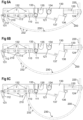
- FIGS 6A to 6C accordingly show the cable management system in various possible forms of application.
- different variations are shown for how the cable support 200 can be attached differently to the first lever 110.
- the embodiment of the cable support 200 can be seen more clearly in these views.
- a plurality of parallel slots 232 are provided in the central region 230 on the outer side of the cable support 200, i.e. a side facing away from the support mechanism, which slots are preferably evenly spaced. With reference to Figure 1 , these slots preferably extend along the full length of the cable support, but do not penetrate the cable support 200.
- the cable support 200 is formed, for example, from a rigid material, in particular a material that is resistant to bending, which ensures a high degree of stability but basically permits uniform bending.
- the slots 232 in the central region 230 allow the cable support 200 to be rolled up in the transverse direction as shown, but nevertheless do not permit bending or the like in the longitudinal direction, i.e. perpendicular to the major axis of the mounting mechanisms.
- the edge regions 210, 220 are designed without slots and are accordingly rigid.
- the material chosen is, for example, a felt material, in particular a plastic felt material.
- Other embodiments of the cable support 200 are not excluded, as long as, for example, longitudinal stability is provided with concurrent flexibility in the transverse direction. This can be achieved, for example, by lamellar or link structures in which the cable support 200 is formed from several individual parts, or similar embodiments.
- the second edge portion 220 is accommodated in the second retaining portion 124, as in Figure 1 .
- the position of the first edge region 210 on the first lever 110 varies in the different figures.
- the cable support 200 or the first edge portion 210 is received in an outer retaining portion 113 of the first lever 110, providing a small volume for receiving cables or other objects on the cable support 200.
- the first edge portion 210 is received in a central retaining portion 113 of the first lever 110, providing a medium volume for receiving cables and the like.
- the portion of the edge portion 210 that extends beyond the corresponding retaining portion 113 on the first lever 110 extends into a corresponding recess 132 in the base body 130.
- the various retaining positions 113 provide flexibility for the user of the cable management system, as the volume for holding cables and the like on the cable support 200 can be varied according to the needs of the user or the application. While in the embodiment shown there are three different holding positions for the cable support on the first lever, this number can also be varied as desired. In principle, it is possible for only one retaining portion to be provided on the first lever 110, but it is also possible to provide two or four or more retaining portions, depending on the application.
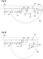
- Figures 7A and 7B illustrate the cable management system in conjunction with a worktop 300 in two different possible configurations, between which it is readily possible to switch during operation.
- an attachment of the support mechanism 100 or the base body 130 to the worktop remains unchanged.
- the first edge portion 10 is located in the central retaining portion of the first lever 110.
- the second lever 120 with its pivot mechanism 121 is supported in the second pivot point 134 and rests on the fixation point 136.
- the second lever 120 is nearly parallel to the surface of the countertop 300 and extends beyond the edge of the worktop 300.
- the second edge portion 220 is received in the second lever 120 such that the top edge of the cable support 200 is more or less flush with the top edge of the worktop 300. This provides both an improved appearance and ease of routing cables from the cable support area to the worktop 300.
- the second lever 120 with its pivot mechanism 121 is received in the third pivot point 135, which is located further inward with respect to the edge of the table.
- the second lever 120 rests on the third fixation point 137.
- the second lever 120 is no longer parallel to the surface of the worktop 300, but is inclined downwards to a certain degree. The inward positioning of the pivot point in conjunction with the greater inclination results in the second lever 120 and the second end region 220 being located completely below the worktop 300.
- Figures 8A and 8B illustrate various operating conditions of the cable management system in an example configuration.
- the first lever 110 is movably or pivotally mounted in the first pivot point 133, while the second lever 120 with its pivot mechanism 121 is mounted in the second pivot point 134.
- the cable support 200 is received on the first lever 110 in the central retaining position, as also shown, for example, in Figure 6B .
- the other retaining positions on the first lever 110 can of course be selected alternatively.
- the second lever 120 is engaged, i.e. rests on the fixation point.
- the first lever 110 is in an open position, i.e. not fixed, so that the cable support 200 is accessible from the first, inner side.
- Figure 9 shows an exemplary embodiment of a workstation system with a worktop 300 mounted on a table frame 310 and a cable management system according to one of the embodiments described above, of which only the cable support 200 is visible for illustration reasons.
- the cable management system is shown in an "over the edge" configuration, which was explained in more detail in connection with Figure 7A .
- Exemplary components on the workstation system are shown to illustrate the possible routing of cables into the cable management system, such as a monitor 320, a notebook computer 330, a keyboard 340, a workstation lamp 350, and a multiple socket outlet 360.
- the ability to open the cable management system from both sides allows for flexibility in use, even in different configurations of the workstation. For example, if the workstation is positioned with the second side, i.e. the side to which the second lever is directed, against the wall, there still remains the possibility to reach the cable support by opening the first side. In the case of a freestanding workstation, it may be more convenient to perform the opening of the cable management system via the second lever, so as not to use the access from the first side below the worktop.
- the cable management system offers visually appealing organization of the cables in each case.
- flexible functionality is also provided for widely varying "cable densities" at the table, for example, by adjusting the capacity of the cable stowage, which enables use both at a CAD workstation as one extreme example and with a tablet as another extreme example.
- the cables are secured against getting caught on obstacles.
- the cable management system in the embodiments described also enables easy assembly of the system. Operation, in particular accessibility and convenience of cable stowage, is also provided in all embodiments.
Landscapes
- Engineering & Computer Science (AREA)
- General Engineering & Computer Science (AREA)
- Mechanical Engineering (AREA)
- Architecture (AREA)
- Civil Engineering (AREA)
- Structural Engineering (AREA)
- Installation Of Indoor Wiring (AREA)
- Electric Cable Arrangement Between Relatively Moving Parts (AREA)
Claims (14)
- Kabelmanagementsystem für eine Arbeitsplatte (300), das Kabelmanagementsystem aufweisend einen Kabelträger (200), insbesondere flächigen Kabelträger (200), und wenigstens einen Trägermechanismus (100, 100'), der einen Grundkörper (130), einen ersten Hebel (110) und einen zweiten Hebel (120) umfasst, wobei- der Grundkörper (130) länglich zwischen einem ersten Ende und einem zweiten Ende entlang einer Hauptachse ausgebildet ist und eine erste Drehstelle (133) für den ersten Hebel (110), eine zweite Drehstelle (134) für den zweiten Hebel (120), eine erste Fixierstelle (131) für den ersten Hebel und eine zweite Fixierstelle (136) für den zweiten Hebel umfasst;- der erste Hebel (110) an einem proximalen Ende drehbar in der ersten Drehstelle (133) gelagert ist, wenigstens einen ersten Haltebereich (113) zur Aufnahme des Kabelträgers (200) aufweist und an der ersten Fixierstelle (131) fixierbar ist; und- der zweite Hebel (120) an einem proximalen Ende drehbar in der zweiten Drehstelle (134) lagerbar ist, wenigstens einen zweiten Haltebereich (124) zur Aufnahme des Kabelträgers (200) aufweist und an der zweiten Fixierstelle (136) fixierbar ist;
gekennzeichnet dadurch, dass- die proximalen Enden des ersten und zweiten Hebels einander zugewandt sind;- ein distales Ende des ersten Hebels dem ersten Ende des Grundkörpers zugewandt ist; und- ein distales Ende des zweiten Hebels dem zweiten Ende des Grundkörpers zugewandt ist. - Kabelmanagementsystem nach Anspruch 1, wobei der erste Hebel (110) wenigstens einen weiteren Haltebereich zur Aufnahme des Kabelträgers (200) aufweist, der beabstandet zum ersten Haltebereich ist.
- Kabelmanagementsystem nach Anspruch 1 oder 2, wobei der erste und, falls vorhanden, der wenigstens eine weitere Haltebereich (113) wenigstens einen Stopper (114) aufweisen, der für ein Verhindern eines Verschiebens des Kabelträgers (200) am ersten Hebel eingerichtet ist.
- Kabelmanagementsystem nach einem der Ansprüche 1 bis 3, wobei der Grundkörper (130) im fixierten Zustand des ersten Hebels (110) im Bereich des ersten und, falls vorhanden, des wenigstens einen weiteren Haltebereichs (113) eine jeweilige Ausnehmung (132) aufweist.
- Kabelmanagementsystem nach einem der Ansprüche 1 bis 4, wobei die erste Fixierstelle am Grundkörper (130) durch einen ersten Teil einer ersten Haltevorrichtung, insbesondere Schnappvorrichtung, gebildet ist und das distale Ende des ersten Hebels einen zweiten Teil (112) der ersten Haltevorrichtung aufweist.
- Kabelmanagementsystem nach einem der Ansprüche 1 bis 5, wobei die zweite Fixierstelle am Grundkörper (130) durch ein Auflager gebildet ist und der zweite Hebel (120) einen flexiblen Teil aufweist, der eingerichtet ist, in einem Ruhezustand des zweiten Hebels auf dem Auflager aufzuliegen und in einem Entriegelungszustand ein Aufliegen auf dem Auflager zu verhindern.
- Kabelmanagementsystem nach einem der Ansprüche 1 bis 6, wobei der Kabelträger (200) in einem Randbereich (210, 220) eine oder mehrere Öffnungen (212, 222) zur Aufnahme des ersten und/oder zweiten Hebels aufweist.
- Kabelmanagementsystem nach einem der Ansprüche 1 bis 7, wobei der Kabelträger (200) aus einem steifen, insbesondere biegefesten, Material gebildet ist und in einem Zentralbereich (230) eine Vielzahl paralleler Schlitze (232) aufweist, die senkrecht oder im Wesentlichen senkrecht zur Hauptachse ausgerichtet sind.
- Kabelmanagementsystem nach einem der Ansprüche 1 bis 8, wobei der Grundkörper (130) eine Befestigungsanordnung (138) zum Befestigen des Trägermechanismus (100, 100') an der Arbeitsplatte (300) aufweist.
- Kabelmanagementsystem nach einem der Ansprüche 1 bis 9, umfassend wenigstens zwei Trägermechanismen (100, 100'), insbesondere identisch aufgebaute Trägermechanismen (100, 100').
- Kabelmanagementsystem nach einem der Ansprüche 1 bis 10, wobei der Grundkörper (130) eine dritte Drehstelle (135) für den zweiten Hebel und eine dritte Fixierstelle (137) für den zweiten Hebel umfasst, sodass der zweite Hebel (120) an dem proximalen Ende drehbar in der dritten Drehstelle (135) lagerbar ist.
- Kabelmanagementsystem nach Anspruch 11, wobei ein Winkel zwischen der Hauptachse und einer Verbindung der zweiten Drehstelle und der zweiten Fixierstelle unterschiedlich ist zu einem Winkel zwischen der Hauptachse und einer Verbindung der dritten Drehstelle und der dritten Fixierstelle.
- Arbeitsplatzsystem mit einer Arbeitsplatte (300) und einem an der Arbeitsplatte (300) befestigten Kabelmanagementsystem nach einem der vorangehenden Ansprüche.
- Arbeitsplatzsystem nach Anspruch 13, bei dem das Kabelmanagementsystem nach einem der Ansprüche 11 oder 12 ausgeführt ist, wobei- der zweite Hebel (120) in einer ersten und einer zweiten Konfiguration nutzbar ist;- in der ersten Konfiguration der zweite Hebel (120) in der zweiten Drehstelle (134) gelagert ist und bei einer Fixierung des zweiten Hebels an der zweiten Fixierstelle (136) der Kabelträger (200) über eine seitliche Kante der Arbeitsplatte (300) herausragt; und- in der zweiten Konfiguration der zweite Hebel (120) in der dritten Drehstelle (135) gelagert ist und bei einer Fixierung des zweiten Hebels an der dritten Fixierstelle (137) der Kabelträger (200) sich unterhalb der Arbeitsplatte (300) befindet.
Applications Claiming Priority (1)
| Application Number | Priority Date | Filing Date | Title |
|---|---|---|---|
| DE102020112989.0A DE102020112989B4 (de) | 2020-05-13 | 2020-05-13 | Kabelmanagementsystem und Arbeitsplatzsystem |
Publications (4)
| Publication Number | Publication Date |
|---|---|
| EP3909467A1 EP3909467A1 (de) | 2021-11-17 |
| EP3909467B1 true EP3909467B1 (de) | 2024-04-24 |
| EP3909467C0 EP3909467C0 (de) | 2024-04-24 |
| EP3909467B8 EP3909467B8 (de) | 2024-07-10 |
Family
ID=75887926
Family Applications (1)
| Application Number | Title | Priority Date | Filing Date |
|---|---|---|---|
| EP21173053.6A Active EP3909467B8 (de) | 2020-05-13 | 2021-05-10 | Kabelverwaltungssystem und arbeitsplatzsystem |
Country Status (3)
| Country | Link |
|---|---|
| US (1) | US11638478B2 (de) |
| EP (1) | EP3909467B8 (de) |
| DE (1) | DE102020112989B4 (de) |
Families Citing this family (4)
| Publication number | Priority date | Publication date | Assignee | Title |
|---|---|---|---|---|
| US12144418B2 (en) * | 2019-10-29 | 2024-11-19 | Miller Knoll, Inc. | Table with wire management system |
| US11855432B2 (en) * | 2021-08-31 | 2023-12-26 | Quanta Computer Inc. | Cable management brackets |
| USD1056675S1 (en) * | 2022-06-28 | 2025-01-07 | Chih-Chien Hsieh | Fastening buckle for socket rail organizer tray |
| WO2025259298A1 (en) * | 2024-06-11 | 2025-12-18 | Workrite Ergonomics, Llc | Cable manager device and cable management system using same |
Family Cites Families (13)
| Publication number | Priority date | Publication date | Assignee | Title |
|---|---|---|---|---|
| DE3634999A1 (de) | 1986-10-14 | 1988-04-21 | Werndl Wilhelm Gmbh & Co Kg | Verschwenkverbindung |
| US5669590A (en) * | 1995-12-04 | 1997-09-23 | Yazaki Corporation | Retaining clip with multiple clamps |
| ES2296255T3 (es) | 2000-09-11 | 2008-04-16 | Zipher Limited | Accionador de cinta y maquina impresora. |
| US7345241B2 (en) * | 2005-01-18 | 2008-03-18 | Panduit Corp. | Cable management support bar with strain relief clamps |
| DE202006007424U1 (de) * | 2006-05-09 | 2006-07-27 | Steelcase Werndl Ag | Möbel mit Kabelkanal |
| US8056868B2 (en) * | 2007-08-17 | 2011-11-15 | Paccar Inc | Conduit for vehicle system components |
| DE202008013987U1 (de) | 2008-10-20 | 2010-03-04 | VS Vereinigte Spezialmöbelfabriken GmbH & Co. KG | Tischmöbel mit Kabelkanalvorrichtung |
| DE202010005840U1 (de) * | 2010-04-19 | 2010-08-12 | Vitra Patente Ag | Kabelführung an einem höhenverstellbaren Tisch |
| US8634198B2 (en) * | 2011-07-01 | 2014-01-21 | King Slide Works Co., Ltd. | Connection device of cable management arm |
| US9038247B2 (en) * | 2013-01-03 | 2015-05-26 | Benjamin Dodge | Rope clasp |
| US9581270B2 (en) * | 2014-11-12 | 2017-02-28 | Te Connectivity Corporation | Wire tray for a wire harness assembly |
| PT3729579T (pt) * | 2017-12-21 | 2025-07-10 | Jehier | Conjunto comportando um cabo e um suporte para esse cabo |
| DE202019100434U1 (de) * | 2019-01-25 | 2019-06-03 | Igus Gmbh | Quersteg und Kettenglied mit Quersteg |
-
2020
- 2020-05-13 DE DE102020112989.0A patent/DE102020112989B4/de not_active Expired - Fee Related
-
2021
- 2021-05-10 EP EP21173053.6A patent/EP3909467B8/de active Active
- 2021-05-12 US US17/318,216 patent/US11638478B2/en active Active
Also Published As
| Publication number | Publication date |
|---|---|
| DE102020112989B4 (de) | 2024-03-07 |
| DE102020112989A1 (de) | 2021-11-18 |
| EP3909467A1 (de) | 2021-11-17 |
| EP3909467B8 (de) | 2024-07-10 |
| EP3909467C0 (de) | 2024-04-24 |
| US20210353050A1 (en) | 2021-11-18 |
| US11638478B2 (en) | 2023-05-02 |
Similar Documents
| Publication | Publication Date | Title |
|---|---|---|
| EP3909467B1 (de) | Kabelverwaltungssystem und arbeitsplatzsystem | |
| US6732661B2 (en) | Moving table flap | |
| US7757612B2 (en) | Convertible workstation | |
| US6805248B2 (en) | Electrical equipment rack and cable management arm assembly | |
| US10113691B2 (en) | Stabilising device | |
| US6726164B1 (en) | Mounting bracket having a tapered plunger latch | |
| US6665175B1 (en) | Computer having a monitor that has multiple degrees of freedom with respect to the base of the computer | |
| RU2410006C2 (ru) | Мебель с кабельным каналом | |
| US7857401B2 (en) | Anti-tip interlocking linkage mechanism for vertical cabinets | |
| JP4426143B2 (ja) | 引き出しスライド用の調整可能な移動止め機構 | |
| EP0495290A1 (de) | Eine lösbare zweiseitige Scharniervorrichtung für einen Konsolenkasten eines Fahrzeuges | |
| EP1703702A1 (de) | Klappbares und tragbares Funkkommunikationsgerät mit einem doppelwirkenden Gelenk | |
| EP2448447A1 (de) | Träger für eine rekonfigurierbare arbeitsstation | |
| EP1710985B1 (de) | Verschiebbares und mobiles Endgerät | |
| KR20040061122A (ko) | 힌지장치 및 이를 장착한 전기전자장치 | |
| WO2000045011A1 (en) | Swiveling computer peripheral support assembly | |
| AU2017356632A1 (en) | Battery receiving area | |
| CN109891694B (zh) | 包括用于附接轨道的锁定装置的电气设备 | |
| US20050212772A1 (en) | Foldable keyboard | |
| CN223137459U (zh) | 一种收纳支架 | |
| KR100863980B1 (ko) | 컴퓨터 주변기기 및 본체 수납용 캐비닛 | |
| US20050099396A1 (en) | Foldable keyboard | |
| KR200280113Y1 (ko) | 키보드 트레이 | |
| KR19990066879A (ko) | 컴퓨터 및 전자통신 기구를 포함하는 장치 | |
| KR0131711Y1 (ko) | 노트북 컴퓨터의 키보드장치 |
Legal Events
| Date | Code | Title | Description |
|---|---|---|---|
| PUAI | Public reference made under article 153(3) epc to a published international application that has entered the european phase |
Free format text: ORIGINAL CODE: 0009012 |
|
| STAA | Information on the status of an ep patent application or granted ep patent |
Free format text: STATUS: THE APPLICATION HAS BEEN PUBLISHED |
|
| AK | Designated contracting states |
Kind code of ref document: A1 Designated state(s): AL AT BE BG CH CY CZ DE DK EE ES FI FR GB GR HR HU IE IS IT LI LT LU LV MC MK MT NL NO PL PT RO RS SE SI SK SM TR |
|
| B565 | Issuance of search results under rule 164(2) epc |
Effective date: 20211013 |
|
| STAA | Information on the status of an ep patent application or granted ep patent |
Free format text: STATUS: REQUEST FOR EXAMINATION WAS MADE |
|
| 17P | Request for examination filed |
Effective date: 20211214 |
|
| RBV | Designated contracting states (corrected) |
Designated state(s): AL AT BE BG CH CY CZ DE DK EE ES FI FR GB GR HR HU IE IS IT LI LT LU LV MC MK MT NL NO PL PT RO RS SE SI SK SM TR |
|
| RAP1 | Party data changed (applicant data changed or rights of an application transferred) |
Owner name: YAASA GMBH |
|
| GRAP | Despatch of communication of intention to grant a patent |
Free format text: ORIGINAL CODE: EPIDOSNIGR1 |
|
| STAA | Information on the status of an ep patent application or granted ep patent |
Free format text: STATUS: GRANT OF PATENT IS INTENDED |
|
| INTG | Intention to grant announced |
Effective date: 20240110 |
|
| GRAS | Grant fee paid |
Free format text: ORIGINAL CODE: EPIDOSNIGR3 |
|
| GRAA | (expected) grant |
Free format text: ORIGINAL CODE: 0009210 |
|
| STAA | Information on the status of an ep patent application or granted ep patent |
Free format text: STATUS: THE PATENT HAS BEEN GRANTED |
|
| AK | Designated contracting states |
Kind code of ref document: B1 Designated state(s): AL AT BE BG CH CY CZ DE DK EE ES FI FR GB GR HR HU IE IS IT LI LT LU LV MC MK MT NL NO PL PT RO RS SE SI SK SM TR |
|
| REG | Reference to a national code |
Ref country code: GB Ref legal event code: FG4D |
|
| REG | Reference to a national code |
Ref country code: CH Ref legal event code: EP |
|
| REG | Reference to a national code |
Ref country code: DE Ref legal event code: R096 Ref document number: 602021012129 Country of ref document: DE |
|
| REG | Reference to a national code |
Ref country code: IE Ref legal event code: FG4D |
|
| RAP4 | Party data changed (patent owner data changed or rights of a patent transferred) |
Owner name: YAASA GMBH |
|
| U01 | Request for unitary effect filed |
Effective date: 20240429 |
|
| U07 | Unitary effect registered |
Designated state(s): AT BE BG DE DK EE FI FR IT LT LU LV MT NL PT SE SI Effective date: 20240507 |
|
| REG | Reference to a national code |
Ref country code: CH Ref legal event code: PK Free format text: BERICHTIGUNG B8 |
|
| U20 | Renewal fee for the european patent with unitary effect paid |
Year of fee payment: 4 Effective date: 20240527 |
|
| PG25 | Lapsed in a contracting state [announced via postgrant information from national office to epo] |
Ref country code: IS Free format text: LAPSE BECAUSE OF FAILURE TO SUBMIT A TRANSLATION OF THE DESCRIPTION OR TO PAY THE FEE WITHIN THE PRESCRIBED TIME-LIMIT Effective date: 20240824 |
|
| PG25 | Lapsed in a contracting state [announced via postgrant information from national office to epo] |
Ref country code: HR Free format text: LAPSE BECAUSE OF FAILURE TO SUBMIT A TRANSLATION OF THE DESCRIPTION OR TO PAY THE FEE WITHIN THE PRESCRIBED TIME-LIMIT Effective date: 20240424 |
|
| PG25 | Lapsed in a contracting state [announced via postgrant information from national office to epo] |
Ref country code: GR Free format text: LAPSE BECAUSE OF FAILURE TO SUBMIT A TRANSLATION OF THE DESCRIPTION OR TO PAY THE FEE WITHIN THE PRESCRIBED TIME-LIMIT Effective date: 20240725 |
|
| PG25 | Lapsed in a contracting state [announced via postgrant information from national office to epo] |
Ref country code: ES Free format text: LAPSE BECAUSE OF FAILURE TO SUBMIT A TRANSLATION OF THE DESCRIPTION OR TO PAY THE FEE WITHIN THE PRESCRIBED TIME-LIMIT Effective date: 20240424 |
|
| PG25 | Lapsed in a contracting state [announced via postgrant information from national office to epo] |
Ref country code: PL Free format text: LAPSE BECAUSE OF FAILURE TO SUBMIT A TRANSLATION OF THE DESCRIPTION OR TO PAY THE FEE WITHIN THE PRESCRIBED TIME-LIMIT Effective date: 20240424 |
|
| PG25 | Lapsed in a contracting state [announced via postgrant information from national office to epo] |
Ref country code: PL Free format text: LAPSE BECAUSE OF FAILURE TO SUBMIT A TRANSLATION OF THE DESCRIPTION OR TO PAY THE FEE WITHIN THE PRESCRIBED TIME-LIMIT Effective date: 20240424 Ref country code: NO Free format text: LAPSE BECAUSE OF FAILURE TO SUBMIT A TRANSLATION OF THE DESCRIPTION OR TO PAY THE FEE WITHIN THE PRESCRIBED TIME-LIMIT Effective date: 20240724 Ref country code: IS Free format text: LAPSE BECAUSE OF FAILURE TO SUBMIT A TRANSLATION OF THE DESCRIPTION OR TO PAY THE FEE WITHIN THE PRESCRIBED TIME-LIMIT Effective date: 20240824 Ref country code: HR Free format text: LAPSE BECAUSE OF FAILURE TO SUBMIT A TRANSLATION OF THE DESCRIPTION OR TO PAY THE FEE WITHIN THE PRESCRIBED TIME-LIMIT Effective date: 20240424 Ref country code: GR Free format text: LAPSE BECAUSE OF FAILURE TO SUBMIT A TRANSLATION OF THE DESCRIPTION OR TO PAY THE FEE WITHIN THE PRESCRIBED TIME-LIMIT Effective date: 20240725 Ref country code: ES Free format text: LAPSE BECAUSE OF FAILURE TO SUBMIT A TRANSLATION OF THE DESCRIPTION OR TO PAY THE FEE WITHIN THE PRESCRIBED TIME-LIMIT Effective date: 20240424 Ref country code: RS Free format text: LAPSE BECAUSE OF FAILURE TO SUBMIT A TRANSLATION OF THE DESCRIPTION OR TO PAY THE FEE WITHIN THE PRESCRIBED TIME-LIMIT Effective date: 20240724 |
|
| PG25 | Lapsed in a contracting state [announced via postgrant information from national office to epo] |
Ref country code: CZ Free format text: LAPSE BECAUSE OF FAILURE TO SUBMIT A TRANSLATION OF THE DESCRIPTION OR TO PAY THE FEE WITHIN THE PRESCRIBED TIME-LIMIT Effective date: 20240424 |
|
| PG25 | Lapsed in a contracting state [announced via postgrant information from national office to epo] |
Ref country code: SK Free format text: LAPSE BECAUSE OF FAILURE TO SUBMIT A TRANSLATION OF THE DESCRIPTION OR TO PAY THE FEE WITHIN THE PRESCRIBED TIME-LIMIT Effective date: 20240424 Ref country code: RO Free format text: LAPSE BECAUSE OF FAILURE TO SUBMIT A TRANSLATION OF THE DESCRIPTION OR TO PAY THE FEE WITHIN THE PRESCRIBED TIME-LIMIT Effective date: 20240424 |
|
| REG | Reference to a national code |
Ref country code: DE Ref legal event code: R097 Ref document number: 602021012129 Country of ref document: DE |
|
| PG25 | Lapsed in a contracting state [announced via postgrant information from national office to epo] |
Ref country code: SM Free format text: LAPSE BECAUSE OF FAILURE TO SUBMIT A TRANSLATION OF THE DESCRIPTION OR TO PAY THE FEE WITHIN THE PRESCRIBED TIME-LIMIT Effective date: 20240424 |
|
| PG25 | Lapsed in a contracting state [announced via postgrant information from national office to epo] |
Ref country code: SM Free format text: LAPSE BECAUSE OF FAILURE TO SUBMIT A TRANSLATION OF THE DESCRIPTION OR TO PAY THE FEE WITHIN THE PRESCRIBED TIME-LIMIT Effective date: 20240424 Ref country code: SK Free format text: LAPSE BECAUSE OF FAILURE TO SUBMIT A TRANSLATION OF THE DESCRIPTION OR TO PAY THE FEE WITHIN THE PRESCRIBED TIME-LIMIT Effective date: 20240424 Ref country code: RO Free format text: LAPSE BECAUSE OF FAILURE TO SUBMIT A TRANSLATION OF THE DESCRIPTION OR TO PAY THE FEE WITHIN THE PRESCRIBED TIME-LIMIT Effective date: 20240424 Ref country code: CZ Free format text: LAPSE BECAUSE OF FAILURE TO SUBMIT A TRANSLATION OF THE DESCRIPTION OR TO PAY THE FEE WITHIN THE PRESCRIBED TIME-LIMIT Effective date: 20240424 Ref country code: MC Free format text: LAPSE BECAUSE OF FAILURE TO SUBMIT A TRANSLATION OF THE DESCRIPTION OR TO PAY THE FEE WITHIN THE PRESCRIBED TIME-LIMIT Effective date: 20240424 |
|
| PLBE | No opposition filed within time limit |
Free format text: ORIGINAL CODE: 0009261 |
|
| STAA | Information on the status of an ep patent application or granted ep patent |
Free format text: STATUS: NO OPPOSITION FILED WITHIN TIME LIMIT |
|
| 26N | No opposition filed |
Effective date: 20250127 |
|
| PG25 | Lapsed in a contracting state [announced via postgrant information from national office to epo] |
Ref country code: IE Free format text: LAPSE BECAUSE OF NON-PAYMENT OF DUE FEES Effective date: 20240510 |
|
| U20 | Renewal fee for the european patent with unitary effect paid |
Year of fee payment: 5 Effective date: 20250522 |
|
| PGFP | Annual fee paid to national office [announced via postgrant information from national office to epo] |
Ref country code: CH Payment date: 20250601 Year of fee payment: 5 |
|
| PG25 | Lapsed in a contracting state [announced via postgrant information from national office to epo] |
Ref country code: CY Free format text: LAPSE BECAUSE OF FAILURE TO SUBMIT A TRANSLATION OF THE DESCRIPTION OR TO PAY THE FEE WITHIN THE PRESCRIBED TIME-LIMIT; INVALID AB INITIO Effective date: 20210510 |
|
| PG25 | Lapsed in a contracting state [announced via postgrant information from national office to epo] |
Ref country code: HU Free format text: LAPSE BECAUSE OF FAILURE TO SUBMIT A TRANSLATION OF THE DESCRIPTION OR TO PAY THE FEE WITHIN THE PRESCRIBED TIME-LIMIT; INVALID AB INITIO Effective date: 20210510 |
|
| GBPC | Gb: european patent ceased through non-payment of renewal fee |
Effective date: 20250510 |