EP3908543B1 - Procédé d'alimentation en matières solides d'un dispositif de mélange, dispositif d'alimentation en matières solides et dispositif de mélange - Google Patents
Procédé d'alimentation en matières solides d'un dispositif de mélange, dispositif d'alimentation en matières solides et dispositif de mélange Download PDFInfo
- Publication number
- EP3908543B1 EP3908543B1 EP20700777.4A EP20700777A EP3908543B1 EP 3908543 B1 EP3908543 B1 EP 3908543B1 EP 20700777 A EP20700777 A EP 20700777A EP 3908543 B1 EP3908543 B1 EP 3908543B1
- Authority
- EP
- European Patent Office
- Prior art keywords
- solid material
- mixing
- solids
- slide
- outlet
- Prior art date
- Legal status (The legal status is an assumption and is not a legal conclusion. Google has not performed a legal analysis and makes no representation as to the accuracy of the status listed.)
- Active
Links
- 238000000034 method Methods 0.000 title claims description 24
- 239000011343 solid material Substances 0.000 title claims 53
- 239000007787 solid Substances 0.000 claims description 234
- 239000000843 powder Substances 0.000 claims description 19
- 238000012544 monitoring process Methods 0.000 claims description 17
- 239000007788 liquid Substances 0.000 claims description 9
- 239000013590 bulk material Substances 0.000 claims description 6
- 230000008859 change Effects 0.000 claims description 4
- -1 for example Substances 0.000 claims 2
- 230000003213 activating effect Effects 0.000 claims 1
- 230000004913 activation Effects 0.000 claims 1
- 238000001514 detection method Methods 0.000 claims 1
- 238000012806 monitoring device Methods 0.000 description 17
- 238000005276 aerator Methods 0.000 description 3
- 239000000463 material Substances 0.000 description 3
- 230000009467 reduction Effects 0.000 description 3
- GWEVSGVZZGPLCZ-UHFFFAOYSA-N Titan oxide Chemical compound O=[Ti]=O GWEVSGVZZGPLCZ-UHFFFAOYSA-N 0.000 description 2
- 230000008901 benefit Effects 0.000 description 2
- 239000000203 mixture Substances 0.000 description 2
- 238000009825 accumulation Methods 0.000 description 1
- 239000011248 coating agent Substances 0.000 description 1
- 238000000576 coating method Methods 0.000 description 1
- 239000012530 fluid Substances 0.000 description 1
- 239000008187 granular material Substances 0.000 description 1
- 230000008569 process Effects 0.000 description 1
- 230000035939 shock Effects 0.000 description 1
- 238000003756 stirring Methods 0.000 description 1
- 239000004408 titanium dioxide Substances 0.000 description 1
- 238000011144 upstream manufacturing Methods 0.000 description 1
Images

Classifications
-
- B—PERFORMING OPERATIONS; TRANSPORTING
- B01—PHYSICAL OR CHEMICAL PROCESSES OR APPARATUS IN GENERAL
- B01F—MIXING, e.g. DISSOLVING, EMULSIFYING OR DISPERSING
- B01F35/00—Accessories for mixers; Auxiliary operations or auxiliary devices; Parts or details of general application
- B01F35/10—Maintenance of mixers
- B01F35/12—Maintenance of mixers using mechanical means
- B01F35/122—Maintenance of mixers using mechanical means using pushers, i.e. a piston, for pushing out rests of products
-
- B—PERFORMING OPERATIONS; TRANSPORTING
- B01—PHYSICAL OR CHEMICAL PROCESSES OR APPARATUS IN GENERAL
- B01F—MIXING, e.g. DISSOLVING, EMULSIFYING OR DISPERSING
- B01F23/00—Mixing according to the phases to be mixed, e.g. dispersing or emulsifying
- B01F23/50—Mixing liquids with solids
- B01F23/53—Mixing liquids with solids using driven stirrers
-
- B—PERFORMING OPERATIONS; TRANSPORTING
- B01—PHYSICAL OR CHEMICAL PROCESSES OR APPARATUS IN GENERAL
- B01F—MIXING, e.g. DISSOLVING, EMULSIFYING OR DISPERSING
- B01F23/00—Mixing according to the phases to be mixed, e.g. dispersing or emulsifying
- B01F23/50—Mixing liquids with solids
- B01F23/59—Mixing systems, i.e. flow charts or diagrams
-
- B—PERFORMING OPERATIONS; TRANSPORTING
- B01—PHYSICAL OR CHEMICAL PROCESSES OR APPARATUS IN GENERAL
- B01F—MIXING, e.g. DISSOLVING, EMULSIFYING OR DISPERSING
- B01F27/00—Mixers with rotary stirring devices in fixed receptacles; Kneaders
- B01F27/27—Mixers with stator-rotor systems, e.g. with intermeshing teeth or cylinders or having orifices
- B01F27/271—Mixers with stator-rotor systems, e.g. with intermeshing teeth or cylinders or having orifices with means for moving the materials to be mixed radially between the surfaces of the rotor and the stator
-
- B—PERFORMING OPERATIONS; TRANSPORTING
- B01—PHYSICAL OR CHEMICAL PROCESSES OR APPARATUS IN GENERAL
- B01F—MIXING, e.g. DISSOLVING, EMULSIFYING OR DISPERSING
- B01F35/00—Accessories for mixers; Auxiliary operations or auxiliary devices; Parts or details of general application
- B01F35/20—Measuring; Control or regulation
- B01F35/21—Measuring
- B01F35/211—Measuring of the operational parameters
- B01F35/2113—Pressure
-
- B—PERFORMING OPERATIONS; TRANSPORTING
- B01—PHYSICAL OR CHEMICAL PROCESSES OR APPARATUS IN GENERAL
- B01F—MIXING, e.g. DISSOLVING, EMULSIFYING OR DISPERSING
- B01F35/00—Accessories for mixers; Auxiliary operations or auxiliary devices; Parts or details of general application
- B01F35/20—Measuring; Control or regulation
- B01F35/21—Measuring
- B01F35/212—Measuring of the driving system data, e.g. torque, speed or power data
-
- B—PERFORMING OPERATIONS; TRANSPORTING
- B01—PHYSICAL OR CHEMICAL PROCESSES OR APPARATUS IN GENERAL
- B01F—MIXING, e.g. DISSOLVING, EMULSIFYING OR DISPERSING
- B01F35/00—Accessories for mixers; Auxiliary operations or auxiliary devices; Parts or details of general application
- B01F35/71—Feed mechanisms
- B01F35/717—Feed mechanisms characterised by the means for feeding the components to the mixer
- B01F35/7173—Feed mechanisms characterised by the means for feeding the components to the mixer using gravity, e.g. from a hopper
- B01F35/71731—Feed mechanisms characterised by the means for feeding the components to the mixer using gravity, e.g. from a hopper using a hopper
-
- B—PERFORMING OPERATIONS; TRANSPORTING
- B01—PHYSICAL OR CHEMICAL PROCESSES OR APPARATUS IN GENERAL
- B01F—MIXING, e.g. DISSOLVING, EMULSIFYING OR DISPERSING
- B01F35/00—Accessories for mixers; Auxiliary operations or auxiliary devices; Parts or details of general application
- B01F35/71—Feed mechanisms
- B01F35/717—Feed mechanisms characterised by the means for feeding the components to the mixer
- B01F35/718—Feed mechanisms characterised by the means for feeding the components to the mixer using vacuum, under pressure in a closed receptacle or circuit system
-
- B—PERFORMING OPERATIONS; TRANSPORTING
- B65—CONVEYING; PACKING; STORING; HANDLING THIN OR FILAMENTARY MATERIAL
- B65G—TRANSPORT OR STORAGE DEVICES, e.g. CONVEYORS FOR LOADING OR TIPPING, SHOP CONVEYOR SYSTEMS OR PNEUMATIC TUBE CONVEYORS
- B65G43/00—Control devices, e.g. for safety, warning or fault-correcting
-
- B—PERFORMING OPERATIONS; TRANSPORTING
- B65—CONVEYING; PACKING; STORING; HANDLING THIN OR FILAMENTARY MATERIAL
- B65G—TRANSPORT OR STORAGE DEVICES, e.g. CONVEYORS FOR LOADING OR TIPPING, SHOP CONVEYOR SYSTEMS OR PNEUMATIC TUBE CONVEYORS
- B65G47/00—Article or material-handling devices associated with conveyors; Methods employing such devices
- B65G47/02—Devices for feeding articles or materials to conveyors
- B65G47/16—Devices for feeding articles or materials to conveyors for feeding materials in bulk
- B65G47/18—Arrangements or applications of hoppers or chutes
- B65G47/19—Arrangements or applications of hoppers or chutes having means for controlling material flow, e.g. to prevent overloading
-
- B—PERFORMING OPERATIONS; TRANSPORTING
- B65—CONVEYING; PACKING; STORING; HANDLING THIN OR FILAMENTARY MATERIAL
- B65G—TRANSPORT OR STORAGE DEVICES, e.g. CONVEYORS FOR LOADING OR TIPPING, SHOP CONVEYOR SYSTEMS OR PNEUMATIC TUBE CONVEYORS
- B65G53/00—Conveying materials in bulk through troughs, pipes or tubes by floating the materials or by flow of gas, liquid or foam
- B65G53/34—Details
- B65G53/40—Feeding or discharging devices
- B65G53/46—Gates or sluices, e.g. rotary wheels
- B65G53/4683—Gates or sluices, e.g. rotary wheels with a reciprocating mover acting directly on material
-
- B—PERFORMING OPERATIONS; TRANSPORTING
- B65—CONVEYING; PACKING; STORING; HANDLING THIN OR FILAMENTARY MATERIAL
- B65G—TRANSPORT OR STORAGE DEVICES, e.g. CONVEYORS FOR LOADING OR TIPPING, SHOP CONVEYOR SYSTEMS OR PNEUMATIC TUBE CONVEYORS
- B65G53/00—Conveying materials in bulk through troughs, pipes or tubes by floating the materials or by flow of gas, liquid or foam
- B65G53/34—Details
- B65G53/52—Adaptations of pipes or tubes
- B65G53/521—Adaptations of pipes or tubes means for preventing the accumulation or for removal of deposits
-
- B—PERFORMING OPERATIONS; TRANSPORTING
- B01—PHYSICAL OR CHEMICAL PROCESSES OR APPARATUS IN GENERAL
- B01F—MIXING, e.g. DISSOLVING, EMULSIFYING OR DISPERSING
- B01F2101/00—Mixing characterised by the nature of the mixed materials or by the application field
- B01F2101/06—Mixing of food ingredients
-
- B—PERFORMING OPERATIONS; TRANSPORTING
- B01—PHYSICAL OR CHEMICAL PROCESSES OR APPARATUS IN GENERAL
- B01F—MIXING, e.g. DISSOLVING, EMULSIFYING OR DISPERSING
- B01F2101/00—Mixing characterised by the nature of the mixed materials or by the application field
- B01F2101/22—Mixing of ingredients for pharmaceutical or medical compositions
Definitions
- the invention relates to a method for feeding solids to a mixing device using a solids feeding device.
- the invention also relates to a solids feed device for feeding solids, in particular bulk material, such as powder, to a mixing device, the solids feed device having a hopper for receiving solids and a solids outlet which can be connected to a solids inlet of a mixing device, the solids outlet and the hopper are connected to each other via a conveyor connection.
- the invention also relates to a mixing arrangement with at least one mixing device and at least one solids supply device and the use of a solids supply device and/or a mixing arrangement in a method of the type mentioned at the outset.
- Solids supply devices are from practice and also from the printed state of the art, for example from the publications WO 2008/098706 A1 , EP 1 197 260 A1 , DE 10 2015 110 865 A1 , U.S. 1,974,789 A and JP 2013 035 030 A previously known in various embodiments. They are used to pick up solids, such as powder or granules, and feed them to a downstream mixing device.
- WO2008/098706A1 discloses the preamble of claims 1 and 4.
- mixing devices that are operated together with such solids feed devices in so-called mixing arrangements are often solid-liquid mixing devices that are used to introduce solids into a liquid and mix it with it as uniformly as possible mix.
- So-called suction lances, sack chutes or big-bag emptying stations are often used to feed the solids, i.e. to transfer the solids to the solids feed device.
- the solids are then fed to the downstream mixing devices with the aid of the solids feed devices.
- this feed is sometimes better or worse.
- the feed usually succeeds without any problems.
- the conveyor connection downstream of the hopper is generally not affected by the vibrations and shocks that are transmitted to the hopper by such knockers and vibrators.
- the supply of remains problematic Solids through the conveyor connection that is necessary between the hopper and the solids outlet of the solids feeder.
- the object of the invention is therefore to provide a method, a solids supply device and a mixing arrangement of the type mentioned at the outset which avoid the aforementioned problems and simplify the supply of solids.
- a method with the means and features of the independent claim directed to a method for feeding solids to a mixing device is first proposed.
- a method for feeding solids for example bulk material such as powder
- the solids feeding device comprises a hopper for receiving solids and a solids outlet which is connected to a solids inlet of the mixing device to which the solids are to be fed.
- the solids outlet and the hopper are connected to one another via a conveyor connection of the solids feed device.
- the solid is fed via the conveying connection to the mixing device, here in particular to a mixing chamber of the mixing device.
- the solids supply device has a slide which can be moved between a first end position and a second end position by the conveyor connection and is set up to buildup of solids within the to release the delivery connection. According to the invention, the slide is activated and moved through the conveyor connection to clear the conveyor connection as soon as the conveyor connection between the solids outlet and the hopper is blocked.
- Adhesion of solids that can become lodged within the conveyor connection of the solids feed device can thus be removed particularly easily and without dismantling the conveyor connection.
- One embodiment of the method provides for the solid to be conveyed, for example sucked, into the mixing device, here in particular into a mixing chamber of the mixing device, with the aid of negative pressure.
- the negative pressure with which the solids can be fed to the mixing device can be generated, for example, with a rotor-stator unit of the mixing device.
- the rotor-stator unit can be arranged in one, for example in the previously mentioned mixing chamber of the mixing device.
- the solid With the aid of the negative pressure, the solid can be sucked into the mixing chamber of the mixing device through the conveying connection of the solid supply device.
- a continuous pressure connection can be opened between the mixing chamber of the mixing device and the hopper of the solid supply device, which is not affected by the slide. Only in the event of a blockage in the conveyor connection is the slide activated and moved through the conveyor connection to clear the conveyor connection.
- blockages in the conveying connection are detected with a monitoring device.
- the monitoring device can be a monitoring device be solid feeder.
- the monitoring device activates the slide, in particular a slide drive of the solids feed device, at least indirectly as soon as a blockage of the conveyor connection is detected.
- the monitoring device can automatically activate the slide, in particular a slide drive, at least indirectly, causing the slide to be moved through the conveyor connection in order to loosen any blockages and free the conveyor connection from buildup.
- a blockage of the delivery connection can be detected based on a drop in power consumption of a drive of the rotor-stator unit of the mixing device.
- a monitoring sensor of the monitoring device it is also possible to use a monitoring sensor of the monitoring device to detect a blockage in the delivery connection.
- a blockage of the delivery connection is detected based on a pressure change in the mixing device, in particular based on a pressure change in the mixing chamber of the mixing device.
- a monitoring sensor in the form of a pressure sensor can be used for this purpose, for example, which is arranged in the mixing chamber or in the area of the mixing chamber or in the delivery connection. If the delivery connection is blocked, a pressure drop can be registered with the pressure sensor.
- a defined drop in pressure for example in the mixing chamber, can indicate a blockage in the delivery connection.
- a sensor signal generated by a corresponding monitoring sensor can be used by the monitoring device to at least indirectly activate the slide, in particular a slide drive, in order to move the slide through the conveyor connection. So can the conveyor connection cleared automatically in the event of blockages and the process can be carried out automatically.
- a solids feed device is also proposed with the features of the independent claim directed to such a solids feed device.
- the object is thus achieved in particular in that the solids feed device has a slide which can be moved between a first end position and a second end position by the conveyor connection.
- the slide can be activated and used by moving it between the two end positions to clear the conveyor connection.
- a slide drive of the solids feed device can be activated.
- the slide In the first end position, the slide can release the conveyor connection, while in the second end position it can close the conveyor connection. If the slide closes the conveying connection, a supply of solids within the solids supply device is spatially separated from downstream areas, in particular from a mixing chamber of a mixing device connected to the solids supply device. The slide can thus be used to prevent the solid from coming into contact with a liquid that is present or circulating in the mixing device.
- the funnel can also be referred to quite generally and in accordance with its function as a solids receiving element of the solids feed device. It is used to pick up solids from an upstream section, for example from a chute and/or from a storage bag, and to feed them to the downstream conveyor sections of the conveyor feed device.
- the slide fills an open cross section of the conveying connection and/or the solids outlet. In this way, it is possible to cover the entire clear cross-section of the conveyor connection and/or the solids outlet of the solids feed device with the slide and to detach any material adhering there.
- the slide protrudes from the solids outlet in its second end position and/or has a projection from the solids outlet. In this way, material adhering even in the area of the solids outlet can be reliably grasped and detached by the slide.
- the overhang that the slide has in its second end position in relation to the solids outlet is as large as a distance between an entry cross section into a solids inlet and a discharge cross section of the solids inlet into a mixing chamber of a mixing device that can be connected to the solids feed device.
- the slide is a piston of a piston valve.
- This piston valve can be located downstream of the funnel in the conveying direction of the solid through the solid supply device.
- the piston valve may have a housing that forms at least a portion of the delivery connection between the funnel and the solids outlet. It is particularly advantageous if the piston valve has a housing that forms the entire delivery connection between the funnel and the solids outlet.
- the solids outlet can also be arranged or formed on the housing of the aforementioned piston valve.
- the hopper of the solids feeder can have a hopper outlet which opens into the conveyor connection. If the delivery connection is formed at least in part by a housing, for example the one already mentioned above, of a piston valve, for example the one already mentioned above, the funnel outlet can also open directly into the housing of the piston valve.
- a junction of the funnel outlet into the housing can be arranged between the first end position and the second end position of the slide.
- the solids go directly from the hopper into the conveying connection between the hopper and the solids outlet of the solids feed device. Due to the arrangement of the confluence of the funnel outlet in the housing between the first end position and the second end position of the slide, it can be ensured that the entire area of the conveyor connection of the solids feed device that comes into contact with solids between the funnel and the solids outlet is grasped by the slide and cleared can be.
- the funnel outlet is arranged within the conveyor connection and the slide can be moved through the junction.
- the funnel outlet is connected directly to the conveying connection without any further intermediate connections.
- the slide can be moved through the funnel outlet between the first and the second end position.
- any powder bridges in the funnel outlet can be cleared by the slide. Blockages are avoided in this way.
- the solid which is in the hopper before it is fed to the conveyor connection, can always be moved, for example, by a stirring blade of the agitator, so that no powder bridges or blockages can form even just before the solid enters the conveyor connection. There is therefore no "dead space", i.e. there are no points in the solids feed device which cannot be reached by the aerator or the slide and thus mechanically freed from blockages.
- the solids feed device can also have a solids loosening device and/or a fluidizer and/or a vibrator and/or a beater, in particular a pneumatic beater. exhibit.
- a solids loosening device and/or a fluidizer and/or a vibrator and/or a beater in particular a pneumatic beater. exhibit.
- a fluidizer is a functional element that is used to loosen solids, especially powder.
- the fluidizer is set up to air in a conveying element, for example a pipeline and / or the previously mentioned funnel, the Inject solids feeder to loosen and / or solve existing solids, especially powder.
- the solid, in particular the powder can be loosened up in such a way that it flows more easily and can be moved more easily through the solids feed device.
- the previously mentioned fluidizer can preferably be arranged or formed in the region of the funnel of the solids feed device.
- the elements of the solids feed device that come into contact with the solids to be fed i.e. in particular the aforementioned funnel and the aforementioned conveyor connection and also the solids outlet of the solids feed device, can be provided with a non-stick coating or consist of materials that have a comparatively low adhesion effect on the solids to be fed exhibit.
- the solids feed device can also have a slide drive.
- the slider drive serves to move the slider back and forth between the first end position and the second end position.
- the slide drive can be a pneumatic and/or electric slide drive.
- the aforementioned slide drive has a spindle with which the slide can be displaced between the first end position and the second end position.
- the use of a spindle has the advantage that the slide can be moved back and forth with a comparatively high and, above all, uniform force through the conveying connection between the solids outlet and the funnel. In this way, even stubborn buildup within the conveyor connection can be loosened, which can only be loosened with a comparatively large amount of force.
- the slide drive prefferably has a gear, in particular a reduction gear, which is connected to a spindle, in particular to the spindle mentioned above.
- a reduction gear has the advantage that the force with which the slide can be moved through the conveyor connection can be increased comparatively easily.
- the slide drive can thus be correspondingly small or weakly dimensioned, without there having to be a loss of force when the slide is actuated.
- the solids feed device has a monitoring device which is set up to detect a blockage in the conveying connection. Furthermore, the solids feed device, in particular its monitoring device, can have a monitoring sensor with which any blockages in the conveying connection can be detected at least indirectly.
- the monitoring sensor can be a pressure sensor which, when in use, can be arranged, for example, in the conveying connection or in a mixing chamber of the mixing device to which the solids supply device is connected.
- the solids supply device explained above is set up for carrying out the method according to one of the claims directed to a method for supplying solids to a mixing device.
- the at least one mixing device can be a solid-liquid mixing device.
- the mixing device can have a rotor-stator unit, which is arranged in a mixing chamber of the mixing device. With such a rotor-stator unit, solids can be mixed particularly thoroughly with liquids.
- a suction can arise with which solids can be sucked out of the solids feed device into the mixing chamber of the mixing device. This is particularly the case when the conveying connection of the solids feed device to the mixing device is released when the slide is in the first end position. This is the case, for example, when the piston valve described above is open.
- the at least one mixing device can have a solids inlet which is connected to the solids outlet of the at least one solids feed device of the mixing arrangement.
- the solids inlet can open directly into a mixing chamber of the mixing device via an orifice cross section.
- the slide of the at least one feed device can fill the opening cross section and/or protrude from the opening cross section into the mixing chamber. In this way it is possible to clear the solids inlet of the mixing device, to which the solids feed device is connected, with the aid of the slider of the solids feed device and to remove any solids that may be adhering there.
- a protrusion that the slide has in its second end position relative to the solids outlet of the solids feed device can expediently be as large as a distance between an entry cross section into the solids inlet and one, for example the previously mentioned, opening cross section of the solids inlet into one, for example, into the mixing chamber already mentioned. This ensures that the slide in its second end position can reach into the opening cross section of the solids outlet in order to be able to clear and also close the entire conveying path between the funnel and the mixing chamber if necessary.
- the mixing arrangement explained above can be set up for carrying out the method for supplying solids according to one of the claims directed to such.
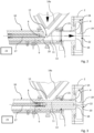
- the Figures 1 to 3 show at least parts of a mixing arrangement, designated as a whole by 1, for mixing solids in liquids.
- the mixing arrangement 1 comprises a mixing device 2 and a solids supply device 3 connected thereto. Solids, for example powder, can be supplied to the mixing device 2 via the solids supply device 3 .
- the mixing device 2 shown in the figures is a solid-liquid mixing device.
- the mixing device 2 is supplied with liquid into which the solid is to be mixed via a connection which is not shown.
- the mixing device 2 has a solids inlet 4 to which the solids supply device 3 is connected.
- the solids supply device 3 serves to supply the mixing device 2 with solids, in particular bulk material, for example powder.
- the solids feeding device 3 has a funnel 5 .
- the funnel 5 is used to hold solids.
- an emptying device 6 is arranged above the funnel 5 . Solids from big bags can be filled into the funnel 5 of the solids feed device 3 with the aid of this emptying device 6 .
- the solids supply device 3 also has a solids outlet 7, which can be connected to the previously mentioned solids inlet 4 of the mixing device 2 and according to the Figures 1 to 3 connected is.
- the solids outlet 7 of the solids supply device 3 is connected to the hopper 5 via a conveying connection 8 .
- the solids feed device 3 has a slide 9 which can be moved between a first end position (cf. figure 2 ) and a second end position (cf. figure 3 ) is movable through the conveyor connection 8.
- the distance between the two end positions is selected in such a way that the slide 9 can be moved through the entire conveying path of the conveying connection 8 .
- a protrusion that the slide 9 has in its second end position in relation to the solids outlet 7 is as large as a distance between an inlet cross section 21 into the solids inlet 4 and a discharge cross section 18 of the solids inlet 4 into a mixing chamber 19 of the mixing device connected to the solids feed device 3 2.
- the solids inlet 4 of the mixing device 2 is designed as a pipe socket.
- the slider 9 of the solids feed device 3 is a piston of a piston valve 10.
- the piston valve 10 is located downstream of the funnel 5 of the solids feed device 3 in the conveying direction of the solids through the solids feed device 3.
- the piston valve 10 has a housing 11 .
- the housing 11 not only forms the entire conveying connection 8 between the hopper 5 and the solids outlet 7 of the solids feed device 3 , but also has the solids outlet 7 .
- the funnel 5 includes a funnel outlet 12 which opens directly into the housing 11 of the piston valve 10 .
- a junction 13 of the funnel outlet 12 in the housing 11 of the piston valve 10 is arranged between the first end position and the second end position of the slide 9 .
- the funnel outlet 12 is arranged inside the conveyor connection 8, i.e. inside the housing 11.
- the opening 13 of the funnel outlet 12 is at least partially enclosed by the housing 11.
- the slide 9 can be moved through the opening 13 of the funnel outlet 12 .
- the housing 11 is connected directly to the funnel 5 as a result.
- the solids supply device 3 also includes a solids aerator 14 which ensures within the hopper 5 that the solids therein are loosened sufficiently and therefore remains fluid.
- the solids loosening device 14 has a drive 15 .
- About the drive 15 can in the Figures 2 and 3 wings 14a shown in section of the solids agitator 14 are rotated within the hopper 5 in order to aerate solids therein or keep them loose.
- An axis of rotation R of the solids aerator 14 is in figure 1 implied.
- the solids feed device 3 has a slide drive 16 .
- the slide drive 16 can be designed, for example, as a pneumatic or as an electric slide drive.
- Pneumatic or electric slide valve drives are particularly suitable for applications in the food and/or pharmaceutical sector due to the hygienic requirements there. In principle, the use of hydraulic slide drives would also be conceivable.
- the slide drive 16 is connected to the slide 9 via a spindle 17 .
- the slide 9 can be moved back and forth between the first end position and the second end position with the aid of the spindle 17 .
- the slide drive 16 can also have a gear, not shown in the figures, which can preferably be designed as a reduction gear. The slide drive 16 is then connected to the spindle 17 via the gear.
- FIG. 2 and 3 illustrate that the solids outlet 7 of the solids supply device 3 is connected to the solids inlet 4 of the mixing device 2 .
- the solids inlet 4 has an opening cross section 18 directly into a mixing chamber 19 of the mixing device 2 . Solids supplied via the solids inlet 4 can be introduced directly into the mixing chamber 19 of the mixing device 2 via this opening cross section 18 .
- An end face 20 of the slide 9 closes the opening cross section 18 of the solids inlet 4 flush with the wall when the slide 9 moves according to its second end position figure 3 has reached. In this way, it is ensured that the entire conveying distance, which is provided by the conveying connection 8, the solids outlet 7 and the solids inlet 4, can be covered by the slide 9 and, if necessary, freed from adhesions.
- figure 3 clarifies that a protrusion that the slide 9 has in its second end position relative to the solids outlet 7 is as large as a distance between an entry cross section 21 into the solids inlet 4 and the opening cross section 18 of the solids inlet 4 into the mixing chamber 19.
- the solids supply device 3 has a monitoring device 23 .
- the monitoring device 23 is set up to detect a blockage in the conveying connection 8 .
- the monitoring device 23 can be connected to a monitoring sensor 24 in the form of a pressure sensor.
- the monitoring sensor 24 can be arranged in the mixing chamber 19 of the mixing device 2 or also in the conveying connection 8 .
- the rotor-stator unit 22 of the mixing device 2 is set up to generate a negative pressure in the mixing chamber 19 .
- the solid is conveyed through the conveying connection 8 of the solid supply device 3 into the mixing chamber 19 of the mixing device 2 by the negative pressure. Once the conveyor connection 8 is clogged by buildup of solids, the Monitoring sensor 24 detect a drop in pressure in the mixing chamber 19 or in the delivery connection 8 .
- the monitoring device 23 can also monitor a power consumption of a drive of the rotor-stator unit 22 . If a drop in the power consumption of the drive can be detected, this can indicate a blockage in the conveying connection 8 and the slide 9 can be activated.
- the mixing arrangement 1 and the solids feed device 3 are set up to carry out the method described below:
- solids for example bulk material in the form of a powder
- the solids enter the mixing device 2 via the conveying connection 8 of the solids supply device 3 and here in particular into the mixing chamber 19 of the mixing device 2 .
- the solids supply device 3 has the slide 9 , as already explained above. This can be moved between its first end position and its second end position by the conveyor connection 8 and is set up to loosen the buildup of solid matter within the conveyor connection 8 .
- the slide 9 is activated and moved through the conveyor connection 8 to clear the conveyor connection 8 as soon as the conveyor connection 8 between the solids outlet 7 and the hopper 5 is blocked.
- the slide drive 16 is controlled and activated accordingly.
- the solid is conveyed, namely sucked in, into the mixing chamber 19 of the mixing device 2 with the aid of negative pressure.
- the Negative pressure, with which the solid is sucked in, is generated with the aid of the rotor-stator unit 22 of the mixing device 2 .
- the conveyor connection 8 is monitored for blockages with the monitoring device 23 of the solids feed device 3 .
- the monitoring device 23 activates the slide 9 at least indirectly as soon as a blockage of the conveying connection 8 is detected. In this way, the method can be carried out automatically.
- the blockage of the conveyor connection 8 can be detected, for example, based on a drop in power consumption of a drive of the rotor-stator unit 22 . It is also possible to detect the blockage of the delivery connection 8 based on a pressure change in the delivery connection 8 and/or in the mixing chamber 19 of the mixing device 2 .
- One or more monitoring sensors 24 of the monitoring device 23 embodied, for example, as pressure sensors can be used for this purpose.
- the invention addresses improvements in the art of feeding solids to mixing devices.
- the solids feed device 3 is proposed for this purpose.
- This has the slide 9 which can be moved between a first end position and a second end position by a conveyor connection 8 which is arranged between a hopper 5 and a solids outlet 7 of the solids feed device 3 .
- a conveyor connection 8 which is arranged between a hopper 5 and a solids outlet 7 of the solids feed device 3 .
Claims (15)
- Procédé d'alimentation de matières solides, en particulier de solides en vrac, tels que de la poudre, à un dispositif de mélange (2) en utilisant un dispositif d'alimentation de matières solides (3), dans lequel le dispositif d'alimentation de matières solides (3) comprend une trémie (5) pour recevoir des matières solides et une sortie de matières solides (7), qui est reliée à une entrée de matières solides (4) du dispositif de mélange (2), la sortie de matières solides (7) et la trémie (5) étant reliées l'une à l'autre par l'intermédiaire d'une liaison de transport (8), les matières solides étant amenées au dispositif de mélange (2) par l'intermédiaire de la liaison de transport (8), le dispositif d'alimentation de matières solides (3) comportant un poussoir (9) mobile entre une première position d'extrémité et une deuxième position d'extrémité à travers la liaison de transport (8), et où le poussoir (9) est agencé pour libérer des adhérences de matière solide à l'intérieur de la liaison de transport (8), caractérisé en ce que le poussoir (9) est activé et déplacé à travers la liaison de transport (8) afin de dégager la liaison de transport (8), dès que la liaison de transport (8) est obstruée entre la sortie de matières solides (7) et la trémie (5), une obstruction de la liaison de transport (8) étant détectée avec un dispositif de surveillance (23), lequel dispositif de surveillance (23) activant au moins indirectement le poussoir (9) dès qu'une obstruction de la liaison de transport (8) est détectée.
- Procédé selon la revendication 1, dans lequel la matière solide est transportée, en particulier aspirée, à l'aide d'une dépression dans le dispositif de mélange (2), en particulier dans une chambre de mélange (19) du dispositif de mélange (2), et dans lequel la dépression est de préférence générée à l'aide d'un ensemble rotor-stator (22) du dispositif de mélange (2).
- Procédé selon la revendication 2, dans lequel une obstruction de la liaison de transport (8) est détectée à l'aide d'une chute de la puissance absorbée de l'entraînement de l'unité rotor-stator 22) et/ou, en particulier, à l'aide d'un capteur de surveillance (24), par exemple un capteur de pression, détectant une variation de pression dans la liaison de transport (8) et/ou dans le dispositif de mélange (2), en particulier dans la chambre de mélange (19) du dispositif de mélange (2).
- Dispositif d'alimentation de matières solides, en particulier de solides en vrac, tels que de la poudre, à un dispositif de mélange (2) en utilisant un dispositif d'alimentation de matières solides (3), dans lequel le dispositif d'alimentation de matières solides (3) comprend une trémie (5) pour recevoir des matières solides et une sortie de matières solides (7), qui est reliée à une entrée de matières solides (4) du dispositif de mélange (2), la sortie de matières solides (7) et la trémie (5) étant reliées l'une à l'autre par l'intermédiaire d'une liaison de transport (8), les matières solides étant amenées au dispositif de mélange (2) par l'intermédiaire de la liaison de transport (8), le dispositif d'alimentation de matières solides (3) comportant un poussoir (9) mobile entre une première position d'extrémité et une deuxième position d'extrémité à travers la liaison de transport (8),caractérisé en ce que le dispositif d'alimentation de matières solides (3) est agencé pour mettre en oeuvre le procédé selon l'une des revendications précédentes et qu'il comporte un dispositif de surveillance (23) agencé pour détecter une obstruction de la liaison de transport (8) et pour activer au moins indirectement le poussoir (9).
- Dispositif d'alimentation de matières solides (3) selon la revendication précédente, caractérisé en ce que le poussoir (9) remplit la section libre de la liaison de transport (8) et/ou de la sortie de matières solides (7), et/ou en ce que le poussoir (9), dans sa deuxième position extrême, fait saillie hors de la sortie de matières solides (7) et/ou présente un débord par rapport à la sortie de matières solides (7), et dans lequel, en particulier, le dépassement que présente le poussoir (9) dans sa deuxième position extrême par rapport à la sortie de matières solides (7) est aussi grand que la distance entre une section transversale d'entrée (21) de l'alimentation de matières solides (4) et une section transversale d'embouchure (18) de l'alimentation de matières solides (4) dans la chambre de mélange (19) du dispositif de mélange (2) pouvant être relié au dispositif d'alimentation en matières solides (3).
- Dispositif d'alimentation de matières solides (3) selon l'une des revendications 4 ou 5, caractérisé en ce que le poussoir (9) est un piston d'une valve à piston (10) située en aval de la trémie (5) dans le sens de transport des matières solides à travers le dispositif d'alimentation de matières solides (3).
- Dispositif d'alimentation de matières solides (3) selon l'une des revendications 4 ou 5, caractérisé en ce que la trémie (5) comporte une sortie de trémie (12) débouchant dans la liaison de transport (8), notamment dans le boîtier (11) de la valve à piston (10), dans lequel boîtier (11) une embouchure (13) de la sortie de trémie (12) est agencée de préférence entre la première position d'extrémité et la deuxième position d'extrémité du poussoir (9).
- Dispositif d'alimentation de matières solides (3) selon l'une des revendications 4 à 7, caractérisé en ce que la sortie de trémie (12) est agencée au sein de la liaison de transport (8) et que le poussoir (9) est mobile à travers l'embouchure (13) de la sortie de trémie (12), et/ou en ce que le dispositif d'alimentation de matières solides (3) comporte, notamment dans ou sur la trémie, un ameublisseur de matières solides (14) et/ou un fluidificateur et/ou un vibrateur et/ou un cogneur.
- Dispositif d'alimentation de matières solides (3) selon l'une des revendications 4 à 8, caractérisé en ce que le dispositif d'alimentation de matières solides (3) comporte notamment un capteur de surveillance (24), par exemple un capteur de pression, et/ou qu'il est relié à un capteur de surveillance (24), par exemple un capteur de pression.
- Ensemble de mélange (1) comprenant au moins un dispositif de mélange (2) et au moins un dispositif d'alimentation de matières solides (3) selon l'une quelconque des revendications 4 à 9.
- Ensemble de mélange (1) selon la revendication précédente, dans lequel le dispositif de mélange (2) est un dispositif de mélange solide-liquide, comportant notamment une unité rotor-stator (22) disposée dans une chambre de mélange (19) du dispositif de mélange (2), en particulier dans lequel l'unité rotor-stator (22) est agencée pour générer une dépression dans la chambre de mélange (19), à l'aide de laquelle la matière solide peut être transportée par la liaison de transport (8) du dispositif d'alimentation en matières solides (3) dans le dispositif de mélange (3), en particulier dans une chambre de mélange (19) du dispositif de mélange (3).
- Ensemble de mélange (1) selon l'une des revendications 10 ou 11, dans lequel au moins un dispositif de mélange (2) comprend une entrée de matières solides (4) reliée à la sortie de matières solides (7) dudit dispositif d'alimentation de matières solides (3), dans lequel l'entrée de matières solides (4) débouche par une section d'embouchure (18) dans une chambre de mélange (19) du dispositif de mélange (2), et dans lequel le poussoir (9) du dispositif d'alimentation en matières solides (3), dans sa deuxième position d'extrémité, remplit la section d'embouchure (18) et/ou fait saillie de la section d'embouchure dans la chambre de mélange (19).
- Ensemble de mélange (1) selon l'une quelconque des revendications 10 à 12, dans lequel un débord que présente le poussoir (9) dans sa deuxième position extrême par rapport à la sortie de matières solides (7) du dispositif d'alimentation de matières solides (3) est aussi grand que la distance entre une section transversale d'entrée (21) du dispositif d'alimentation de matières solides (4) et une ou la section transversale d'embouchure (18) de l'entrée de matières solides (4) dans une ou la chambre de mélange (19).
- Ensemble de mélange (1) selon l'une des revendications 10 à 13, caractérisé en ce que l'ensemble de mélange (1) est agencé pour mettre en oeuvre le procédé selon l'une des revendications précédentes.
- Utilisation d'un dispositif d'alimentation de matières solides (3) selon l'une des revendications 4 à 9 et/ou d'un ensemble de mélange (1) selon l'une des revendications 10 à 14 dans la mise en oeuvre du procédé selon l'une des revendications précédentes.
Applications Claiming Priority (3)
| Application Number | Priority Date | Filing Date | Title |
|---|---|---|---|
| DE102019100619 | 2019-01-11 | ||
| DE102019102183.9A DE102019102183A1 (de) | 2019-01-11 | 2019-01-29 | Feststoffzuführvorrichtung und Mischanordnung |
| PCT/EP2020/050423 WO2020144276A1 (fr) | 2019-01-11 | 2020-01-09 | Procédé d'alimentation en matières solides d'un dispositif de mélange, dispositif d'alimentation en matières solides et dispositif de mélange |
Publications (3)
| Publication Number | Publication Date |
|---|---|
| EP3908543A1 EP3908543A1 (fr) | 2021-11-17 |
| EP3908543B1 true EP3908543B1 (fr) | 2023-06-07 |
| EP3908543C0 EP3908543C0 (fr) | 2023-06-07 |
Family
ID=71131939
Family Applications (1)
| Application Number | Title | Priority Date | Filing Date |
|---|---|---|---|
| EP20700777.4A Active EP3908543B1 (fr) | 2019-01-11 | 2020-01-09 | Procédé d'alimentation en matières solides d'un dispositif de mélange, dispositif d'alimentation en matières solides et dispositif de mélange |
Country Status (9)
| Country | Link |
|---|---|
| US (1) | US20220088553A1 (fr) |
| EP (1) | EP3908543B1 (fr) |
| JP (1) | JP2022517567A (fr) |
| BR (1) | BR112021012802A2 (fr) |
| DE (1) | DE102019102183A1 (fr) |
| ES (1) | ES2954598T3 (fr) |
| PL (1) | PL3908543T3 (fr) |
| RU (1) | RU2765394C1 (fr) |
| WO (1) | WO2020144276A1 (fr) |
Families Citing this family (5)
| Publication number | Priority date | Publication date | Assignee | Title |
|---|---|---|---|---|
| CN113813858B (zh) * | 2021-11-10 | 2023-01-31 | 西安国际医学中心有限公司 | 一种治疗癌症疼痛膏药制作的混料装置 |
| CN114870734A (zh) * | 2022-06-01 | 2022-08-09 | 西安新三力复合材料科技有限公司 | 一种石墨烯生产用自动搅拌装置 |
| CN115318189B (zh) * | 2022-08-30 | 2023-11-17 | 郑州三华科技实业有限公司 | 涂料调色系统和涂料的调色方法 |
| CN115870303B (zh) * | 2022-10-28 | 2023-07-04 | 安吉纳海环境有限公司 | 一种固废前处理系统及固废处理工艺 |
| CN115591499B (zh) * | 2022-11-04 | 2023-06-16 | 中山华明泰科技股份有限公司 | 一种外墙用防水丙烯酸乳液的制备方法、装置 |
Family Cites Families (9)
| Publication number | Priority date | Publication date | Assignee | Title |
|---|---|---|---|---|
| US1974789A (en) * | 1930-09-20 | 1934-09-25 | Universal Oil Preducts Company | Means of charging solid material into a confined zone |
| US2906417A (en) * | 1951-09-22 | 1959-09-29 | Rossi Giovanni | Material conveying device |
| CH681002A5 (fr) * | 1989-12-22 | 1992-12-31 | List Ag | |
| DE19528636A1 (de) * | 1995-08-04 | 1997-02-06 | Motan Holding Gmbh | Einrichtung zum Fördern und Dosieren von Schüttgut |
| DE50007630D1 (de) * | 2000-10-11 | 2004-10-07 | Vakumix Ruehr Und Homogenisier | Vorrichtung zum Homogenisieren fliessfähiger Stoffe |
| JP2005200202A (ja) * | 2004-01-19 | 2005-07-28 | Jfe Engineering Kk | 含水物の圧送装置 |
| DE102007006755A1 (de) * | 2007-02-12 | 2008-08-14 | Feldhaus Technik Gmbh | Pneumatische Dosierfördervorrichung für Pulver, Stäube und Granulate im Nieder- und Hochdruckbereich |
| JP5575069B2 (ja) * | 2011-08-08 | 2014-08-20 | 東芝機械株式会社 | ペレット供給装置 |
| DE102015110865A1 (de) * | 2015-07-06 | 2017-01-12 | Thyssenkrupp Ag | Trennvorrichtung und Verfahren zum Detektieren einer Stoffansammlung in einer solchen Trennvorrichtung |
-
2019
- 2019-01-29 DE DE102019102183.9A patent/DE102019102183A1/de not_active Withdrawn
-
2020
- 2020-01-09 EP EP20700777.4A patent/EP3908543B1/fr active Active
- 2020-01-09 JP JP2021538980A patent/JP2022517567A/ja active Pending
- 2020-01-09 US US17/421,642 patent/US20220088553A1/en active Pending
- 2020-01-09 WO PCT/EP2020/050423 patent/WO2020144276A1/fr unknown
- 2020-01-09 ES ES20700777T patent/ES2954598T3/es active Active
- 2020-01-09 BR BR112021012802-6A patent/BR112021012802A2/pt unknown
- 2020-01-09 PL PL20700777.4T patent/PL3908543T3/pl unknown
- 2020-01-09 RU RU2021122351A patent/RU2765394C1/ru active
Also Published As
| Publication number | Publication date |
|---|---|
| PL3908543T3 (pl) | 2023-11-06 |
| BR112021012802A2 (pt) | 2021-09-14 |
| JP2022517567A (ja) | 2022-03-09 |
| EP3908543A1 (fr) | 2021-11-17 |
| WO2020144276A1 (fr) | 2020-07-16 |
| DE102019102183A1 (de) | 2020-07-16 |
| RU2765394C1 (ru) | 2022-01-28 |
| US20220088553A1 (en) | 2022-03-24 |
| ES2954598T3 (es) | 2023-11-23 |
| EP3908543C0 (fr) | 2023-06-07 |
Similar Documents
| Publication | Publication Date | Title |
|---|---|---|
| EP3908543B1 (fr) | Procédé d'alimentation en matières solides d'un dispositif de mélange, dispositif d'alimentation en matières solides et dispositif de mélange | |
| EP2564946B1 (fr) | Procédé de nettoyage de dispositifs de dosage servant au remplissage de dispositifs (par exemple installation d'extrusion, machines de moulage par injection ou analogues) avec des produits en vrac (pellets, copeaux, granulés, poudres, flocons, grains, farine ou analogues) et dispositif de réalisation d'un procédé de ce type et commande pour le nettoyage d'un dispositif de dosage de ce type | |
| EP1931953B1 (fr) | Dispositif de dosage pour substances pulverulentes ou pateuses | |
| EP1593295B1 (fr) | Système de distribution pour un produit agricole | |
| DE102007005250B3 (de) | Verfahren zum kontinuierlichen Trockenmahlbetrieb einer Turmreibmühle und Turmreibmühle | |
| EP2072974A1 (fr) | Appareil de laboratoire doté d'un dispositif de guidage de produit de dosage | |
| DE112008000816B4 (de) | Vorrichtung zum Fördern von Strahlmedium, insbesondere von Eis, Eispellets, Eisschnee oder wasserlöslichem Strahlmittel | |
| EP2342060A1 (fr) | Dispositif de dosage | |
| EP3423203B1 (fr) | Dispositif et procédé pour l'introduction simultanée de particules de matériau synthétique et d'un liquide dans un dispositif de nettoyage | |
| CH660073A5 (de) | Vakuum-trocken-vorrichtung. | |
| EP1152228B1 (fr) | Dispositif de dosage pour le remplissage des recipients avec petite ouverture | |
| DE102009023546B4 (de) | Dosiervorrichtung zum Einbringen eines pulverförmigen Mediums in eine Flüssigkeit | |
| EP3523201B1 (fr) | Dispositif de remplissage pour une empaqueteuse de produits en vrac dans des récipients | |
| DE10252527A1 (de) | Vorrichtung zur Einbringung von trockenen organischen Stoffen in einen Vergärungsbehälter einer Biogasanlage | |
| DE102010016634B4 (de) | Dosierautomat zum dosierten Streuen von Gewürzen | |
| EP2482643B1 (fr) | Véhicule pour la préparation mobile de fourrage mêlangé | |
| EP1666133B1 (fr) | Dispositif de mélange monté sur camion | |
| DE102006014090B3 (de) | Mobile Mischanlage zur Zumischung von Tierarzneimitteln in landwirtschaftliche Güter | |
| DE10142113A1 (de) | Sprühkasten | |
| CH507138A (de) | Einrichtung zum Fördern und Dosieren von pastösen, klebrigen und rieselfähigen Materialien | |
| DE3502765C2 (de) | Förderschnecke zum Dosieren | |
| DE202010005304U1 (de) | Dosierautomat zum dosierten Streuen von Gewürzen | |
| DE10033837C1 (de) | Druckluftfördergerät für Schüttgüter | |
| DE3322180C2 (de) | Vorrichtung zum Vermischen von körnigem oder stückigem Material mit einer Flüssigkeit | |
| DE4403607A1 (de) | Einrichtung zur dosierten Zuführung von mittels einer Schredderanlage erzeugten Schnipseln aus Papier oder Pappe zu einer Schlauchbeutelverpackungsmaschine |
Legal Events
| Date | Code | Title | Description |
|---|---|---|---|
| STAA | Information on the status of an ep patent application or granted ep patent |
Free format text: STATUS: UNKNOWN |
|
| STAA | Information on the status of an ep patent application or granted ep patent |
Free format text: STATUS: THE INTERNATIONAL PUBLICATION HAS BEEN MADE |
|
| PUAI | Public reference made under article 153(3) epc to a published international application that has entered the european phase |
Free format text: ORIGINAL CODE: 0009012 |
|
| STAA | Information on the status of an ep patent application or granted ep patent |
Free format text: STATUS: REQUEST FOR EXAMINATION WAS MADE |
|
| 17P | Request for examination filed |
Effective date: 20210811 |
|
| AK | Designated contracting states |
Kind code of ref document: A1 Designated state(s): AL AT BE BG CH CY CZ DE DK EE ES FI FR GB GR HR HU IE IS IT LI LT LU LV MC MK MT NL NO PL PT RO RS SE SI SK SM TR |
|
| DAV | Request for validation of the european patent (deleted) | ||
| DAX | Request for extension of the european patent (deleted) | ||
| REG | Reference to a national code |
Ref country code: DE Ref legal event code: R079 Ref document number: 502020003611 Country of ref document: DE Free format text: PREVIOUS MAIN CLASS: B65G0053460000 Ipc: B65G0053520000 |
|
| RIC1 | Information provided on ipc code assigned before grant |
Ipc: B01F 35/71 20220101ALI20220914BHEP Ipc: B01F 27/271 20220101ALI20220914BHEP Ipc: B01F 23/53 20220101ALI20220914BHEP Ipc: B65G 53/46 20060101ALI20220914BHEP Ipc: B65G 53/52 20060101AFI20220914BHEP |
|
| GRAP | Despatch of communication of intention to grant a patent |
Free format text: ORIGINAL CODE: EPIDOSNIGR1 |
|
| STAA | Information on the status of an ep patent application or granted ep patent |
Free format text: STATUS: GRANT OF PATENT IS INTENDED |
|
| RIN1 | Information on inventor provided before grant (corrected) |
Inventor name: OTTE, ANDREAS Inventor name: GRIMM, UWE |
|
| INTG | Intention to grant announced |
Effective date: 20221121 |
|
| GRAS | Grant fee paid |
Free format text: ORIGINAL CODE: EPIDOSNIGR3 |
|
| GRAA | (expected) grant |
Free format text: ORIGINAL CODE: 0009210 |
|
| STAA | Information on the status of an ep patent application or granted ep patent |
Free format text: STATUS: THE PATENT HAS BEEN GRANTED |
|
| AK | Designated contracting states |
Kind code of ref document: B1 Designated state(s): AL AT BE BG CH CY CZ DE DK EE ES FI FR GB GR HR HU IE IS IT LI LT LU LV MC MK MT NL NO PL PT RO RS SE SI SK SM TR |
|
| REG | Reference to a national code |
Ref country code: GB Ref legal event code: FG4D Free format text: NOT ENGLISH |
|
| REG | Reference to a national code |
Ref country code: CH Ref legal event code: EP Ref country code: AT Ref legal event code: REF Ref document number: 1574460 Country of ref document: AT Kind code of ref document: T Effective date: 20230615 |
|
| REG | Reference to a national code |
Ref country code: DE Ref legal event code: R096 Ref document number: 502020003611 Country of ref document: DE |
|
| U01 | Request for unitary effect filed |
Effective date: 20230607 |
|
| U07 | Unitary effect registered |
Designated state(s): AT BE BG DE DK EE FI FR IT LT LU LV MT NL PT SE SI Effective date: 20230612 |
|
| REG | Reference to a national code |
Ref country code: LT Ref legal event code: MG9D |
|
| PG25 | Lapsed in a contracting state [announced via postgrant information from national office to epo] |
Ref country code: NO Free format text: LAPSE BECAUSE OF FAILURE TO SUBMIT A TRANSLATION OF THE DESCRIPTION OR TO PAY THE FEE WITHIN THE PRESCRIBED TIME-LIMIT Effective date: 20230907 |
|
| PG25 | Lapsed in a contracting state [announced via postgrant information from national office to epo] |
Ref country code: RS Free format text: LAPSE BECAUSE OF FAILURE TO SUBMIT A TRANSLATION OF THE DESCRIPTION OR TO PAY THE FEE WITHIN THE PRESCRIBED TIME-LIMIT Effective date: 20230607 Ref country code: HR Free format text: LAPSE BECAUSE OF FAILURE TO SUBMIT A TRANSLATION OF THE DESCRIPTION OR TO PAY THE FEE WITHIN THE PRESCRIBED TIME-LIMIT Effective date: 20230607 Ref country code: GR Free format text: LAPSE BECAUSE OF FAILURE TO SUBMIT A TRANSLATION OF THE DESCRIPTION OR TO PAY THE FEE WITHIN THE PRESCRIBED TIME-LIMIT Effective date: 20230908 |
|
| PG25 | Lapsed in a contracting state [announced via postgrant information from national office to epo] |
Ref country code: SK Free format text: LAPSE BECAUSE OF FAILURE TO SUBMIT A TRANSLATION OF THE DESCRIPTION OR TO PAY THE FEE WITHIN THE PRESCRIBED TIME-LIMIT Effective date: 20230607 |
|
| PG25 | Lapsed in a contracting state [announced via postgrant information from national office to epo] |
Ref country code: IS Free format text: LAPSE BECAUSE OF FAILURE TO SUBMIT A TRANSLATION OF THE DESCRIPTION OR TO PAY THE FEE WITHIN THE PRESCRIBED TIME-LIMIT Effective date: 20231007 |
|
| PG25 | Lapsed in a contracting state [announced via postgrant information from national office to epo] |
Ref country code: SM Free format text: LAPSE BECAUSE OF FAILURE TO SUBMIT A TRANSLATION OF THE DESCRIPTION OR TO PAY THE FEE WITHIN THE PRESCRIBED TIME-LIMIT Effective date: 20230607 Ref country code: SK Free format text: LAPSE BECAUSE OF FAILURE TO SUBMIT A TRANSLATION OF THE DESCRIPTION OR TO PAY THE FEE WITHIN THE PRESCRIBED TIME-LIMIT Effective date: 20230607 Ref country code: RO Free format text: LAPSE BECAUSE OF FAILURE TO SUBMIT A TRANSLATION OF THE DESCRIPTION OR TO PAY THE FEE WITHIN THE PRESCRIBED TIME-LIMIT Effective date: 20230607 Ref country code: IS Free format text: LAPSE BECAUSE OF FAILURE TO SUBMIT A TRANSLATION OF THE DESCRIPTION OR TO PAY THE FEE WITHIN THE PRESCRIBED TIME-LIMIT Effective date: 20231007 |
|
| U20 | Renewal fee paid [unitary effect] |
Year of fee payment: 5 Effective date: 20240115 |
|
| PGFP | Annual fee paid to national office [announced via postgrant information from national office to epo] |
Ref country code: PL Payment date: 20231228 Year of fee payment: 5 |
|
| REG | Reference to a national code |
Ref country code: DE Ref legal event code: R097 Ref document number: 502020003611 Country of ref document: DE |
|
| PLBE | No opposition filed within time limit |
Free format text: ORIGINAL CODE: 0009261 |
|
| STAA | Information on the status of an ep patent application or granted ep patent |
Free format text: STATUS: NO OPPOSITION FILED WITHIN TIME LIMIT |
|
| PGFP | Annual fee paid to national office [announced via postgrant information from national office to epo] |
Ref country code: IE Payment date: 20240118 Year of fee payment: 5 Ref country code: ES Payment date: 20240216 Year of fee payment: 5 |