EP3908543B1 - Method for feeding solid material to a mixing device, solid-material feeding device and mixing assembly - Google Patents
Method for feeding solid material to a mixing device, solid-material feeding device and mixing assembly Download PDFInfo
- Publication number
- EP3908543B1 EP3908543B1 EP20700777.4A EP20700777A EP3908543B1 EP 3908543 B1 EP3908543 B1 EP 3908543B1 EP 20700777 A EP20700777 A EP 20700777A EP 3908543 B1 EP3908543 B1 EP 3908543B1
- Authority
- EP
- European Patent Office
- Prior art keywords
- solid material
- mixing
- solids
- slide
- outlet
- Prior art date
- Legal status (The legal status is an assumption and is not a legal conclusion. Google has not performed a legal analysis and makes no representation as to the accuracy of the status listed.)
- Active
Links
- 238000000034 method Methods 0.000 title claims description 24
- 239000011343 solid material Substances 0.000 title claims 53
- 239000007787 solid Substances 0.000 claims description 234
- 239000000843 powder Substances 0.000 claims description 19
- 238000012544 monitoring process Methods 0.000 claims description 17
- 239000007788 liquid Substances 0.000 claims description 9
- 239000013590 bulk material Substances 0.000 claims description 6
- 230000008859 change Effects 0.000 claims description 4
- -1 for example Substances 0.000 claims 2
- 230000003213 activating effect Effects 0.000 claims 1
- 230000004913 activation Effects 0.000 claims 1
- 238000001514 detection method Methods 0.000 claims 1
- 238000012806 monitoring device Methods 0.000 description 17
- 238000005276 aerator Methods 0.000 description 3
- 239000000463 material Substances 0.000 description 3
- 230000009467 reduction Effects 0.000 description 3
- GWEVSGVZZGPLCZ-UHFFFAOYSA-N Titan oxide Chemical compound O=[Ti]=O GWEVSGVZZGPLCZ-UHFFFAOYSA-N 0.000 description 2
- 230000008901 benefit Effects 0.000 description 2
- 239000000203 mixture Substances 0.000 description 2
- 238000009825 accumulation Methods 0.000 description 1
- 239000011248 coating agent Substances 0.000 description 1
- 238000000576 coating method Methods 0.000 description 1
- 239000012530 fluid Substances 0.000 description 1
- 239000008187 granular material Substances 0.000 description 1
- 230000008569 process Effects 0.000 description 1
- 230000035939 shock Effects 0.000 description 1
- 238000003756 stirring Methods 0.000 description 1
- 239000004408 titanium dioxide Substances 0.000 description 1
- 238000011144 upstream manufacturing Methods 0.000 description 1
Images

Classifications
-
- B—PERFORMING OPERATIONS; TRANSPORTING
- B01—PHYSICAL OR CHEMICAL PROCESSES OR APPARATUS IN GENERAL
- B01F—MIXING, e.g. DISSOLVING, EMULSIFYING OR DISPERSING
- B01F35/00—Accessories for mixers; Auxiliary operations or auxiliary devices; Parts or details of general application
- B01F35/10—Maintenance of mixers
- B01F35/12—Maintenance of mixers using mechanical means
- B01F35/122—Maintenance of mixers using mechanical means using pushers, i.e. a piston, for pushing out rests of products
-
- B—PERFORMING OPERATIONS; TRANSPORTING
- B01—PHYSICAL OR CHEMICAL PROCESSES OR APPARATUS IN GENERAL
- B01F—MIXING, e.g. DISSOLVING, EMULSIFYING OR DISPERSING
- B01F23/00—Mixing according to the phases to be mixed, e.g. dispersing or emulsifying
- B01F23/50—Mixing liquids with solids
- B01F23/53—Mixing liquids with solids using driven stirrers
-
- B—PERFORMING OPERATIONS; TRANSPORTING
- B01—PHYSICAL OR CHEMICAL PROCESSES OR APPARATUS IN GENERAL
- B01F—MIXING, e.g. DISSOLVING, EMULSIFYING OR DISPERSING
- B01F23/00—Mixing according to the phases to be mixed, e.g. dispersing or emulsifying
- B01F23/50—Mixing liquids with solids
- B01F23/59—Mixing systems, i.e. flow charts or diagrams
-
- B—PERFORMING OPERATIONS; TRANSPORTING
- B01—PHYSICAL OR CHEMICAL PROCESSES OR APPARATUS IN GENERAL
- B01F—MIXING, e.g. DISSOLVING, EMULSIFYING OR DISPERSING
- B01F27/00—Mixers with rotary stirring devices in fixed receptacles; Kneaders
- B01F27/27—Mixers with stator-rotor systems, e.g. with intermeshing teeth or cylinders or having orifices
- B01F27/271—Mixers with stator-rotor systems, e.g. with intermeshing teeth or cylinders or having orifices with means for moving the materials to be mixed radially between the surfaces of the rotor and the stator
-
- B—PERFORMING OPERATIONS; TRANSPORTING
- B01—PHYSICAL OR CHEMICAL PROCESSES OR APPARATUS IN GENERAL
- B01F—MIXING, e.g. DISSOLVING, EMULSIFYING OR DISPERSING
- B01F35/00—Accessories for mixers; Auxiliary operations or auxiliary devices; Parts or details of general application
- B01F35/20—Measuring; Control or regulation
- B01F35/21—Measuring
- B01F35/211—Measuring of the operational parameters
- B01F35/2113—Pressure
-
- B—PERFORMING OPERATIONS; TRANSPORTING
- B01—PHYSICAL OR CHEMICAL PROCESSES OR APPARATUS IN GENERAL
- B01F—MIXING, e.g. DISSOLVING, EMULSIFYING OR DISPERSING
- B01F35/00—Accessories for mixers; Auxiliary operations or auxiliary devices; Parts or details of general application
- B01F35/20—Measuring; Control or regulation
- B01F35/21—Measuring
- B01F35/212—Measuring of the driving system data, e.g. torque, speed or power data
-
- B—PERFORMING OPERATIONS; TRANSPORTING
- B01—PHYSICAL OR CHEMICAL PROCESSES OR APPARATUS IN GENERAL
- B01F—MIXING, e.g. DISSOLVING, EMULSIFYING OR DISPERSING
- B01F35/00—Accessories for mixers; Auxiliary operations or auxiliary devices; Parts or details of general application
- B01F35/71—Feed mechanisms
- B01F35/717—Feed mechanisms characterised by the means for feeding the components to the mixer
- B01F35/7173—Feed mechanisms characterised by the means for feeding the components to the mixer using gravity, e.g. from a hopper
- B01F35/71731—Feed mechanisms characterised by the means for feeding the components to the mixer using gravity, e.g. from a hopper using a hopper
-
- B—PERFORMING OPERATIONS; TRANSPORTING
- B01—PHYSICAL OR CHEMICAL PROCESSES OR APPARATUS IN GENERAL
- B01F—MIXING, e.g. DISSOLVING, EMULSIFYING OR DISPERSING
- B01F35/00—Accessories for mixers; Auxiliary operations or auxiliary devices; Parts or details of general application
- B01F35/71—Feed mechanisms
- B01F35/717—Feed mechanisms characterised by the means for feeding the components to the mixer
- B01F35/718—Feed mechanisms characterised by the means for feeding the components to the mixer using vacuum, under pressure in a closed receptacle or circuit system
-
- B—PERFORMING OPERATIONS; TRANSPORTING
- B65—CONVEYING; PACKING; STORING; HANDLING THIN OR FILAMENTARY MATERIAL
- B65G—TRANSPORT OR STORAGE DEVICES, e.g. CONVEYORS FOR LOADING OR TIPPING, SHOP CONVEYOR SYSTEMS OR PNEUMATIC TUBE CONVEYORS
- B65G43/00—Control devices, e.g. for safety, warning or fault-correcting
-
- B—PERFORMING OPERATIONS; TRANSPORTING
- B65—CONVEYING; PACKING; STORING; HANDLING THIN OR FILAMENTARY MATERIAL
- B65G—TRANSPORT OR STORAGE DEVICES, e.g. CONVEYORS FOR LOADING OR TIPPING, SHOP CONVEYOR SYSTEMS OR PNEUMATIC TUBE CONVEYORS
- B65G47/00—Article or material-handling devices associated with conveyors; Methods employing such devices
- B65G47/02—Devices for feeding articles or materials to conveyors
- B65G47/16—Devices for feeding articles or materials to conveyors for feeding materials in bulk
- B65G47/18—Arrangements or applications of hoppers or chutes
- B65G47/19—Arrangements or applications of hoppers or chutes having means for controlling material flow, e.g. to prevent overloading
-
- B—PERFORMING OPERATIONS; TRANSPORTING
- B65—CONVEYING; PACKING; STORING; HANDLING THIN OR FILAMENTARY MATERIAL
- B65G—TRANSPORT OR STORAGE DEVICES, e.g. CONVEYORS FOR LOADING OR TIPPING, SHOP CONVEYOR SYSTEMS OR PNEUMATIC TUBE CONVEYORS
- B65G53/00—Conveying materials in bulk through troughs, pipes or tubes by floating the materials or by flow of gas, liquid or foam
- B65G53/34—Details
- B65G53/40—Feeding or discharging devices
- B65G53/46—Gates or sluices, e.g. rotary wheels
- B65G53/4683—Gates or sluices, e.g. rotary wheels with a reciprocating mover acting directly on material
-
- B—PERFORMING OPERATIONS; TRANSPORTING
- B65—CONVEYING; PACKING; STORING; HANDLING THIN OR FILAMENTARY MATERIAL
- B65G—TRANSPORT OR STORAGE DEVICES, e.g. CONVEYORS FOR LOADING OR TIPPING, SHOP CONVEYOR SYSTEMS OR PNEUMATIC TUBE CONVEYORS
- B65G53/00—Conveying materials in bulk through troughs, pipes or tubes by floating the materials or by flow of gas, liquid or foam
- B65G53/34—Details
- B65G53/52—Adaptations of pipes or tubes
- B65G53/521—Adaptations of pipes or tubes means for preventing the accumulation or for removal of deposits
-
- B—PERFORMING OPERATIONS; TRANSPORTING
- B01—PHYSICAL OR CHEMICAL PROCESSES OR APPARATUS IN GENERAL
- B01F—MIXING, e.g. DISSOLVING, EMULSIFYING OR DISPERSING
- B01F2101/00—Mixing characterised by the nature of the mixed materials or by the application field
- B01F2101/06—Mixing of food ingredients
-
- B—PERFORMING OPERATIONS; TRANSPORTING
- B01—PHYSICAL OR CHEMICAL PROCESSES OR APPARATUS IN GENERAL
- B01F—MIXING, e.g. DISSOLVING, EMULSIFYING OR DISPERSING
- B01F2101/00—Mixing characterised by the nature of the mixed materials or by the application field
- B01F2101/22—Mixing of ingredients for pharmaceutical or medical compositions
Definitions
- the invention relates to a method for feeding solids to a mixing device using a solids feeding device.
- the invention also relates to a solids feed device for feeding solids, in particular bulk material, such as powder, to a mixing device, the solids feed device having a hopper for receiving solids and a solids outlet which can be connected to a solids inlet of a mixing device, the solids outlet and the hopper are connected to each other via a conveyor connection.
- the invention also relates to a mixing arrangement with at least one mixing device and at least one solids supply device and the use of a solids supply device and/or a mixing arrangement in a method of the type mentioned at the outset.
- Solids supply devices are from practice and also from the printed state of the art, for example from the publications WO 2008/098706 A1 , EP 1 197 260 A1 , DE 10 2015 110 865 A1 , U.S. 1,974,789 A and JP 2013 035 030 A previously known in various embodiments. They are used to pick up solids, such as powder or granules, and feed them to a downstream mixing device.
- WO2008/098706A1 discloses the preamble of claims 1 and 4.
- mixing devices that are operated together with such solids feed devices in so-called mixing arrangements are often solid-liquid mixing devices that are used to introduce solids into a liquid and mix it with it as uniformly as possible mix.
- So-called suction lances, sack chutes or big-bag emptying stations are often used to feed the solids, i.e. to transfer the solids to the solids feed device.
- the solids are then fed to the downstream mixing devices with the aid of the solids feed devices.
- this feed is sometimes better or worse.
- the feed usually succeeds without any problems.
- the conveyor connection downstream of the hopper is generally not affected by the vibrations and shocks that are transmitted to the hopper by such knockers and vibrators.
- the supply of remains problematic Solids through the conveyor connection that is necessary between the hopper and the solids outlet of the solids feeder.
- the object of the invention is therefore to provide a method, a solids supply device and a mixing arrangement of the type mentioned at the outset which avoid the aforementioned problems and simplify the supply of solids.
- a method with the means and features of the independent claim directed to a method for feeding solids to a mixing device is first proposed.
- a method for feeding solids for example bulk material such as powder
- the solids feeding device comprises a hopper for receiving solids and a solids outlet which is connected to a solids inlet of the mixing device to which the solids are to be fed.
- the solids outlet and the hopper are connected to one another via a conveyor connection of the solids feed device.
- the solid is fed via the conveying connection to the mixing device, here in particular to a mixing chamber of the mixing device.
- the solids supply device has a slide which can be moved between a first end position and a second end position by the conveyor connection and is set up to buildup of solids within the to release the delivery connection. According to the invention, the slide is activated and moved through the conveyor connection to clear the conveyor connection as soon as the conveyor connection between the solids outlet and the hopper is blocked.
- Adhesion of solids that can become lodged within the conveyor connection of the solids feed device can thus be removed particularly easily and without dismantling the conveyor connection.
- One embodiment of the method provides for the solid to be conveyed, for example sucked, into the mixing device, here in particular into a mixing chamber of the mixing device, with the aid of negative pressure.
- the negative pressure with which the solids can be fed to the mixing device can be generated, for example, with a rotor-stator unit of the mixing device.
- the rotor-stator unit can be arranged in one, for example in the previously mentioned mixing chamber of the mixing device.
- the solid With the aid of the negative pressure, the solid can be sucked into the mixing chamber of the mixing device through the conveying connection of the solid supply device.
- a continuous pressure connection can be opened between the mixing chamber of the mixing device and the hopper of the solid supply device, which is not affected by the slide. Only in the event of a blockage in the conveyor connection is the slide activated and moved through the conveyor connection to clear the conveyor connection.
- blockages in the conveying connection are detected with a monitoring device.
- the monitoring device can be a monitoring device be solid feeder.
- the monitoring device activates the slide, in particular a slide drive of the solids feed device, at least indirectly as soon as a blockage of the conveyor connection is detected.
- the monitoring device can automatically activate the slide, in particular a slide drive, at least indirectly, causing the slide to be moved through the conveyor connection in order to loosen any blockages and free the conveyor connection from buildup.
- a blockage of the delivery connection can be detected based on a drop in power consumption of a drive of the rotor-stator unit of the mixing device.
- a monitoring sensor of the monitoring device it is also possible to use a monitoring sensor of the monitoring device to detect a blockage in the delivery connection.
- a blockage of the delivery connection is detected based on a pressure change in the mixing device, in particular based on a pressure change in the mixing chamber of the mixing device.
- a monitoring sensor in the form of a pressure sensor can be used for this purpose, for example, which is arranged in the mixing chamber or in the area of the mixing chamber or in the delivery connection. If the delivery connection is blocked, a pressure drop can be registered with the pressure sensor.
- a defined drop in pressure for example in the mixing chamber, can indicate a blockage in the delivery connection.
- a sensor signal generated by a corresponding monitoring sensor can be used by the monitoring device to at least indirectly activate the slide, in particular a slide drive, in order to move the slide through the conveyor connection. So can the conveyor connection cleared automatically in the event of blockages and the process can be carried out automatically.
- a solids feed device is also proposed with the features of the independent claim directed to such a solids feed device.
- the object is thus achieved in particular in that the solids feed device has a slide which can be moved between a first end position and a second end position by the conveyor connection.
- the slide can be activated and used by moving it between the two end positions to clear the conveyor connection.
- a slide drive of the solids feed device can be activated.
- the slide In the first end position, the slide can release the conveyor connection, while in the second end position it can close the conveyor connection. If the slide closes the conveying connection, a supply of solids within the solids supply device is spatially separated from downstream areas, in particular from a mixing chamber of a mixing device connected to the solids supply device. The slide can thus be used to prevent the solid from coming into contact with a liquid that is present or circulating in the mixing device.
- the funnel can also be referred to quite generally and in accordance with its function as a solids receiving element of the solids feed device. It is used to pick up solids from an upstream section, for example from a chute and/or from a storage bag, and to feed them to the downstream conveyor sections of the conveyor feed device.
- the slide fills an open cross section of the conveying connection and/or the solids outlet. In this way, it is possible to cover the entire clear cross-section of the conveyor connection and/or the solids outlet of the solids feed device with the slide and to detach any material adhering there.
- the slide protrudes from the solids outlet in its second end position and/or has a projection from the solids outlet. In this way, material adhering even in the area of the solids outlet can be reliably grasped and detached by the slide.
- the overhang that the slide has in its second end position in relation to the solids outlet is as large as a distance between an entry cross section into a solids inlet and a discharge cross section of the solids inlet into a mixing chamber of a mixing device that can be connected to the solids feed device.
- the slide is a piston of a piston valve.
- This piston valve can be located downstream of the funnel in the conveying direction of the solid through the solid supply device.
- the piston valve may have a housing that forms at least a portion of the delivery connection between the funnel and the solids outlet. It is particularly advantageous if the piston valve has a housing that forms the entire delivery connection between the funnel and the solids outlet.
- the solids outlet can also be arranged or formed on the housing of the aforementioned piston valve.
- the hopper of the solids feeder can have a hopper outlet which opens into the conveyor connection. If the delivery connection is formed at least in part by a housing, for example the one already mentioned above, of a piston valve, for example the one already mentioned above, the funnel outlet can also open directly into the housing of the piston valve.
- a junction of the funnel outlet into the housing can be arranged between the first end position and the second end position of the slide.
- the solids go directly from the hopper into the conveying connection between the hopper and the solids outlet of the solids feed device. Due to the arrangement of the confluence of the funnel outlet in the housing between the first end position and the second end position of the slide, it can be ensured that the entire area of the conveyor connection of the solids feed device that comes into contact with solids between the funnel and the solids outlet is grasped by the slide and cleared can be.
- the funnel outlet is arranged within the conveyor connection and the slide can be moved through the junction.
- the funnel outlet is connected directly to the conveying connection without any further intermediate connections.
- the slide can be moved through the funnel outlet between the first and the second end position.
- any powder bridges in the funnel outlet can be cleared by the slide. Blockages are avoided in this way.
- the solid which is in the hopper before it is fed to the conveyor connection, can always be moved, for example, by a stirring blade of the agitator, so that no powder bridges or blockages can form even just before the solid enters the conveyor connection. There is therefore no "dead space", i.e. there are no points in the solids feed device which cannot be reached by the aerator or the slide and thus mechanically freed from blockages.
- the solids feed device can also have a solids loosening device and/or a fluidizer and/or a vibrator and/or a beater, in particular a pneumatic beater. exhibit.
- a solids loosening device and/or a fluidizer and/or a vibrator and/or a beater in particular a pneumatic beater. exhibit.
- a fluidizer is a functional element that is used to loosen solids, especially powder.
- the fluidizer is set up to air in a conveying element, for example a pipeline and / or the previously mentioned funnel, the Inject solids feeder to loosen and / or solve existing solids, especially powder.
- the solid, in particular the powder can be loosened up in such a way that it flows more easily and can be moved more easily through the solids feed device.
- the previously mentioned fluidizer can preferably be arranged or formed in the region of the funnel of the solids feed device.
- the elements of the solids feed device that come into contact with the solids to be fed i.e. in particular the aforementioned funnel and the aforementioned conveyor connection and also the solids outlet of the solids feed device, can be provided with a non-stick coating or consist of materials that have a comparatively low adhesion effect on the solids to be fed exhibit.
- the solids feed device can also have a slide drive.
- the slider drive serves to move the slider back and forth between the first end position and the second end position.
- the slide drive can be a pneumatic and/or electric slide drive.
- the aforementioned slide drive has a spindle with which the slide can be displaced between the first end position and the second end position.
- the use of a spindle has the advantage that the slide can be moved back and forth with a comparatively high and, above all, uniform force through the conveying connection between the solids outlet and the funnel. In this way, even stubborn buildup within the conveyor connection can be loosened, which can only be loosened with a comparatively large amount of force.
- the slide drive prefferably has a gear, in particular a reduction gear, which is connected to a spindle, in particular to the spindle mentioned above.
- a reduction gear has the advantage that the force with which the slide can be moved through the conveyor connection can be increased comparatively easily.
- the slide drive can thus be correspondingly small or weakly dimensioned, without there having to be a loss of force when the slide is actuated.
- the solids feed device has a monitoring device which is set up to detect a blockage in the conveying connection. Furthermore, the solids feed device, in particular its monitoring device, can have a monitoring sensor with which any blockages in the conveying connection can be detected at least indirectly.
- the monitoring sensor can be a pressure sensor which, when in use, can be arranged, for example, in the conveying connection or in a mixing chamber of the mixing device to which the solids supply device is connected.
- the solids supply device explained above is set up for carrying out the method according to one of the claims directed to a method for supplying solids to a mixing device.
- the at least one mixing device can be a solid-liquid mixing device.
- the mixing device can have a rotor-stator unit, which is arranged in a mixing chamber of the mixing device. With such a rotor-stator unit, solids can be mixed particularly thoroughly with liquids.
- a suction can arise with which solids can be sucked out of the solids feed device into the mixing chamber of the mixing device. This is particularly the case when the conveying connection of the solids feed device to the mixing device is released when the slide is in the first end position. This is the case, for example, when the piston valve described above is open.
- the at least one mixing device can have a solids inlet which is connected to the solids outlet of the at least one solids feed device of the mixing arrangement.
- the solids inlet can open directly into a mixing chamber of the mixing device via an orifice cross section.
- the slide of the at least one feed device can fill the opening cross section and/or protrude from the opening cross section into the mixing chamber. In this way it is possible to clear the solids inlet of the mixing device, to which the solids feed device is connected, with the aid of the slider of the solids feed device and to remove any solids that may be adhering there.
- a protrusion that the slide has in its second end position relative to the solids outlet of the solids feed device can expediently be as large as a distance between an entry cross section into the solids inlet and one, for example the previously mentioned, opening cross section of the solids inlet into one, for example, into the mixing chamber already mentioned. This ensures that the slide in its second end position can reach into the opening cross section of the solids outlet in order to be able to clear and also close the entire conveying path between the funnel and the mixing chamber if necessary.
- the mixing arrangement explained above can be set up for carrying out the method for supplying solids according to one of the claims directed to such.
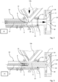
- the Figures 1 to 3 show at least parts of a mixing arrangement, designated as a whole by 1, for mixing solids in liquids.
- the mixing arrangement 1 comprises a mixing device 2 and a solids supply device 3 connected thereto. Solids, for example powder, can be supplied to the mixing device 2 via the solids supply device 3 .
- the mixing device 2 shown in the figures is a solid-liquid mixing device.
- the mixing device 2 is supplied with liquid into which the solid is to be mixed via a connection which is not shown.
- the mixing device 2 has a solids inlet 4 to which the solids supply device 3 is connected.
- the solids supply device 3 serves to supply the mixing device 2 with solids, in particular bulk material, for example powder.
- the solids feeding device 3 has a funnel 5 .
- the funnel 5 is used to hold solids.
- an emptying device 6 is arranged above the funnel 5 . Solids from big bags can be filled into the funnel 5 of the solids feed device 3 with the aid of this emptying device 6 .
- the solids supply device 3 also has a solids outlet 7, which can be connected to the previously mentioned solids inlet 4 of the mixing device 2 and according to the Figures 1 to 3 connected is.
- the solids outlet 7 of the solids supply device 3 is connected to the hopper 5 via a conveying connection 8 .
- the solids feed device 3 has a slide 9 which can be moved between a first end position (cf. figure 2 ) and a second end position (cf. figure 3 ) is movable through the conveyor connection 8.
- the distance between the two end positions is selected in such a way that the slide 9 can be moved through the entire conveying path of the conveying connection 8 .
- a protrusion that the slide 9 has in its second end position in relation to the solids outlet 7 is as large as a distance between an inlet cross section 21 into the solids inlet 4 and a discharge cross section 18 of the solids inlet 4 into a mixing chamber 19 of the mixing device connected to the solids feed device 3 2.
- the solids inlet 4 of the mixing device 2 is designed as a pipe socket.
- the slider 9 of the solids feed device 3 is a piston of a piston valve 10.
- the piston valve 10 is located downstream of the funnel 5 of the solids feed device 3 in the conveying direction of the solids through the solids feed device 3.
- the piston valve 10 has a housing 11 .
- the housing 11 not only forms the entire conveying connection 8 between the hopper 5 and the solids outlet 7 of the solids feed device 3 , but also has the solids outlet 7 .
- the funnel 5 includes a funnel outlet 12 which opens directly into the housing 11 of the piston valve 10 .
- a junction 13 of the funnel outlet 12 in the housing 11 of the piston valve 10 is arranged between the first end position and the second end position of the slide 9 .
- the funnel outlet 12 is arranged inside the conveyor connection 8, i.e. inside the housing 11.
- the opening 13 of the funnel outlet 12 is at least partially enclosed by the housing 11.
- the slide 9 can be moved through the opening 13 of the funnel outlet 12 .
- the housing 11 is connected directly to the funnel 5 as a result.
- the solids supply device 3 also includes a solids aerator 14 which ensures within the hopper 5 that the solids therein are loosened sufficiently and therefore remains fluid.
- the solids loosening device 14 has a drive 15 .
- About the drive 15 can in the Figures 2 and 3 wings 14a shown in section of the solids agitator 14 are rotated within the hopper 5 in order to aerate solids therein or keep them loose.
- An axis of rotation R of the solids aerator 14 is in figure 1 implied.
- the solids feed device 3 has a slide drive 16 .
- the slide drive 16 can be designed, for example, as a pneumatic or as an electric slide drive.
- Pneumatic or electric slide valve drives are particularly suitable for applications in the food and/or pharmaceutical sector due to the hygienic requirements there. In principle, the use of hydraulic slide drives would also be conceivable.
- the slide drive 16 is connected to the slide 9 via a spindle 17 .
- the slide 9 can be moved back and forth between the first end position and the second end position with the aid of the spindle 17 .
- the slide drive 16 can also have a gear, not shown in the figures, which can preferably be designed as a reduction gear. The slide drive 16 is then connected to the spindle 17 via the gear.
- FIG. 2 and 3 illustrate that the solids outlet 7 of the solids supply device 3 is connected to the solids inlet 4 of the mixing device 2 .
- the solids inlet 4 has an opening cross section 18 directly into a mixing chamber 19 of the mixing device 2 . Solids supplied via the solids inlet 4 can be introduced directly into the mixing chamber 19 of the mixing device 2 via this opening cross section 18 .
- An end face 20 of the slide 9 closes the opening cross section 18 of the solids inlet 4 flush with the wall when the slide 9 moves according to its second end position figure 3 has reached. In this way, it is ensured that the entire conveying distance, which is provided by the conveying connection 8, the solids outlet 7 and the solids inlet 4, can be covered by the slide 9 and, if necessary, freed from adhesions.
- figure 3 clarifies that a protrusion that the slide 9 has in its second end position relative to the solids outlet 7 is as large as a distance between an entry cross section 21 into the solids inlet 4 and the opening cross section 18 of the solids inlet 4 into the mixing chamber 19.
- the solids supply device 3 has a monitoring device 23 .
- the monitoring device 23 is set up to detect a blockage in the conveying connection 8 .
- the monitoring device 23 can be connected to a monitoring sensor 24 in the form of a pressure sensor.
- the monitoring sensor 24 can be arranged in the mixing chamber 19 of the mixing device 2 or also in the conveying connection 8 .
- the rotor-stator unit 22 of the mixing device 2 is set up to generate a negative pressure in the mixing chamber 19 .
- the solid is conveyed through the conveying connection 8 of the solid supply device 3 into the mixing chamber 19 of the mixing device 2 by the negative pressure. Once the conveyor connection 8 is clogged by buildup of solids, the Monitoring sensor 24 detect a drop in pressure in the mixing chamber 19 or in the delivery connection 8 .
- the monitoring device 23 can also monitor a power consumption of a drive of the rotor-stator unit 22 . If a drop in the power consumption of the drive can be detected, this can indicate a blockage in the conveying connection 8 and the slide 9 can be activated.
- the mixing arrangement 1 and the solids feed device 3 are set up to carry out the method described below:
- solids for example bulk material in the form of a powder
- the solids enter the mixing device 2 via the conveying connection 8 of the solids supply device 3 and here in particular into the mixing chamber 19 of the mixing device 2 .
- the solids supply device 3 has the slide 9 , as already explained above. This can be moved between its first end position and its second end position by the conveyor connection 8 and is set up to loosen the buildup of solid matter within the conveyor connection 8 .
- the slide 9 is activated and moved through the conveyor connection 8 to clear the conveyor connection 8 as soon as the conveyor connection 8 between the solids outlet 7 and the hopper 5 is blocked.
- the slide drive 16 is controlled and activated accordingly.
- the solid is conveyed, namely sucked in, into the mixing chamber 19 of the mixing device 2 with the aid of negative pressure.
- the Negative pressure, with which the solid is sucked in, is generated with the aid of the rotor-stator unit 22 of the mixing device 2 .
- the conveyor connection 8 is monitored for blockages with the monitoring device 23 of the solids feed device 3 .
- the monitoring device 23 activates the slide 9 at least indirectly as soon as a blockage of the conveying connection 8 is detected. In this way, the method can be carried out automatically.
- the blockage of the conveyor connection 8 can be detected, for example, based on a drop in power consumption of a drive of the rotor-stator unit 22 . It is also possible to detect the blockage of the delivery connection 8 based on a pressure change in the delivery connection 8 and/or in the mixing chamber 19 of the mixing device 2 .
- One or more monitoring sensors 24 of the monitoring device 23 embodied, for example, as pressure sensors can be used for this purpose.
- the invention addresses improvements in the art of feeding solids to mixing devices.
- the solids feed device 3 is proposed for this purpose.
- This has the slide 9 which can be moved between a first end position and a second end position by a conveyor connection 8 which is arranged between a hopper 5 and a solids outlet 7 of the solids feed device 3 .
- a conveyor connection 8 which is arranged between a hopper 5 and a solids outlet 7 of the solids feed device 3 .
Description
Die Erfindung betrifft ein Verfahren zur Zuführung von Feststoff zu einer Mischvorrichtung unter Verwendung einer Feststoffzuführvorrichtung. Ferner betrifft die Erfindung eine Feststoffzuführvorrichtung zum Zuführen von Feststoff, insbesondere von Schüttgut, wie zum Beispiel Pulver, zu einer Mischvorrichtung, wobei die Feststoffzuführvorrichtung einen Trichter zur Aufnahme von Feststoff und einen Feststoffauslass aufweist, der mit einem Feststoffeinlass einer Mischvorrichtung verbindbar ist, wobei der Feststoffauslass und der Trichter über eine Förderverbindung miteinander verbunden sind.The invention relates to a method for feeding solids to a mixing device using a solids feeding device. The invention also relates to a solids feed device for feeding solids, in particular bulk material, such as powder, to a mixing device, the solids feed device having a hopper for receiving solids and a solids outlet which can be connected to a solids inlet of a mixing device, the solids outlet and the hopper are connected to each other via a conveyor connection.
Die Erfindung betrifft ferner eine Mischanordnung mit zumindest einer Mischvorrichtung und zumindest einer Feststoffzuführvorrichtung sowie die Verwendung einer Feststoffzuführvorrichtung und/oder einer Mischanordnung bei einem Verfahren der eingangs genannten Art.The invention also relates to a mixing arrangement with at least one mixing device and at least one solids supply device and the use of a solids supply device and/or a mixing arrangement in a method of the type mentioned at the outset.
Feststoffzuführvorrichtungen sind aus der Praxis und auch dem druckschriftlichen Stand der Technik, so zum Beispiel aus den Druckschriften
Die Mischvorrichtungen, die zusammen mit derartigen Feststoffzuführvorrichtungen in so genannten Mischanordnungen betrieben werden, sind häufig Fest-Flüssig-Mischvorrichtungen, die dazu verwendet werden, Feststoffe in eine Flüssigkeit einzubringen und möglichst gleichmäßig mit dieser zu vermischen.The mixing devices that are operated together with such solids feed devices in so-called mixing arrangements are often solid-liquid mixing devices that are used to introduce solids into a liquid and mix it with it as uniformly as possible mix.
Zur Feststoffaufgabe, also um die Feststoffe der Feststoffzuführvorrichtung zu übergeben, werden häufig sogenannte Sauglanzen, Sackschütten oder Big-Bag-Entleerstationen verwendet.So-called suction lances, sack chutes or big-bag emptying stations are often used to feed the solids, i.e. to transfer the solids to the solids feed device.
Mithilfe der Feststoffzuführvorrichtungen werden die Feststoffe dann den nachgelagert angeordneten Mischvorrichtungen zugeführt. Je nach Fließeigenschaften der zuzuführenden Feststoffe gelingt diese Zuführung mal besser mal schlechter. Bei gut fließenden Feststoffen oder Pulvern gelingt die Zuführung in der Regel problemlos. Es gibt aber auch andere Feststoffe, insbesondere Pulver, die schlechte Fließeigenschaften haben und ein Verstopfen der an der Zuführung beteiligten Elemente der Feststoffzuführvorrichtungen begünstigen.The solids are then fed to the downstream mixing devices with the aid of the solids feed devices. Depending on the flow properties of the solids to be fed, this feed is sometimes better or worse. In the case of free-flowing solids or powders, the feed usually succeeds without any problems. However, there are also other solids, in particular powders, which have poor flow properties and promote clogging of the elements of the solids feed devices involved in the feed.
Besonders problematisch ist die Zuführung schlecht fließender Pulver, Pulver, die zur Brückenbildung neigen, Pulver, die zum Kompaktieren neigen, oder auch die Zuführung stumpfer und anhaftender Pulver, wie z.B. Titandioxid.Feeding powders that flow poorly, powders that tend to bridge, powders that tend to compact, or feed powders that are dull and sticky, such as titanium dioxide, is particularly problematic.
Zum Lösen von Anhaftungen oder Brücken im Bereich des Trichters einer solchen Feststoffzuführvorrichtung ist es beispielsweise bekannt, pneumatische Klopfer oder Vibratoren einzusetzen. Mit diesen vorbekannten Maßnahmen lassen sich auch schwierigste Feststoffe derart auflockern, dass Anhaftungen und Verstopfungen im Bereich des Trichters weitgehend vermieden werden können.To loosen adhesions or bridges in the area of the funnel of such a solids feed device, it is known, for example, to use pneumatic beaters or vibrators. With these previously known measures, even the most difficult solids can be loosened in such a way that adhesions and blockages in the area of the hopper can be largely avoided.
Die dem Trichter nachgelagerte Förderverbindung wird von den Vibrationen und Erschütterungen, die durch solche Klopfer und Vibratoren auf den Trichter übertragen werden, in der Regel nicht erfasst. Problematisch bleibt somit die Zuführung von Feststoffen durch die Förderverbindung, die zwischen dem Trichter und dem Feststoffauslass der Feststoffzuführvorrichtung notwendig ist. Mit den bisher bekannten Konzepten können Feststoffanhaftungen innerhalb der Förderverbindung zwischen dem Trichter und dem Feststoffauslass der Feststoffzuführvorrichtungen nicht zufriedenstellend verhindert und schon gar nicht gelöst werden.The conveyor connection downstream of the hopper is generally not affected by the vibrations and shocks that are transmitted to the hopper by such knockers and vibrators. The supply of remains problematic Solids through the conveyor connection that is necessary between the hopper and the solids outlet of the solids feeder. With the concepts known up to now, it is not possible to satisfactorily prevent, let alone solve, the accumulation of solids within the conveying connection between the funnel and the solids outlet of the solids feed devices.
Aufgabe der Erfindung ist es daher, ein Verfahren, eine Feststoffzuführvorrichtung und eine Mischanordnung der eingangs genannten Art bereitzustellen, die die zuvor genannten Probleme vermeiden und die Zuführung von Feststoffen vereinfachen.The object of the invention is therefore to provide a method, a solids supply device and a mixing arrangement of the type mentioned at the outset which avoid the aforementioned problems and simplify the supply of solids.
Zur Lösung der Aufgabe wird zunächst ein Verfahren mit den Mitteln und Merkmalen des unabhängigen, auf ein Verfahren zur Zuführung von Feststoff zu einer Mischvorrichtung gerichteten Anspruchs vorgeschlagen. Insbesondere wird zur Lösung der Aufgabe somit ein Verfahren zur Zuführung von Feststoff, beispielsweise von Schüttgut, wie Pulver, zu einer Mischvorrichtung unter Verwendung einer Feststoffzuführvorrichtung vorgeschlagen. Die Feststoffzuführvorrichtung umfasst einen Trichter zur Aufnahme von Feststoff und einen Feststoffauslass, der mit einem Feststoffeinlass der Mischvorrichtung, der der Feststoff zugeführt werden soll, verbunden ist. Der Feststoffauslass und der Trichter sind über eine Förderverbindung der Feststoffzuführvorrichtung miteinander verbunden. Der Feststoff wird über die Förderverbindung der Mischvorrichtung, hier insbesondere einer Mischkammer der Mischvorrichtung, zugeführt. Die Feststoffzuführvorrichtung weist einen Schieber auf, der zwischen einer ersten Endposition und einer zweiten Endposition durch die Förderverbindung bewegt werden kann und dazu eingerichtet ist, Anhaftungen von Feststoff innerhalb der Förderverbindung zu lösen. Erfindungsgemäß wird der Schieber aktiviert und durch die Förderverbindung bewegt, um die Förderverbindung freizuräumen, sobald die Förderverbindung zwischen dem Feststoffauslass und dem Trichter verstopft ist.In order to solve the problem, a method with the means and features of the independent claim directed to a method for feeding solids to a mixing device is first proposed. In order to achieve the object, a method for feeding solids, for example bulk material such as powder, to a mixing device using a solids feeding device is therefore proposed in particular. The solids feeding device comprises a hopper for receiving solids and a solids outlet which is connected to a solids inlet of the mixing device to which the solids are to be fed. The solids outlet and the hopper are connected to one another via a conveyor connection of the solids feed device. The solid is fed via the conveying connection to the mixing device, here in particular to a mixing chamber of the mixing device. The solids supply device has a slide which can be moved between a first end position and a second end position by the conveyor connection and is set up to buildup of solids within the to release the delivery connection. According to the invention, the slide is activated and moved through the conveyor connection to clear the conveyor connection as soon as the conveyor connection between the solids outlet and the hopper is blocked.
Anhaftungen von Feststoff, die sich innerhalb der Förderverbindung der Feststoffzuführvorrichtung festsetzen können, lassen sich so besonders einfach und ohne eine Demontage der Förderverbindung entfernen.Adhesion of solids that can become lodged within the conveyor connection of the solids feed device can thus be removed particularly easily and without dismantling the conveyor connection.
Bei einer Ausführungsform des Verfahrens ist vorgesehen, den Feststoff mit Hilfe von Unterdruck in die Mischvorrichtung, hier insbesondere in eine Mischkammer der Mischvorrichtung, zu fördern, beispielsweise einzusaugen. Der Unterdruck, mit dem der Feststoff der Mischvorrichtung zugeführt werden kann, kann beispielsweise mit einer Rotor-Stator-Einheit der Mischvorrichtung erzeugt werden. Die Rotor-Stator-Einheit kann in einer, beispielsweise in der bereits zuvor erwähnten Mischkammer der Mischvorrichtung angeordnet sein.One embodiment of the method provides for the solid to be conveyed, for example sucked, into the mixing device, here in particular into a mixing chamber of the mixing device, with the aid of negative pressure. The negative pressure with which the solids can be fed to the mixing device can be generated, for example, with a rotor-stator unit of the mixing device. The rotor-stator unit can be arranged in one, for example in the previously mentioned mixing chamber of the mixing device.
Mit Hilfe des Unterdrucks kann der Feststoff durch die Förderverbindung der Feststoffzuführvorrichtung in die Mischkammer der Mischvorrichtung eingesaugt werden. Während der Zuführung des Feststoffes durch die Förderverbindung in die Mischkammer kann zwischen der Mischkammer der Mischvorrichtung und dem Trichter der Feststoffzuführvorrichtung eine durchgängige Druckverbindung geöffnet sein, die durch den Schieber nicht beeinträchtigt wird. Erst im Falle einer Verstopfung der Förderverbindung wird der Schieber aktiviert und zum Freiräumen der Förderverbindung durch die Förderverbindung bewegt.With the aid of the negative pressure, the solid can be sucked into the mixing chamber of the mixing device through the conveying connection of the solid supply device. During the supply of the solid through the conveying connection into the mixing chamber, a continuous pressure connection can be opened between the mixing chamber of the mixing device and the hopper of the solid supply device, which is not affected by the slide. Only in the event of a blockage in the conveyor connection is the slide activated and moved through the conveyor connection to clear the conveyor connection.
Verstopfungen der Förderverbindung werden erfindungsgemäß mit einer Überwachungsvorrichtung detektiert. Die Überwachungsvorrichtung kann eine Überwachungsvorrichtung der Feststoffzuführvorrichtung sein. Die Überwachungsvorrichtung aktiviert den Schieber, insbesondere einen Schieberantrieb der Feststoffzuführvorrichtung, zumindest mittelbar, sobald eine Verstopfung der Förderverbindung detektiert wird. Auf diese Weise ist eine automatisierte Durchführung des Verfahrens möglich. Sobald eine Verstopfung der Förderverbindung von der Überwachungsvorrichtung festgestellt wird, kann diese den Schieber, insbesondere einen Schieberantrieb, automatisch zumindest mittelbar aktivieren, wodurch der Schieber durch die Förderverbindung bewegt wird, um etwaige Verstopfungen zu lösen und die Förderverbindung von Anhaftungen zu befreien.According to the invention, blockages in the conveying connection are detected with a monitoring device. The monitoring device can be a monitoring device be solid feeder. The monitoring device activates the slide, in particular a slide drive of the solids feed device, at least indirectly as soon as a blockage of the conveyor connection is detected. In this way, an automated implementation of the method is possible. As soon as the monitoring device detects a blockage in the conveyor connection, it can automatically activate the slide, in particular a slide drive, at least indirectly, causing the slide to be moved through the conveyor connection in order to loosen any blockages and free the conveyor connection from buildup.
Bei einer Ausführungsform des Verfahrens kann eine Verstopfung der Förderverbindung anhand eines Abfalls einer Leistungsaufnahme eines Antriebs der Rotor-Stator-Einheit der Mischvorrichtung detektiert werden. Ergänzend oder alternativ dazu ist es auch möglich, eine Verstopfung der Förderverbindung mit einem Überwachungssensor der Überwachungsvorrichtung zu detektieren. Bei einer Ausführungsform des Verfahrens wird eine Verstopfung der Förderverbindung anhand einer Druckänderung in der Mischvorrichtung, insbesondere anhand einer Druckänderung in der Mischkammer der Mischvorrichtung detektiert. Dazu kann beispielsweise ein Überwachungssensor in Form eines Drucksensors verwendet werden, der in der Mischkammer oder im Bereich der Mischkammer oder in der Förderverbindung angeordnet ist. Ist die Förderverbindung verstopft, kann mit dem Drucksensor ein Druckabfall registriert werden. Ein definierter Druckabfall, beispielsweise in der Mischkammer, kann auf eine Verstopfung der Förderverbindung hinweisen. Ein von einem entsprechenden Überwachungssensor generiertes Sensorsignal kann von der Überwachungsvorrichtung genutzt werden, den Schieber, insbesondere einen Schieberantrieb, zumindest mittelbar zu aktivieren, um den Schieber durch die Förderverbindung zu bewegen. So können die Förderverbindung bei Verstopfungen automatisiert freigeräumt und das Verfahren automatisiert durchgeführt werden.In one embodiment of the method, a blockage of the delivery connection can be detected based on a drop in power consumption of a drive of the rotor-stator unit of the mixing device. In addition or as an alternative to this, it is also possible to use a monitoring sensor of the monitoring device to detect a blockage in the delivery connection. In one embodiment of the method, a blockage of the delivery connection is detected based on a pressure change in the mixing device, in particular based on a pressure change in the mixing chamber of the mixing device. A monitoring sensor in the form of a pressure sensor can be used for this purpose, for example, which is arranged in the mixing chamber or in the area of the mixing chamber or in the delivery connection. If the delivery connection is blocked, a pressure drop can be registered with the pressure sensor. A defined drop in pressure, for example in the mixing chamber, can indicate a blockage in the delivery connection. A sensor signal generated by a corresponding monitoring sensor can be used by the monitoring device to at least indirectly activate the slide, in particular a slide drive, in order to move the slide through the conveyor connection. So can the conveyor connection cleared automatically in the event of blockages and the process can be carried out automatically.
Zur Lösung dieser Aufgabe wird ferner eine Feststoffzuführvorrichtung mit den Merkmalen des unabhängigen, auf eine solche Feststoffzuführvorrichtung gerichteten Anspruchs vorgeschlagen. Die Aufgabe wird somit insbesondere dadurch gelöst, dass die Feststoffzuführvorrichtung einen Schieber aufweist, der zwischen einer ersten Endposition und einer zweiten Endposition durch die Förderverbindung bewegbar ist.To solve this problem, a solids feed device is also proposed with the features of the independent claim directed to such a solids feed device. The object is thus achieved in particular in that the solids feed device has a slide which can be moved between a first end position and a second end position by the conveyor connection.
Mithilfe des Schiebers können die zuvor beschriebenen Anhaftungen von Feststoff innerhalb der Förderverbindung zuverlässig vermieden und/oder gelöst werden. Sobald festgestellt wird, dass die Förderverbindung zwischen dem Feststoffauslass und dem Trichter der Feststoffzuführvorrichtung verstopft ist, kann der Schieber aktiviert und durch seine Bewegung zwischen den beiden Endpositionen zum Freiräumen der Förderverbindung verwendet werden. Um den Schieber zwischen seinen Endpositionen durch die Förderverbindung zu bewegen, kann ein Schieberantrieb der Feststoffzuführvorrichtung aktiviert werden.With the aid of the slide, the above-described buildup of solid matter within the conveying connection can be reliably avoided and/or detached. As soon as it is determined that the conveyor connection between the solids outlet and the hopper of the solids feeder is blocked, the slide can be activated and used by moving it between the two end positions to clear the conveyor connection. In order to move the slide between its end positions through the conveyor connection, a slide drive of the solids feed device can be activated.
In der ersten Endposition kann der Schieber die Förderverbindung freigeben, während er die Förderverbindung in der zweiten Endposition verschließen kann. Verschließt der Schieber die Förderverbindung, wird ein Feststoffvorrat innerhalb der Feststoffzuführvorrichtung von nachgelagerten Bereichen, insbesondere von einer Mischkammer einer mit der Feststoffzuführvorrichtung verbundenen Mischvorrichtung räumlich getrennt. So kann mit dem Schieber verhindert werden, dass der Feststoff mit einer in der Mischvorrichtung vorhandenen oder zirkulierenden Flüssigkeit in Kontakt gerät.In the first end position, the slide can release the conveyor connection, while in the second end position it can close the conveyor connection. If the slide closes the conveying connection, a supply of solids within the solids supply device is spatially separated from downstream areas, in particular from a mixing chamber of a mixing device connected to the solids supply device. The slide can thus be used to prevent the solid from coming into contact with a liquid that is present or circulating in the mixing device.
Der Trichter kann auch ganz allgemein und entsprechend seiner Funktion als Feststoffaufahmeelement der Feststoffzuführvorrichtung bezeichnet werden. Er dient dazu, Feststoff aus einem vorgelagerten Abschnitt, zum Beispiel aus einer Schütte und/oder aus einem Vorratssack aufzunehmen und den nachgelagerten Förderabschnitten der Förderzuführvorrichtung zuzuführen.The funnel can also be referred to quite generally and in accordance with its function as a solids receiving element of the solids feed device. It is used to pick up solids from an upstream section, for example from a chute and/or from a storage bag, and to feed them to the downstream conveyor sections of the conveyor feed device.
Besonders vorteilhaft ist es, wenn der Schieber einen lichten Querschnitt der Förderverbindung und/oder des Feststoffauslasses ausfüllt. Auf diese Weise ist es möglich, den gesamten lichten Querschnitt der Förderverbindung und/oder des Feststoffauslasses der Feststoffzuführvorrichtung mit dem Schieber zu erfassen und dort gegebenenfalls anhaftendes Material abzulösen.It is particularly advantageous if the slide fills an open cross section of the conveying connection and/or the solids outlet. In this way, it is possible to cover the entire clear cross-section of the conveyor connection and/or the solids outlet of the solids feed device with the slide and to detach any material adhering there.
Um sicherzustellen, dass die Förderverbindung und auch der Feststoffauslass vollständig mit dem Schieber erfasst werden können, ist es vorteilhaft, wenn der Schieber in seiner zweiten Endposition aus dem Feststoffauslass herausragt und/oder einen Überstand zu dem Feststoffauslass aufweist. Auf diese Weise kann selbst im Bereich des Feststoffauslasses anhaftendes Material sicher von dem Schieber erfasst und abgelöst werden.In order to ensure that the conveyor connection and also the solids outlet can be completely grasped by the slide, it is advantageous if the slide protrudes from the solids outlet in its second end position and/or has a projection from the solids outlet. In this way, material adhering even in the area of the solids outlet can be reliably grasped and detached by the slide.
Besonders vorteilhaft kann es sein, wenn der Überstand, den der Schieber in seiner zweiten Endposition zu dem Feststoffauslass aufweist, so groß wie eine Distanz zwischen einem Eintrittsquerschnitt in einen Feststoffeinlass und einem Mündungsquerschnitt des Feststoffeinlasses in eine Mischkammer einer mit der Feststoffzuführvorrichtung verbindbaren Mischvorrichtung ist.It can be particularly advantageous if the overhang that the slide has in its second end position in relation to the solids outlet is as large as a distance between an entry cross section into a solids inlet and a discharge cross section of the solids inlet into a mixing chamber of a mixing device that can be connected to the solids feed device.
Bei einer besonders vorteilhaften Ausführungsform der Feststoffzuführvorrichtung ist vorgesehen, dass der Schieber ein Kolben eines Kolbenventils ist. Dieses Kolbenventil kann dem Trichter in Förderrichtung des Feststoffs durch die Feststoffzuführvorrichtung nachgelagert sein.In a particularly advantageous embodiment of the solids feed device, it is provided that the slide is a piston of a piston valve. This piston valve can be located downstream of the funnel in the conveying direction of the solid through the solid supply device.
Das Kolbenventil kann ein Gehäuse aufweisen, das zumindest einen Abschnitt der Förderverbindung zwischen dem Trichter und dem Feststoffauslass bildet. Besonders vorteilhaft ist es, wenn das Kolbenventil ein Gehäuse aufweist, das die gesamte Förderverbindung zwischen dem Trichter und dem Feststoffauslass bildet. Auch der Feststoffauslass kann an dem Gehäuse des zuvor erwähnten Kolbenventils angeordnet oder ausgebildet sein.The piston valve may have a housing that forms at least a portion of the delivery connection between the funnel and the solids outlet. It is particularly advantageous if the piston valve has a housing that forms the entire delivery connection between the funnel and the solids outlet. The solids outlet can also be arranged or formed on the housing of the aforementioned piston valve.
Der Trichter der Feststoffzuführvorrichtung kann einen Trichterauslass aufweisen, der in die Förderverbindung mündet. Wenn die Förderverbindung zumindest zum Teil von einem, beispielsweise dem bereits zuvor erwähnten, Gehäuse eines, beispielsweise des bereits zuvor erwähnten, Kolbenventils gebildet ist, kann der Trichterauslass auch direkt in das Gehäuse des Kolbenventils münden.The hopper of the solids feeder can have a hopper outlet which opens into the conveyor connection. If the delivery connection is formed at least in part by a housing, for example the one already mentioned above, of a piston valve, for example the one already mentioned above, the funnel outlet can also open directly into the housing of the piston valve.
Dabei kann eine Einmündung des Trichterauslasses in das Gehäuse zwischen der ersten Endposition und der zweiten Endposition des Schiebers angeordnet sein. So gelangt der Feststoff auf direktem Wege aus dem Trichter in die Förderverbindung zwischen dem Trichter und dem Feststoffauslass der Feststoffzuführvorrichtung. Aufgrund der Anordnung der Einmündung des Trichterauslasses in das Gehäuse zwischen der ersten Endposition und der zweiten Endposition des Schiebers kann sichergestellt werden, dass der gesamte, mit Feststoff in Berührung kommende Bereich der Förderverbindung der Feststoffzuführvorrichtung zwischen dem Trichter und dem Feststoffauslass von dem Schieber erfasst und freigeräumt werden kann.A junction of the funnel outlet into the housing can be arranged between the first end position and the second end position of the slide. In this way, the solids go directly from the hopper into the conveying connection between the hopper and the solids outlet of the solids feed device. Due to the arrangement of the confluence of the funnel outlet in the housing between the first end position and the second end position of the slide, it can be ensured that the entire area of the conveyor connection of the solids feed device that comes into contact with solids between the funnel and the solids outlet is grasped by the slide and cleared can be.
In einer weiteren Ausgestaltung der Erfindung ist der Trichterauslass innerhalb der Förderverbindung angeordnet und der Schieber ist durch die Einmündung hindurch bewegbar. In dieser Ausgestaltung ist der Trichterauslass ohne weitere Zwischenverbindungen direkt mit der Förderverbindung verbunden. Der Schieber ist durch den Trichterauslass hindurch zwischen der ersten und der zweiten Endposition bewegbar. Dadurch könne etwaige Pulverbrücken im Trichterauslass durch den Schieber ausgeräumt werden. Verstopfungen werden so vermieden. Des Weiteren ist der Feststoff, der sich vor der Zuführung zu der Förderverbindung in dem Trichter befindet, stets durch z.B. einen Rührflügel des Auflockerers bewegbar, so dass sich auch kurz vor dem Eintritt des Feststoffes in die Förderverbindung keine Pulverbrücken oder Verstopfungen bilden können. Es ist somit kein "Totraum" vorhanden, d.h. es gibt keine Stellen in der Feststoffzuführvorrichtung, die nicht von dem Auflockerer oder dem Schieber erreicht und somit mechanisch von Verstopfungen befreit werden könnten.In a further embodiment of the invention, the funnel outlet is arranged within the conveyor connection and the slide can be moved through the junction. In this embodiment, the funnel outlet is connected directly to the conveying connection without any further intermediate connections. The slide can be moved through the funnel outlet between the first and the second end position. As a result, any powder bridges in the funnel outlet can be cleared by the slide. Blockages are avoided in this way. Furthermore, the solid, which is in the hopper before it is fed to the conveyor connection, can always be moved, for example, by a stirring blade of the agitator, so that no powder bridges or blockages can form even just before the solid enters the conveyor connection. There is therefore no "dead space", i.e. there are no points in the solids feed device which cannot be reached by the aerator or the slide and thus mechanically freed from blockages.
Um potentielle Anhaftungen von Feststoff in der gesamten Förderstrecke, die von der Feststoffzuführvorrichtung bereitgestellt wird, vermeiden oder lösen zu können, kann die Feststoffzuführvorrichtung ferner einen Feststoffauflockerer und/oder einen Fluidisator und/oder einen Vibrator und/oder einen Klopfer, insbesondere einen pneumatischen Klopfer, aufweisen. Diese zuvor erwähnten, zur Vermeidung und/oder Lösung von Anhaftungen vorgesehenen Funktionseinheiten der Feststoffzuführvorrichtung können insbesondere in oder an dem Trichter angeordnet oder ausgebildet sein.In order to be able to avoid or loosen potential buildup of solids in the entire conveying section provided by the solids feed device, the solids feed device can also have a solids loosening device and/or a fluidizer and/or a vibrator and/or a beater, in particular a pneumatic beater. exhibit. These above-mentioned functional units of the solids feed device, which are provided for avoiding and/or loosening adhesions, can be arranged or formed in particular in or on the hopper.
Unter einem Fluidisator versteht man ein Funktionselement, das zur Auflockerung von Feststoff, insbesondere von Pulver verwendet wird. Dabei ist der Fluidisator dazu eingerichtet, Luft in ein Förderelement, zum Beispiel eine Rohrleitung und/oder den bereits zuvor erwähnten Trichter, der Feststoffzuführvorrichtung einzublasen, um dort vorhandenen Feststoff, insbesondere Pulver, aufzulockern und/oder zu lösen. Auf diese Weise kann der Feststoff, insbesondere das Pulver, derart aufgelockert werden, dass er/es leichter fließt und leichter durch die Feststoffzuführvorrichtung bewegt werden kann. Auch hierbei kann der zuvor erwähnte Fluidisator vorzugsweise im Bereich des Trichters der Feststoffzuführvorrichtung angeordnet oder ausgebildet sein.A fluidizer is a functional element that is used to loosen solids, especially powder. In this case, the fluidizer is set up to air in a conveying element, for example a pipeline and / or the previously mentioned funnel, the Inject solids feeder to loosen and / or solve existing solids, especially powder. In this way, the solid, in particular the powder, can be loosened up in such a way that it flows more easily and can be moved more easily through the solids feed device. In this case, too, the previously mentioned fluidizer can preferably be arranged or formed in the region of the funnel of the solids feed device.
Ferner können die mit dem zuzuführenden Feststoff in Kontakt tretenden Elemente der Feststoffzuführvorrichtung, also insbesondere der zuvor erwähnte Trichter sowie die zuvor erwähnte Förderverbindung und auch der Feststoffauslass der Feststoffzuführvorrichtung, mit einer Antihaftbeschichtung versehen sein oder aus Werkstoffen bestehen, die eine vergleichsweise geringe Anhaftwirkung auf zuzuführende Feststoffe aufweisen.Furthermore, the elements of the solids feed device that come into contact with the solids to be fed, i.e. in particular the aforementioned funnel and the aforementioned conveyor connection and also the solids outlet of the solids feed device, can be provided with a non-stick coating or consist of materials that have a comparatively low adhesion effect on the solids to be fed exhibit.
Die Feststoffzuführvorrichtung kann außerdem einen Schieberantrieb aufweisen. Der Schieberantrieb dient dazu, den Schieber zwischen der ersten Endposition und der zweiten Endposition hin und her zu bewegen. Dabei kann der Schieberantrieb ein pneumatischer und/oder elektrischer Schieberantrieb sein.The solids feed device can also have a slide drive. The slider drive serves to move the slider back and forth between the first end position and the second end position. The slide drive can be a pneumatic and/or electric slide drive.
Besonders vorteilhaft ist es, wenn der zuvor erwähnte Schieberantrieb eine Spindel aufweist, mit der der Schieber zwischen der ersten Endposition und der zweiten Endposition verschiebbar ist. Die Verwendung einer Spindel hat den Vorteil, dass der Schieber mit vergleichsweise hoher und vor allem gleichmäßiger Kraft durch die Förderverbindung zwischen dem Feststoffauslass und dem Trichter hin und her bewegt werden kann. Auf diese Weise lassen sich auch hartnäckige Anhaftungen innerhalb der Förderverbindung lösen, die nur mit vergleichsweise hohem Kraftaufwand gelöst werden können.It is particularly advantageous if the aforementioned slide drive has a spindle with which the slide can be displaced between the first end position and the second end position. The use of a spindle has the advantage that the slide can be moved back and forth with a comparatively high and, above all, uniform force through the conveying connection between the solids outlet and the funnel. In this way, even stubborn buildup within the conveyor connection can be loosened, which can only be loosened with a comparatively large amount of force.
Ferner ist es möglich, dass der Schieberantrieb ein Getriebe, insbesondere ein Untersetzungsgetriebe, aufweist, das mit einer, insbesondere der zuvor erwähnten, Spindel verbunden ist. Die Verwendung eines Untersetzungsgetriebes hat den Vorteil, dass die Kraft, mit der der Schieber durch die Förderverbindung bewegt werden kann, vergleichsweise einfach erhöht werden kann. So kann der Schieberantrieb entsprechend klein oder schwach dimensioniert sein, ohne dass es zu Krafteinbußen bei der Betätigung des Schiebers kommen muss.It is also possible for the slide drive to have a gear, in particular a reduction gear, which is connected to a spindle, in particular to the spindle mentioned above. The use of a reduction gear has the advantage that the force with which the slide can be moved through the conveyor connection can be increased comparatively easily. The slide drive can thus be correspondingly small or weakly dimensioned, without there having to be a loss of force when the slide is actuated.
Erfindungsgemäß weist die Feststoffzuführvorrichtung eine Überwachungsvorrichtung auf, die zur Detektion einer Verstopfung der Förderverbindung eingerichtet ist. Ferner kann die Feststoffzuführvorrichtung, insbesondere ihre Überwachungsvorrichtung, einen Überwachungssensor aufweisen, mit dem etwaige Verstopfungen der Förderverbindung zumindest mittelbar detektiert werden können. Der Überwachungssensor kann ein Drucksensor sein, der in Gebrauchsstellung beispielsweise in der Förderverbindung oder in einer Mischkammer der Mischvorrichtung, an die die Feststoffzuführvorrichtung angeschlossen ist, angeordnet sein kann.According to the invention, the solids feed device has a monitoring device which is set up to detect a blockage in the conveying connection. Furthermore, the solids feed device, in particular its monitoring device, can have a monitoring sensor with which any blockages in the conveying connection can be detected at least indirectly. The monitoring sensor can be a pressure sensor which, when in use, can be arranged, for example, in the conveying connection or in a mixing chamber of the mixing device to which the solids supply device is connected.
Die zuvor erläuterte Feststoffzuführvorrichtung ist zur Durchführung des Verfahrens nach einem der auf ein Verfahren zur Zuführung von Feststoff zu einer Mischvorrichtung gerichteten Ansprüche eingerichtet.The solids supply device explained above is set up for carrying out the method according to one of the claims directed to a method for supplying solids to a mixing device.
Zur Lösung der Aufgabe wird auch eine Mischanordnung der eingangs genannten Art mit zumindest einer Mischvorrichtung und zumindest einer Feststoffzuführvorrichtung nach einem der auf eine solche Feststoffzuführvorrichtung gerichteten Ansprüche vorgeschlagen.To achieve the object, a mixing arrangement of the type mentioned at the outset with at least one mixing device and at least one solids feed device according to one of the claims directed to such a solids feed device is also proposed.
Die zumindest eine Mischvorrichtung kann eine Fest-Flüssig-Mischvorrichtung sein. Die Mischvorrichtung kann eine Rotor-Stator-Einheit aufweisen, die in einer Mischkammer der Mischvorrichtung angeordnet ist. Mit einer solchen Rotor-Stator-Einheit lassen sich Feststoffe besonders gründlich mit Flüssigkeiten vermischen. Außerdem kann beim Betrieb einer solchen Rotor-Stator-Einheit ein Sog entstehen, mit dem Feststoff aus der Feststoffzuführvorrichtung in die Mischkammer der Mischvorrichtung eingesaugt werden kann. Dies insbesondere dann, wenn die Förderverbindung der Feststoffzuführvorrichtung zur Mischvorrichtung bei in der ersten Endposition befindlichem Schieber freigegeben ist. Dies ist beispielsweise der Fall, wenn das zuvor beschriebene Kolbenventil geöffnet ist.The at least one mixing device can be a solid-liquid mixing device. The mixing device can have a rotor-stator unit, which is arranged in a mixing chamber of the mixing device. With such a rotor-stator unit, solids can be mixed particularly thoroughly with liquids. In addition, during the operation of such a rotor-stator unit, a suction can arise with which solids can be sucked out of the solids feed device into the mixing chamber of the mixing device. This is particularly the case when the conveying connection of the solids feed device to the mixing device is released when the slide is in the first end position. This is the case, for example, when the piston valve described above is open.
Die zumindest eine Mischvorrichtung kann einen Feststoffeinlass aufweisen, der mit dem Feststoffauslass der zumindest einen Feststoffzuführvorrichtung der Mischanordnung verbunden ist. Der Feststoffeinlass kann über einen Mündungsquerschnitt direkt in eine Mischkammer der Mischvorrichtung münden.The at least one mixing device can have a solids inlet which is connected to the solids outlet of the at least one solids feed device of the mixing arrangement. The solids inlet can open directly into a mixing chamber of the mixing device via an orifice cross section.
Der Schieber der zumindest einen Zuführvorrichtung kann in seiner zweiten Endposition den Mündungsquerschnitt ausfüllen und/oder aus dem Mündungsquerschnitt in die Mischkammer hineinragen. Auf diese Weise ist es möglich, den Feststoffeinlass der Mischvorrichtung, an den die Feststoffzuführvorrichtung angeschlossen ist, mithilfe des Schiebers der Feststoffzuführvorrichtung freizuräumen und dort möglicherweise anhaftenden Feststoff zu entfernen.In its second end position, the slide of the at least one feed device can fill the opening cross section and/or protrude from the opening cross section into the mixing chamber. In this way it is possible to clear the solids inlet of the mixing device, to which the solids feed device is connected, with the aid of the slider of the solids feed device and to remove any solids that may be adhering there.
Ein Überstand, den der Schieber in seiner zweiten Endposition relativ zu dem Feststoffauslass der Feststoffzuführvorrichtung aufweist, kann zweckmäßigerweise so groß wie eine Distanz zwischen einem Eintrittsquerschnitt in den Feststoffeinlass und einem, beispielsweise dem bereits zuvor erwähnten Mündungsquerschnitt des Feststoffeinlasses in eine, beispielsweise in die bereits zuvor erwähnte Mischkammer sein. So wird sichergestellt, dass der Schieber in seiner zweiten Endposition bis in den Mündungsquerschnitt des Feststoffauslasses hineinreichen kann, um die gesamte Förderstrecke zwischen dem Trichter und der Mischkammer bei Bedarf freiräumen und auch verschließen zu können.A protrusion that the slide has in its second end position relative to the solids outlet of the solids feed device can expediently be as large as a distance between an entry cross section into the solids inlet and one, for example the previously mentioned, opening cross section of the solids inlet into one, for example, into the mixing chamber already mentioned. This ensures that the slide in its second end position can reach into the opening cross section of the solids outlet in order to be able to clear and also close the entire conveying path between the funnel and the mixing chamber if necessary.
Auf diese Weise wird eine Mischanordnung geschaffen, bei der die Förderverbindung zwischen der Feststoffzuführvorrichtung und der Mischvorrichtung bei Bedarf während des Betriebs der Mischanordnung von Anhaftungen und Verstopfungen befreit werden kann. Dies erlaubt eine besonders effiziente Nutzung der Mischanordnung und hilft ungeplante Stillstände zu vermeiden.In this way, a mixing arrangement is created in which the conveying connection between the solids feed device and the mixing device can be freed from buildup and blockages, if necessary, during operation of the mixing arrangement. This allows the mixing arrangement to be used particularly efficiently and helps to avoid unplanned downtimes.
Die zuvor erläuterte Mischanordnung kann zur Durchführung des Verfahrens zur Zuführung von Feststoff nach einem der auf ein solches gerichteten Ansprüche eingerichtet sein.The mixing arrangement explained above can be set up for carrying out the method for supplying solids according to one of the claims directed to such.
Die eingangs genannte Aufgabe wird schließlich auch durch eine Verwendung einer Feststoffzuführvorrichtung und/oder einer Mischanordnung nach einem der auf solche gerichteten Ansprüche bei der Durchführung des Verfahrens zur Zuführung von Feststoff nach einem der auf ein solches gerichteten Ansprüche gelöst.Finally, the object mentioned at the outset is also achieved by using a solids feed device and/or a mixing arrangement according to one of the claims directed to such when carrying out the method for feeding solids according to one of the claims directed to such.
Die Erfindung wird nun anhand eines Ausführungsbeispiels näher beschrieben, ist aber nicht auf dieses Ausführungsbeispiel beschränkt. Weitere Ausführungsbeispiele ergeben sich durch Kombination der Merkmale einzelner oder mehrerer Schutzansprüche untereinander und/oder in Kombination einzelner oder mehrerer Merkmale des Ausführungsbeispiels. Es zeigen in zum Teil stark schematisierter Darstellung:
Figur 1- eine Seitenansicht einer Mischanordnung mit einer Feststoffzuführvorrichtung und einer damit verbundenen Mischvorrichtung,
Figur 2- eine entlang der Schnittlinie D bis D geschnittene Seitenansicht einer Förderverbindung zwischen einem Trichter und einem Feststoffauslass der Feststoffzuführvorrichtung, wobei sich ein Schieber der Feststoffzuführvorrichtung in seiner ersten Endposition befindet, sodass die Förderverbindung geöffnet ist, sowie
Figur 3- eine geschnittene Seitenansicht der in
Figur 2
- figure 1
- a side view of a mixing arrangement with a solids feed device and a mixing device connected thereto,
- figure 2
- a side view of a conveyor connection between a funnel and a solids outlet of the solids feed device, cut along section line D to D, with a slider of the solids feed device being in its first end position, so that the conveyor connection is open, and
- figure 3
- a sectional side view of in
figure 2 conveying connection shown with slide located in its second end position.
Die
Die in den Figuren gezeigte Mischvorrichtung 2 ist eine Fest-Flüssig-Mischvorrichtung. Über einen nicht gezeigten Anschluss wird die Mischvorrichtung 2 mit Flüssigkeit versorgt, in die der Feststoff eingemischt werden soll. Die Mischvorrichtung 2 weist einen Feststoffeinlass 4 auf, an den die Feststoffzuführvorrichtung 3 angeschlossen ist. Die Feststoffzuführvorrichtung 3 dient dazu, der Mischvorrichtung 2 Feststoff, insbesondere Schüttgut, beispielsweise Pulver, zuzuführen.The
Die Feststoffzuführvorrichtung 3 weist einen Trichter 5 auf. Der Trichter 5 dient der Aufnahme von Feststoff. Gemäß
Die Feststoffzuführvorrichtung 3 weist ferner einen Feststoffauslass 7 auf, der mit dem bereits zuvor erwähnten Feststoffeinlass 4 der Mischvorrichtung 2 verbindbar und gemäß den
Der Feststoffauslass 7 der Feststoffzuführvorrichtung 3 ist über eine Förderverbindung 8 mit dem Trichter 5 verbunden.The
Die Feststoffzuführvorrichtung 3 weist einen Schieber 9 auf, der zwischen einer ersten Endposition (vgl.
Die Schnittdarstellungen der
Dabei ist ein Überstand, den der Schieber 9 in seiner zweiten Endposition zu dem Feststoffauslass 7 aufweist, so groß wie eine Distanz zwischen einem Eintrittsquerschnitt 21 in den Feststoffeinlass 4 und einem Mündungsquerschnitt 18 des Feststoffeinlasses 4 in eine Mischkammer 19 der mit der Feststoffzuführvorrichtung 3 verbundenen Mischvorrichtung 2.In this case, a protrusion that the
Der Feststoffeinlass 4 der Mischvorrichtung 2 ist als Rohrstutzen ausgebildet.The
Der Schieber 9 der Feststoffzuführvorrichtung 3 ist ein Kolben eines Kolbenventils 10. Das Kolbenventil 10 ist dem Trichter 5 der Feststoffzuführvorrichtung 3 in Förderrichtung des Feststoffs durch die Feststoffzuführvorrichtung 3 nachgelagert. Das Kolbenventil 10 weist ein Gehäuse 11 auf. Das Gehäuse 11 bildet nicht nur die gesamte Förderverbindung 8 zwischen dem Trichter 5 und dem Feststoffauslass 7 der Feststoffzuführvorrichtung 3, sondern weist auch noch den Feststoffauslass 7 auf.The
Der Trichter 5 umfasst einen Trichterauslass 12, der direkt in das Gehäuse 11 des Kolbenventils 10 mündet. Eine Einmündung 13 des Trichterauslasses 12 in das Gehäuse 11 des Kolbenventils 10 ist dabei zwischen der ersten Endposition und der zweiten Endposition des Schiebers 9 angeordnet. Der Trichterauslass 12 ist innerhalb der Förderverbindung 8 angeordnet, d.h. innerhalb des Gehäuses 11. Die Einmündung 13 des Trichterauslasses 12 ist von dem Gehäuse 11 zumindest teilweise umschlossen. Der Schieber 9 ist durch die Einmündung 13 des Trichterauslasses 12 hindurch bewegbar. Das Gehäuse 11 ist dadurch direkt mit dem Trichter 5 verbunden.The
Die Feststoffzuführvorrichtung 3 umfasst ferner einen Feststoffauflockerer 14, der innerhalb des Trichters 5 dafür sorgt, dass der darin befindliche Feststoff ausreichend locker und somit fließfähig bleibt. Der Feststoffauflockerer 14 weist einen Antrieb 15 auf. Über den Antrieb 15 können in den
Die Feststoffzuführvorrichtung 3 weist einen Schieberantrieb 16 auf. Der Schieberantrieb 16 kann beispielsweise als pneumatischer oder auch als elektrischer Schieberantrieb ausgebildet sein. Insbesondere für Anwendungen im Lebensmittel- und/oder Pharmabereich eignen sich pneumatische oder elektrische Schieberantriebe aufgrund der dort gegebenen hygienischen Anforderungen besonders. Denkbar wäre grundsätzlich auch die Verwendung hydraulischer Schieberantriebe.The solids feed
Der Schieberantrieb 16 ist über eine Spindel 17 mit dem Schieber 9 verbunden. Mithilfe der Spindel 17 kann der Schieber 9 zwischen der ersten Endposition und der zweiten Endposition hin und her bewegt werden. Der Schieberantrieb 16 kann ferner ein in den Figuren nicht gezeigtes Getriebe aufweisen, das vorzugsweise als Untersetzungsgetriebe ausgebildet sein kann. Über das Getriebe ist der Schieberantrieb 16 dann mit der Spindel 17 verbunden.The
Die Schnittdarstellungen der
Die Feststoffzuführvorrichtung 3 weist eine Überwachungsvorrichtung 23 auf. Die Überwachungsvorrichtung 23 ist zur Detektion einer Verstopfung der Förderverbindung 8 eingerichtet. Die Überwachungsvorrichtung 23 kann bei einer Ausführungsform der Feststoffzuführvorrichtung 3 mit einem Überwachungssensor 24 in Form eines Drucksensors verbunden sein. Der Überwachungssensor 24 kann in der Mischkammer 19 der Mischvorrichtung 2 oder auch in der Förderverbindung 8 angeordnet sein. Die Rotor-Stator-Einheit 22 der Mischvorrichtung 2 ist zur Erzeugung eines Unterdrucks in der Mischkammer 19 eingerichtet. Durch den Unterdruck wird der Feststoff durch die Förderverbindung 8 der Feststoffzuführvorrichtung 3 in die Mischkammer 19 der Mischvorrichtung 2 eingefördert. Sobald die Förderverbindung 8 durch Anhaftungen von Feststoff verstopft ist, kann der Überwachungssensor 24 einen Druckabfall in der Mischkammer 19 bzw. in der Förderverbindung 8 detektieren.The
Ferner kann die Überwachungsvorrichtung 23 auch eine Leistungsaufnahme eines Antriebs der Rotor-Stator-Einheit 22 überwachen. Ist ein Abfall der Leistungsaufnahme des Antriebs zu detektieren, kann dies auf eine Verstopfung der Förderverbindung 8 hinweisen und der Schieber 9 aktiviert werden.Furthermore, the
Die Mischanordnung 1 und die Feststoffzuführvorrichtung 3 sind zur Durchführung des nachfolgend beschriebenen Verfahrens eingerichtet:
Hierbei wird unter Verwendung der Feststoffzuführvorrichtung 3 Feststoff, beispielsweise Schüttgut in Form eines Pulvers, der Mischvorrichtung 2 zugeführt. Dabei gelangt der Feststoff über die Förderverbindung 8 der Feststoffzuführvorrichtung 3 in die Mischvorrichtung 2 und hier insbesondere in die Mischkammer 19 der Mischvorrichtung 2. Die Feststoffzuführvorrichtung 3 weist, wie bereits zuvor ausgeführt wurde, den Schieber 9 auf. Dieser kann zwischen seiner ersten Endposition und seiner zweiten Endposition durch die Förderverbindung 8 bewegt werden und ist dazu eingerichtet, Anhaftungen von Feststoff innerhalb der Förderverbindung 8 zu lösen. Der Schieber 9 wird aktiviert und durch die Förderverbindung 8 bewegt, um die Förderverbindung 8 freizuräumen, sobald die Förderverbindung 8 zwischen dem Feststoffauslass 7 und dem Trichter 5 verstopft ist. Um den Schieber 9 durch die Förderverbindung 8 zu bewegen, wird der Schieberantrieb 16 angesteuert und entsprechend aktiviert.The mixing
In this case, solids, for example bulk material in the form of a powder, are fed to the
Der Feststoff wird bei der in den Figuren gezeigten Mischanordnung 1 mit Hilfe von Unterdruck in die Mischkammer 19 der Mischvorrichtung 2 gefördert, nämlich eingesaugt. Der Unterdruck, mit dem der Feststoff eingesaugt wird, wird mit Hilfe der Rotor-Stator-Einheit 22 der Mischvorrichtung 2 erzeugt. Die Förderverbindung 8 wird mit der Überwachungsvorrichtung 23 der Feststoffzuführvorrichtung 3 auf Verstopfungen hin überwacht. Die Überwachungsvorrichtung 23 aktiviert den Schieber 9 zumindest mittelbar, sobald eine Verstopfung der Förderverbindung 8 detektiert wird. Auf diese weise kann das Verfahren automatisiert durchgeführt werden.In the
Die Verstopfung der Förderverbindung 8 kann beispielsweise anhand eines Abfalls einer Leistungsaufnahme eines Antriebs der Rotor-Stator-Einheit 22 detektiert werden. Es ist auch möglich, die Verstopfung der Förderverbindung 8 anhand einer Druckänderung in der Förderverbindung 8 und/oder in der Mischkammer 19 der Mischvorrichtung 2 zu detektieren. Hierfür können ein oder mehrere, beispielsweise als Drucksensoren ausgebildete Überwachungssensoren 24 der Überwachungsvorrichtung 23 verwendet werden.The blockage of the
Die Erfindung befasst sich mit Verbesserungen auf dem technischen Gebiet der Zuführung von Feststoffen zu Mischvorrichtungen. Hierfür wird unter anderem die Feststoffzuführvorrichtung 3 vorgeschlagen. Diese weist den Schieber 9 auf, der zwischen einer ersten Endposition und einer zweiten Endposition durch eine Förderverbindung 8 bewegt werden kann, die zwischen einem Trichter 5 und einem Feststoffauslass 7 der Feststoffzuführvorrichtung 3 angeordnet ist. Mithilfe des Schiebers 9 lassen sich Anhaftungen innerhalb der Förderverbindung 8 lösen, ohne dass eine Demontage der Förderverbindung 8 notwendig wäre.The invention addresses improvements in the art of feeding solids to mixing devices. Among other things, the solids feed
- 11
- Mischanordnungmixed arrangement
- 22
- Mischvorrichtungmixing device
- 33
- Feststoffzuführvorrichtungsolids feeding device
- 44
- Feststoffeinlasssolids inlet
- 55
- Trichterfunnel
- 66
- Entleervorrichtungemptying device
- 77
- Feststoffauslasssolids outlet
- 88th
- Förderverbindungconveyor connection
- 99
- Schieberslider
- 1010
- Kolbenventilpiston valve
- 1111
- GehäuseHousing
- 1212
- Trichterauslasshopper outlet
- 1313
- Einmündungconfluence
- 1414
- Feststoffauflockerersolids loosener
- 14a14a
- Flügel von 14Wings of 14
- 1515
- Antrieb von 14drive from 14
- 1616
- Schieberantriebslider drive
- 1717
- Spindelspindle
- 1818
- Mündungsquerschnittmuzzle cross-section
- 1919
- Mischkammermixing chamber
- 2020
- Stirnseite von 9face of 9
- 2121
- Eintrittsquerschnitt von 4Entry cross-section of 4
- 2222
- Rotor-Stator-Einheitrotor-stator unit
- 2323
- Überwachungsvorrichtungmonitoring device
- 2424
- Überwachungssensormonitoring sensor
- RR
- Rotationsachse von 14Axis of rotation of 14
Claims (15)
- Method for feeding a solid material, in particular bulk material such as, for example, powder, to a mixing apparatus (2) with the use of a solid material feeding apparatus (3), the solid material feeding apparatus (3) having a hopper (5) for receiving solid material and a solid material outlet (7) which is connected to a solid material inlet (4) of the mixing apparatus (2), the solid material outlet (7) and the hopper (5) being connected to one another via a conveying connection (8), the solid material being fed to the mixing apparatus (2) via the conveying connection (8), the solid material feeding apparatus (3) having a slide (9) which can be moved through the conveying connection (8) between a first end position and a second end position, and the slide (9) being configured to detach adherences of solid material within the conveying connection (8), characterized in that the slide (9) is activated and is moved through the conveying connection (8) in order to clear the conveying connection (8) as soon as the conveying connection (8) between the solid material outlet (7) and the hopper (5) is blocked, a blockage of the conveying connection (8) being detected by way of a monitoring apparatus (23), and the monitoring apparatus (23) activating the slide (9) at least indirectly as soon as a blockage of the conveying connection (8) is detected.
- Method according to Claim 1, the solid material being conveyed, in particular being sucked, with the aid of vacuum into the mixing apparatus (2), in particular into a mixing chamber (19) of the mixing apparatus (2), the vacuum preferably being generated by way of a rotor/stator unit (22) of the mixing apparatus (2).
- Method according to Claim 2, a blockage of the conveying connection (8) being detected on the basis of a drop in a power consumption of a drive of the rotor/stator unit (22), and/or, in particular, by way of a monitoring sensor (24), for example by way of a pressure sensor on the basis of a pressure change in the conveying connection (8) and/or in the mixing apparatus (2), in particular in the mixing chamber (19) of the mixing apparatus (2).
- Solid material feeding apparatus (3) for feeding solid material, in particular bulk material such as, for example, powder, to a mixing apparatus (2), the solid material feeding apparatus (3) having a hopper (5) for receiving solid material and a solid material outlet (7) which can be connected to a solid material inlet (4) of the mixing apparatus (2), the solid material outlet (7) and the hopper (5) being connected to one another via a connecting connection (8), the solid material feeding apparatus (3) having a slide (9) which can be moved through the conveying connection (8) between a first end position and a second end position, characterized in that the solid material feeding apparatus (3) is configured to carry out the method according to one of the preceding claims and has a monitoring apparatus (23) which is configured for the detection of a blockage of the conveying connection (8) and for the at least indirect activation of the slide (9).
- Solid material feeding apparatus (3) according to the preceding claim, characterized in that the slide (9) fills the clear cross section of the conveying connection (8) and/or the solid material outlet (7), and/or in that the slide (9) protrudes out of the solid material outlet (7) in its second end position and/or has an overhang with respect to the solid material outlet (7), the overhang which the slide (9) has in its second end position with respect to the solid material outlet (7) being, in particular, as great as a distance between an inlet cross section (21) into a solid material inlet (4) and an orifice cross section (18) of the solid material inlet (4) into a mixing chamber (19) of a mixing apparatus (2) which can be connected to the solid material feeding apparatus (3).
- Solid material feeding apparatus (3) according to either of Claims 4 or 5, characterized in that the slide (9) is a piston of a piston valve (10) which is mounted downstream of the hopper (5) in the conveying direction of the solid material through the solid material feeding apparatus (3).
- Solid material feeding apparatus (3) according to one of Claims 4 to 6, characterized in that the hopper (5) has a hopper outlet (12) which opens into the conveying connection (8), in particular into the housing (11) of the piston valve (10), an orifice (13) of the hopper outlet (12) into the housing (11) preferably being arranged between the first end position and the second end position of the slide (9).
- Solid material feeding apparatus (3) according to one of Claims 4 to 7, characterized in that the hopper outlet (12) is arranged within the conveying connection (8), and the slide (9) can be moved through the orifice (13) of the hopper outlet (12), and/or in that the solid material feeding apparatus (3) has, in particular in or on the hopper, a solid material scarifier (14) and/or a fluidizer and/or a vibrator and/or a knocker.
- Solid material feeding apparatus (3) according to one of Claims 4 to 8, characterized in that the solid material feeding apparatus (3) has a monitoring sensor (24), in particular a monitoring sensor (24), for example a pressure sensor, and/or is connected to a monitoring sensor (24), for example a pressure sensor.
- Mixing arrangement (1) comprising at least one mixing apparatus (2) and at least one solid material feeding apparatus (3) according to one of Claims 4 to 9.
- Mixing arrangement (1) according to the preceding claim, the mixing apparatus (2) being a solid/liquid mixing apparatus, in particular which has a rotor/stator unit (22) which is arranged in a mixing chamber (19) of the mixing apparatus (2), the rotor/stator unit (22) being configured, in particular, for the generation of a vacuum in the mixing chamber (19), by way of which vacuum the solid material can be conveyed through the conveying connection (8) of the solid material feeding apparatus (3) into the mixing apparatus (3), in particular into a mixing chamber (19) of the mixing apparatus (3).
- Mixing arrangement (1) according to either of Claims 10 or 11, the at least one mixing apparatus (2) having a solid material inlet (4) which is connected to the solid material outlet (7) of the at least one solid material feeding apparatus (3), the solid material inlet (4) opening via an orifice cross section (18) into a mixing chamber (19) of the mixing apparatus (2), and the slide (9) of the solid material feeding apparatus (3) filling the orifice cross section (18) in its second end position and/or protruding out of the orifice cross section into the mixing chamber (19).
- Mixing arrangement (1) according to one of Claims 10 to 12, an overhang which the slide (9) has, in its second end position, relative to the solid material outlet (7) of the solid material feeding apparatus (3) being as great as a distance between an inlet cross section (21) into the solid material inlet (4) and an or the orifice cross-section (18) of the solid material inlet (4) into a or the mixing chamber (19).
- Mixing arrangement (1) according to one of Claims 10 to 13, characterized in that the mixing apparatus (1) is configured to carry out the method according to one of the preceding claims.
- Use of a solid material feeding apparatus (3) according to one of Claims 4 to 9 and/or a mixing arrangement (1) according to one of Claims 10 to 14 when carrying out the method according to one of the preceding claims.
Applications Claiming Priority (3)
| Application Number | Priority Date | Filing Date | Title |
|---|---|---|---|
| DE102019100619 | 2019-01-11 | ||
| DE102019102183.9A DE102019102183A1 (en) | 2019-01-11 | 2019-01-29 | Solids feed device and mixing arrangement |
| PCT/EP2020/050423 WO2020144276A1 (en) | 2019-01-11 | 2020-01-09 | Method for feeding solid material to a mixing device, solid-material feeding device and mixing assembly |
Publications (3)
| Publication Number | Publication Date |
|---|---|
| EP3908543A1 EP3908543A1 (en) | 2021-11-17 |
| EP3908543B1 true EP3908543B1 (en) | 2023-06-07 |
| EP3908543C0 EP3908543C0 (en) | 2023-06-07 |
Family
ID=71131939
Family Applications (1)
| Application Number | Title | Priority Date | Filing Date |
|---|---|---|---|
| EP20700777.4A Active EP3908543B1 (en) | 2019-01-11 | 2020-01-09 | Method for feeding solid material to a mixing device, solid-material feeding device and mixing assembly |
Country Status (9)
| Country | Link |
|---|---|
| US (1) | US20220088553A1 (en) |
| EP (1) | EP3908543B1 (en) |
| JP (1) | JP2022517567A (en) |
| BR (1) | BR112021012802A2 (en) |
| DE (1) | DE102019102183A1 (en) |
| ES (1) | ES2954598T3 (en) |
| PL (1) | PL3908543T3 (en) |
| RU (1) | RU2765394C1 (en) |
| WO (1) | WO2020144276A1 (en) |
Families Citing this family (5)
| Publication number | Priority date | Publication date | Assignee | Title |
|---|---|---|---|---|
| CN113813858B (en) * | 2021-11-10 | 2023-01-31 | 西安国际医学中心有限公司 | Compounding device of painful plaster preparation of treatment cancer |
| CN114870734A (en) * | 2022-06-01 | 2022-08-09 | 西安新三力复合材料科技有限公司 | Automatic stirring device for graphene production |
| CN115318189B (en) * | 2022-08-30 | 2023-11-17 | 郑州三华科技实业有限公司 | Paint color mixing system and color mixing method of paint |
| CN115870303B (en) * | 2022-10-28 | 2023-07-04 | 安吉纳海环境有限公司 | Solid waste pretreatment system and solid waste treatment process |
| CN115591499B (en) * | 2022-11-04 | 2023-06-16 | 中山华明泰科技股份有限公司 | Preparation method and device of waterproof acrylic emulsion for outer wall |
Family Cites Families (9)
| Publication number | Priority date | Publication date | Assignee | Title |
|---|---|---|---|---|
| US1974789A (en) * | 1930-09-20 | 1934-09-25 | Universal Oil Preducts Company | Means of charging solid material into a confined zone |
| US2906417A (en) * | 1951-09-22 | 1959-09-29 | Rossi Giovanni | Material conveying device |
| CH681002A5 (en) * | 1989-12-22 | 1992-12-31 | List Ag | |
| DE19528636A1 (en) * | 1995-08-04 | 1997-02-06 | Motan Holding Gmbh | Supply unit for delivering and dosing bulk material with at least one dosing unit - has dosing container and at least one delivery line for bulk material connected to at least one suction-pressure set and closing body closes outlet pressure tight |
| DE50007630D1 (en) * | 2000-10-11 | 2004-10-07 | Vakumix Ruehr Und Homogenisier | Device for homogenizing flowable substances |
| JP2005200202A (en) * | 2004-01-19 | 2005-07-28 | Jfe Engineering Kk | Pumping device of wet material |
| DE102007006755A1 (en) * | 2007-02-12 | 2008-08-14 | Feldhaus Technik Gmbh | Pneumatic dosing conveyor for powders, dusts and granulates in the low and high pressure ranges |
| JP5575069B2 (en) * | 2011-08-08 | 2014-08-20 | 東芝機械株式会社 | Pellet feeder |
| DE102015110865A1 (en) * | 2015-07-06 | 2017-01-12 | Thyssenkrupp Ag | Separator and method for detecting accumulation of matter in such a separator |
-
2019
- 2019-01-29 DE DE102019102183.9A patent/DE102019102183A1/en not_active Withdrawn
-
2020
- 2020-01-09 WO PCT/EP2020/050423 patent/WO2020144276A1/en unknown
- 2020-01-09 US US17/421,642 patent/US20220088553A1/en active Pending
- 2020-01-09 PL PL20700777.4T patent/PL3908543T3/en unknown
- 2020-01-09 ES ES20700777T patent/ES2954598T3/en active Active
- 2020-01-09 RU RU2021122351A patent/RU2765394C1/en active
- 2020-01-09 JP JP2021538980A patent/JP2022517567A/en active Pending
- 2020-01-09 EP EP20700777.4A patent/EP3908543B1/en active Active
- 2020-01-09 BR BR112021012802-6A patent/BR112021012802A2/en unknown
Also Published As
| Publication number | Publication date |
|---|---|
| ES2954598T3 (en) | 2023-11-23 |
| JP2022517567A (en) | 2022-03-09 |
| WO2020144276A1 (en) | 2020-07-16 |
| US20220088553A1 (en) | 2022-03-24 |
| DE102019102183A1 (en) | 2020-07-16 |
| BR112021012802A2 (en) | 2021-09-14 |
| EP3908543A1 (en) | 2021-11-17 |
| PL3908543T3 (en) | 2023-11-06 |
| EP3908543C0 (en) | 2023-06-07 |
| RU2765394C1 (en) | 2022-01-28 |
Similar Documents
| Publication | Publication Date | Title |
|---|---|---|
| EP3908543B1 (en) | Method for feeding solid material to a mixing device, solid-material feeding device and mixing assembly | |
| EP2564946B1 (en) | Method for cleaning metering devices used to fill devices, e.g. extruders, injection moulding machines or the like with bulk goods - pellets, fillings, granulates, powders, flakes, grains, flour or the like, and device for performing such a method and control for cleaning such a metering device | |
| EP1931953B1 (en) | Dosing device for powdery or pasty substances | |
| EP1593295B1 (en) | Delivery system for an agricultural product | |
| DE102007005250B3 (en) | Dry grinding method for continuous dry grinding in an abrasive tower grinder uses a closed vertical grinding container fitted with a worm feeder driven so as to rotate and feed grinding substances upwards | |
| EP1931952B1 (en) | Dosing device for powdery or pasty substances | |
| EP2072974A1 (en) | Laboratory device with a metered material feed device | |
| DE112008000816B4 (en) | Device for conveying blasting medium, in particular ice, ice pellets, ice snow or water-soluble blasting agent | |
| WO2010051879A1 (en) | Dosing device | |
| EP3423203B1 (en) | Device and method for the joint feeding of plastic particles and a liquid into a purification device | |
| EP1152228B1 (en) | Dosing device for filling containers with small aperture | |
| DE102009023546B4 (en) | Dosing device for introducing a powdered medium into a liquid | |
| EP2482643B1 (en) | Vehicle for mobile mixed feed preparation | |
| DE10252527A1 (en) | Equipment feeding dry organic waste into digester producing methane gas, includes screw conveyor with missing section of screw flights, causing compression | |
| DE102010016634B4 (en) | Automatic dosing machine for dosed spreading of spices | |
| EP1666133B1 (en) | Vehicle mounted mixing apparatus | |
| DE3031030C2 (en) | Device for processing cattle forage | |
| DE102006014090B3 (en) | Mobile mixing unit for adding veterinary medicines into agricultural materials used as animal mash has a mixing container on a vehicle chassis with a filling device and an emptying device | |
| DE10142113A1 (en) | Device connected, or able to be connected, in front of and upstream of scattering vehicle-side centrifuge plate or filling opening of scattering vehicle-side container for dusting material has straight, curved or bent pipes | |
| CH507138A (en) | Device for conveying and dosing pasty, sticky and free-flowing materials | |
| DE3502765C2 (en) | Feed screw for dosing | |
| DE202010005304U1 (en) | Automatic dosing machine for dosed spreading of spices | |
| DE10033837C1 (en) | Compressed air feeder for friable materials has controlled valve operated by central switching and control device to open and close through flow of compressed air | |
| EP3523201B1 (en) | Filling device for a packaging machine for filling bulk material into containers | |
| DE4403607A1 (en) | Measured supply system sending shredded paper to bag packing machine |
Legal Events
| Date | Code | Title | Description |
|---|---|---|---|
| STAA | Information on the status of an ep patent application or granted ep patent |
Free format text: STATUS: UNKNOWN |
|
| STAA | Information on the status of an ep patent application or granted ep patent |
Free format text: STATUS: THE INTERNATIONAL PUBLICATION HAS BEEN MADE |
|
| PUAI | Public reference made under article 153(3) epc to a published international application that has entered the european phase |
Free format text: ORIGINAL CODE: 0009012 |
|
| STAA | Information on the status of an ep patent application or granted ep patent |
Free format text: STATUS: REQUEST FOR EXAMINATION WAS MADE |
|
| 17P | Request for examination filed |
Effective date: 20210811 |
|
| AK | Designated contracting states |
Kind code of ref document: A1 Designated state(s): AL AT BE BG CH CY CZ DE DK EE ES FI FR GB GR HR HU IE IS IT LI LT LU LV MC MK MT NL NO PL PT RO RS SE SI SK SM TR |
|
| DAV | Request for validation of the european patent (deleted) | ||
| DAX | Request for extension of the european patent (deleted) | ||
| REG | Reference to a national code |
Ref country code: DE Ref legal event code: R079 Ref document number: 502020003611 Country of ref document: DE Free format text: PREVIOUS MAIN CLASS: B65G0053460000 Ipc: B65G0053520000 |
|
| RIC1 | Information provided on ipc code assigned before grant |
Ipc: B01F 35/71 20220101ALI20220914BHEP Ipc: B01F 27/271 20220101ALI20220914BHEP Ipc: B01F 23/53 20220101ALI20220914BHEP Ipc: B65G 53/46 20060101ALI20220914BHEP Ipc: B65G 53/52 20060101AFI20220914BHEP |
|
| GRAP | Despatch of communication of intention to grant a patent |
Free format text: ORIGINAL CODE: EPIDOSNIGR1 |
|
| STAA | Information on the status of an ep patent application or granted ep patent |
Free format text: STATUS: GRANT OF PATENT IS INTENDED |
|
| RIN1 | Information on inventor provided before grant (corrected) |
Inventor name: OTTE, ANDREAS Inventor name: GRIMM, UWE |
|
| INTG | Intention to grant announced |
Effective date: 20221121 |
|
| GRAS | Grant fee paid |
Free format text: ORIGINAL CODE: EPIDOSNIGR3 |
|
| GRAA | (expected) grant |
Free format text: ORIGINAL CODE: 0009210 |
|
| STAA | Information on the status of an ep patent application or granted ep patent |
Free format text: STATUS: THE PATENT HAS BEEN GRANTED |
|
| AK | Designated contracting states |
Kind code of ref document: B1 Designated state(s): AL AT BE BG CH CY CZ DE DK EE ES FI FR GB GR HR HU IE IS IT LI LT LU LV MC MK MT NL NO PL PT RO RS SE SI SK SM TR |
|
| REG | Reference to a national code |
Ref country code: GB Ref legal event code: FG4D Free format text: NOT ENGLISH |
|
| REG | Reference to a national code |
Ref country code: CH Ref legal event code: EP Ref country code: AT Ref legal event code: REF Ref document number: 1574460 Country of ref document: AT Kind code of ref document: T Effective date: 20230615 |
|
| REG | Reference to a national code |
Ref country code: DE Ref legal event code: R096 Ref document number: 502020003611 Country of ref document: DE |
|
| U01 | Request for unitary effect filed |
Effective date: 20230607 |
|
| U07 | Unitary effect registered |
Designated state(s): AT BE BG DE DK EE FI FR IT LT LU LV MT NL PT SE SI Effective date: 20230612 |
|
| REG | Reference to a national code |
Ref country code: LT Ref legal event code: MG9D |
|
| PG25 | Lapsed in a contracting state [announced via postgrant information from national office to epo] |
Ref country code: NO Free format text: LAPSE BECAUSE OF FAILURE TO SUBMIT A TRANSLATION OF THE DESCRIPTION OR TO PAY THE FEE WITHIN THE PRESCRIBED TIME-LIMIT Effective date: 20230907 |
|
| PG25 | Lapsed in a contracting state [announced via postgrant information from national office to epo] |
Ref country code: RS Free format text: LAPSE BECAUSE OF FAILURE TO SUBMIT A TRANSLATION OF THE DESCRIPTION OR TO PAY THE FEE WITHIN THE PRESCRIBED TIME-LIMIT Effective date: 20230607 Ref country code: HR Free format text: LAPSE BECAUSE OF FAILURE TO SUBMIT A TRANSLATION OF THE DESCRIPTION OR TO PAY THE FEE WITHIN THE PRESCRIBED TIME-LIMIT Effective date: 20230607 Ref country code: GR Free format text: LAPSE BECAUSE OF FAILURE TO SUBMIT A TRANSLATION OF THE DESCRIPTION OR TO PAY THE FEE WITHIN THE PRESCRIBED TIME-LIMIT Effective date: 20230908 |
|
| PG25 | Lapsed in a contracting state [announced via postgrant information from national office to epo] |
Ref country code: SK Free format text: LAPSE BECAUSE OF FAILURE TO SUBMIT A TRANSLATION OF THE DESCRIPTION OR TO PAY THE FEE WITHIN THE PRESCRIBED TIME-LIMIT Effective date: 20230607 |
|
| PG25 | Lapsed in a contracting state [announced via postgrant information from national office to epo] |
Ref country code: IS Free format text: LAPSE BECAUSE OF FAILURE TO SUBMIT A TRANSLATION OF THE DESCRIPTION OR TO PAY THE FEE WITHIN THE PRESCRIBED TIME-LIMIT Effective date: 20231007 |
|
| PG25 | Lapsed in a contracting state [announced via postgrant information from national office to epo] |
Ref country code: SM Free format text: LAPSE BECAUSE OF FAILURE TO SUBMIT A TRANSLATION OF THE DESCRIPTION OR TO PAY THE FEE WITHIN THE PRESCRIBED TIME-LIMIT Effective date: 20230607 Ref country code: SK Free format text: LAPSE BECAUSE OF FAILURE TO SUBMIT A TRANSLATION OF THE DESCRIPTION OR TO PAY THE FEE WITHIN THE PRESCRIBED TIME-LIMIT Effective date: 20230607 Ref country code: RO Free format text: LAPSE BECAUSE OF FAILURE TO SUBMIT A TRANSLATION OF THE DESCRIPTION OR TO PAY THE FEE WITHIN THE PRESCRIBED TIME-LIMIT Effective date: 20230607 Ref country code: IS Free format text: LAPSE BECAUSE OF FAILURE TO SUBMIT A TRANSLATION OF THE DESCRIPTION OR TO PAY THE FEE WITHIN THE PRESCRIBED TIME-LIMIT Effective date: 20231007 |
|
| U20 | Renewal fee paid [unitary effect] |
Year of fee payment: 5 Effective date: 20240115 |
|
| PGFP | Annual fee paid to national office [announced via postgrant information from national office to epo] |
Ref country code: PL Payment date: 20231228 Year of fee payment: 5 |