EP3908211B1 - System zur entfernung von gefässobstruktionen - Google Patents
System zur entfernung von gefässobstruktionen Download PDFInfo
- Publication number
- EP3908211B1 EP3908211B1 EP20738354.8A EP20738354A EP3908211B1 EP 3908211 B1 EP3908211 B1 EP 3908211B1 EP 20738354 A EP20738354 A EP 20738354A EP 3908211 B1 EP3908211 B1 EP 3908211B1
- Authority
- EP
- European Patent Office
- Prior art keywords
- obstruction
- expandable member
- tool
- removal
- vasculature
- Prior art date
- Legal status (The legal status is an assumption and is not a legal conclusion. Google has not performed a legal analysis and makes no representation as to the accuracy of the status listed.)
- Active
Links
Images


Classifications
-
- A—HUMAN NECESSITIES
- A61—MEDICAL OR VETERINARY SCIENCE; HYGIENE
- A61B—DIAGNOSIS; SURGERY; IDENTIFICATION
- A61B17/00—Surgical instruments, devices or methods
- A61B17/22—Implements for squeezing-off ulcers or the like on inner organs of the body; Implements for scraping-out cavities of body organs, e.g. bones; for invasive removal or destruction of calculus using mechanical vibrations; for removing obstructions in blood vessels, not otherwise provided for
- A61B17/221—Gripping devices in the form of loops or baskets for gripping calculi or similar types of obstructions
-
- A—HUMAN NECESSITIES
- A61—MEDICAL OR VETERINARY SCIENCE; HYGIENE
- A61B—DIAGNOSIS; SURGERY; IDENTIFICATION
- A61B17/00—Surgical instruments, devices or methods
- A61B17/00234—Surgical instruments, devices or methods for minimally invasive surgery
- A61B2017/00358—Snares for grasping
-
- A—HUMAN NECESSITIES
- A61—MEDICAL OR VETERINARY SCIENCE; HYGIENE
- A61B—DIAGNOSIS; SURGERY; IDENTIFICATION
- A61B17/00—Surgical instruments, devices or methods
- A61B2017/00743—Type of operation; Specification of treatment sites
- A61B2017/00778—Operations on blood vessels
-
- A—HUMAN NECESSITIES
- A61—MEDICAL OR VETERINARY SCIENCE; HYGIENE
- A61B—DIAGNOSIS; SURGERY; IDENTIFICATION
- A61B17/00—Surgical instruments, devices or methods
- A61B17/22—Implements for squeezing-off ulcers or the like on inner organs of the body; Implements for scraping-out cavities of body organs, e.g. bones; for invasive removal or destruction of calculus using mechanical vibrations; for removing obstructions in blood vessels, not otherwise provided for
- A61B17/22031—Gripping instruments, e.g. forceps, for removing or smashing calculi
- A61B2017/22034—Gripping instruments, e.g. forceps, for removing or smashing calculi for gripping the obstruction or the tissue part from inside
Definitions
- the present invention generally relates to medical devices, and, more particularly, to medical devices for removing vascular obstructions.
- Obstruction removal systems/devices may operate by lodging the obstruction in a component of the removal system.
- the obstruction may dislodge. Dislodgement of the obstruction substantially increases the risk for potential complications, such as stroke or heart attack. Thus, it is desirable to secure the obstruction safely for removal from the body.
- US 2014/277013 A1 discloses an obstruction removal device having a retrieval component used to engage an obstruction within the vasculature and a sheath component that is capable of inverting to fold over the obstruction and the retrieval component.
- the sheath component helps contain the obstruction and minimizes trauma to the blood vessel during the removal process.
- US 2013/325051 A1 discloses a device with structures for removing obstructions from body lumens. Such devices have applicability in through-out the body, including clearing of blockages within the vasculature, by addressing the frictional resistance on the obstruction prior to attempting to translate and/or mobilize the obstruction within the body lumen.
- US 2018/368863 A1 discloses a device for securing a cover of a retrieval device while the retrieval device is resheathed to a more proximal position within a delivery sheath.
- the retrieval device includes a securing element configured to grip the cover when the retrieval device is pulled proximally, to thereby secure the cover.
- US 2018/206865 A1 discloses a device with structures for removing obstructions from body lumens. Such devices have applicability in through-out the body, including clearing of blockages within the vasculature, by addressing the frictional resistance on the obstruction prior to attempting to translate and/or mobilize the obstruction within the body lumen.
- the obstruction removal system according to the invention is defined in claim 1. Embodiments are defined in the dependent claims. The surgical methods disclosed are not claimed.
- the obstruction removal system includes a guide catheter configured to be inserted within a vasculature and a delivery tool having a distal end configured to be inserted within the guide catheter and disposed proximate to an obstruction in the vasculature.
- the obstruction removal system further includes a removal tool disposed at the distal end of the delivery tool.
- the removal tool is configured to at least partially separate an obstruction from an inner surface of a vasculature.
- An expandable member is also coupled to the delivery tool.
- the expandable member includes a proximal end that is free or slidably coupled to the delivery tool.
- the proximal end of the expandable member is configured to invert or slide toward a distal end of the expandable member, thereby causing the expandable member to surround at least a portion of the obstruction and the removal tool so that the obstruction is captured between the expandable member and the removal tool, when the delivery tool is withdrawn from the vasculature to remove the removal tool and the obstruction from the vasculature.
- an obstruction removal device includes a removal tool disposed at a distal end of a delivery tool and configured to at least partially separate an obstruction from an inner surface of a vasculature.
- the obstruction removal device also includes an expandable member coupled to the delivery tool.
- the expandable member includes a proximal end that is free or slidably coupled to the delivery tool.
- the proximal end of the expandable member is configured to invert or slide toward a distal end of the expandable member, thereby causing the expandable member to surround at least a portion of the obstruction and the removal tool so that the obstruction is captured between the expandable member and the removal tool, when the delivery tool is withdrawn from the vasculature to remove the removal tool and the obstruction from the vasculature.
- a method for removing an obstruction from a vasculature includes the steps of: inserting a guide catheter within the vasculature; extending a delivery tool through the guide catheter so that a distal end of the delivery tool is disposed proximate to the obstruction in the vasculature; removing at least a portion of the obstruction in the vasculature with a removal tool disposed at the distal end of the delivery tool, wherein the removal tool is configured to at least partially separate the obstruction from an inner surface of the vasculature; and surrounding at least a portion of the obstruction and the removal tool with an expandable member coupled to the delivery tool, the expandable member including a proximal end that is free or slidably coupled to the delivery tool, wherein the proximal end of the expandable member is configured to invert or slide toward a distal end of the expandable member, so that the obstruction is captured between the expandable member and the removal tool, when the delivery tool is withdrawn from the va
- an obstruction removal system configured to selectively deploy a removal tool with an expandable member in a vasculature to reduce the risks associated with removal of an obstruction.
- the expandable member may be used to prevent the obstruction from dislodging from the removal tool and passing to a potentially more dangerous area (e.g. causing a total blockage, blocking a portion of a vital vasculature, etc.).
- a physician may determine whether an obstruction is prone to risk and selectively deploy the removal tool with the expandable member.
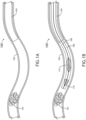
- FIGS. 1A through 1F illustrate one or more embodiments of an obstruction removal system 100.
- the obstruction removal system 100 includes a guide catheter 104 (e.g., any suitable guide catheter, aspiration catheter, or any other suitable tube) configured to be inserted through a vasculature 102 to a position proximate to an obstruction 101.
- the obstruction removal system 100 further includes an obstruction removal device comprising a removal tool 110 and an expandable member 112 configured to be inserted through the guide catheter 104.
- the removal tool 110 and the expandable member 112 may be coupled or formed on/near a distal end of a delivery tool 108 that is configured to be inserted through the guide catheter 104.
- the delivery tool 108 may be a guide wire or tube.
- the removal tool 110 may be fixed to the distal end of the guide wire or tube, and the expandable member 112 may be fixed or slidably coupled to the guide wire or tube at a position near the removal tool 110.
- the obstruction removal device i.e., the removal tool 110 and the expandable member 112 on the delivery tool 108 may be at least partially housed within an intermediate catheter 106 (e.g., any suitable intermediate catheter, microcatheter, or any other suitable tube) during insertion.
- the intermediate catheter 106 may be used to contain and keep the removal tool 110 and the expandable member 112 from expanding within the guide catheter 104. This may provide one or more advantages, such as, but not limited to, reducing friction between the removal tool 110/expandable member 112 and the guide catheter 104, permitting the removal tool 110 and the expandable member 112 to be inserted through the distal opening of the guide catheter 104, and preventing the removal tool 110/expandable member 112 from prematurely engaging the obstruction 101.
- FIG. 1B illustrates the obstruction removal device deployed within the vasculature 102 in proximity to an obstruction 101.
- the delivery tool 108 e.g., a guide wire and/or tube
- the delivery tool 108 is configured to be inserted within the guide catheter 104 and disposed proximate to the obstruction 101 in the vasculature 102.
- the delivery tool 108 carrying the end-mounted the removal tool 110 and the expandable member 112, may be fed through the guide catheter 104 using the intermediate catheter 106 to contain/sheathe the removal tool 110 and the expandable member 112 during their insertion.
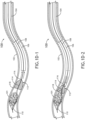
- the intermediate catheter 106 may be configured to unsheathe the removal tool 110 and the expandable member 112 so that the removal tool 110 can engage the obstruction 101 in the vasculature 102. For example, after reaching a desired position within the vasculature 102, the intermediate catheter 106 may be pulled back (and/or the delivery tool 108 may be pushed forward relative to the intermediate catheter 106) to unsheathe the removal tool 110 and the expandable member 112 so that the removal tool 110 can engage the obstruction 101.
- the removal tool 110 is configured to at least partially separate the obstruction 101 from the inner surface of the vasculature 102 (e.g., from the vessel wall).
- the removal tool 110 comprises a conical or umbrella-shaped section (e.g., a conical and/or umbrella shaped net-like structure or mesh) configured to at least partially surround the obstruction 101.
- the removal tool 110 comprises a differently shaped net-like structure or mesh configured to at least partially surround the obstruction 101 (e.g., a semi-circular or cylindrical structure, or the like).
- the distal end of the removal tool 110 may be attached to the guide wire and another (mid) portion of the removal tool may be attached to the tube so that moving the guide wire independent of (e.g., relative to) the tube causes the removal tool 110 to expand or collapse, much like an umbrella.
- the removal tool 110 may be formed from a shape memory and/or super elastic alloy (e.g., Nitinol) so that the removal tool 110 automatically expands when it is unsheathed. For example, the removal tool 110 may be guided past the obstruction 101, unsheathed, and then pulled back to scrape/scoop the obstruction 101 off the inner surface of the vasculature 102.
- the expandable member 112 includes a distal end 114 that is fixedly or slidably coupled to the delivery tool 110 and a proximal end 116 that is slidably coupled to the delivery tool 110.
- the expandable member 112 may be positioned so that, during its deployment, the distal end 114 is located in between the removal tool 110 and the proximal end 116.
- the proximal end 116 of the expandable member 112 may be configured to slide toward the distal end 114 of the expandable member 112, thereby causing the expandable member 112 to surround at least a portion of the obstruction 101 and the removal tool 110 so that the obstruction 101 is captured between the expandable member 112 and the removal tool 110.
- a middle portion 118 of the expandable member 112 is configured to fold over the distal end 114 of the expandable member 112 and at least a portion of the removal tool 110, so that the obstruction 101 is captured between the expandable member 112 and the removal tool 110.
- the guide catheter 104, or the intermediate catheter 106 may cause the middle portion of the expandable member 112 to fold over the removal tool 110 so that the obstruction 101 is captured between the expandable member 112 and the removal tool 110.
- the resistance from fluid in the vasculature 102 may cause the middle portion of the expandable member 112 to fold over the removal tool 110 so that the obstruction 101 is captured between the expandable member 112 and the removal tool 110.
- the intermediate catheter 106 (or guide catheter 104) may be used to urge the expandable member 112 to invert and/or fold over itself.
- FIG. 1E illustrates the obstruction 101 captured between the expandable member 112 and the removal tool 110, as the delivery tool 108 is being withdrawn from the vasculature 102 to remove the removal tool 110 and the obstruction 101 from the vasculature 102.
- the delivery tool 108 may be pulled back into the guide catheter 104 and/or intermediate catheter 106 to remove the obstruction 101 that is captured between the expandable member 112 and the removal tool 110 from the vasculature 102.
- the intermediate catheter 106 with the delivery tool 108 and the obstruction 101 that is captured between the expandable member 112 and the removal tool 110 may be pulled back through the guide catheter 104 to remove the obstruction 101 from the vasculature 102.
- the delivery tool 108 with the obstruction removal device (including removal tool 110 and expandable member 112) and the obstruction 101 may be withdrawn through the intermediate catheter 106, as depicted in FIG. 1F .
- the delivery tool 108 with the obstruction 101 that is captured between the expandable member 112 and the removal tool 110 may be pulled directly through the guide catheter 104 (without use of an intermediate catheter 106).
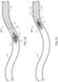
- FIGS. 2A through 2F illustrate another embodiment of the obstruction removal system 100, wherein the expandable member 112 has a distal end 114 coupled to the delivery tool 108 and a proximal end 116 that is configured to move freely.
- the expandable member 112 may comprise a conical/umbrella-shaped net or mesh structure with one end fixedly or slidably coupled to the delivery tool 108 and one free/open end.
- the expandable member 112 may be oriented so that the proximal end 116 of the expandable member 112 is facing away from the removal tool 110. Then, as shown in FIG.
- the proximal end 116 of the expandable member 112 may be configured to invert toward the distal end 114 of the expandable member 112, thereby causing the expandable member 112 to surround at least a portion of the obstruction 101 and the removal tool 110 so that the obstruction 101 is captured between the expandable member 112 and the removal tool 110.
- the proximal end 116 of the expandable member 112 is configured to invert and drape over the distal end 114 of the expandable member 112 and at least a portion of the removal tool 110 as the delivery tool 108 is withdrawn from the vasculature 102 to remove the removal tool 110 and the obstruction 101 from the vasculature 102.
- the delivery tool 108 when the delivery tool 108 is pulled back through the guide catheter 104 and/or intermediate catheter 106, the resulting friction between the proximal (i.e., free) end 116 of the expandable member 112 and the inner surface of the vasculature 102, the guide catheter 104, or the intermediate catheter 106 may cause the expandable member 112 to invert and drape over the removal tool 110 so that the obstruction 101 is captured between the expandable member 112 and the removal tool 110.
- the proximal (i.e., free) end 116 of the expandable member 112 and the inner surface of the vasculature 102, the guide catheter 104, or the intermediate catheter 106 may cause the expandable member 112 to invert and drape over the removal tool 110 so that the obstruction 101 is captured between the expandable member 112 and the removal tool 110.
- the resistance from fluid in the vasculature 102 may cause the expandable member 112 to invert and drape over the removal tool 110 so that the obstruction 101 is captured between the expandable member 112 and the removal tool 110.
- FIG. 2E illustrates the obstruction 101 captured between the expandable member 112 and the removal tool 110, as the delivery tool 108 is being withdrawn from the vasculature 102 to remove the removal tool 110 and the obstruction 101 from the vasculature 102.
- the delivery tool 108 may be pulled back into the guide catheter 104 and/or intermediate catheter 106 to remove the obstruction 101 that is captured between the expandable member 112 and the removal tool 110 from the vasculature 102.
- the intermediate catheter 106 with the delivery tool 108 and the obstruction 101 that is captured between the expandable member 112 and the removal tool 110 may be pulled back through the guide catheter 104 to remove the obstruction 101 from the vasculature 102.
- the delivery tool 108 with the obstruction removal device (including removal tool 110 and expandable member 112) and the obstruction 101 may be withdrawn through the intermediate catheter 106, as depicted in FIG. 2F .
- the delivery tool 108 with the obstruction 101 that is captured between the expandable member 112 and the removal tool 110 may be pulled directly through the guide catheter 104 (without use of an intermediate catheter 106).
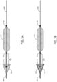
- FIGS. 3A through 5C various embodiments of the removal tool 110 are shown and described.
- Embodiments of the removal tool 110 illustrated in FIGS. 3A through 5C may be employed with any embodiments of the obstruction removal system 100 illustrated in FIGS. 1A through 2F or otherwise described herein.
- the obstruction removal device may include a passive removal tool 110.
- the removal tool 110 may be configured to expand upon deployment (e.g., unsheathing) from the intermediate catheter 106.
- the removal tool 110 may include a distal end 109 (e.g., tip coil) that is fixed to a distal end of the delivery tool 108 (e.g., delivery tube or wire) and a proximal end 111 that is fixed or slidably coupled to another portion of the delivery tool 108 such that an obstruction landing area 120 on the delivery tool 108 is defined between the proximal end 111 of the removal tool 110 and the distal end 114 of the expandable member 112.
- the ends of the removal tool 110 and/or expandable member 112 comprise marker bands that are coupled to the delivery tool 108.
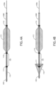
- FIGS. 4A through 4C illustrate embodiments of the obstruction removal device including an active removal tool 110.
- the removal tool 110 may be selectively expanded or collapsed.
- the removal tool 110 may be expanded or collapsed by actuating two portions of a delivery tool 108 (e.g., a delivery wire 108A and a delivery tube 108B) relative to one another.
- a delivery tool 108 e.g., a delivery wire 108A and a delivery tube 108B
- the removal tool 110 may include a distal end 109 (e.g., tip coil) that is fixed to a distal end of the delivery wire 108A and a proximal end 111 that is fixed to a distal end of the delivery tube 108B, either directly or via an obstruction landing area 120 between the proximal end 111 of the removal tool 110 and the distal end 114 of the expandable member 112 (as shown).
- a distal end 109 e.g., tip coil
- the expandable member 112 may be coupled to the delivery tube 108B such that the obstruction landing area 120 is defined between the proximal end 111 of the removal tool 110 and the distal end 114 of the expandable member 112.
- the obstruction landing area 120 may comprise a wire mesh portion that connects the removal tool 110 and the expandable member 112 together.
- the expandable member 112 and the removal tool 110 are portions of a continuous wire mesh structure.
- the ends of the removal tool 110 and/or expandable member 112 comprise marker bands that are coupled to respective portions of the delivery wire 108A and tube 108B.
- the removal tool 110 may be collapsed by pushing the delivery wire 108A through the delivery tube 108B (or pulling the delivery tube 108B away from the distal end of the delivery wire 108A) and may expanded by pulling the delivery wire 108A through the delivery tube 108B (or pushing the delivery tube 108B toward the distal end of the delivery wire 108A).
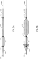
- FIGS. 5A through 5C illustrate embodiments of the obstruction removal device including an active removal tool 110 and an active expandable member 112.
- the removal tool 110 and the expandable member 112 may be selectively expanded or collapsed.
- the removal tool 110 may be expanded or collapsed by actuating two portions of a delivery tool 108 (e.g., a delivery wire 108A and a delivery tube 108B) relative to one another.
- a delivery tool 108 e.g., a delivery wire 108A and a delivery tube 108B
- the removal tool 110 may include a distal end 109 (e.g., tip coil) that is fixed to a distal end of the delivery wire 108A and a proximal end 111 that is connected to the distal end 114 of the expandable member 112 via an obstruction landing area 120 between the proximal end 111 of the removal tool 110 and the distal end 114 of the expandable member 112.
- the obstruction landing area 120 may comprise a wire mesh portion that connects the removal tool 110 and the expandable member 112 together.
- the expandable member 112 and the removal tool 110 are portions of a continuous wire mesh structure.
- the ends of the removal tool 110 and/or expandable member 112 comprise marker bands that are coupled to respective portions of the delivery wire 108A and tube 108B.
- the proximal end 116 of the expandable member 112 may be coupled to a distal end of the delivery tube 108B so that pulling the delivery tube 108B back relative to the delivery wire 108A (or extending the delivery wire 108A forward relative to the delivery tube 108B) causes the removal tool 110 and the expandable member 112 to collapse; and conversely, pulling the delivery wire 108A back relative to the delivery tube 108B (or pushing the delivery tube 108B forward relative to the delivery wire 108A) causes the removal tool 110 and the expandable member 112 to expand.
- the removal tool 110 may include a support frame 122 (e.g., one or more rigid or semi-rigid structures) that provide structural reinforcement for the removal tool 110 when the removal tool 110 is in a deployed (i.e., expanded) configuration.
- the support frame 122 may be configured to collapse (e.g., fold toward the delivery tool 108) when the removal tool 110 is in a collapsed configuration.
- the removal tool 110 may include non-uniform wire mesh.
- the removal tool 110 structure may comprise thicker, stronger, and/or denser wire mesh toward the distal end 109 of the removal tool 110 to provide a stronger conical/funnel shaped structure when the removal tool 110 is deployed/expanded and thinner, weaker, and/or less dense wire mesh toward the proximal end 111 of the removal tool 110 to provide flexibility for the removal tool 110 to expand/collapse more easily.
- the expandable member 112 may be configured to transition between contracted/collapsed and expanded states.
- the expandable member 112 may be configured to transition between the contracted and expanded states in any suitable way, including, but not limited to, unsheathing the expandable member 112 to allow expansion and sheathing/re-sheathing the expandable member 112 to induce contraction.
- the expanded state may allow the expandable member 112 to surround at least a portion of the removal tool 110 and/or the obstruction 101.
- the contracted state may be suitable for insertion and removal of the obstruction removal device (including expandable member 112 and removal tool 110) through the guide catheter 104 and/or intermediate catheter 106.
- the expandable member 112 and the removal tool 110 may be withdrawn through the guide catheter 104 and/or the intermediate catheter 106 to remove the obstruction 101 from the vasculature 102.
- Benefits of surrounding at least a portion of the removal tool 110 and/or the obstruction 101 with the expandable member 112 may include, but are not limited to, smaller cross-sectional area, reduced friction on a vessel wall, reduced likelihood of catching on an opening of the guide catheter 104 and/or intermediate catheter 106, and reduced likelihood of obstruction dislodgement.
- the expandable member 112 may be configured to transition between a first configuration and a second configuration, or between a contracted state and an expanded state, in any number of ways, including, but not limited to, unsheathing (e.g., withdrawal of the intermediate catheter 106 or extension through the guide catheter 104), disengagement of locking members (e.g., wires, hooks, etc.) attached to the expandable member 112, use of shape memory alloys (e.g., Nitinol), or the like. It is envisioned that when the expandable member is in an expanded state, the expandable member may take up a substantial portion of the cross-section of the vasculature 102.
- unsheathing e.g., withdrawal of the intermediate catheter 106 or extension through the guide catheter 104
- locking members e.g., wires, hooks, etc.
- shape memory alloys e.g., Nitinol
- the expandable member 112, removal tool 110, and the obstruction 101 are withdrawn into the guide catheter 104 and removed from the vasculature 102. In some embodiments, the expandable member 112, removal tool 110, and the obstruction 101 may be further withdrawn into the intermediate catheter 106.
- the expandable member 112 may surround at least a portion of the obstruction 101 to prevent dislodging and may also assist in compressing the obstruction 101 into the guide catheter 104 and/or the intermediate catheter 106 (e.g., by tension, cinching, crimping, etc.).
- Surrounding at least a portion of the removal tool 110 and/or obstruction 101 with the expandable member 112 may serve several functions including, but not limited to, reducing a likelihood that the removal tool 110 snags (e.g. on an inner surface/vessel wall of the vasculature 102 or an opening of the guide catheter 104), reducing a profile of the obstruction 101 for removal through the guide catheter 104 and/or intermediate catheter 106, and/or securing the obstruction 101 to prevent dislodgement from the removal tool 110.
- the removal tool 110 and/or expandable member 112 may comprise a wire mesh.
- a wire mesh may include wires made of a flexible material (e.g. nitinol, cobalt chromium, polymer mesh (e.g., PET or nylon), or the like), where the wires (e.g. 16 to 288 or more wires), have a certain diameter (e.g. from 0.0127 mm to 0.127 mm (.0005 inches to .0050 inches)), and have certain material properties (e.g. strength, coefficient of friction with blood, resistance to plastic deformation, etc.) suitable for engaging the obstruction 101 and/or removal tool 110.
- the wire mesh can be can be single ply or multiple plies.
- the wire mesh may include various sets of wires (e.g. support wires with larger diameters, wires to engage a vessel wall, wires to engage a portion of the obstruction or obstruction removal device, radiopaque or radiodense wires, etc.).
- any number of the presently disclosed elements may be suitable for imaging by a non-invasive imaging technology (e.g. X-ray, CT scans, etc.).
- the guide catheter 104, intermediate catheter 106, delivery tool 108, removal tool 110, expandable member 112, and/or any additional components may comprise radiodense or radiopaque material (e.g. titanium, tungsten, barium sulfate, zirconium oxide, Drawn Filled Tube (DFT), or the like) suitable for insertion in a human body.
- the removal tool 110 and the expandable member 112 are both portions of a common wire mesh structure formed from a radiodense or radiopaque material (e.g. DFT).
- any number of components of the obstruction removal system 100 may be attached by any suitable means including, but not limited to, welding, adhesive, mechanical fastening, interference fittings, etc.
- the delivery tool 108 may be attached to the removal tool 110 and/or expandable member 112 by such means.
- two or more of the components may be portions of a common structure (e.g., a common mold or print).
- Factors for determining an order may include, but are not limited to, vasculature properties (e.g. vasculature size, vasculature geometries, branches of the vasculature, vasculature wall strength, etc.), blood pressure, blood flow direction, duration of operation (i.e. does patient require a reduced operating time for safety concerns), size of obstruction, or the configuration of the obstruction removal device.
- vasculature properties e.g. vasculature size, vasculature geometries, branches of the vasculature, vasculature wall strength, etc.
- blood pressure e.g. blood pressure, blood flow direction, duration of operation (i.e. does patient require a reduced operating time for safety concerns), size of obstruction, or the configuration of the obstruction removal device.
- a method of removing an obstruction from a vasculature 102 may include, but is not limited to, the steps of: deploying the guide catheter 104 through the patient's vasculature 102 to a position near the obstruction 101; extending the delivery tool 108 with the end-mounted removal tool 110 through the guide catheter 104 so that the distal end of the delivery tool 108 is disposed proximate to the obstruction 101 in the vasculature 102 (with/without the use of the intermediate catheter 106); removing at least a portion of the obstruction 101 in the vasculature 102 by at least partially separating the obstruction 101 from an inner surface of the vasculature 102 with the removal tool 110; and surrounding at least a portion of the obstruction 101 and the removal tool 110 with the expandable member 112, wherein the proximal end 116 of the expandable member 112 is configured to invert or slide toward the distal end 114 of the expandable member 112, so that the obstruction 101 is captured
- implementations of the methods disclosed herein may include one or more of the steps described herein. Further, such steps may be carried out in any desired order and, in some implementations, two or more of the steps may be carried out simultaneously with one another. Two or more of the steps disclosed herein may be combined in a single step, and in some implementations., one or more of the steps may be carried out as two or more sub-steps. Further, other steps or sub-steps may be carried in addition to, or as substitutes to one or more of the steps disclosed herein.
- an "obstruction” may refer to any vascular obstruction, including but not limited to, a blood clot, plaque (e.g. fat, cholesterol, etc.), internal structure/growth, foreign object, or the like.
Landscapes
- Health & Medical Sciences (AREA)
- Surgery (AREA)
- Life Sciences & Earth Sciences (AREA)
- Heart & Thoracic Surgery (AREA)
- Nuclear Medicine, Radiotherapy & Molecular Imaging (AREA)
- Vascular Medicine (AREA)
- Engineering & Computer Science (AREA)
- Biomedical Technology (AREA)
- Orthopedic Medicine & Surgery (AREA)
- Medical Informatics (AREA)
- Molecular Biology (AREA)
- Animal Behavior & Ethology (AREA)
- General Health & Medical Sciences (AREA)
- Public Health (AREA)
- Veterinary Medicine (AREA)
- Surgical Instruments (AREA)
Claims (7)
- System zur Entfernung von Obstruktionen, umfassend:einen Führungskatheter (104), der konfiguriert ist, um in ein Gefäß (102) eingeführt zu werden;ein Abgabewerkzeug (108) mit einem distalen Ende, das konfiguriert ist, um in den Führungskatheter (104) eingeführt und nahe einer Obstruktion (101) in dem Gefäß (102) angeordnet zu werden; undeine durchgehende Drahtgeflechtstruktur (110, 112, 120), die an das Abgabewerkzeug (108) gekoppelt ist, wobei jeweilige Teile der durchgehenden Drahtgeflechtstruktur Folgendes bilden:ein Entfernungswerkzeug (110), das an dem distalen Ende des Abgabewerkzeugs (108) angeordnet und konfiguriert ist, um die Obstruktion (101) zumindest teilweise von einer Innenfläche des Gefäßes (102) zu trennen, wobei das Entfernungswerkzeug (110) einen konischen oder schirmförmigen Abschnitt umfasst, der konfiguriert ist, um die Obstruktion zumindest teilweise zu umgeben;ein erweiterbares Element (112), das an das Abgabewerkzeug (108) gekoppelt ist, wobei das erweiterbare Element (112) ein proximales Ende (116) beinhaltet, das verschiebbar an das Abgabewerkzeug (108) gekoppelt ist, wobei das proximale Ende (116) des erweiterbaren Elements (112) konfiguriert ist, um zu invertieren oder sich zu einem distalen Ende (114) des erweiterbaren Elements (112) zu verschieben, wodurch bewirkt wird, dass das erweiterbare Element (112) zumindest einen Teil der Obstruktion (101) und des Entfernungswerkzeugs (110) umgibt, sodass die Obstruktion (101) zwischen dem erweiterbaren Element (112) und dem Entfernungswerkzeug (110) gefangen ist, wenn das Abgabewerkzeug (108) aus dem Gefäß (102) zurückgezogen wird, um das Entfernungswerkzeug (110) und die Obstruktion (101) aus dem Gefäß (102) zu entfernen; undeinen Obstruktionslandebereich (120) zwischen dem Entfernungswerkzeug (110) und dem erweiterbaren Element (112), wobei die Enden des Entfernungswerkzeugs (110) und des erweiterbaren Elements (112) Markierungsbänder umfassen, die an das Abgabewerkzeug (108) gekoppelt sind.
- System zur Entfernung von Obstruktionen nach Anspruch 1, wobei das distale Ende des erweiterbaren Elements fest oder verschiebbar an das Abgabewerkzeug gekoppelt ist.
- System zur Entfernung von Obstruktionen nach Anspruch 1, wobei das proximale Ende des erweiterbaren Elements verschiebbar an das Abgabewerkzeug gekoppelt ist und konfiguriert ist, um sich zu dem distalen Ende des erweiterbaren Elements zu verschieben, wenn das Abgabewerkzeug aus dem Gefäß zurückgezogen wird, um das Entfernungswerkzeug und die Obstruktion aus dem Gefäß zu entfernen, und wobei ein mittlerer Teil des erweiterbaren Elements konfiguriert ist, um sich über das distale Ende des erweiterbaren Elements und zumindest einen Teil des Entfernungswerkzeugs zu falten, sodass die Obstruktion zwischen dem erweiterbaren Element und dem Entfernungswerkzeug gefangen ist, wenn sich das proximale Ende des erweiterbaren Elements zu dem distalen Ende des erweiterbaren Elements verschiebt, während das Abgabewerkzeug aus dem Gefäß zurückgezogen wird, um das Entfernungswerkzeug und die Obstruktion aus dem Gefäß zu entfernen.
- System zur Entfernung von Obstruktionen nach Anspruch 1, wobei das proximale Ende des erweiterbaren Elements frei ist und konfiguriert ist, um zu invertieren und sich über das distale Ende des erweiterbaren Elements und zumindest einen Teil des Entfernungswerkzeugs zu stülpen, sodass die Obstruktion zwischen dem erweiterbaren Element und dem Entfernungswerkzeug gefangen ist, wenn das Abgabewerkzeug aus dem Gefäß zurückgezogen wird, um das Entfernungswerkzeug und die Obstruktion aus dem Gefäß zu entfernen.
- System zur Entfernung von Obstruktionen nach Anspruch 1, ferner umfassend:
einen Zwischenkatheter, der konfiguriert ist, um das Entfernungswerkzeug und das erweiterbare Element zu umhüllen, während das Abgabewerkzeug in den Führungskatheter eingeführt und in das Gefäß geführt wird. - System zur Entfernung von Obstruktionen nach Anspruch 5, wobei der Zwischenkatheter ferner konfiguriert ist, um das Entfernungswerkzeug und das erweiterbare Element zu enthüllen, um dem Entfernungswerkzeug zu ermöglichen, die Obstruktion zumindest teilweise von der Innenfläche des Gefäßes zu trennen.
- System zur Entfernung von Obstruktionen nach Anspruch 1, wobei das Abgabewerkzeug zumindest eines von einem Führungsdraht oder einer Röhre umfasst.
Applications Claiming Priority (2)
| Application Number | Priority Date | Filing Date | Title |
|---|---|---|---|
| US201962789584P | 2019-01-08 | 2019-01-08 | |
| PCT/US2020/012528 WO2020146343A1 (en) | 2019-01-08 | 2020-01-07 | Apparatus, system, and method for vasculature obstruction removal |
Publications (4)
| Publication Number | Publication Date |
|---|---|
| EP3908211A1 EP3908211A1 (de) | 2021-11-17 |
| EP3908211A4 EP3908211A4 (de) | 2022-08-31 |
| EP3908211B1 true EP3908211B1 (de) | 2024-10-09 |
| EP3908211C0 EP3908211C0 (de) | 2024-10-09 |
Family
ID=71403987
Family Applications (1)
| Application Number | Title | Priority Date | Filing Date |
|---|---|---|---|
| EP20738354.8A Active EP3908211B1 (de) | 2019-01-08 | 2020-01-07 | System zur entfernung von gefässobstruktionen |
Country Status (6)
| Country | Link |
|---|---|
| US (2) | US11284913B2 (de) |
| EP (1) | EP3908211B1 (de) |
| JP (1) | JP7636329B2 (de) |
| CN (1) | CN113543732A (de) |
| ES (1) | ES2997683T3 (de) |
| WO (1) | WO2020146343A1 (de) |
Families Citing this family (2)
| Publication number | Priority date | Publication date | Assignee | Title |
|---|---|---|---|---|
| US11172946B2 (en) * | 2018-10-26 | 2021-11-16 | Progressive NEURO, Inc. | Apparatus, system, and method for vasculature obstruction removal |
| US20230062684A1 (en) * | 2021-08-28 | 2023-03-02 | Sheri Albers | Intravascular thrombectomy device and process for treating acute ischemic stroke |
Family Cites Families (73)
| Publication number | Priority date | Publication date | Assignee | Title |
|---|---|---|---|---|
| US4926858A (en) | 1984-05-30 | 1990-05-22 | Devices For Vascular Intervention, Inc. | Atherectomy device for severe occlusions |
| US4886061A (en) | 1988-02-09 | 1989-12-12 | Medinnovations, Inc. | Expandable pullback atherectomy catheter system |
| EP1695673A3 (de) * | 1994-07-08 | 2009-07-08 | ev3 Inc. | Intravaskulärer Filter |
| US5895398A (en) | 1996-02-02 | 1999-04-20 | The Regents Of The University Of California | Method of using a clot capture coil |
| US5935139A (en) * | 1996-05-03 | 1999-08-10 | Boston Scientific Corporation | System for immobilizing or manipulating an object in a tract |
| US5662671A (en) | 1996-07-17 | 1997-09-02 | Embol-X, Inc. | Atherectomy device having trapping and excising means for removal of plaque from the aorta and other arteries |
| US6210370B1 (en) | 1997-01-10 | 2001-04-03 | Applied Medical Resources Corporation | Access device with expandable containment member |
| US6508825B1 (en) | 1997-02-28 | 2003-01-21 | Lumend, Inc. | Apparatus for treating vascular occlusions |
| US5814064A (en) * | 1997-03-06 | 1998-09-29 | Scimed Life Systems, Inc. | Distal protection device |
| WO1998039053A1 (en) * | 1997-03-06 | 1998-09-11 | Scimed Life Systems, Inc. | Distal protection device and method |
| US5772674A (en) | 1997-03-31 | 1998-06-30 | Nakhjavan; Fred K. | Catheter for removal of clots in blood vessels |
| DE19811364C2 (de) | 1998-03-16 | 2000-01-27 | Gerhard Benker | Ballondilatationskatheter mit antithrombotischem Filtersieb und Ballondilatationskatheter in einem Resektionsinstrument befestigt |
| US6511492B1 (en) | 1998-05-01 | 2003-01-28 | Microvention, Inc. | Embolectomy catheters and methods for treating stroke and other small vessel thromboembolic disorders |
| US6342062B1 (en) | 1998-09-24 | 2002-01-29 | Scimed Life Systems, Inc. | Retrieval devices for vena cava filter |
| US6458139B1 (en) | 1999-06-21 | 2002-10-01 | Endovascular Technologies, Inc. | Filter/emboli extractor for use in variable sized blood vessels |
| AU2749801A (en) | 1999-11-16 | 2001-05-30 | Deka Products Limited Partnership | Endarterectomy surgical instrument |
| US6663613B1 (en) | 2000-01-25 | 2003-12-16 | Bacchus Vascular, Inc. | System and methods for clot dissolution |
| US8298257B2 (en) * | 2000-06-29 | 2012-10-30 | Concentric Medical, Inc. | Systems, methods and devices for removing obstructions from a blood vessel |
| US20030176884A1 (en) * | 2002-03-12 | 2003-09-18 | Marwane Berrada | Everted filter device |
| WO2005094283A2 (en) | 2004-03-25 | 2005-10-13 | Hauser David L | Vascular filter device |
| US8252017B2 (en) * | 2005-10-18 | 2012-08-28 | Cook Medical Technologies Llc | Invertible filter for embolic protection |
| DE102005059670A1 (de) | 2005-12-12 | 2007-06-14 | Phenox Gmbh | Vorrichtung zur Entfernung von Thromben aus Blutgefässen |
| CA2633866A1 (en) | 2005-12-30 | 2007-07-12 | C.R. Bard Inc. | Embolus blood clot filter removal system and method |
| DE102006044831A1 (de) | 2006-09-20 | 2008-04-03 | Phenox Gmbh | Vorrichtung zur Entfernung von Thromben aus Blutgefäßen |
| US9149609B2 (en) | 2006-10-16 | 2015-10-06 | Embolitech, Llc | Catheter for removal of an organized embolic thrombus |
| WO2009086482A1 (en) | 2007-12-26 | 2009-07-09 | Lazarus Effect, Inc. | Retrieval systems and methods for use thereof |
| WO2010010545A1 (en) | 2008-07-22 | 2010-01-28 | Neuravi Limited | Clot capture systems and associated methods |
| EP2344051B1 (de) | 2008-09-22 | 2016-11-09 | Hotspur Technologies, Inc | Flusswiederherstellungssysteme |
| US20100131000A1 (en) | 2008-11-21 | 2010-05-27 | Radius Medical Technologies, Inc. | System and method for removal of material from a blood vessel |
| EP2403583B1 (de) | 2009-03-06 | 2016-10-19 | Lazarus Effect, Inc. | Abfragesysteme |
| US20100249815A1 (en) | 2009-03-25 | 2010-09-30 | Cook Incorporated | Everted sheath thrombectomy device |
| CH701695A1 (de) | 2009-08-27 | 2011-02-28 | Straub Medical Ag | Katheter mit Protektionssystem zum Ansaugen, Fragmentieren und Hinausfördern von entfernbarem Material aus Hohlkörpern bzw. Gefässen, insbesondere des menschlichen oder tierischen Körpers. |
| WO2011091383A1 (en) | 2010-01-22 | 2011-07-28 | Lazarus Effect, Inc. | Retrieval systems and methods for use thereof |
| US9211396B2 (en) * | 2010-02-23 | 2015-12-15 | Covidien Lp | Devices and methods for vascular recanalization |
| GB2478592B (en) | 2010-03-12 | 2012-02-29 | Cook Medical Technologies Llc | Obstruction removal assembly and method |
| WO2012009675A2 (en) | 2010-07-15 | 2012-01-19 | Lazarus Effect, Inc. | Retrieval systems and methods for use thereof |
| US10039900B2 (en) | 2010-09-07 | 2018-08-07 | Angiodynamics, Inc. | Fluid delivery and treatment device and method of use |
| JP6087281B2 (ja) * | 2010-09-10 | 2017-03-01 | メディナ メディカル,インコーポレイテッド | 血管異常を治療するデバイス及び方法 |
| EP3398539B1 (de) | 2011-05-23 | 2020-08-26 | Covidien LP | Abfragesysteme |
| US11026708B2 (en) | 2011-07-26 | 2021-06-08 | Thrombx Medical, Inc. | Intravascular thromboembolectomy device and method using the same |
| EP3485824A3 (de) | 2011-10-04 | 2019-08-07 | Angioworks Medical B.V. | Vorrichtungen zur perkutanen arterieninnenhautentfernung |
| WO2013166049A1 (en) | 2012-04-30 | 2013-11-07 | BiO2 Medical, Inc. | Multi-lumen central access vena cava filter apparatus for clot management and method of using same |
| US9358022B2 (en) | 2012-05-21 | 2016-06-07 | Noha, Llc | Clot removal device and method of using same |
| ES2647893T3 (es) | 2012-06-26 | 2017-12-27 | V.V.T. Med Ltd. | Dispositivos de oclusión vascular |
| US9597171B2 (en) | 2012-09-11 | 2017-03-21 | Covidien Lp | Retrieval catheter with expandable tip |
| US11419620B2 (en) | 2012-10-03 | 2022-08-23 | The University Of Toledo | Minimally invasive thrombectomy |
| WO2014055609A1 (en) | 2012-10-03 | 2014-04-10 | The University Of Toledo | Minimally invasive thrombectomy invention |
| US20140276403A1 (en) * | 2013-03-13 | 2014-09-18 | DePuy Synthes Products, LLC | Ischemic stroke device |
| US9833252B2 (en) | 2013-03-15 | 2017-12-05 | Microvention, Inc. | Multi-component obstruction removal system and method |
| US10231751B2 (en) | 2013-05-29 | 2019-03-19 | Thomas A. Sos | Thrombus removal and intravascular distal embolic protection device |
| US10383644B2 (en) | 2013-10-17 | 2019-08-20 | Covidien Lp | Mechanical thrombectomy with proximal occlusion |
| JP6352642B2 (ja) | 2013-12-03 | 2018-07-04 | 川澄化学工業株式会社 | 血管内異物除去用カテーテル |
| US10271863B2 (en) | 2014-03-04 | 2019-04-30 | Thrombx Medical, Inc. | Intravascular thromboembolectomy device comprising a plurality of clot engaging elements and method using the same |
| US11253278B2 (en) | 2014-11-26 | 2022-02-22 | Neuravi Limited | Clot retrieval system for removing occlusive clot from a blood vessel |
| US9987028B2 (en) | 2015-02-12 | 2018-06-05 | Cook Medical Technologies Llc | Partially covered braided funnel aspiration catheter |
| WO2016186939A1 (en) * | 2015-05-15 | 2016-11-24 | Teleflex Medical Incorporated | Tethered filter assemblies and methods for use thereof |
| CN113116459B (zh) | 2015-08-06 | 2025-01-10 | 瓦斯科尔勒治疗股份有限公司 | 轴向伸长的血栓捕获系统 |
| CN108348319B (zh) | 2015-09-28 | 2020-03-10 | 斯瑞克公司 | 机械取栓装置和方法 |
| AU2016344440B2 (en) | 2015-10-31 | 2020-11-05 | Neurovasc Technologies, Inc. | Embolus removal device with blood flow restriction and related methods |
| CN109414272B (zh) * | 2016-04-25 | 2021-09-28 | 斯瑞克公司 | 翻转机械血栓切除装置及在血管系统中使用的方法 |
| EP3505091B1 (de) | 2016-08-29 | 2022-09-21 | Terumo Kabushiki Kaisha | Medizinische vorrichtung |
| JP2019187457A (ja) | 2016-08-29 | 2019-10-31 | テルモ株式会社 | 吸引システムおよび処置方法 |
| JP2019187458A (ja) | 2016-08-29 | 2019-10-31 | テルモ株式会社 | 吸引カテーテルおよび吸引システム並びに処置方法 |
| WO2018118706A1 (en) | 2016-12-20 | 2018-06-28 | Lattouf Omar M | Clot retrievers and methods for deployment |
| US11141178B2 (en) | 2017-03-03 | 2021-10-12 | Maria G. Aboytes | Systems, devices, and methods for obstruction retrieval and treatment |
| US10575864B2 (en) | 2017-06-22 | 2020-03-03 | Covidien Lp | Securing element for resheathing an intravascular device and associated systems and methods |
| JP6977341B2 (ja) | 2017-07-06 | 2021-12-08 | 富士フイルムビジネスイノベーション株式会社 | 情報処理システム、情報処理装置及びプログラム |
| JP2020533153A (ja) | 2017-09-11 | 2020-11-19 | スロンムエックス メディカル インコーポレイテッドThrombx Medical Inc. | 血管内血栓塞栓除去デバイスおよび方法 |
| US20190239905A1 (en) | 2018-02-08 | 2019-08-08 | Nexgen Medical Systems, Inc. | Retraction device, system, and method |
| WO2019178165A1 (en) | 2018-03-12 | 2019-09-19 | Xtract Medical | Devices and methods for removing material from a patient |
| JP7522105B2 (ja) * | 2018-05-30 | 2024-07-24 | イーラム テクノロジーズ,インコーポレイテッド | 統合血栓除去術及びフィルタデバイス並びに使用方法 |
| US10898216B2 (en) * | 2018-06-13 | 2021-01-26 | DePuy Synthes Products, Inc. | Vasculature obstruction capture device |
| CN109199533A (zh) | 2018-11-01 | 2019-01-15 | 郑州大学第附属医院 | 一种螺旋封堵式血栓取出装置 |
-
2020
- 2020-01-07 JP JP2021539875A patent/JP7636329B2/ja active Active
- 2020-01-07 ES ES20738354T patent/ES2997683T3/es active Active
- 2020-01-07 US US16/736,279 patent/US11284913B2/en active Active
- 2020-01-07 EP EP20738354.8A patent/EP3908211B1/de active Active
- 2020-01-07 WO PCT/US2020/012528 patent/WO2020146343A1/en not_active Ceased
- 2020-01-07 CN CN202080018659.3A patent/CN113543732A/zh active Pending
-
2022
- 2022-03-21 US US17/699,906 patent/US11857211B2/en active Active
Also Published As
| Publication number | Publication date |
|---|---|
| EP3908211A4 (de) | 2022-08-31 |
| EP3908211A1 (de) | 2021-11-17 |
| CN113543732A (zh) | 2021-10-22 |
| JP7636329B2 (ja) | 2025-02-26 |
| US20200214728A1 (en) | 2020-07-09 |
| JP2022516963A (ja) | 2022-03-03 |
| US11857211B2 (en) | 2024-01-02 |
| ES2997683T3 (en) | 2025-02-17 |
| EP3908211C0 (de) | 2024-10-09 |
| US20220265293A1 (en) | 2022-08-25 |
| US11284913B2 (en) | 2022-03-29 |
| WO2020146343A1 (en) | 2020-07-16 |
Similar Documents
| Publication | Publication Date | Title |
|---|---|---|
| US10722257B2 (en) | Retrieval of material from vessel lumens | |
| US11622781B2 (en) | Apparatus and method for neurovascular endoluminal intervention | |
| US11723678B2 (en) | Apparatus, system, and method for vasculature obstruction removal | |
| US20220233208A1 (en) | Apparatus, system, and method for vasculature obstruction removal | |
| JP2013071002A (ja) | 管装置のための遠位脱離機構 | |
| US11129630B2 (en) | Retrieval of material from vessel lumens | |
| US11684379B2 (en) | Retrieval of material from vessel lumens | |
| US11857211B2 (en) | Apparatus, system, and method for vasculature obstruction removal | |
| US11191555B2 (en) | Retrieval of material from vessel lumens | |
| US11298145B2 (en) | Retrieval of material from vessel lumens | |
| US11172946B2 (en) | Apparatus, system, and method for vasculature obstruction removal | |
| EP3621533B1 (de) | Gerät für rückholung von material aus gefässlumen | |
| WO2024138010A2 (en) | Embolic protection system | |
| WO2022159699A1 (en) | Apparatus, system, method for vasculature obstruction removal |
Legal Events
| Date | Code | Title | Description |
|---|---|---|---|
| STAA | Information on the status of an ep patent application or granted ep patent |
Free format text: STATUS: THE INTERNATIONAL PUBLICATION HAS BEEN MADE |
|
| PUAI | Public reference made under article 153(3) epc to a published international application that has entered the european phase |
Free format text: ORIGINAL CODE: 0009012 |
|
| STAA | Information on the status of an ep patent application or granted ep patent |
Free format text: STATUS: REQUEST FOR EXAMINATION WAS MADE |
|
| 17P | Request for examination filed |
Effective date: 20210803 |
|
| AK | Designated contracting states |
Kind code of ref document: A1 Designated state(s): AL AT BE BG CH CY CZ DE DK EE ES FI FR GB GR HR HU IE IS IT LI LT LU LV MC MK MT NL NO PL PT RO RS SE SI SK SM TR |
|
| DAV | Request for validation of the european patent (deleted) | ||
| DAX | Request for extension of the european patent (deleted) | ||
| REG | Reference to a national code |
Ref country code: DE Ref legal event code: R079 Free format text: PREVIOUS MAIN CLASS: A61B0017220000 Ipc: A61B0017221000 Ref country code: DE Ref legal event code: R079 Ref document number: 602020039077 Country of ref document: DE Free format text: PREVIOUS MAIN CLASS: A61B0017220000 Ipc: A61B0017221000 |
|
| A4 | Supplementary search report drawn up and despatched |
Effective date: 20220729 |
|
| RIC1 | Information provided on ipc code assigned before grant |
Ipc: A61B 17/22 20060101ALI20220725BHEP Ipc: A61B 17/221 20060101AFI20220725BHEP |
|
| GRAP | Despatch of communication of intention to grant a patent |
Free format text: ORIGINAL CODE: EPIDOSNIGR1 |
|
| STAA | Information on the status of an ep patent application or granted ep patent |
Free format text: STATUS: GRANT OF PATENT IS INTENDED |
|
| INTG | Intention to grant announced |
Effective date: 20240429 |
|
| RIN1 | Information on inventor provided before grant (corrected) |
Inventor name: FOLLMER, BRETT ALLEN |
|
| GRAS | Grant fee paid |
Free format text: ORIGINAL CODE: EPIDOSNIGR3 |
|
| GRAA | (expected) grant |
Free format text: ORIGINAL CODE: 0009210 |
|
| STAA | Information on the status of an ep patent application or granted ep patent |
Free format text: STATUS: THE PATENT HAS BEEN GRANTED |
|
| AK | Designated contracting states |
Kind code of ref document: B1 Designated state(s): AL AT BE BG CH CY CZ DE DK EE ES FI FR GB GR HR HU IE IS IT LI LT LU LV MC MK MT NL NO PL PT RO RS SE SI SK SM TR |
|
| REG | Reference to a national code |
Ref country code: CH Ref legal event code: EP |
|
| REG | Reference to a national code |
Ref country code: DE Ref legal event code: R096 Ref document number: 602020039077 Country of ref document: DE |
|
| REG | Reference to a national code |
Ref country code: IE Ref legal event code: FG4D |
|
| U01 | Request for unitary effect filed |
Effective date: 20241025 |
|
| U07 | Unitary effect registered |
Designated state(s): AT BE BG DE DK EE FI FR IT LT LU LV MT NL PT RO SE SI Effective date: 20241129 |
|
| REG | Reference to a national code |
Ref country code: ES Ref legal event code: FG2A Ref document number: 2997683 Country of ref document: ES Kind code of ref document: T3 Effective date: 20250217 |
|
| U20 | Renewal fee for the european patent with unitary effect paid |
Year of fee payment: 6 Effective date: 20250130 |
|
| PG25 | Lapsed in a contracting state [announced via postgrant information from national office to epo] |
Ref country code: IS Free format text: LAPSE BECAUSE OF FAILURE TO SUBMIT A TRANSLATION OF THE DESCRIPTION OR TO PAY THE FEE WITHIN THE PRESCRIBED TIME-LIMIT Effective date: 20250209 Ref country code: HR Free format text: LAPSE BECAUSE OF FAILURE TO SUBMIT A TRANSLATION OF THE DESCRIPTION OR TO PAY THE FEE WITHIN THE PRESCRIBED TIME-LIMIT Effective date: 20241009 |
|
| PG25 | Lapsed in a contracting state [announced via postgrant information from national office to epo] |
Ref country code: NO Free format text: LAPSE BECAUSE OF FAILURE TO SUBMIT A TRANSLATION OF THE DESCRIPTION OR TO PAY THE FEE WITHIN THE PRESCRIBED TIME-LIMIT Effective date: 20250109 |
|
| PG25 | Lapsed in a contracting state [announced via postgrant information from national office to epo] |
Ref country code: GR Free format text: LAPSE BECAUSE OF FAILURE TO SUBMIT A TRANSLATION OF THE DESCRIPTION OR TO PAY THE FEE WITHIN THE PRESCRIBED TIME-LIMIT Effective date: 20250110 |
|
| PG25 | Lapsed in a contracting state [announced via postgrant information from national office to epo] |
Ref country code: PL Free format text: LAPSE BECAUSE OF FAILURE TO SUBMIT A TRANSLATION OF THE DESCRIPTION OR TO PAY THE FEE WITHIN THE PRESCRIBED TIME-LIMIT Effective date: 20241009 |
|
| PG25 | Lapsed in a contracting state [announced via postgrant information from national office to epo] |
Ref country code: RS Free format text: LAPSE BECAUSE OF FAILURE TO SUBMIT A TRANSLATION OF THE DESCRIPTION OR TO PAY THE FEE WITHIN THE PRESCRIBED TIME-LIMIT Effective date: 20250109 |
|
| PG25 | Lapsed in a contracting state [announced via postgrant information from national office to epo] |
Ref country code: SM Free format text: LAPSE BECAUSE OF FAILURE TO SUBMIT A TRANSLATION OF THE DESCRIPTION OR TO PAY THE FEE WITHIN THE PRESCRIBED TIME-LIMIT Effective date: 20241009 |
|
| PG25 | Lapsed in a contracting state [announced via postgrant information from national office to epo] |
Ref country code: SK Free format text: LAPSE BECAUSE OF FAILURE TO SUBMIT A TRANSLATION OF THE DESCRIPTION OR TO PAY THE FEE WITHIN THE PRESCRIBED TIME-LIMIT Effective date: 20241009 |
|
| PG25 | Lapsed in a contracting state [announced via postgrant information from national office to epo] |
Ref country code: CZ Free format text: LAPSE BECAUSE OF FAILURE TO SUBMIT A TRANSLATION OF THE DESCRIPTION OR TO PAY THE FEE WITHIN THE PRESCRIBED TIME-LIMIT Effective date: 20241009 |
|
| PLBE | No opposition filed within time limit |
Free format text: ORIGINAL CODE: 0009261 |
|
| STAA | Information on the status of an ep patent application or granted ep patent |
Free format text: STATUS: NO OPPOSITION FILED WITHIN TIME LIMIT |
|
| REG | Reference to a national code |
Ref country code: CH Ref legal event code: PL |
|
| PG25 | Lapsed in a contracting state [announced via postgrant information from national office to epo] |
Ref country code: MC Free format text: LAPSE BECAUSE OF FAILURE TO SUBMIT A TRANSLATION OF THE DESCRIPTION OR TO PAY THE FEE WITHIN THE PRESCRIBED TIME-LIMIT Effective date: 20241009 |
|
| 26N | No opposition filed |
Effective date: 20250710 |
|
| PG25 | Lapsed in a contracting state [announced via postgrant information from national office to epo] |
Ref country code: CH Free format text: LAPSE BECAUSE OF NON-PAYMENT OF DUE FEES Effective date: 20250131 |
|
| PGFP | Annual fee paid to national office [announced via postgrant information from national office to epo] |
Ref country code: GB Payment date: 20251215 Year of fee payment: 7 |
|
| PGFP | Annual fee paid to national office [announced via postgrant information from national office to epo] |
Ref country code: IE Payment date: 20251218 Year of fee payment: 7 |
|
| U20 | Renewal fee for the european patent with unitary effect paid |
Year of fee payment: 7 Effective date: 20260128 |
|
| PGFP | Annual fee paid to national office [announced via postgrant information from national office to epo] |
Ref country code: ES Payment date: 20260202 Year of fee payment: 7 |