EP3904611A1 - Work machine - Google Patents
Work machine Download PDFInfo
- Publication number
- EP3904611A1 EP3904611A1 EP19906478.3A EP19906478A EP3904611A1 EP 3904611 A1 EP3904611 A1 EP 3904611A1 EP 19906478 A EP19906478 A EP 19906478A EP 3904611 A1 EP3904611 A1 EP 3904611A1
- Authority
- EP
- European Patent Office
- Prior art keywords
- cylinder
- working tool
- bucket
- detection
- piston rod
- Prior art date
- Legal status (The legal status is an assumption and is not a legal conclusion. Google has not performed a legal analysis and makes no representation as to the accuracy of the status listed.)
- Pending
Links
Images










Classifications
-
- E—FIXED CONSTRUCTIONS
- E02—HYDRAULIC ENGINEERING; FOUNDATIONS; SOIL SHIFTING
- E02F—DREDGING; SOIL-SHIFTING
- E02F3/00—Dredgers; Soil-shifting machines
- E02F3/04—Dredgers; Soil-shifting machines mechanically-driven
- E02F3/28—Dredgers; Soil-shifting machines mechanically-driven with digging tools mounted on a dipper- or bucket-arm, i.e. there is either one arm or a pair of arms, e.g. dippers, buckets
- E02F3/30—Dredgers; Soil-shifting machines mechanically-driven with digging tools mounted on a dipper- or bucket-arm, i.e. there is either one arm or a pair of arms, e.g. dippers, buckets with a dipper-arm pivoted on a cantilever beam, i.e. boom
- E02F3/32—Dredgers; Soil-shifting machines mechanically-driven with digging tools mounted on a dipper- or bucket-arm, i.e. there is either one arm or a pair of arms, e.g. dippers, buckets with a dipper-arm pivoted on a cantilever beam, i.e. boom working downwardly and towards the machine, e.g. with backhoes
- E02F3/325—Backhoes of the miniature type
-
- E—FIXED CONSTRUCTIONS
- E02—HYDRAULIC ENGINEERING; FOUNDATIONS; SOIL SHIFTING
- E02F—DREDGING; SOIL-SHIFTING
- E02F3/00—Dredgers; Soil-shifting machines
- E02F3/04—Dredgers; Soil-shifting machines mechanically-driven
- E02F3/96—Dredgers; Soil-shifting machines mechanically-driven with arrangements for alternate or simultaneous use of different digging elements
- E02F3/963—Arrangements on backhoes for alternate use of different tools
- E02F3/964—Arrangements on backhoes for alternate use of different tools of several tools mounted on one machine
-
- E—FIXED CONSTRUCTIONS
- E02—HYDRAULIC ENGINEERING; FOUNDATIONS; SOIL SHIFTING
- E02F—DREDGING; SOIL-SHIFTING
- E02F9/00—Component parts of dredgers or soil-shifting machines, not restricted to one of the kinds covered by groups E02F3/00 - E02F7/00
- E02F9/006—Pivot joint assemblies
-
- E—FIXED CONSTRUCTIONS
- E02—HYDRAULIC ENGINEERING; FOUNDATIONS; SOIL SHIFTING
- E02F—DREDGING; SOIL-SHIFTING
- E02F9/00—Component parts of dredgers or soil-shifting machines, not restricted to one of the kinds covered by groups E02F3/00 - E02F7/00
- E02F9/20—Drives; Control devices
- E02F9/22—Hydraulic or pneumatic drives
- E02F9/2264—Arrangements or adaptations of elements for hydraulic drives
- E02F9/2271—Actuators and supports therefor and protection therefor
-
- E—FIXED CONSTRUCTIONS
- E02—HYDRAULIC ENGINEERING; FOUNDATIONS; SOIL SHIFTING
- E02F—DREDGING; SOIL-SHIFTING
- E02F9/00—Component parts of dredgers or soil-shifting machines, not restricted to one of the kinds covered by groups E02F3/00 - E02F7/00
- E02F9/26—Indicating devices
- E02F9/264—Sensors and their calibration for indicating the position of the work tool
-
- F—MECHANICAL ENGINEERING; LIGHTING; HEATING; WEAPONS; BLASTING
- F15—FLUID-PRESSURE ACTUATORS; HYDRAULICS OR PNEUMATICS IN GENERAL
- F15B—SYSTEMS ACTING BY MEANS OF FLUIDS IN GENERAL; FLUID-PRESSURE ACTUATORS, e.g. SERVOMOTORS; DETAILS OF FLUID-PRESSURE SYSTEMS, NOT OTHERWISE PROVIDED FOR
- F15B15/00—Fluid-actuated devices for displacing a member from one position to another; Gearing associated therewith
- F15B15/08—Characterised by the construction of the motor unit
- F15B15/14—Characterised by the construction of the motor unit of the straight-cylinder type
- F15B15/16—Characterised by the construction of the motor unit of the straight-cylinder type of the telescopic type
-
- F—MECHANICAL ENGINEERING; LIGHTING; HEATING; WEAPONS; BLASTING
- F15—FLUID-PRESSURE ACTUATORS; HYDRAULICS OR PNEUMATICS IN GENERAL
- F15B—SYSTEMS ACTING BY MEANS OF FLUIDS IN GENERAL; FLUID-PRESSURE ACTUATORS, e.g. SERVOMOTORS; DETAILS OF FLUID-PRESSURE SYSTEMS, NOT OTHERWISE PROVIDED FOR
- F15B15/00—Fluid-actuated devices for displacing a member from one position to another; Gearing associated therewith
- F15B15/20—Other details, e.g. assembly with regulating devices
- F15B15/28—Means for indicating the position, e.g. end of stroke
- F15B15/2807—Position switches, i.e. means for sensing of discrete positions only, e.g. limit switches
-
- F—MECHANICAL ENGINEERING; LIGHTING; HEATING; WEAPONS; BLASTING
- F15—FLUID-PRESSURE ACTUATORS; HYDRAULICS OR PNEUMATICS IN GENERAL
- F15B—SYSTEMS ACTING BY MEANS OF FLUIDS IN GENERAL; FLUID-PRESSURE ACTUATORS, e.g. SERVOMOTORS; DETAILS OF FLUID-PRESSURE SYSTEMS, NOT OTHERWISE PROVIDED FOR
- F15B15/00—Fluid-actuated devices for displacing a member from one position to another; Gearing associated therewith
- F15B15/20—Other details, e.g. assembly with regulating devices
- F15B15/28—Means for indicating the position, e.g. end of stroke
- F15B15/2815—Position sensing, i.e. means for continuous measurement of position, e.g. LVDT
- F15B15/2861—Position sensing, i.e. means for continuous measurement of position, e.g. LVDT using magnetic means
-
- F—MECHANICAL ENGINEERING; LIGHTING; HEATING; WEAPONS; BLASTING
- F15—FLUID-PRESSURE ACTUATORS; HYDRAULICS OR PNEUMATICS IN GENERAL
- F15B—SYSTEMS ACTING BY MEANS OF FLUIDS IN GENERAL; FLUID-PRESSURE ACTUATORS, e.g. SERVOMOTORS; DETAILS OF FLUID-PRESSURE SYSTEMS, NOT OTHERWISE PROVIDED FOR
- F15B15/00—Fluid-actuated devices for displacing a member from one position to another; Gearing associated therewith
- F15B15/20—Other details, e.g. assembly with regulating devices
- F15B15/28—Means for indicating the position, e.g. end of stroke
- F15B15/2892—Means for indicating the position, e.g. end of stroke characterised by the attachment means
-
- E—FIXED CONSTRUCTIONS
- E02—HYDRAULIC ENGINEERING; FOUNDATIONS; SOIL SHIFTING
- E02F—DREDGING; SOIL-SHIFTING
- E02F9/00—Component parts of dredgers or soil-shifting machines, not restricted to one of the kinds covered by groups E02F3/00 - E02F7/00
- E02F9/20—Drives; Control devices
- E02F9/2004—Control mechanisms, e.g. control levers
-
- E—FIXED CONSTRUCTIONS
- E02—HYDRAULIC ENGINEERING; FOUNDATIONS; SOIL SHIFTING
- E02F—DREDGING; SOIL-SHIFTING
- E02F9/00—Component parts of dredgers or soil-shifting machines, not restricted to one of the kinds covered by groups E02F3/00 - E02F7/00
- E02F9/20—Drives; Control devices
- E02F9/22—Hydraulic or pneumatic drives
- E02F9/2203—Arrangements for controlling the attitude of actuators, e.g. speed, floating function
-
- E—FIXED CONSTRUCTIONS
- E02—HYDRAULIC ENGINEERING; FOUNDATIONS; SOIL SHIFTING
- E02F—DREDGING; SOIL-SHIFTING
- E02F9/00—Component parts of dredgers or soil-shifting machines, not restricted to one of the kinds covered by groups E02F3/00 - E02F7/00
- E02F9/20—Drives; Control devices
- E02F9/22—Hydraulic or pneumatic drives
- E02F9/2278—Hydraulic circuits
Definitions
- the present invention relates to a working machine such as a backhoe.
- Patent Document 1 The working machine disclosed in Patent Document 1 is known.
- the working machine disclosed in Patent Document 1 includes a working device attached to a machine body thereof.
- the working device includes a boom swingably attached to the machine body, an arm swingably supported at a basal end portion thereof by the boom, and a working tool (e.g., a bucket) pivotally supported by a tip end portion of the arm via a pivot.
- a bucket cylinder (serving as a working tool cylinder) is pivotally supported by the arm via a cylinder shaft. The bucket is swung to a dump side and to a crowd side by telescoping the bucket cylinder.
- the working machine includes a detection device for detecting the swing position of the working tool around the pivot.
- the detection device is provided on a pivotally supported portion of the working tool via the pivot.
- Patent Document 1 Japanese Unexamined Patent Publication No. 2011-252338
- Patent Document 1 has a problem such that the detection device is likely to be damaged because it is disposed on the pivotally supported portion of the working tool.
- the bucket When the contracted bucket cylinder is extended, the bucket swings from the dump side to the crowd side.
- the bucket cylinder also swings around the cylinder shaft during its telescopic movement.
- the swing angle of the bucket cylinder around the cylinder shaft gradually increases until the extension stroke of the bucket cylinder reaches a halfway point, and the swing angle of the bucket cylinder gradually reduces reversely as the bucket cylinder is extended further from the halfway point.
- the angle sensor for detecting the swing angle of the bucket cylinder if it is alone, is insufficient to determine whether the bucket is disposed on the crowd side or the dump side with respect to the position (hereinafter, referred to as a "neutral position") where the swing angle becomes maximum.
- a first object of the present invention is to provide a detection device for detecting a swing position of a supported member, wherein the detection device is prevented from being damaged.
- a second object of the present invention is to provide a working machine capable of accurately calculating a swing position of a working tool based on a swing angle of a working tool cylinder detected by means of an angle sensor.
- a working machine comprises a support member, a supported member pivotally supported by an end portion of the support member via a pivot, and a cylinder of which telescopic movement causes the supported member to swing around the pivot.
- the cylinder includes a cylinder tube, and a piston rod inserted into the cylinder tube.
- the cylinder is constituted by a hydraulic cylinder telescopically moved by extension and contraction movement of the piston rod with respect to the cylinder tube by hydraulic fluid flowing through a fluid passage formed in the piston rod.
- the cylinder tube is pivotally supported by one of end portions of the support member, and the piston rod is pivotally supported by the other of the end portions of the support member.
- a detection device for detecting a telescopic movement state of the cylinder is provided between the cylinder and the support member.
- the working machine comprises a machine body, and a boom swingably attached to the machine body.
- the support member is an arm pivotally supported at a basal end portion thereof by the boom.
- the supported member is a working tool pivotally supported by a tip end portion of the arm via the pivot.
- the cylinder is a working tool cylinder for swinging the working tool around the pivot.
- the detection device includes a detected object provided on one of the cylinder tube and the piston rod, and a detector provided on the other of the cylinder tube and the piston rod.
- the detector detects the detected object for detection of the telescopic movement state of the cylinder.
- the detected object is attached onto an outer surface of the cylinder tube facing the support member.
- the detected object has a predetermined length in the longitudinal direction of the cylinder tube, and includes a magnet.
- the detector is constituted by a proximity sensor, which is attached to the piston rod between the cylinder tube and the support member so as to be able to face the detected object, and which is configured to move together with the piston rod to detect the magnet.
- the working machine comprises a detector mount to which the detector is attached; and a connection mechanism connecting the detector mount to the piston rod.
- the piston rod includes a first connection piece joined to the piston rod, a second connection piece joined to the detection attachment member, and a connection pin passed through the first connection piece and the second connection piece so as to connect the first connection piece and the second connection piece to each other.
- a pin hole is formed in the connection piece to allow the connection pin to pass therethrough.
- the pin hole is formed into a long hole shape to allow axial rotation of the piston rod.
- the working machine comprises an arm serving as the support member, a working tool serving as the supported member pivotally and swingably supported by a tip end portion of the arm, a working tool cylinder serving as the cylinder pivotally supported by the arm via a cylinder shaft, the telescopic movement of the working tool cylinder causing the working tool to swing, an angle sensor which detects a swing angle of the working tool cylinder when the working tool is disposed on a dump side with respect to a neutral position where a swing angle of the working tool cylinder around the cylinder shaft becomes maximum, and which detects a swing angle of the working tool cylinder when the working tool is disposed on a crowd side with respect to the neutral position, and a controller for determining the swing position of the working tool based on the swing angle detected by the means of angle sensor and a result of detection by means of the detection device.
- the detection device detects ON and OFF signals indicating whether the working tool cylinder is extended further from the neutral position or is contracted further from the neutral position.
- the controller determines whether the working tool is on the dump side or the crowd side in accordance with a first detection pattern appearing in detection of the ON and OFF signals by means of the detection device when the working tool is moved in a first direction from the dump side to the crowd side, and a second detection pattern appearing in detection of the ON and OFF signals by means of the detection device when the working tool is moved in a second direction from the crowd side to the dump side.
- a working machine comprises an arm, a working tool pivotally and swingably supported by a tip end portion of the arm; a working tool cylinder pivotally supported by the arm via a cylinder shaft, the telescopic movement of the working tool cylinder causing the working tool to swing, an angle sensor which detects a swing angle of the working tool cylinder when the working tool is disposed on a dump side with respect to a neutral position where a swing angle of the working tool cylinder around the cylinder shaft becomes maximum, and which detects a swing angle of the working tool when the working tool is disposed on a crowd side with respect to the neutral position, a detection device which detects ON and OFF signals indicating whether the working tool cylinder is extended further from the neutral position or is contracted further from the neutral position, and a controller for determining the swing position of the working tool based on the swing angle detected by means of the angle sensor and a result of detection by means of the detection device.
- the controller determines whether the working tool is on the dump side or the crowd side in accordance with a first detection pattern appearing in detection of the ON and OFF signals by means of the detection device when the working tool is moved in a first direction from the dump side to the crowd side, and a second detection pattern appearing in detection of the ON and OFF signals by means of the detection device when the working tool is moved in a second direction from the crowd side to the dump side.
- the controller determines whether the working tool, when in a predetermined range as the vicinity of the neutral position, is on the dump side or the crowd side.
- the controller keeps a result of the determination regarding the position of the working tool when in the predetermined range.
- the working tool cylinder includes a cylinder tube, and a piston rod extended and contracted with respect to the cylinder tube.
- the detection device includes a detected object provided on one of the cylinder tube and the piston rod, and a detector provided on the other of the cylinder tube and the piston rod. The detector outputs the on or off signal in response to whether the detected object is detected or not.
- Either a range ranging from the neutral position to an intermediate position between the neutral position and an end position on the dump side or a range ranging from the neutral position to an intermediate position between the neutral position and an end position on the crowd side is defined as a detectable range where the detected object is detectable by means of the detector.
- Each of the first detection pattern and the second detection pattern is a combination of ON-to-OFF and OFF-to-ON signal shifts.
- the combination as the first detection pattern and the combination as the second detection pattern are different from each other.
- the controller stores the result of determination of whether the working tool is on the dump side or the crowd side.
- the controller defines the position of the working tool stored on the ending of operation of the working tool as an initial position for restarting of operation of the working tool, and performs the determination when the working tool cylinder is extended or contracted from the initial position.
- the working machine comprises a display unit connected to the controller.
- the display unit displays a message for urging an operator to operate to locate the working tool on either the dump side or the crowd side.
- the controller performs the determination based on a detection value outputted from the angle sensor when an ON/OFF signal shift occurs in detection by means of the detection device.
- the controller stores information indicating whether the working tool is on the dump side or the crowd side.
- the controller determines the swing position of the working tool based on the information stored on the last ending of operation of the working tool.
- the working machine comprises an instruction input unit for receiving an instruction input from an operator, the instruction input indicating whether the working tool is on the dump side or the crowd side.
- the cylinder is constituted by the hydraulic cylinder telescopically moved by hydraulic fluid flowing through the fluid passage formed in the piston rod so that the cylinder and the support member have a space therebetween without a pipe or a hose.
- the detection device disposed in the space is advantageously prevented from being damaged in comparison with the detection device when provided on a portion pivotally supporting the supported member.
- the space is effectively usable so that the detection device disposed in the space is prevented or reduced from spoiling the appearance of the working machine, and from increasing the size thereof.
- the swing position of the working tool can be accurately calculated based on the swing angle of the working tool cylinder detected by the angle sensor and the result of detection by means of the detection device.
- FIG. 1 is a schematic overall side view of a working machine 1 according to the present embodiment.
- the working machine 1 is exemplified by a backhoe serving as a kind of swivel working machine.
- the working machine 1 includes a machine body (or a swivel base) 2, a traveling device 3 and a working device 4.
- a cabin 5 is mounted on the machine body 2.
- An operator seat (or a seat) 6 on which a driver (or an operator) sits is provided in the cabin 5.
- a forward direction corresponds to the forward direction (a direction designated by an arrow A1 in FIG. 1 ) from an operator sitting on the operator seat 6 in the working machine 1
- a rearward direction corresponds to the rearward direction (a direction designated by an arrow A2 in FIG. 1 ) from the operator
- a leftward direction corresponds to the leftward direction from the operator
- a rightward direction corresponds to the rightward direction from the operator.
- a fore-and-aft direction K1 is illustrated as the machine fore-and-aft direction
- a horizontal direction perpendicular to the fore-and-aft direction K1 is defined as a machine-width direction or a width direction of the machine body 2.
- a machine-width distal direction or a distal direction in the machine-width direction corresponds to rightward or leftward direction from the central portion of the machine body 2.
- the machine-width distal direction is defined as the machine-width direction separating from the central portion of the machine body 2.
- a machine-width proximal direction or a proximal direction in the machine-width direction corresponds to the direction opposite to the machine-width distal direction.
- the machine-width proximal direction is defined as the machine-width direction approaching the central portion of the machine body 2.
- the traveling device 3 supports the machine body 2 travelably.
- the traveling device 3 includes a traveling frame 3A, a first traveling unit 3L provided on the left side of the traveling frame 3A, and a second traveling unit 3R provided on the right side of the traveling frame 3A.
- the first and second traveling units 3L and 3R are crawler traveling units.
- the first traveling unit 3L is driven by a first traveling motor M1.
- the second traveling unit 3R is driven by a second traveling motor M2.
- the first and second traveling motors M1 and M2 are hydraulic motors (or hydraulic actuators), for example.
- a dozer 7 is attached to a front portion of the traveling device 3.
- the dozer 7 can be raised and lowered, i.e., a blade thereof can be moved upward and downward, by telescoping a dozer cylinder (or a hydraulic actuator).
- the machine body 2 is supported on the traveling frame 3A via a swivel bearing 8 so as to be swivelable around a swivel axis X1 that is a vertical center axis of the swivel bearing 8.
- a prime mover is mounted on the machine body 2.
- the prime mover is a diesel engine. Alternatively, it may be a gasoline engine, an LPG engine, or an electric motor. Alternatively, it may be a hybrid system including an engine and an electric motor.
- the machine body 2 includes a platform (hereinafter referred to as a swivel platform) 9 that is swivelable around the swivel axis XI.
- the swivel platform 11 is formed of a steel plate or so on such as to define a bottom of the machine body 2.
- the swivel platform 11 is provided on an upper face thereof close to the central portion thereof with longitudinal ribs 9L and 9R serving as reinforcement members extended between front and rear ends thereof.
- the machine body 2 is provided at a rear portion thereof with a weight 10 erected on the swivel platform 11.
- the machine body 2 is provided on a front portion thereof with a support unit 20 for supporting the working device 4.
- the support unit 20 includes a support bracket 20A and a swing bracket 20B.
- the support bracket 20A is fixed to front portions of the longitudinal ribs 9L and 9R and protrudes forward from the machine body 2.
- the swing bracket 20B is attached to a front portion of the support bracket 20A, which is the portion protruding from the machine body 2, via a swing shaft 26 so as to be swingable around a vertical axis. Accordingly, the swing bracket 20B is rotatable in the machine-width direction, i.e., horizontally around the swing shaft 26.
- the working device 4 is attached to the swing bracket 20B.
- the working device 4 includes a boom 22, an arm (serving as a support member) 23 and a working tool (serving as a supported member) 24.
- a base portion 22A of the boom 22 is pivotally supported by an upper portion of the swing bracket 20B via a boom shaft 27.
- the boom shaft 27 has a horizontal axis perpendicular to the vertical direction. Accordingly, the boom 22, when directed forward of the machine body 2, is rotatable around a lateral axis, i.e., an axis extended in the machine-width direction.
- the boom 22 swings upward or downward when it rotates around the boom shaft 27.
- the boom 22 is bent so as to be rearwardly convex at the longitudinally central portion thereof when it is raised at a highest position such as shown in FIG. 2 .
- a basal end portion (a second end portion other than a later-discussed first end portion) 23A of the arm 23 is pivotally supported by a tip end portion 22B of the boom 22B via an arm shaft 28.
- the arm shaft 28 has an axis parallel to the axis of the boom shaft 27. Accordingly, the arm 23 is rotatable around a lateral axis when the boom 22 is directed forward of the machine body 2.
- the arm 23 swings in a crowd direction defined as a direction approaching the boom 22 or in a dump direction defined as a direction away from the boom 22 when it rotates around the arm shaft 28.
- the working tool 24 is exemplified by a bucket serving as a standard attachment attached to the working device 4.
- the working tool 24 may be referred to as the bucket.
- Abase portion 24A of the working tool 24 is pivotally supported by a tip end portion (a first end portion) 23B of the arm 23 via a working tool shaft (serving as a pivot) 29.
- the working tool shaft 29 may be referred to as a bucket shaft.
- the working tool shaft 29 has an axis parallel to the axis of the arm shaft 28. Accordingly, the working tool 24 is rotatable around a lateral axis when the boom 22 is directed forward of the machine body 2.
- a tip end portion 24B of the working tool 24 swings in a crowd direction, i.e., a direction approaching the arm 23, or in a dump direction, i.e., a direction away from the arm 23, when it rotates around the arm shaft 28.
- the bucket 24 is movable for scooping and dumping.
- the scooping movement means the swing of the bucket 24 in the direction approaching the boom 22, i.e., the crowd direction, when scooping up earth or so on, for example.
- the dumping movement means the swing of the bucket 24 in the direction away from the boom 22, i.e., the dump direction, when dumping or discharging the scooped earth or so on, for example.
- the working tool 24 is connected to the arm 23 via a linkage 30.
- the linkage 30 includes a first link 30A and a second link 30B.
- the first link 30A is pivotally supported at a first end thereof by the arm 23 via a first link shaft 31.
- the second link 30B is pivotally supported at a first end thereof by the base portion 24A of the working tool 24 via a second link shaft 32.
- the first link 30A and the second link 30B are pivotally connected at second ends thereof to each other via a connection shaft 33.
- the first link shaft 31, the second link shaft 32 and the connection shaft 33 have respective axes parallel to the axis of the working tool shaft 29.
- Another working tool driven by a hydraulic actuator i.e., a hydraulic attachment
- a hydraulic actuator i.e., a hydraulic attachment
- Such another working tool is exemplified by a hydraulic breaker, a hydraulic crusher, an angle broom, an earth auger, a pallet fork, a sweeper, a mower, a snowblower or so on.
- the swing bracket 20B is swingable by telescoping a swing cylinder C2 in the machine body 2.
- the boom 22 is swingable by telescoping a boom cylinder C3.
- the arm 23 is swingable by telescoping an arm cylinder C4.
- the working tool 24 is swingable by telescoping a working tool cylinder (a bucket cylinder) C5.
- the swing cylinder C2, the boom cylinder C3, the arm cylinder C4 and the working tool cylinder C5 are each constituted by a double acting hydraulic cylinder (hydraulic actuator).
- the working tool cylinder C5 is disposed forward from the arm 23.
- the working tool cylinder C5 is disposed along the arm 23 and is pivotally supported at a first end portion thereof by the basal end portion 23A of the arm 23.
- the first end portion of the working tool cylinder C5 is pivotally supported via a cylinder shaft 35 by a cylinder bracket 34 fixed to the basal end portion 23A of the arm 23.
- the cylinder shaft 35 has an axis parallel to the axis of the arm shaft 28.
- the working tool cylinder C5 is pivotally supported at a second end portion thereof by the tip end portion 23B of the arm 23.
- the second end portion of the working tool cylinder C5 is pivotally connected to the second end portions of the first and second links 30A and 30B via the connection shaft 33.
- the working tool cylinder C5 includes a cylinder tube 36 and a piston rod 37 which is extendable and contractible with respect to the cylinder tube 36, thereby being telescopically movable.
- the working tool cylinder C5 includes a piston 38 axially movably incorporated in the cylinder tube 36.
- the piston rod 37 is joined to the piston 38 so that, when the piston 38 moves, the piston rod 37 axially moves together with the piston 38 so as to cause the extension or contraction movement of the working tool cylinder C5.
- the piston 38 divides the interior of the cylinder tube 36 into a first pressure chamber 36A on the bottom side and a second pressure chamber 36B on the rod side.
- the bottom side of the cylinder tube 36 is defined as the side through which the piston rod 37 is not passed.
- the rod side of the cylinder tube 36 is defined as the side opposite to the bottom side, i.e., the side through which the piston rod 37 is passed.
- the piston rod 37 is provided with a rod head 37A at a tip end portion thereof opposite to the portion thereof joined to the piston 38.
- the rod head 37A is pivotally supported by the cylinder bracket 34 via the cylinder shaft 35.
- the cylinder tube 36 is provided with an attachment portion 36C at the bottom side end portion thereof.
- the attachment portion 36C is pivotally connected to the second end portions of the first and second links 30A and 30B via the connection shaft 33.
- the working tool 24 swings in a dump direction Y1 or a crowd direction Y2 around the working tool shaft (bucket shaft) 29.
- the working tool 24 swings around the working tool shaft 29 so that the tip end portion 24B swings between a dump position (i.e., an end position on the dump side) P1 and a crowd position (i.e., an end position on the crowd side) P2.
- the dump position P1 is defined as the position of the working tool cylinder C5 when it is fully contracted (when in the fully contracted state).
- the crowd position P2 is defined as the position of the working tool cylinder C5 when it is fully extended (when in the fully extended state).
- the working tool cylinder C5 is constituted by a hydraulic cylinder telescopically moved by hydraulic fluid flowing through fluid passages, including a first fluid passage 39A and a second fluid passage 39B, formed in the piston rod 37.
- the working tool cylinder C5 is constituted by a pipeless hydraulic cylinder having no hydraulic fluid pipe on the outside of the cylinder tube 36.
- the first fluid passage 39A is fluidly connected to the first pressure chamber 36A
- the second fluid passage 39B is fluidly connected to the second pressure chamber 36B.
- the rod head 37A is formed therein with a first port 40A joined to the first fluid passage 39A, and with a second port 40B joined to the second fluid passage 39B (see FIG. 4 ).
- Hydraulic fluid hoses are coupled to the first port 40A and the second port 40B, respectively, so that hydraulic fluid is supplied or discharged to and from each of the first and second ports 40A and 40B via each of the hydraulic fluid hoses.
- the fluid supply to the first port 40A causes the extension movement of the working tool cylinder C5.
- the fluid supply to the second port 40B causes the contraction movement of the working tool cylinder C5.
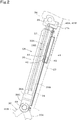
- the working tool cylinder C5 and the arm 23 are provided therebetween with a detection device (or a position sensor) 41 for detecting a swing position of the working tool 24.
- the swing position is defined as a position of the working tool 24 swinging around the working tool shaft 29. This position may correspond to the dump position P1, the crowd position P2, or any position between the dumping position P1 and the crowd position P2.
- Due to the pipeless hydraulic cylinder employed as the working tool cylinder C5, the working tool cylinder C5 and the arm 23 have a space without a pipe or a hose therebetween. This space is useful for arrangement of the detection device 41. Due to the arrangement of the detection device 41 between the working tool cylinder C5 and the arm 23, the detection device 41 is prevented from being damaged.
- the detection device 41 detects a telescopic movement state (or a stroke length) of the working tool cylinder C5, thereby detecting the swing position of the working tool 24.
- the detection device 41 includes a detected object 42 provided on the cylinder tube 36 and a detector 43 provided on the piston rod 37.
- the detector 43 while moving together with the piston rod 37, detects the detected object 42, thereby detecting the telescopic movement state of the working tool cylinder C5.
- the detected object 42 may be provided on the piston rod 37 and the detector 43 may be provided on the cylinder tube 36.
- the detected object 42 is attached to an outer surface of the cylinder tube 36 facing the arm 23. Specifically, the detected object 42 is fastened with screws or so on to an attachment plate 44 fixed to the cylinder tube 36.
- the attachment plate 44 is disposed on the rod-side portion of the cylinder tube 36 and is fixed to the outer surface of the cylinder tube 36 facing the arm 23 by welding or so on.
- guide members including a first guide member 45A and a second guide member 45B are provided on the attachment plate 44.
- the attachment plate 44 has a first fitting portion 44A which protrudes leftward and is fittingly covered with the first guide member 45A.
- the attachment plate 44 has a second fitting portion 44B which protrudes rightward and is fittingly covered with the second guide member 45B.
- the first fitting portion 44A and the second fitting portion 44B are disposed close to a first end of the attachment plate 44 (i.e., an end of the attachment plate 44 on the rod-side of the cylinder tube 36).
- the detected object 42 includes a first detected object 42A and a second detected object 42B.
- the first detected object 42A is disposed on a left portion of the attachment plate 44, and the second detected object 42B is disposed on a right portion of the attachment plate 44.
- the first detected object 42A has a predetermined length in the longitudinal direction of the cylinder tube 36 such as to have a first end corresponding to the first end of the attachment plate 44 and a second end corresponding to a second end of the attachment plate 44 (i.e., another end of the attachment plate 44 on the bottom-side of the cylinder tube 36).
- the first detected object 42A includes a casing 46A and a plurality of magnets 47A.
- the casing 46A is formed to have the length corresponding to the whole length of the attachment plate 44 between the first and second ends of the attachment plate 44, and is fastened to the attachment plate 44 by screws or so on.
- the casing 46A may be made of a single member extending from a first end thereof to a second end thereof, or may be dividable into parts in the longitudinal direction thereof.
- the magnets 47A are provided inside of the casing 46A so that they are aligned at intervals from the first end of the casing 46A to the second end of the casing 46A.
- the magnets 47A may be replaced with a continuously formed magnet.
- the second detected object 42B is provided on a portion of the attachment plate 44 close to the first end of the attachment plate 44.
- the second detected object 42B includes a casing 46B and a single magnet 47B.
- the second detected object 42B may be omitted.
- the second detected object 42B may be formed to have the same length as that of the first detected object 42A, and may be disposed to positionally coincide to the fist detected object 42A in the longitudinal direction of the cylinder tube 36.
- the detector 43 includes a first sensor 43A and a second sensor 43B.
- the first sensor 43A and the second sensor 43B function as proximity sensors and as magnetic sensors for detecting magnetism.
- the first sensor 43A and the second sensor 43B are disposed to have a space therebetween in the machine width direction and are disposed to positionally coincide to each other in the longitudinal direction of the cylinder tube 36.
- the first sensor 43A corresponds to the first detected object 42A so as to detect the first detected object 42A.
- the first sensor 43A includes a base member 48A movable together with the piston rod 37, and a detection element 49Afor detecting the magnets 47A. While the base member 48A moves together with the piston rod 37, the detection element 49A scans the magnets 47A one after another, thereby detecting any portion of the first detected object 42A between the first and second ends of the first detected object 42A.
- the second sensor 43B corresponds to the second detected object 42B so as to detect the second detected object 42B.
- the second sensor 43B includes a base member 48B movable together with the piston rod 37, and a detection element 49B for detecting the magnet 47B. Due to the movement of the base member 48B together with the piston rod 37, the detection element 49B detects a portion of the second detected object 42B between first and second ends of the second detected object 42B.
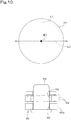
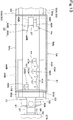
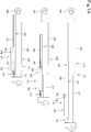
- FIGS. 5 and 6 and the lowest drawing of drawings in FIG. 9 illustrate the working tool cylinder C5 in the fully contracted state.
- the working tool 24 is disposed at the dump position P1 (see FIG. 3 ).
- the detector 43 is disposed at a first position P4 corresponding to the second end of the first detected object 42A.
- the first sensor 43A detects the first detected object 42A while the second sensor 43B does not detect the second detected object 42B.
- the detector 43 moves together with the piston rod 37.
- the first detected object 42A keeps detecting the first detected object 42A until the detector 43 reaches a second position P5 corresponding to the first end of the first detected object 42A as illustrated by the middle drawing of FIG. 9 .
- the second sensor 43B detects the second detected object 42B while the detector 43 moves from a position slightly before the second position P5 to the second position P5.
- the position of the working tool 24, when the detector 43 is disposed at the second position P5, is referred to as a first predetermined position P3 (see FIG. 3 ).
- the first sensor 43A detects the first detected object 42A and the second sensor 43B detects the second detected object 42B, thereby enhancing the reliability of the detection device 41 when at the second position P5 and in the vicinity thereof.
- the detector 43 no further detects the detected object 42 until the working tool cylinder C5 is fully extended as illustrated by the highest drawing in FIG. 9 .
- the first predetermined position P3 is set between the dump position P1 and the crowd position P2, and the detection device 41 detects the existence of the working tool 24 when it is in a predetermined range E1 between the first predetermined position P3 and the dump position P1.
- the predetermined range E1 ranges from the first predetermined position P3 to the dump position P1.
- a reference numeral T1 designates a movement locus of the tip end portion 24B of the working tool 24 swinging from the dump position P1 to the crowd position P2, and a reference numeral O1 designates a middle point of the movement locus T1.
- the movement range of the tip end portion 24B from the middle point O1 to the dump position P1 is defined as a dump side in the swing range of the working tool 24, and the movement range of the tip end portion 24B from the middle point O1 to the crowd position P2 is defined as a crowd side in the swing range of the working tool 24.
- the detection device 42 detects the existence of the working tool 24 when it is in the predetermined range E1 on the dump side in the swing range thereof.
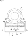
- the attachment structure 51 includes a detector mount 52, to which the detector 43 is attached, and a connection mechanism 53 to connect the detector mount 52 to the piston rod 37.
- the detector mount 52 includes a mount main body 54, a supporter 55 for supporting the mount main body 54 on the attachment plate 44, and a cover plate 56 for covering the detected object 42.
- the mount main body 54 includes a base wall 54a, a first side wall 54b, a second side wall 54c, a first end wall 54d and a second end wall 54e.
- the base wall 54a is disposed between the working tool cylinder C5 and the arm 23.
- the first side wall 54b extends from a left end of the base wall 54a.
- the second side wall 54c extends from a right end of the base wall 54a.
- the first end wall 54d is provided on a first end portion of the base wall 54a, i.e., an end portion of the base wall 54a on the rod-side of the cylinder tube 37.
- the second end wall 54e is provided on a second end portion of the base wall 54a, i.e., another end portion of the base wall 54a on the bottom-side of the cylinder tube 37.
- the base wall 54a faces the detected object 42 when the working tool cylinder C5 is fully contracted.
- An attachment block 57 is fixed to the second end portion of the base wall 54a.
- the first sensor 43A is attached to the left side of the attachment block 57.
- the second sensor 43B is attached to the right side of the attachment block 57.
- the supporter 55 includes a first slide member 55A on the left side thereof, and includes a second slide member 55B on the right side thereof.
- the first slide member 55A is formed to have a rightward open groove into which the first fitting portion 44A is fitted so that the first slide member 55A is movable relative to the attachment plate 44 in the longitudinal direction of the cylinder tube 36.
- the second slide member 55B is formed to have a leftward open groove into which the second fitting portion 44B is fitted so that the second slide member 55B is movable relative to the attachment plate 44 in the longitudinal direction of the cylinder tube 36.
- the first slide member 55A is fixed to the first side wall 54b, and the second slide member 55B is fixed to the second side wall 54c. Accordingly, the attachment block 57 is supported by the attachment plate 44 via the supporter 55 movably relative to the attachment plate 44 in the longitudinal direction of the cylinder tube 36.
- the supporter 55 protrudes from the mount main body 54 to the bottom side and to the rod side.
- the portion of the supporter 55 protruding to the bottom side from the mount main body 54 extends from the detector mount 52 to the vicinity of a cover member 58 covering a grease nipple as shown in the lowest drawing in FIG. 9 .
- the cover plate 56 is disposed on the side of the attachment plate 44 opposite to the working tool cylinder C5 so as to connect the first slide member 55A and the second slide member 55B to each other. Referring to FIG. 5 , the cover plate 56 is fixed at a first end thereof to the second end wall 54e of the mount main body 54.
- the cover plate 56 is extended to have a second end defining an end portion of the supporter 55.
- the cover plate 56 moves together with the piston rod 37 so as to cover the detected object 42.
- the connection mechanism 53 includes a first connection piece 59, a second connection piece 60 and a connection pin 61.
- the first connection piece 59 is joined to the piston rod 37.
- the first connection piece 59 is fixed to a fixture plate 62 attached to the rod head 37A.
- the second connection piece 60 is joined to the mount main body 54 (of the detector mount 52).
- the second connection piece 60 includes a first portion 60a and a second portion 60b.
- the first portion 60a is fixed to the first end wall 54d of the mount main body 54 so as to connect the first slide member 55A and the second slide member 55B to each other.
- the second portion 60b extends from the first portion 60a toward the rod head 37A.
- connection pin 61 is passed through the first connection piece 59 and the second connection piece 60 so as to couple the first and second connection pieces 59 and 60 to each other.
- the second connection piece 60 and the second portion 60b of the first connection piece 59 face each other in the radial direction of the piston rod 37 so as to have a space 63 therebetween, and the connection pin 61 is passed through the space 63.
- the first connection piece 59 is formed with a first pin hole 64 through which the connection pin 61 is passed.
- the first pin hole 64 is formed into a long hole shape such as to allow the piston rod 37 to rotate around an axis B1 of the piston rod 37.
- an extension line L1 of the axis of the connection pin 61 is perpendicular to the axis of the piston rod 37.
- the long hole serving as the first pin hole 64 elongates parallel to a direction L2 perpendicular to the extension line L1 and the axis B1.
- the second portion 60b of the first connection piece 59 is formed with a second pin hole 65 through which the connection pin 61 is passed.
- the second pin hole 65 is formed into a circular hole shape.
- the piston rod 37 Due to backlash of the cylinder shaft 35 in a cylinder shaft passage hole penetrating the rod head 37A and the cylinder bracket 34, the piston rod 37 is allowed to slightly rotate around the axis B1 thereof so that the first connection piece 59 is allowed to swing according to the rotation of the piston rod 37.
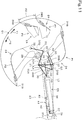
- FIGS. 11 to 14 illustrate an alternative embodiment.
- a second predetermined position P7 is set between a first predetermined position P6 and the dump position P1, and the detection device 41 detects the existence of the working tool 24 when it is in a predetermined range E2 ranging from the first predetermined position P6 to the second predetermined position P7.
- the first predetermined position P6 is defined as a position where an angle D3 between a line L3 connecting the axial center of the cylinder shaft 35 to the axial center of the connection shaft 33 and a line L4 connecting the axial center of the first link shaft 31 to the axial center of the connection shaft 33 becomes a substantially right angle.
- the detector 43 is separated from the detection device 42 so that the detection device 41 does not detect the working tool C5. While the working tool cylinder C5 is extended from the fully contracted state, the detection device 41 does not detect the working tool C5 before the first sensor 43A reaches a position corresponding to the second end of the first detected object 42A.
- the detection device 41 detects the existence of the working tool 24 at the second predetermined position P7. While the working tool cylinder C5 is extended further from this extension state, the working tool 24 is detected until the detector 43 reaches a position corresponding to the first end of the detected object 42. When the detector 43 reaches the position corresponding to the first end of the detected object 42 and detects the first detected object 42A and the second detected object 42B, the detection device 41 detects the existence of the working tool 24 at the second predetermined position P7. Accordingly, while the working tool 24 is in the predetermined range E2 ranging from the first predetermined position P6 to the second predetermined position P7, the detection device 41 detects the existence of the working tool 24 in the predetermined range E2.
- lowest, middle and highest drawings indicate different telescopic movement states of the working tool cylinder C5.
- the lowest drawing illustrates the working tool cylinder C5 when it is fully contracted.
- the middle drawing illustrates the working tool cylinder C5 when the working tool 24 is located at the first predetermined position P6.
- the highest drawing illustrates the working tool cylinder C5 when it is fully extended.
- the detected object 42 is covered with the cover plate 56 without protruding from the cover plate 56 even when the working tool cylinder C5 is fully extended.
- the detection device 41 and the attachment structure 51 are identical or similar to those shown in FIGS. 7 , 8 , 12 and 13 . Illustration and description of the structures identical or similar to those of the foregoing embodiments will be omitted.
- the working machine 1 includes a controller 71 for controlling the swing of the bucket (working tool) 24, and includes a bucket control valve 72 for controlling the bucket cylinder C5.
- the controller 71 is constituted by a microcomputer including CPU (Central Processing Unit) and EEPROM (Electrically Erasable Programmable Read-Only Memory), for example.
- the bucket control valve 72 is a control valve electrically controlled by the controller 71.
- a proportional directional solenoid valve serves as the bucket control valve 72.
- the proportional directional solenoid valve is a valve in which a main spool is moved by a solenoid to control the flow of hydraulic fluid.
- the bucket control valve 72 is a three position shift valve shiftable among a neutral position 72a, a first position 72b and a second position 72c.
- the bucket control valve 72 includes a first solenoid 72d and a second solenoid 72e.
- the first solenoid 72d and the second solenoid 72e are electrically connected to the controller 71 so that each of the first and second solenoids 72d and 72e is excited or unexcited according to a command signal outputted from the controller 71. Due to the excitation or non-excitation of each of the first and second solenoids 72d and 72e, the bucket control valve 72 is shiftable from the neutral position 72a to either the first position 72b or the second position 72c.
- the bucket control valve 72 is fluidly connected to a hydraulic pump 92 via a supply fluid passage 73A, and to a tank 74 via a drain fluid passage 73B.
- the bucket control valve 72 is fluidly connected to the piston rod 37 of the bucket cylinder C5 via a first cylinder fluid passage 73C and a second cylinder fluid passage 73D.
- the first cylinder fluid passage 73C is fluidly connected to the first fluid passage 39A
- the second cylinder fluid passage 73D is fluidly connected to the second fluid passage 39B.
- an operation member 75 for operating the bucket 24 is electrically connected to the controller 71.
- the controller 71 can obtain an operation signal (electric signal) from the operation member 75.
- the operation member 75 is disposed adjacent to the operator seat 6 and includes a lever 76 which can be gripped and operated by an operator.
- the lever is swingable from its neutral position in first and second directions opposite to each other. For example, when the level 76 is swung in the first direction, the first solenoid 72d is excited to shift the bucket control valve 72 to the first position 72b. Due to the shift of the bucket control valve 72 to the first position 72b, the bucket cylinder C5 is contracted to swing the bucket 24 in the dump direction Y1.
- the second solenoid 72e When the level 76 is swung in the second direction, the second solenoid 72e is excited to shift the bucket control valve 72 to the second position 72c. Due to the shift of the bucket control valve 72 to the second position 72c, the bucket cylinder C5 is extended to swing the bucket 24 in the crowd direction Y2. When the lever 76 is returned to its neutral position, the bucket control valve 72 returns to the neutral position 72a to stop the telescopic movement of the bucket cylinder C5, i.e., to stop the movement of the bucket 24.
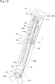
- the bucket cylinder C5 when in a fully contracted state 77, is disposed parallel and adj acent to the arm 23. Assuming that the bucket cylinder C5 is extended from the fully contracted state 77 to a fully extended state 78, in a first stage of the extension movement of the bucket cylinder C5, the bucket cylinder C5 swings away from the arm 23 so as to increase a swing angle G of the bucket cylinder C5. After passing a halfway point of the extension movement of the bucket cylinder C5, the swing direction of the bucket cylinder C5 relative to the arm 23 is reversed so that the bucket cylinder C5 approaches the arm 23 so as to gradually reduce the swing angle G of the bucket cylinder C5. In FIG.
- a reference numeral 79 designates a turning point as the halfway point of extension or contraction movement of the bucket cylinder C5, where the variation direction of the swing angle G of the bucket cylinder C5 is reversed between the increasing direction and the reducing direction, i.e., where the swing angle G becomes maximum.
- a reference numeral P6 designates a position of the bucket 24 when the bucket cylinder C5 is at the turning point 79.
- the following description is given on an assumption that the state where the bucket cylinder C5 is disposed at the turning point 79 and the bucket 24 is disposed at the position P6 is referred to as a neutral position 80.
- the neutral position 80 is conceptual. Referring to FIG. 16 , the neutral position 80 corresponding to the turning point 79 of the bucket cylinder C5 defines the border between the dump side E3 and the crowd side E4 in the swing range of the bucket 24.
- an angle sensor 81 is attached to the cylinder bracket 34 so as to detect the swing angle G of the bucket cylinder C5 around the cylinder shaft 35.
- the angle sensor 81 is constituted by a potentiometer, for example.
- the angle sensor 81 detects a swing angle G1 on the dump side E3 from the neutral position 80 and a swing angle G2 on the crowd side E4 from the neutral position 80.
- the angle sensor 81 is linked to the rod head 37A of the bucket cylinder C5 by a linkage 82. Accordingly, the angle sensor 81 with the linkage 82 detects the rotation of the rod head 37A around the cylinder shaft 35, thereby detecting the swing angel G of the bucket cylinder C5 around the cylinder shaft 35.
- the angle sensor 81 may have no linkage to directly detect the rotation of the bucket cylinder C5 around the cylinder shaft 35.
- the angle sensor 81 is electrically connected to the controller 71.
- the controller 71 can obtain a detection value (or a potentiometer resistance value) from the angle sensor 81.
- the controller 71 includes a calculation unit 83.
- the calculation unit 83 calculates the swing position of the bucket 24 based on the swing angle G of the bucket cylinder C5, i.e., the potentiometer resistance value.
- the swing position of the bucket 24 is defined as any position of the bucket 24 swinging around the bucket shaft 29.
- the detection device 41 is provided to detect whether the bucket 24 is on the dump side E3 or the crowd side E4 with respect to the neutral position 80.
- the calculation unit 83 of the controller 71 calculates or determines the swing position of the bucket 24 based on the swing angle G detected by means of the angle sensor 81 and detection information as a result of detection by means of the detection device 41.
- the detection device 41 detects ON and OFF signals such as to detect the position of the piston rod 37 relative to the cylinder tube 36 during the telescopic movement of the bucket cylinder C5.
- the detector 43 when detecting the detected object 42, outputs a detection signal to the controller 71.
- the detection signal may be either the on signal or the off signal.
- FIGS. 12 and 13 and the lowest drawing of drawings in FIG. 19 illustrate the bucket cylinder C5 when in the fully contracted state 77.
- the detector 43 is located at the first position P4 corresponding to the second end of the first detected object 42A.
- the detector 43 is separated away from the detected object 42 so that the first sensor 43A does not detect the first detected object 42A and the second sensor 43B does not detect the second detected object 42B.
- the detector 43 moves together with the piston rod 37.
- the first sensor 43A detects the first detected object 43A.
- the second sensor 43B detects the second detected object 42B.
- the state where the first sensor 43A detects the first detected object 42A and the second sensor 43B detects the second detected object 42B is defined as the neutral position 80.
- the detector 43 detects the neutral position 80 by detecting the detectable end of the second detected object 42B of the detected object 42.
- the detection of the neutral position 80 requires both the detection of the first detected object 42A by means of the first sensor 43A and the detection of the second detected object 42B by means of the second sensor 43B, thereby enhancing the reliability of the detection device 41.
- the second detected object 42B and the second sensor 43B may be omitted.
- the detection device 41 is electrically connected to the controller 71.
- the controller 71 can obtain detection information from the detection device 41.
- the controller 71 includes a determination unit 84 such that, based on the detection information from the detection device 41, the determinement unit 84 determines whether the bucket 24 exists on the dump side E3 or the crowd side E4 with respect to the neutral position 80.
- the working machine 1 includes a switch 85, serving as an instruction input unit, for receiving an instruction input from the operator, the instruction input indicating whether the bucket 24 is on the dump side E3 or the crowd side E4.
- the switch 85 is disposed adjacent to the operator seat 6.
- the switch 85 is electrically connected to the controller 71.
- the controller 71 can obtain an electric signal from the switch 85.
- the controller 71 includes a storage unit 86.
- the detection device 41 is arranged so that it can find whether the bucket 24, when existing in a detectable range that is a predetermined range as the vicinity of the neutral position 80, is on the dump side E3 or the crowd side E4.
- the detection device 41 serves as a sensor for judging whether the bucket 24 exists on the dump side E3 or the crowd side E4 with respect to the neutral position 80.
- the detection information from the detection device 41 is used to determine the swing position of the bucket 24.
- a position confirmation operation i.e., an initial position determining operation, to determine whether the bucket 24 exists on the dump side E3 or the crowd side E4 is performed while the bucket 24 is out of the predetermined range as the vicinity of the neutral position 80.
- the position confirmation operation is performed in the following way.
- the operator temporarily moves the bucket 24 to the dump side E3 or the crowd side E4.
- the operator pushes the switch 85 to inform the controller 71 that the bucket 24 is disposed at the dump position P1 on the dump side E3.
- the operator pushes the switch 85 to inform the controller 71 that the bucket 24 is disposed at the crowd position P2 on the crowd side E4.
- the controller 71 when informed of the position of the bucket 24, makes the storage unit 86 store the informed position of the bucket 24.
- the controller 71 may automatically recognize whether the bucket 24 exists on the dump side E3 or the crowd side E4. Specifically, after the bucket 24, temporarily swung to the dump side E3 or the crowd side E4, reaches the dump position P1 or the crowd position P2, the resistance value of the potentiometer serving as the angle sensor 81 varies no further from that corresponding to the bucket 24 at the dump position P1 or the crowd position P2. Therefore, if the state where the resistance value no further varies continues for a predetermined period, the controller 71 may automatically detect that the bucket 24 is disposed at the dump position P1 or the crowd position P2. The controller 71, when automatically recognizing the position of the bucket 24, makes the storage unit 86 store the recognized position of the bucket 24.
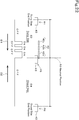
- a detectable range 87 for the detector 43 to detect the detected object 42 ranges from the neutral position 80 to an intermediate position between the neutral position 80 and the end position on the dump side E3.
- the detection device 41 when in the detectable range 87, is turned on, while the detection device 41, when out of the detectable range 87, i.e., when in a first undetectable range 88 or a second undetectable range 89, is turned off.
- the neutral position 80 is defined as a border between the turn-on range and the turn-off range.
- the voltage of the angle sensor 81 when detecting the swing angle of the bucket cylinder C5 in the vicinity of the neutral position 80, is known.
- the determination unit 84 determines the bucket 24 as being on the dump side E3. If the angle sensor 81 is turned off while the voltage of the angle sensor 81 indicates that when detecting in the vicinity of the neutral position 80, the determination unit 84 determines the bucket 24 as being on the crowd side E4.
- the detection device 41 is turned on as soon as the detector 43 enters the detectable range 87.
- the detection device 41 is turned off. Accordingly, the determination unit 84 determines the bucket 24 as being on the crowd side E4.
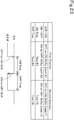
- a first detection pattern appearing in the ON/OFF signal detection by means of the detection device 41 during the movement of the bucket 24 (or the piston rod 37) in the first direction D1 is indicated as "OFF-to-ON-to-OFF" ("Non-detection to Detection to Non-detection").
- the result of determination by the determination unit 84 is stored in the storage unit 86.
- the controller 71 keeps the determination, stored in the storage unit 86, that the bucket 24 is on the crowd side E4 until the detector 43 reaches a point immediate before the neutral position 80.
- the detection device 41 having been turned off is turned on so that the determination unit 84 determines the bucket 24 as being on the dump side E3.
- a second detection pattern appearing in the ON/OFF signal detection by means of the detection device 41 during the movement of the bucket 24 (or the piston rod 37) in the second direction D2 is indicated as "OFF-to-ON" ("Non-detection to Detection”).
- the controller 71 makes the storage unit 86 store the result of determination that the backet 24 is on the dump side E3. Afterward, while the piston rod 37 is moved in the second direction D2 and when the piston rod 37 is stopped with the detector 43 left in the first undetectable range 88, the controller 71 keeps the state stored in the storage unit 86, i.e., the state of the bucket 24 being on the dump side E3.
- the detector 43 leaves the detectable range 87 and enters either the first undetectable range 88 or the second undetectable range 89, thereby causing "ON-to-OFF" pattern. For this reason, the detection device 41 alone is insufficient to determine whether the detector 43 enters the first undetectable range 88 or the second undetectable range 89.
- the detectable range 87 has a first detectable range end 87a corresponding to the neutral position 80 and a second detectable range end 87b opposite to the first detectable range end 87b
- a potentiometer resistance value generated at the second detectable range end 87b is considered to determine the detector 43 as entering the first undetectable range 88.
- the detection device 41 when in the detectable range 87, may be turned off, and the detection device 41, when out of the detectable range 87, may be turned on.
- the first detection pattern realized by means of the detection device 41 when the piston rod 37 is moved in the first direction D1 is indicated as "ON-to-OFF-to-ON” (corresponding to "Non-detection to Detection to Non-detection”).
- the second detection pattern realized by means of the detection device 41 when the piston rod 37 is moved in the second direction D2 is indicated as "ON-to-OFF” (corresponding to "Non-detection to Detection") pattern.
- the detectable range 87 for the detector 43 to detect the detected object 42 may range from the neutral position 80 to an intermediate position between the neutral position 80 and the end position on the crowd side E4.
- the detection device 41 detects ON and OFF signals indicating whether the bucket cylinder C5 is extended or contracted from the neutral position 80.
- Each of the first detection pattern and the second detection pattern is a combination of ON-to-OFF and OFF-to-ON signal shifts, and the combination as the first detection pattern and the combination as the second detection pattern are different from each other.
- the working machine 1 includes a display unit (or a meter panel) 90.
- the display unit 90 is disposed adjacent to the operator seat 6 visually from the operator.
- the display unit 90 is electrically connected to the controller 71.
- the display unit 90 may be provided with the switch 85.
- the controller 71 includes a command unit 91.
- the controller 71 stores the position of the bucket 24 on either the dump side E3 or the crowd side E4, and defines the stored position of the bucket 24 as an initial position for restart of the operation of the bucket 24.
- the controller 71 determines whether the bucket 24 is on the dump side E3 or the crowd side E4 with respect to the neutral position 80. For example, the controller 71 makes the storage unit 86 store the position of the bucket 24 at the time immediate before a key switch is turned off.
- the controller 71 views the position of the bucket 24 stored in the storage unit 86 so as to determine whether the bucket 24 is on the dump side E3 or the crowd side E4 with respect to the neutral position 80. It is greatly convenient because the operator does not have to perform the position confirmation operation after the key switch is turned on.
- the controller 71 informs the operator of the uncertainness in position of the bucket, i.e., commands the display unit 90 to display a message for urging the operator to perform the position confirmation operation to determine whether the bucket 24 is on the dump side E3 or the crowd side E4.
- the command unit 91 commands the display unit 90 to display a message for urging the operator to move the bucket 24 to the dump side E3 or the crowd side E4.
- the display unit 90 displays the message for urging the operator to locate the bucket 24 at any position on either the dump side E3 or the crowd side E4 and to register the position defined as the initial position. Therefore, the operator is only required to perform the position confirmation operation.
- FIG. 21 illustrates a first modification of the embodiment shown in FIGS. 15 to 20 .
- two detected objects 42 i.e., detected objects 42L and 42R
- the detected object 42L is disposed to be detectable when the bucket 24 is on the dump side E3.
- the detected object 42R is disposed to be detectable when the bucket 24 is on the crowd side E4.
- the neutral position 80 defines a border between two detectable ranges, i.e., a first detectable range 87A and a second detectable range 87B.
- An interval (or a distance) W1 between the first detectable range 87A and the neutral position 80 is different from an interval (or a distance) W2 between the second detectable range 87B and the neutral position 80.
- the angle sensor 81 outputs a detection value (i.e., an angle sensor value) corresponding to the swing angle of the bucket cylinder C5. Therefore, based on the detection value of the angle sensor 81 at the time of the ON/OFF shift of the detection device 41, the controller 71 determines whether the bucket 24 is on the dump side E3 or the crowd side E4 with respect to the neutral position 80.
- the detected objects 42L and 42R are illustrated to have the interval therebetween, however, the configuration is not limited to the illustrated configuration.
- the only requirement is that the detection value of the angle sensor 81 when the bucket 24 is at a position corresponding to one ON/OFF shift point in detection by means of the detection device 41 is different from that when the bucket 24 is at another position corresponding to the other ON/OFF shift point in detection by means of the detection device 41.
- the above-mentioned determination may be performed by using times t1 and t2.
- the first detectable range 87A has a detectable range end 87Aa closer to the neutral position 80 than the other end thereof, and the time t1 is defined as a time taken for movement of the detector 43 through the first detectable range 87A from the detectable range end 87Aa to the neutral position 80.
- the second detectable range 87B has a detectable range end 87Ba closer to the neutral position 80 than the other end thereof, and the time t2 is defined as a time taken for movement of the detector 43 through the second detectable range 87B from the detectable range end 87Ba to the neutral position 80.
- the times t1 and t2 are calculated based on the distances W1 and W2 from the neutral position 80 and the swing speed of the bucket 24, and are inputted to the controller 71.
- the detection device 41 is turned on when the detector 43 detects the detected object 42L.
- the first detection pattern appearing in detection by means of the detection device 41 when the piston rod 37 is moved in the first direction D1 is indicated as "OFF-to-ON-to-OFF" with the time t1.
- the bucket 24 can be determined as moving from the dump side E3 to the crowd side E4 and then being on the crowd side E4.
- the second detection pattern appearing in detection by means of the detection device 41 when the piston rod 37 is moved in the second direction D2 is indicated as "OFF-to-ON-to-OFF" with the time t2. Based on this detection pattern, the bucket 24 can be determined as moving from the crowd side E4 to the dump side E3 and then being on the dump side E3.
- the bucket 24 may be determined as being on the same side with the last detected detected object 42L or 42R.
- the detection device 41 may be turned off when the detector 43 detects either the detected object 42L or 42R.
- each of the first and second detection patterns may be a combination of ON-to-OFF and OFF-to-ON signal shifts with the turn-on time and the turn-off time, while the combination as the first detection pattern and the combination as the second detection pattern are different from each other.
- FIG. 22 illustrates a second modification different from the first modification of FIG. 21 .
- the detected object 42 includes a plurality of divisional members 42a to 42c which are offset from one another in the longitudinal direction of the bucket cylinder C5 so as to have intervals thereamong.
- Constitution elements of the first and second modifications except for those mentioned above are identical or similar to those of the embodiment shown in FIGS. 15 to 20 .
- each of the first and second detection patterns may be a combination of the ON-to-OFF signal shift and the OFF-to-ON signal shift, while the combination as the first detection pattern and the combination as the second detection pattern are different from each other.
- each of the first and second detection patterns may be a combination of ones selected from a group consisting of the ON-to-OFF signal shift, the OFF-to-ON signal shift, the turn-on time and the turn-off time, while the combination as the first detection pattern and the combination as the second detection pattern are different from each other.
- the ON-to-OFF signal shift the OFF-to-ON signal shift
- the turn-on time the turn-off time
- a combination of an ON-to-OFF shifts count B1, an OFF-to-ON shifts count B2, a time B3 and a time B4 during movement of the piston rod 37 in the first direction D1 is different from a combination of an ON-to-OFF shifts count F1, an OFF-to-ON shifts count F2, a time F3 and a time F4 during movement of the piston rod 37 in the second direction D2.
- the bucket cylinder C5 is hydraulically controlled by the bucket control valve 72 which is operated by an electric signal outputted from the controller 71. Therefore, it can be grasped by means of the controller 71 whether the bucket 24 is moved to the dump side E3 or the crowd side E4.
- the voltage of the potentiometer serving as the angle sensor 81 becomes low when the bucket 24 is in the vicinity of the end of its swing range end, and the voltage becomes high when the bucket 24 is in the vicinity of the neutral position 80.
- the voltage of the angle sensor 81 varies in the increasing direction during the swing of the bucket 24 in the dump direction Y1 by means of the first solenoid 72d excited by the controller 71, the bucket 24 is determined as being on the crowd side E4 with respect to the neutral position 80.
- the voltage of the angle sensor 81 varies in the reducing direction during the swing of the bucket 24 in the dump direction Y1
- the bucket 24 is determined as being on the dump side E3 with respect to the neutral position 80.
- the bucket 24 is determined as being on the dump side E3 with respect to the neutral position 80. If the voltage of the angle sensor 81 varies in the reducing direction during the swing of the bucket 24 in the crowd direction Y2, the bucket 24 is determined as being on the crowd side E4 with respect to the neutral position 80.
- the operation member 75 for operating the bucket 24 may be used.
- the controller 71 obtains an electric signal from the operation member 75. Therefore, when the lever 76 is operated in one direction to swing the bucket 24 in the dump direction Y1, if the voltage of the angle sensor 81 varies in the increasing direction, the bucket 24 is determined as being on the crowd side E4 with respect to the neutral position 80, and if the voltage of the angle sensor 81 varies in the reducing direction, the bucket 24 is determined as being on the dump side E3.
- the working machine 1 has the following effects:
- the working machine 1 comprises the support member (or the arm 23), the supported member (or the working tool 24) pivotally supported by the first end portion of the support member (or the arm 23) via the pivot, and the cylinder (or the working tool cylinder C5) of which telescopic movement causes the supported member (or the working tool 24) to swing around the pivot (or the working tool shaft 29).
- the cylinder (or the working tool cylinder C5) includes the cylinder tube 36, and the piston rod 37 inserted into the cylinder tube 36.
- the cylinder (or the working tool cylinder C5) is constituted by the hydraulic cylinder telescopically moved by extension and contraction movement of the piston rod 37 with respect to the cylinder tube 36 by hydraulic fluid flowing through the fluid passage formed in the piston rod 36.
- the cylinder tube 37 is pivotally supported by one of the first and second end portions of the support member (or the arm 23), and the piston rod 36 is pivotally supported by the other of the first and second end portions of the support member (or the arm 23).
- the detection device 41 for detecting the telescopic movement state of the cylinder (or the working tool cylinder C5) is provided between the cylinder (or the working tool cylinder C5) and the support member (or the arm 23).
- the cylinder (or the working tool cylinder C5) is constituted by the hydraulic cylinder telescopically moved by hydraulic fluid flowing through the fluid passage formed in the piston rod 37 so that the cylinder (or the working tool cylinder C5) and the support member (or the arm 23) have a space therebetween without a pipe or a hose.
- the detection device 41 disposed in the space is advantageously prevented from being damaged in comparison with the detection device 41 when provided on a portion pivotally supporting the supported member (or the working tool 24).
- the space is effectively usable so that the detection device 41 disposed in the space is prevented or reduced from spoiling the appearance of the working machine, and from increasing the size thereof.
- the working machine 1 may comprise the machine body 2 and the boom 22 swingably attached to the machine body 2.
- the support member may be the arm 23 pivotally supported at the basal end portion thereof by the boom 22.
- the supported member may be the working tool 24 pivotally supported by the tip end portion of the arm 22 via the pivot (or the working tool shaft 29).
- the cylinder may be the working tool cylinder C5 for swinging the working tool 24 around the pivot.
- the working tool cylinder C5 is constituted by the hydraulic cylinder telescopically moved by hydraulic fluid flowing through the fluid passage in the piston rod 37, the working tool cylinder C5 and the arm 23 have a space therebetween without a pipe or a hose. Therefore, the detection device 41 disposed in the space is prevented or reduced from being damaged.
- the detection device 41 includes the detected object 42 provided on one of the cylinder tube 36 and the piston rod 37, and the detector 43 provided on the other of the cylinder tube 36 and the piston rod 37.
- the detector 43 detects the detected object 42 for detection of the telescopic movement state of the cylinder.
- the detection device 41 can be compactly disposed between the working tool cylinder C5 and the arm 23.
- the detected object 42 is attached onto the outer surface of the cylinder tube 37 facing the arm 23.
- the detected object 42 has the predetermined length in the longitudinal direction of the cylinder tube 36, and includes the magnets 47A and 47B.
- the detector 43 is constituted by the proximity sensor, which is attached to the piston rod 37 between the cylinder tube 36 and the arm 23 so as to be able to face the detected object 42, and which is configured to move together with the piston rod 37 to detect the magnet 47A or 47B.
- the detection device 41 can be configured simply and economically.
- the working machine 1 comprises the detector mount 52 to which the detector 43 is attached, and the connection mechanism 53 connecting the detector mount 52 to the piston rod 37.
- the piston rod 37 includes the first connection piece 59 joined to the piston rod 37, the second connection piece 60 joined to the detection attachment member 52, and the connection pin 61 passed through the first connection piece 59 and the second connection piece 60 so as to connect the first connection piece 59 and the second connection piece 60 to each other.
- the pin hole (or the first pin hole 64) is formed in the connection piece 59 to allow the connection pin 61 to pass therethrough.
- the pin hole is formed into the long hole shape to allow axial rotation of the piston rod 37.
- the simple connection mechanism 53 prevents the piston rod 37 from being damaged because of the axial rotation of the piston rod 37.
- the working machine 1 comprises the arm 23, the bucket (or the working tool) 24 pivotally and swingably supported by the tip end portion of the arm 23, the bucket cylinder (or the working tool cylinder) C5 pivotally supported by the arm 23 via the cylinder shaft 35, the telescopic movement of the bucket cylinder C5 causing the bucket 24 to swing, the angle sensor 81 which detects the swing angle G1 of the bucket cylinder C5 when the bucket 24 is disposed on the dump side E3 with respect to the neutral position 80 where the swing angle G of the bucket cylinder C5 around the cylinder shaft 35 becomes maximum, and which detects the swing angle G2 of the bucket cylinder C5 when the bucket 24 is disposed on the crowd side E4 with respect to the neutral position 80, the detection device 41 which detects ON and OFF signals indicating whether the bucket cylinder C5 is extended further from the neutral position 80 or is contracted further from the neutral position 80, and the controller 71 for determining the swing position of the bucket 24 based on the swing angle G detected by means of the angle sensor 81 and the result of detection
- the controller 71 determines whether the bucket 24 is on the dump side E3 or the crowd side E4 in accordance with the first detection pattern appearing in detection of the ON and OFF signals by means of the detection device 41 when the bucket 24 is moved in the first direction D1 from the dump side E3 to the crowd side E4, and the second detection pattern appearing in detection of the ON and OFF signals by means of the detection device 41 when the bucket 24 is moved in the second direction D2 from the crowd side E4 to the dump side E3.
- the swing position of the working tool 24 can be accurately calculated based on the swing angle of the bucket cylinder C5 detected by means of the angle sensor 81 and the result of detection by means of the detection device 41.
- the controller 71 determines whether the bucket 24, when in the predetermined range as the vicinity of the neutral position 80, is on the dump side E3 or the crowd side E4.
- the position of the bucket 24 in the predetermined range as the vicinity of the neutral position 80 where the variation direction of the swing angle G is reversed can be determined while the angle sensor 81 alone is insufficient to determine the position.
- the controller 71 keeps the result of the determination regarding the position of the bucket 24 when in the predetermined range.
- the detection device 41 can be configured to detect the bucket 24 in only the predetermined range as the vicinity of the neutral position 80.
- the bucket cylinder 24 includes the cylinder tube 36, and the piston rod 37 extended and contracted with respect to the cylinder tube 36.
- the detection device 41 includes the detected object 42 provided on one of the cylinder tube 36 and the piston rod 37, and the detector 43 provided on the other of the cylinder tube 36 and the piston rod 37.
- the detector 43 outputs the on or off signal in response to whether the detected object 42 is detected or not.
- the position of the piston rod 37 with respect to the cylinder tube 36 facilitates the determination of the position of the bucket 24.
- Either the range ranging from the neutral position 80 to the intermediate position between the neutral position 80 and the end position on the dump side E3 or the range ranging from the neutral position 80 to the intermediate position between the neutral position 80 and the end position on the crowd side E4 is defined as the detectable range 87 where the detected object 42 is detectable by means of the detector 43.
- the length of the detected object 42 can be reduced, thereby minimizing the detection device 41.
- Each of the first detection pattern and the second detection pattern is a combination of ON-to-OFF and OFF-to-ON signal shifts.
- the combination as the first detection pattern and the combination as the second detection pattern are different from each other.
- the detection device has many variations.
- the controller 71 stores the result of determination of whether the bucket 24 is on the dump side E3 or the crowd side E4.
- the controller 71 defines the position of the bucket 24 stored on the ending of operation of the bucket 24 as the initial position for restarting of operation of the working tool, and performs the determination when the bucket cylinder C5 is extended or contracted from the initial position.
- the position of the bucket 24 does not have to be confirmed every restarting of operation of the bucket 24 after ending of the last operation of the bucket 24, thereby enhancing the convenience in operation of the bucket 24.
- the working machine comprises the display unit 90 connected to the controller 71.
- the display unit 90 displays the message for urging an operator to operate to locate the bucket 24 on either the dump side E3 or the crowd side E4.
- the controller 71 performs the determination based on the detection value outputted from the angle sensor 81 when the ON/OFF signal shift occurs in detection by means of the detection device 41.
- the controller 71 stores information indicating whether the bucket 24 is on the dump side E3 or the crowd side E4.
- the controller 71 determines the swing position of the bucket 24 based on the information stored on the last ending of operation of the bucket 24.
- the position of the bucket 24 does not have to be confirmed every restarting of operation of the bucket 24 after ending of the last operation of the bucket 24, thereby enhancing the convenience in operation of the bucket 24.
- the working machine comprises the instruction input unit (or the switch 85) for receiving the instruction input from an operator, the instruction input indicating whether the bucket 24 is on the dump side E3 or the crowd side E4.
- the operator can inform the controller 71 regarding whether the bucket 24 is on the dump side E3 or the crowd side E4.
Landscapes
- Engineering & Computer Science (AREA)
- General Engineering & Computer Science (AREA)
- Mining & Mineral Resources (AREA)
- Civil Engineering (AREA)
- Structural Engineering (AREA)
- Mechanical Engineering (AREA)
- Physics & Mathematics (AREA)
- Fluid Mechanics (AREA)
- Component Parts Of Construction Machinery (AREA)
- Operation Control Of Excavators (AREA)
Abstract
Description
- The present invention relates to a working machine such as a backhoe.
- The working machine disclosed in
Patent Document 1 is known. - The working machine disclosed in
Patent Document 1 includes a working device attached to a machine body thereof. The working device includes a boom swingably attached to the machine body, an arm swingably supported at a basal end portion thereof by the boom, and a working tool (e.g., a bucket) pivotally supported by a tip end portion of the arm via a pivot. A bucket cylinder (serving as a working tool cylinder) is pivotally supported by the arm via a cylinder shaft. The bucket is swung to a dump side and to a crowd side by telescoping the bucket cylinder. - The working machine includes a detection device for detecting the swing position of the working tool around the pivot. The detection device is provided on a pivotally supported portion of the working tool via the pivot.
- [Patent Document 1]
Japanese Unexamined Patent Publication No. 2011-252338 - The working machine disclosed in
Patent Document 1 has a problem such that the detection device is likely to be damaged because it is disposed on the pivotally supported portion of the working tool. - When the contracted bucket cylinder is extended, the bucket swings from the dump side to the crowd side. The bucket cylinder also swings around the cylinder shaft during its telescopic movement. As the bucket cylinder is extended from the fully contracted state thereof corresponding to the damp side end position of the bucket, the swing angle of the bucket cylinder around the cylinder shaft gradually increases until the extension stroke of the bucket cylinder reaches a halfway point, and the swing angle of the bucket cylinder gradually reduces reversely as the bucket cylinder is extended further from the halfway point.
- Therefore, the angle sensor for detecting the swing angle of the bucket cylinder, if it is alone, is insufficient to determine whether the bucket is disposed on the crowd side or the dump side with respect to the position (hereinafter, referred to as a "neutral position") where the swing angle becomes maximum.
- In consideration of the above problems, a first object of the present invention is to provide a detection device for detecting a swing position of a supported member, wherein the detection device is prevented from being damaged.
- A second object of the present invention is to provide a working machine capable of accurately calculating a swing position of a working tool based on a swing angle of a working tool cylinder detected by means of an angle sensor.
- In a first aspect of the present invention, a working machine comprises a support member, a supported member pivotally supported by an end portion of the support member via a pivot, and a cylinder of which telescopic movement causes the supported member to swing around the pivot. The cylinder includes a cylinder tube, and a piston rod inserted into the cylinder tube. The cylinder is constituted by a hydraulic cylinder telescopically moved by extension and contraction movement of the piston rod with respect to the cylinder tube by hydraulic fluid flowing through a fluid passage formed in the piston rod. The cylinder tube is pivotally supported by one of end portions of the support member, and the piston rod is pivotally supported by the other of the end portions of the support member. A detection device for detecting a telescopic movement state of the cylinder is provided between the cylinder and the support member.
- The working machine comprises a machine body, and a boom swingably attached to the machine body. The support member is an arm pivotally supported at a basal end portion thereof by the boom. The supported member is a working tool pivotally supported by a tip end portion of the arm via the pivot. The cylinder is a working tool cylinder for swinging the working tool around the pivot.
- The detection device includes a detected object provided on one of the cylinder tube and the piston rod, and a detector provided on the other of the cylinder tube and the piston rod. The detector detects the detected object for detection of the telescopic movement state of the cylinder.
- The detected object is attached onto an outer surface of the cylinder tube facing the support member. The detected object has a predetermined length in the longitudinal direction of the cylinder tube, and includes a magnet. The detector is constituted by a proximity sensor, which is attached to the piston rod between the cylinder tube and the support member so as to be able to face the detected object, and which is configured to move together with the piston rod to detect the magnet.
- The working machine comprises a detector mount to which the detector is attached; and a connection mechanism connecting the detector mount to the piston rod. The piston rod includes a first connection piece joined to the piston rod, a second connection piece joined to the detection attachment member, and a connection pin passed through the first connection piece and the second connection piece so as to connect the first connection piece and the second connection piece to each other. A pin hole is formed in the connection piece to allow the connection pin to pass therethrough. The pin hole is formed into a long hole shape to allow axial rotation of the piston rod.
- The working machine comprises an arm serving as the support member, a working tool serving as the supported member pivotally and swingably supported by a tip end portion of the arm, a working tool cylinder serving as the cylinder pivotally supported by the arm via a cylinder shaft, the telescopic movement of the working tool cylinder causing the working tool to swing, an angle sensor which detects a swing angle of the working tool cylinder when the working tool is disposed on a dump side with respect to a neutral position where a swing angle of the working tool cylinder around the cylinder shaft becomes maximum, and which detects a swing angle of the working tool cylinder when the working tool is disposed on a crowd side with respect to the neutral position, and a controller for determining the swing position of the working tool based on the swing angle detected by the means of angle sensor and a result of detection by means of the detection device. The detection device detects ON and OFF signals indicating whether the working tool cylinder is extended further from the neutral position or is contracted further from the neutral position. The controller determines whether the working tool is on the dump side or the crowd side in accordance with a first detection pattern appearing in detection of the ON and OFF signals by means of the detection device when the working tool is moved in a first direction from the dump side to the crowd side, and a second detection pattern appearing in detection of the ON and OFF signals by means of the detection device when the working tool is moved in a second direction from the crowd side to the dump side.
- In a second aspect of the invention, a working machine comprises an arm, a working tool pivotally and swingably supported by a tip end portion of the arm; a working tool cylinder pivotally supported by the arm via a cylinder shaft, the telescopic movement of the working tool cylinder causing the working tool to swing, an angle sensor which detects a swing angle of the working tool cylinder when the working tool is disposed on a dump side with respect to a neutral position where a swing angle of the working tool cylinder around the cylinder shaft becomes maximum, and which detects a swing angle of the working tool when the working tool is disposed on a crowd side with respect to the neutral position, a detection device which detects ON and OFF signals indicating whether the working tool cylinder is extended further from the neutral position or is contracted further from the neutral position, and a controller for determining the swing position of the working tool based on the swing angle detected by means of the angle sensor and a result of detection by means of the detection device. The controller determines whether the working tool is on the dump side or the crowd side in accordance with a first detection pattern appearing in detection of the ON and OFF signals by means of the detection device when the working tool is moved in a first direction from the dump side to the crowd side, and a second detection pattern appearing in detection of the ON and OFF signals by means of the detection device when the working tool is moved in a second direction from the crowd side to the dump side.
- Based on the first detection pattern and the second detection pattern, the controller determines whether the working tool, when in a predetermined range as the vicinity of the neutral position, is on the dump side or the crowd side.
- While the working tool is disposed out of the predetermined range, the controller keeps a result of the determination regarding the position of the working tool when in the predetermined range.
- The working tool cylinder includes a cylinder tube, and a piston rod extended and contracted with respect to the cylinder tube. The detection device includes a detected object provided on one of the cylinder tube and the piston rod, and a detector provided on the other of the cylinder tube and the piston rod. The detector outputs the on or off signal in response to whether the detected object is detected or not.
- Either a range ranging from the neutral position to an intermediate position between the neutral position and an end position on the dump side or a range ranging from the neutral position to an intermediate position between the neutral position and an end position on the crowd side is defined as a detectable range where the detected object is detectable by means of the detector.
- Each of the first detection pattern and the second detection pattern is a combination of ON-to-OFF and OFF-to-ON signal shifts. The combination as the first detection pattern and the combination as the second detection pattern are different from each other.
- When operation of the working tool is ended, the controller stores the result of determination of whether the working tool is on the dump side or the crowd side. The controller defines the position of the working tool stored on the ending of operation of the working tool as an initial position for restarting of operation of the working tool, and performs the determination when the working tool cylinder is extended or contracted from the initial position.
- The working machine comprises a display unit connected to the controller. The display unit displays a message for urging an operator to operate to locate the working tool on either the dump side or the crowd side.
- The controller performs the determination based on a detection value outputted from the angle sensor when an ON/OFF signal shift occurs in detection by means of the detection device.
- When operation of the working tool is ended, the controller stores information indicating whether the working tool is on the dump side or the crowd side. When operation of the working tool is restarted, the controller determines the swing position of the working tool based on the information stored on the last ending of operation of the working tool.
- The working machine comprises an instruction input unit for receiving an instruction input from an operator, the instruction input indicating whether the working tool is on the dump side or the crowd side.
- Due to the working machine, the cylinder is constituted by the hydraulic cylinder telescopically moved by hydraulic fluid flowing through the fluid passage formed in the piston rod so that the cylinder and the support member have a space therebetween without a pipe or a hose. The detection device disposed in the space is advantageously prevented from being damaged in comparison with the detection device when provided on a portion pivotally supporting the supported member. The space is effectively usable so that the detection device disposed in the space is prevented or reduced from spoiling the appearance of the working machine, and from increasing the size thereof.
- Due to the working machine, the swing position of the working tool can be accurately calculated based on the swing angle of the working tool cylinder detected by the angle sensor and the result of detection by means of the detection device.
-
-
FIG. 1 is a side view of a working machine. -
FIG. 2 is a side view of a working tool cylinder. -
FIG. 3 is a side view of a working tool in operation. -
FIG. 4 is a view of a rod head of a piston rod when viewed axially. -
FIG. 5 is a sectional side view of a detection device. -
FIG. 6 is a view of the detection device when viewed from an arm side. -
FIG. 7 is a cross sectional view taken along Z1-Z1 line ofFIG. 5 . -
FIG. 8 is a cross sectional view taken along Z2-Z2 line ofFIG. 5 . -
FIG. 9 is a side view of the working tool cylinder in telescoping movement. -
FIG. 10 is a cross sectional view taken along Z3-Z3 line ofFIG. 5 . -
FIG. 11 is a side view of a working tool in operation according to an alternative embodiment. -
FIG. 12 is a sectional side view of a detection device arranged according to the alternative embodiment. -
FIG. 13 is a sectional side view of the detection device arranged according to the alternative embodiment. -
FIG. 14 illustrates side views of a working cylinder according to the alternative embodiment in different telescopic movement states. -
FIG. 15 is a side view of the working tool cylinder. -
FIG. 16 is a side view of the working tool in operation. -
FIG. 17 is a schematic diagram of a control system. -
FIG. 18 illustrates side views of the working cylinder in different swing states. -
FIG. 19 illustrates side views of the working cylinder in different telescopic movement states. -
FIG. 20 is a diagram describing detection patterns. -
FIG. 21 is a diagram describing detection patterns according to an alternative embodiment. -
FIG. 22 is a diagram describing detection patterns according to a further alternative embodiment. -
FIG. 23 is a diagram describing combinations as respective detection patterns. - An embodiment of the present invention will be described with reference to the drawings.
-
FIG. 1 is a schematic overall side view of a workingmachine 1 according to the present embodiment. In this embodiment, the workingmachine 1 is exemplified by a backhoe serving as a kind of swivel working machine. - Referring to
FIG. 1 , the workingmachine 1 includes a machine body (or a swivel base) 2, a travelingdevice 3 and a workingdevice 4. Acabin 5 is mounted on themachine body 2. An operator seat (or a seat) 6 on which a driver (or an operator) sits is provided in thecabin 5. - In the present embodiment, description will be given on the assumption that a forward direction corresponds to the forward direction (a direction designated by an arrow A1 in
FIG. 1 ) from an operator sitting on theoperator seat 6 in the workingmachine 1, a rearward direction corresponds to the rearward direction (a direction designated by an arrow A2 inFIG. 1 ) from the operator, a leftward direction corresponds to the leftward direction from the operator, and a rightward direction corresponds to the rightward direction from the operator. A fore-and-aft direction K1 is illustrated as the machine fore-and-aft direction, and a horizontal direction perpendicular to the fore-and-aft direction K1 is defined as a machine-width direction or a width direction of themachine body 2. - A machine-width distal direction or a distal direction in the machine-width direction corresponds to rightward or leftward direction from the central portion of the
machine body 2. In other words, the machine-width distal direction is defined as the machine-width direction separating from the central portion of themachine body 2. A machine-width proximal direction or a proximal direction in the machine-width direction corresponds to the direction opposite to the machine-width distal direction. In other words, the machine-width proximal direction is defined as the machine-width direction approaching the central portion of themachine body 2. - Referring to
FIG. 1 , the travelingdevice 3 supports themachine body 2 travelably. The travelingdevice 3 includes a travelingframe 3A, afirst traveling unit 3L provided on the left side of the travelingframe 3A, and asecond traveling unit 3R provided on the right side of the travelingframe 3A. The first andsecond traveling units first traveling unit 3L is driven by a first traveling motor M1. Thesecond traveling unit 3R is driven by a second traveling motor M2. The first and second traveling motors M1 and M2 are hydraulic motors (or hydraulic actuators), for example. - A
dozer 7 is attached to a front portion of the travelingdevice 3. Thedozer 7 can be raised and lowered, i.e., a blade thereof can be moved upward and downward, by telescoping a dozer cylinder (or a hydraulic actuator). - Referring to
FIG. 1 , themachine body 2 is supported on the travelingframe 3A via a swivel bearing 8 so as to be swivelable around a swivel axis X1 that is a vertical center axis of theswivel bearing 8. A prime mover is mounted on themachine body 2. The prime mover is a diesel engine. Alternatively, it may be a gasoline engine, an LPG engine, or an electric motor. Alternatively, it may be a hybrid system including an engine and an electric motor. - Referring to
FIG. 1 , themachine body 2 includes a platform (hereinafter referred to as a swivel platform) 9 that is swivelable around the swivel axis XI. The swivel platform 11 is formed of a steel plate or so on such as to define a bottom of themachine body 2. The swivel platform 11 is provided on an upper face thereof close to the central portion thereof withlongitudinal ribs machine body 2 is provided at a rear portion thereof with aweight 10 erected on the swivel platform 11. - The
machine body 2 is provided on a front portion thereof with asupport unit 20 for supporting the workingdevice 4. Thesupport unit 20 includes asupport bracket 20A and aswing bracket 20B. Thesupport bracket 20A is fixed to front portions of thelongitudinal ribs machine body 2. Theswing bracket 20B is attached to a front portion of thesupport bracket 20A, which is the portion protruding from themachine body 2, via aswing shaft 26 so as to be swingable around a vertical axis. Accordingly, theswing bracket 20B is rotatable in the machine-width direction, i.e., horizontally around theswing shaft 26. - Referring to
FIG. 1 , the workingdevice 4 is attached to theswing bracket 20B. The workingdevice 4 includes aboom 22, an arm (serving as a support member) 23 and a working tool (serving as a supported member) 24. Abase portion 22A of theboom 22 is pivotally supported by an upper portion of theswing bracket 20B via aboom shaft 27. Theboom shaft 27 has a horizontal axis perpendicular to the vertical direction. Accordingly, theboom 22, when directed forward of themachine body 2, is rotatable around a lateral axis, i.e., an axis extended in the machine-width direction. Theboom 22 swings upward or downward when it rotates around theboom shaft 27. Theboom 22 is bent so as to be rearwardly convex at the longitudinally central portion thereof when it is raised at a highest position such as shown inFIG. 2 . - A basal end portion (a second end portion other than a later-discussed first end portion) 23A of the
arm 23 is pivotally supported by atip end portion 22B of theboom 22B via anarm shaft 28. Thearm shaft 28 has an axis parallel to the axis of theboom shaft 27. Accordingly, thearm 23 is rotatable around a lateral axis when theboom 22 is directed forward of themachine body 2. Thearm 23 swings in a crowd direction defined as a direction approaching theboom 22 or in a dump direction defined as a direction away from theboom 22 when it rotates around thearm shaft 28. - In the present embodiment, the working
tool 24 is exemplified by a bucket serving as a standard attachment attached to the workingdevice 4. Hereinafter, the workingtool 24 may be referred to as the bucket. -
Abase portion 24A of the workingtool 24 is pivotally supported by a tip end portion (a first end portion) 23B of thearm 23 via a working tool shaft (serving as a pivot) 29. The workingtool shaft 29 may be referred to as a bucket shaft. The workingtool shaft 29 has an axis parallel to the axis of thearm shaft 28. Accordingly, the workingtool 24 is rotatable around a lateral axis when theboom 22 is directed forward of themachine body 2. Atip end portion 24B of the workingtool 24 swings in a crowd direction, i.e., a direction approaching thearm 23, or in a dump direction, i.e., a direction away from thearm 23, when it rotates around thearm shaft 28. In other words, thebucket 24 is movable for scooping and dumping. The scooping movement means the swing of thebucket 24 in the direction approaching theboom 22, i.e., the crowd direction, when scooping up earth or so on, for example. The dumping movement means the swing of thebucket 24 in the direction away from theboom 22, i.e., the dump direction, when dumping or discharging the scooped earth or so on, for example. - The working
tool 24 is connected to thearm 23 via alinkage 30. Thelinkage 30 includes afirst link 30A and asecond link 30B. Thefirst link 30A is pivotally supported at a first end thereof by thearm 23 via afirst link shaft 31. Thesecond link 30B is pivotally supported at a first end thereof by thebase portion 24A of the workingtool 24 via asecond link shaft 32. Thefirst link 30A and thesecond link 30B are pivotally connected at second ends thereof to each other via aconnection shaft 33. Thefirst link shaft 31, thesecond link shaft 32 and theconnection shaft 33 have respective axes parallel to the axis of the workingtool shaft 29. - Another working tool driven by a hydraulic actuator, i.e., a hydraulic attachment, may be attached to the working
machine 1 instead of or in addition to thebucket 24. Such another working tool is exemplified by a hydraulic breaker, a hydraulic crusher, an angle broom, an earth auger, a pallet fork, a sweeper, a mower, a snowblower or so on. - The
swing bracket 20B is swingable by telescoping a swing cylinder C2 in themachine body 2. Theboom 22 is swingable by telescoping a boom cylinder C3. Thearm 23 is swingable by telescoping an arm cylinder C4. The workingtool 24 is swingable by telescoping a working tool cylinder (a bucket cylinder) C5. The swing cylinder C2, the boom cylinder C3, the arm cylinder C4 and the working tool cylinder C5 are each constituted by a double acting hydraulic cylinder (hydraulic actuator). - Referring to
FIG. 1 , the working tool cylinder C5 is disposed forward from thearm 23. The working tool cylinder C5 is disposed along thearm 23 and is pivotally supported at a first end portion thereof by thebasal end portion 23A of thearm 23. Specifically, the first end portion of the working tool cylinder C5 is pivotally supported via acylinder shaft 35 by acylinder bracket 34 fixed to thebasal end portion 23A of thearm 23. Thecylinder shaft 35 has an axis parallel to the axis of thearm shaft 28. The working tool cylinder C5 is pivotally supported at a second end portion thereof by thetip end portion 23B of thearm 23. Specifically, the second end portion of the working tool cylinder C5 is pivotally connected to the second end portions of the first andsecond links connection shaft 33. - Referring to
FIG. 2 , the working tool cylinder C5 includes acylinder tube 36 and apiston rod 37 which is extendable and contractible with respect to thecylinder tube 36, thereby being telescopically movable. Specifically, the working tool cylinder C5 includes apiston 38 axially movably incorporated in thecylinder tube 36. Thepiston rod 37 is joined to thepiston 38 so that, when thepiston 38 moves, thepiston rod 37 axially moves together with thepiston 38 so as to cause the extension or contraction movement of the working tool cylinder C5. - Referring to
FIG. 2 , thepiston 38 divides the interior of thecylinder tube 36 into afirst pressure chamber 36A on the bottom side and asecond pressure chamber 36B on the rod side. The bottom side of thecylinder tube 36 is defined as the side through which thepiston rod 37 is not passed. The rod side of thecylinder tube 36 is defined as the side opposite to the bottom side, i.e., the side through which thepiston rod 37 is passed. - The
piston rod 37 is provided with arod head 37A at a tip end portion thereof opposite to the portion thereof joined to thepiston 38. Therod head 37A is pivotally supported by thecylinder bracket 34 via thecylinder shaft 35. Thecylinder tube 36 is provided with anattachment portion 36C at the bottom side end portion thereof. Theattachment portion 36C is pivotally connected to the second end portions of the first andsecond links connection shaft 33. - Referring to
FIG. 3 , when the working tool cylinder C5 is telescoped, the workingtool 24 swings in a dump direction Y1 or a crowd direction Y2 around the working tool shaft (bucket shaft) 29. The workingtool 24 swings around the workingtool shaft 29 so that thetip end portion 24B swings between a dump position (i.e., an end position on the dump side) P1 and a crowd position (i.e., an end position on the crowd side) P2. The dump position P1 is defined as the position of the working tool cylinder C5 when it is fully contracted (when in the fully contracted state). The crowd position P2 is defined as the position of the working tool cylinder C5 when it is fully extended (when in the fully extended state). - Referring to
FIG. 2 , the working tool cylinder C5 is constituted by a hydraulic cylinder telescopically moved by hydraulic fluid flowing through fluid passages, including afirst fluid passage 39A and asecond fluid passage 39B, formed in thepiston rod 37. In other words, the working tool cylinder C5 is constituted by a pipeless hydraulic cylinder having no hydraulic fluid pipe on the outside of thecylinder tube 36. The first fluid passage 39Ais fluidly connected to thefirst pressure chamber 36A, and thesecond fluid passage 39B is fluidly connected to thesecond pressure chamber 36B. Therod head 37A is formed therein with afirst port 40A joined to thefirst fluid passage 39A, and with asecond port 40B joined to thesecond fluid passage 39B (seeFIG. 4 ). Hydraulic fluid hoses are coupled to thefirst port 40A and thesecond port 40B, respectively, so that hydraulic fluid is supplied or discharged to and from each of the first andsecond ports first port 40A causes the extension movement of the working tool cylinder C5. The fluid supply to thesecond port 40B causes the contraction movement of the working tool cylinder C5. - Referring to
FIGS. 2 and3 , the working tool cylinder C5 and thearm 23 are provided therebetween with a detection device (or a position sensor) 41 for detecting a swing position of the workingtool 24. The swing position is defined as a position of the workingtool 24 swinging around the workingtool shaft 29. This position may correspond to the dump position P1, the crowd position P2, or any position between the dumping position P1 and the crowd position P2. Due to the pipeless hydraulic cylinder employed as the working tool cylinder C5, the working tool cylinder C5 and thearm 23 have a space without a pipe or a hose therebetween. This space is useful for arrangement of thedetection device 41. Due to the arrangement of thedetection device 41 between the working tool cylinder C5 and thearm 23, thedetection device 41 is prevented from being damaged. - The
detection device 41 detects a telescopic movement state (or a stroke length) of the working tool cylinder C5, thereby detecting the swing position of the workingtool 24. Specifically, referring toFIGS. 2 and3 , thedetection device 41 includes a detectedobject 42 provided on thecylinder tube 36 and adetector 43 provided on thepiston rod 37. Thedetector 43, while moving together with thepiston rod 37, detects the detectedobject 42, thereby detecting the telescopic movement state of the working tool cylinder C5. Alternatively, the detectedobject 42 may be provided on thepiston rod 37 and thedetector 43 may be provided on thecylinder tube 36. - Referring to
FIG. 2 , the detectedobject 42 is attached to an outer surface of thecylinder tube 36 facing thearm 23. Specifically, the detectedobject 42 is fastened with screws or so on to anattachment plate 44 fixed to thecylinder tube 36. Theattachment plate 44 is disposed on the rod-side portion of thecylinder tube 36 and is fixed to the outer surface of thecylinder tube 36 facing thearm 23 by welding or so on. - Referring to
FIGS. 5 to 7 , guide members including afirst guide member 45A and asecond guide member 45B are provided on theattachment plate 44. Theattachment plate 44 has a firstfitting portion 44A which protrudes leftward and is fittingly covered with thefirst guide member 45A. Theattachment plate 44 has a secondfitting portion 44B which protrudes rightward and is fittingly covered with thesecond guide member 45B. The firstfitting portion 44A and the secondfitting portion 44B are disposed close to a first end of the attachment plate 44 (i.e., an end of theattachment plate 44 on the rod-side of the cylinder tube 36). - Referring to
FIGS. 6 and7 , the detectedobject 42 includes a first detectedobject 42A and a second detectedobject 42B. The first detectedobject 42A is disposed on a left portion of theattachment plate 44, and the second detectedobject 42B is disposed on a right portion of theattachment plate 44. The first detectedobject 42A has a predetermined length in the longitudinal direction of thecylinder tube 36 such as to have a first end corresponding to the first end of theattachment plate 44 and a second end corresponding to a second end of the attachment plate 44 (i.e., another end of theattachment plate 44 on the bottom-side of the cylinder tube 36). The first detectedobject 42A includes acasing 46A and a plurality ofmagnets 47A. Thecasing 46A is formed to have the length corresponding to the whole length of theattachment plate 44 between the first and second ends of theattachment plate 44, and is fastened to theattachment plate 44 by screws or so on. Thecasing 46A may be made of a single member extending from a first end thereof to a second end thereof, or may be dividable into parts in the longitudinal direction thereof. - The
magnets 47A are provided inside of thecasing 46A so that they are aligned at intervals from the first end of thecasing 46A to the second end of thecasing 46A. Themagnets 47A may be replaced with a continuously formed magnet. The second detectedobject 42B is provided on a portion of theattachment plate 44 close to the first end of theattachment plate 44. The second detectedobject 42B includes acasing 46B and asingle magnet 47B. The second detectedobject 42B may be omitted. To enhance the reliability ofdetection device 41, the second detectedobject 42B may be formed to have the same length as that of the first detectedobject 42A, and may be disposed to positionally coincide to the fist detectedobject 42A in the longitudinal direction of thecylinder tube 36. - Referring to
FIGS. 6 and7 , thedetector 43 includes afirst sensor 43A and asecond sensor 43B. Thefirst sensor 43A and thesecond sensor 43B function as proximity sensors and as magnetic sensors for detecting magnetism. Thefirst sensor 43A and thesecond sensor 43B are disposed to have a space therebetween in the machine width direction and are disposed to positionally coincide to each other in the longitudinal direction of thecylinder tube 36. - The
first sensor 43A corresponds to the first detectedobject 42A so as to detect the first detectedobject 42A. Specifically, thefirst sensor 43A includes abase member 48A movable together with thepiston rod 37, and a detection element 49Afor detecting themagnets 47A. While thebase member 48A moves together with thepiston rod 37, thedetection element 49A scans themagnets 47A one after another, thereby detecting any portion of the first detectedobject 42A between the first and second ends of the first detectedobject 42A. - The
second sensor 43B corresponds to the second detectedobject 42B so as to detect the second detectedobject 42B. Specifically, thesecond sensor 43B includes abase member 48B movable together with thepiston rod 37, and adetection element 49B for detecting themagnet 47B. Due to the movement of thebase member 48B together with thepiston rod 37, thedetection element 49B detects a portion of the second detectedobject 42B between first and second ends of the second detectedobject 42B. -
FIGS. 5 and6 and the lowest drawing of drawings inFIG. 9 illustrate the working tool cylinder C5 in the fully contracted state. In this state, the workingtool 24 is disposed at the dump position P1 (seeFIG. 3 ). In the fully contracted state of the working tool cylinder C5, thedetector 43 is disposed at a first position P4 corresponding to the second end of the first detectedobject 42A. At this time, thefirst sensor 43A detects the first detectedobject 42A while thesecond sensor 43B does not detect the second detectedobject 42B. When the working tool cylinder C5 extends from the fully contracted state, thedetector 43 moves together with thepiston rod 37. Accordingly, the first detectedobject 42A keeps detecting the first detectedobject 42A until thedetector 43 reaches a second position P5 corresponding to the first end of the first detectedobject 42A as illustrated by the middle drawing ofFIG. 9 . On the other hand, thesecond sensor 43B detects the second detectedobject 42B while thedetector 43 moves from a position slightly before the second position P5 to the second position P5. The position of the workingtool 24, when thedetector 43 is disposed at the second position P5, is referred to as a first predetermined position P3 (seeFIG. 3 ). - At the second position P5 and in the vicinity thereof, the
first sensor 43A detects the first detectedobject 42A and thesecond sensor 43B detects the second detectedobject 42B, thereby enhancing the reliability of thedetection device 41 when at the second position P5 and in the vicinity thereof. - After the detected
object 42 passes the second position P5 by further extension movement of the working tool cylinder C5 from the state illustrated by the middle drawing inFIG. 9 , thedetector 43 no further detects the detectedobject 42 until the working tool cylinder C5 is fully extended as illustrated by the highest drawing inFIG. 9 . - Referring to
FIG. 3 , the first predetermined position P3 is set between the dump position P1 and the crowd position P2, and thedetection device 41 detects the existence of the workingtool 24 when it is in a predetermined range E1 between the first predetermined position P3 and the dump position P1. Specifically, the predetermined range E1 ranges from the first predetermined position P3 to the dump position P1. - Referring to
FIG. 3 , a reference numeral T1 designates a movement locus of thetip end portion 24B of the workingtool 24 swinging from the dump position P1 to the crowd position P2, and a reference numeral O1 designates a middle point of the movement locus T1. The movement range of thetip end portion 24B from the middle point O1 to the dump position P1 is defined as a dump side in the swing range of the workingtool 24, and the movement range of thetip end portion 24B from the middle point O1 to the crowd position P2 is defined as a crowd side in the swing range of the workingtool 24. On this assumption, thedetection device 42 detects the existence of the workingtool 24 when it is in the predetermined range E1 on the dump side in the swing range thereof. - An
attachment structure 51 configured to attach thedetector 43 to thepiston rod 37 will now be described. - Referring to
FIGS. 5 to 7 , theattachment structure 51 includes adetector mount 52, to which thedetector 43 is attached, and aconnection mechanism 53 to connect thedetector mount 52 to thepiston rod 37. - The
detector mount 52 includes a mountmain body 54, asupporter 55 for supporting the mountmain body 54 on theattachment plate 44, and acover plate 56 for covering the detectedobject 42. - The mount
main body 54 includes abase wall 54a, afirst side wall 54b, asecond side wall 54c, afirst end wall 54d and asecond end wall 54e. Thebase wall 54a is disposed between the working tool cylinder C5 and thearm 23. Thefirst side wall 54b extends from a left end of thebase wall 54a. Thesecond side wall 54c extends from a right end of thebase wall 54a. Thefirst end wall 54d is provided on a first end portion of thebase wall 54a, i.e., an end portion of thebase wall 54a on the rod-side of thecylinder tube 37. Thesecond end wall 54e is provided on a second end portion of thebase wall 54a, i.e., another end portion of thebase wall 54a on the bottom-side of thecylinder tube 37. - Referring to
FIG. 5 , thebase wall 54a faces the detectedobject 42 when the working tool cylinder C5 is fully contracted. Anattachment block 57 is fixed to the second end portion of thebase wall 54a. Thefirst sensor 43A is attached to the left side of theattachment block 57. Thesecond sensor 43B is attached to the right side of theattachment block 57. - Referring to
FIG. 7 , thesupporter 55 includes afirst slide member 55A on the left side thereof, and includes asecond slide member 55B on the right side thereof. Thefirst slide member 55A is formed to have a rightward open groove into which the firstfitting portion 44A is fitted so that thefirst slide member 55A is movable relative to theattachment plate 44 in the longitudinal direction of thecylinder tube 36. Thesecond slide member 55B is formed to have a leftward open groove into which the secondfitting portion 44B is fitted so that thesecond slide member 55B is movable relative to theattachment plate 44 in the longitudinal direction of thecylinder tube 36. Thefirst slide member 55A is fixed to thefirst side wall 54b, and thesecond slide member 55B is fixed to thesecond side wall 54c. Accordingly, theattachment block 57 is supported by theattachment plate 44 via thesupporter 55 movably relative to theattachment plate 44 in the longitudinal direction of thecylinder tube 36. - Referring to
FIG. 5 , thesupporter 55 protrudes from the mountmain body 54 to the bottom side and to the rod side. The portion of thesupporter 55 protruding to the bottom side from the mountmain body 54 extends from thedetector mount 52 to the vicinity of acover member 58 covering a grease nipple as shown in the lowest drawing inFIG. 9 . - Referring to
FIG. 8 , thecover plate 56 is disposed on the side of theattachment plate 44 opposite to the working tool cylinder C5 so as to connect thefirst slide member 55A and thesecond slide member 55B to each other. Referring toFIG. 5 , thecover plate 56 is fixed at a first end thereof to thesecond end wall 54e of the mountmain body 54. - Referring to
FIG. 9 , thecover plate 56 is extended to have a second end defining an end portion of thesupporter 55. When the working tool cylinder C5 is extended, thecover plate 56 moves together with thepiston rod 37 so as to cover the detectedobject 42. - Referring to
FIGS. 5 and6 , theconnection mechanism 53 includes afirst connection piece 59, asecond connection piece 60 and aconnection pin 61. Thefirst connection piece 59 is joined to thepiston rod 37. Specifically, thefirst connection piece 59 is fixed to afixture plate 62 attached to therod head 37A. Thesecond connection piece 60 is joined to the mount main body 54 (of the detector mount 52). Specifically, thesecond connection piece 60 includes afirst portion 60a and asecond portion 60b. Thefirst portion 60a is fixed to thefirst end wall 54d of the mountmain body 54 so as to connect thefirst slide member 55A and thesecond slide member 55B to each other. Thesecond portion 60b extends from thefirst portion 60a toward therod head 37A. Theconnection pin 61 is passed through thefirst connection piece 59 and thesecond connection piece 60 so as to couple the first andsecond connection pieces FIG. 5 , thesecond connection piece 60 and thesecond portion 60b of thefirst connection piece 59 face each other in the radial direction of thepiston rod 37 so as to have aspace 63 therebetween, and theconnection pin 61 is passed through thespace 63. - Referring to
FIG. 10 , thefirst connection piece 59 is formed with afirst pin hole 64 through which theconnection pin 61 is passed. Thefirst pin hole 64 is formed into a long hole shape such as to allow thepiston rod 37 to rotate around an axis B1 of thepiston rod 37. Specifically, an extension line L1 of the axis of theconnection pin 61 is perpendicular to the axis of thepiston rod 37. The long hole serving as thefirst pin hole 64 elongates parallel to a direction L2 perpendicular to the extension line L1 and the axis B1. - The
second portion 60b of thefirst connection piece 59 is formed with asecond pin hole 65 through which theconnection pin 61 is passed. Thesecond pin hole 65 is formed into a circular hole shape. - Due to backlash of the
cylinder shaft 35 in a cylinder shaft passage hole penetrating therod head 37A and thecylinder bracket 34, thepiston rod 37 is allowed to slightly rotate around the axis B1 thereof so that thefirst connection piece 59 is allowed to swing according to the rotation of thepiston rod 37. -
FIGS. 11 to 14 illustrate an alternative embodiment. - In the alternative embodiment, referring to
FIG. 11 , a second predetermined position P7 is set between a first predetermined position P6 and the dump position P1, and thedetection device 41 detects the existence of the workingtool 24 when it is in a predetermined range E2 ranging from the first predetermined position P6 to the second predetermined position P7. In the alternative embodiment, the first predetermined position P6 is defined as a position where an angle D3 between a line L3 connecting the axial center of thecylinder shaft 35 to the axial center of theconnection shaft 33 and a line L4 connecting the axial center of thefirst link shaft 31 to the axial center of theconnection shaft 33 becomes a substantially right angle. - Referring to
FIGS. 12 and13 and the lowest drawing of drawings inFIG. 14 , when the working tool cylinder C5 is fully contracted, thedetector 43 is separated from thedetection device 42 so that thedetection device 41 does not detect the working tool C5. While the working tool cylinder C5 is extended from the fully contracted state, thedetection device 41 does not detect the working tool C5 before thefirst sensor 43A reaches a position corresponding to the second end of the first detectedobject 42A. - When the
first sensor 43A located at the position corresponding to the second end of the first detectedobject 42A detects the first detectedobject 42A, thedetection device 41 detects the existence of the workingtool 24 at the second predetermined position P7. While the working tool cylinder C5 is extended further from this extension state, the workingtool 24 is detected until thedetector 43 reaches a position corresponding to the first end of the detectedobject 42. When thedetector 43 reaches the position corresponding to the first end of the detectedobject 42 and detects the first detectedobject 42A and the second detectedobject 42B, thedetection device 41 detects the existence of the workingtool 24 at the second predetermined position P7. Accordingly, while the workingtool 24 is in the predetermined range E2 ranging from the first predetermined position P6 to the second predetermined position P7, thedetection device 41 detects the existence of the workingtool 24 in the predetermined range E2. - In
FIG. 14 , lowest, middle and highest drawings indicate different telescopic movement states of the working tool cylinder C5. The lowest drawing illustrates the working tool cylinder C5 when it is fully contracted. The middle drawing illustrates the working tool cylinder C5 when the workingtool 24 is located at the first predetermined position P6. The highest drawing illustrates the working tool cylinder C5 when it is fully extended. - In the alternative embodiment, as illustrated by the highest drawing in
FIG. 14 , the detectedobject 42 is covered with thecover plate 56 without protruding from thecover plate 56 even when the working tool cylinder C5 is fully extended. - All constitution elements of the alternative embodiment except for the above-mentioned elements are identical or similar to those of the foregoing embodiment shown in
FIGS. 1 to 10 . - Further alternative embodiments will now be described with reference to
FIGS. 15 to 23 . - In the embodiments shown in
FIGS. 15 to 23 , thedetection device 41 and theattachment structure 51 are identical or similar to those shown inFIGS. 7 ,8 ,12 and13 . Illustration and description of the structures identical or similar to those of the foregoing embodiments will be omitted. - In the present embodiments, referring to
FIG. 17 , the workingmachine 1 includes acontroller 71 for controlling the swing of the bucket (working tool) 24, and includes abucket control valve 72 for controlling the bucket cylinder C5. Thecontroller 71 is constituted by a microcomputer including CPU (Central Processing Unit) and EEPROM (Electrically Erasable Programmable Read-Only Memory), for example. - The
bucket control valve 72 is a control valve electrically controlled by thecontroller 71. For example, a proportional directional solenoid valve serves as thebucket control valve 72. The proportional directional solenoid valve is a valve in which a main spool is moved by a solenoid to control the flow of hydraulic fluid. Thebucket control valve 72 is a three position shift valve shiftable among aneutral position 72a, afirst position 72b and asecond position 72c. Thebucket control valve 72 includes afirst solenoid 72d and asecond solenoid 72e. Thefirst solenoid 72d and thesecond solenoid 72e are electrically connected to thecontroller 71 so that each of the first andsecond solenoids controller 71. Due to the excitation or non-excitation of each of the first andsecond solenoids bucket control valve 72 is shiftable from theneutral position 72a to either thefirst position 72b or thesecond position 72c. - The
bucket control valve 72 is fluidly connected to ahydraulic pump 92 via asupply fluid passage 73A, and to atank 74 via adrain fluid passage 73B. Thebucket control valve 72 is fluidly connected to thepiston rod 37 of the bucket cylinder C5 via a firstcylinder fluid passage 73C and a secondcylinder fluid passage 73D. Specifically, the firstcylinder fluid passage 73C is fluidly connected to thefirst fluid passage 39A, and the secondcylinder fluid passage 73D is fluidly connected to thesecond fluid passage 39B. - Referring to
FIG. 17 , anoperation member 75 for operating thebucket 24 is electrically connected to thecontroller 71. Thecontroller 71 can obtain an operation signal (electric signal) from theoperation member 75. Theoperation member 75 is disposed adjacent to theoperator seat 6 and includes alever 76 which can be gripped and operated by an operator. The lever is swingable from its neutral position in first and second directions opposite to each other. For example, when thelevel 76 is swung in the first direction, thefirst solenoid 72d is excited to shift thebucket control valve 72 to thefirst position 72b. Due to the shift of thebucket control valve 72 to thefirst position 72b, the bucket cylinder C5 is contracted to swing thebucket 24 in the dump direction Y1. When thelevel 76 is swung in the second direction, thesecond solenoid 72e is excited to shift thebucket control valve 72 to thesecond position 72c. Due to the shift of thebucket control valve 72 to thesecond position 72c, the bucket cylinder C5 is extended to swing thebucket 24 in the crowd direction Y2. When thelever 76 is returned to its neutral position, thebucket control valve 72 returns to theneutral position 72a to stop the telescopic movement of the bucket cylinder C5, i.e., to stop the movement of thebucket 24. - Referring to
FIG. 18 , the bucket cylinder C5, when in a fully contractedstate 77, is disposed parallel and adj acent to thearm 23. Assuming that the bucket cylinder C5 is extended from the fully contractedstate 77 to a fully extendedstate 78, in a first stage of the extension movement of the bucket cylinder C5, the bucket cylinder C5 swings away from thearm 23 so as to increase a swing angle G of the bucket cylinder C5. After passing a halfway point of the extension movement of the bucket cylinder C5, the swing direction of the bucket cylinder C5 relative to thearm 23 is reversed so that the bucket cylinder C5 approaches thearm 23 so as to gradually reduce the swing angle G of the bucket cylinder C5. InFIG. 18 , areference numeral 79 designates a turning point as the halfway point of extension or contraction movement of the bucket cylinder C5, where the variation direction of the swing angle G of the bucket cylinder C5 is reversed between the increasing direction and the reducing direction, i.e., where the swing angle G becomes maximum. InFIG. 16 , a reference numeral P6 designates a position of thebucket 24 when the bucket cylinder C5 is at theturning point 79. The following description is given on an assumption that the state where the bucket cylinder C5 is disposed at theturning point 79 and thebucket 24 is disposed at the position P6 is referred to as aneutral position 80. In other words, theneutral position 80 is conceptual. Referring toFIG. 16 , theneutral position 80 corresponding to theturning point 79 of the bucket cylinder C5 defines the border between the dump side E3 and the crowd side E4 in the swing range of thebucket 24. - Referring to
FIG. 18 , anangle sensor 81 is attached to thecylinder bracket 34 so as to detect the swing angle G of the bucket cylinder C5 around thecylinder shaft 35. Theangle sensor 81 is constituted by a potentiometer, for example. Theangle sensor 81 detects a swing angle G1 on the dump side E3 from theneutral position 80 and a swing angle G2 on the crowd side E4 from theneutral position 80. Theangle sensor 81 is linked to therod head 37A of the bucket cylinder C5 by alinkage 82. Accordingly, theangle sensor 81 with thelinkage 82 detects the rotation of therod head 37A around thecylinder shaft 35, thereby detecting the swing angel G of the bucket cylinder C5 around thecylinder shaft 35. Alternatively, theangle sensor 81 may have no linkage to directly detect the rotation of the bucket cylinder C5 around thecylinder shaft 35. - Referring to
FIG. 17 , theangle sensor 81 is electrically connected to thecontroller 71. Thecontroller 71 can obtain a detection value (or a potentiometer resistance value) from theangle sensor 81. Thecontroller 71 includes acalculation unit 83. Thecalculation unit 83 calculates the swing position of thebucket 24 based on the swing angle G of the bucket cylinder C5, i.e., the potentiometer resistance value. The swing position of thebucket 24 is defined as any position of thebucket 24 swinging around thebucket shaft 29. - In the above-mentioned operation mechanism of the
bucket 24, because of the reversing of variation direction of the swing angle G of the bucket cylinder C5 at the halfway point of the telescopic movement thereof, it is not clear whether the swing position of thebucket 24 corresponding to the detected swing angle G is on either the dump side E3 or the crowd side E4 with respect to theneutral position 80. - Therefore, referring to
FIG. 16 , thedetection device 41 is provided to detect whether thebucket 24 is on the dump side E3 or the crowd side E4 with respect to theneutral position 80. In other words, thecalculation unit 83 of thecontroller 71 calculates or determines the swing position of thebucket 24 based on the swing angle G detected by means of theangle sensor 81 and detection information as a result of detection by means of thedetection device 41. - The
detection device 41 detects ON and OFF signals such as to detect the position of thepiston rod 37 relative to thecylinder tube 36 during the telescopic movement of the bucket cylinder C5. Thedetector 43, when detecting the detectedobject 42, outputs a detection signal to thecontroller 71. The detection signal may be either the on signal or the off signal. -
FIGS. 12 and13 and the lowest drawing of drawings inFIG. 19 illustrate the bucket cylinder C5 when in the fully contractedstate 77. When the bucket cylinder C5 is in the fully contractedstate 77, thedetector 43 is located at the first position P4 corresponding to the second end of the first detectedobject 42A. Thedetector 43 is separated away from the detectedobject 42 so that thefirst sensor 43A does not detect the first detectedobject 42A and thesecond sensor 43B does not detect the second detectedobject 42B. - When the bucket cylinder C5 is extended from the fully contracted
state 77, thedetector 43 moves together with thepiston rod 37. At the first stage of the movement of thedetector 43, thefirst sensor 43A detects the first detectedobject 43A. Referring to the middle drawing of the drawings inFIG. 19 , when thedetector 43 reaches the second position P5 corresponding to the first end of the first detectedobject 42A, thesecond sensor 43B detects the second detectedobject 42B. The state where thefirst sensor 43A detects the first detectedobject 42A and thesecond sensor 43B detects the second detectedobject 42B is defined as theneutral position 80. Thedetector 43 detects theneutral position 80 by detecting the detectable end of the second detectedobject 42B of the detectedobject 42. - As illustrated, the detection of the
neutral position 80 requires both the detection of the first detectedobject 42A by means of thefirst sensor 43A and the detection of the second detectedobject 42B by means of thesecond sensor 43B, thereby enhancing the reliability of thedetection device 41. Alternatively, the second detectedobject 42B and thesecond sensor 43B may be omitted. - While the bucket cylinder C5 is further extended, after the
detector 43 passes the second position P5, thedetector 43 does not detect the detectedobject 42 until the bucket cylinder C5 reaches a third position P8 where it is in the fully extendedstate 78 as illustrated by the highest drawing of the drawings inFIG. 19 . - Referring to
FIG. 17 , thedetection device 41 is electrically connected to thecontroller 71. Thecontroller 71 can obtain detection information from thedetection device 41. Thecontroller 71 includes adetermination unit 84 such that, based on the detection information from thedetection device 41, thedeterminement unit 84 determines whether thebucket 24 exists on the dump side E3 or the crowd side E4 with respect to theneutral position 80. The workingmachine 1 includes aswitch 85, serving as an instruction input unit, for receiving an instruction input from the operator, the instruction input indicating whether thebucket 24 is on the dump side E3 or the crowd side E4. Theswitch 85 is disposed adjacent to theoperator seat 6. Theswitch 85 is electrically connected to thecontroller 71. Thecontroller 71 can obtain an electric signal from theswitch 85. Thecontroller 71 includes astorage unit 86. - Referring to
FIG. 20 , thedetection device 41 is arranged so that it can find whether thebucket 24, when existing in a detectable range that is a predetermined range as the vicinity of theneutral position 80, is on the dump side E3 or the crowd side E4. In other words, thedetection device 41 serves as a sensor for judging whether thebucket 24 exists on the dump side E3 or the crowd side E4 with respect to theneutral position 80. In this embodiment, while theangle sensor 81 alone is insufficient to detect the swing position of thebucket 24 in the vicinity of theneutral position 80 at which the variation direction of the potentiometer resistance value is reversed, the detection information from thedetection device 41 is used to determine the swing position of thebucket 24. - Accordingly, the determination of whether the
bucket 24 is on the dump side E3 or the crowd side E4 is not performed when thebucket 24 is out of the predetermined range as the vicinity of theneutral position 80. Therefore, at the start of processing to detect the swing angle of thebucket 24, a position confirmation operation, i.e., an initial position determining operation, to determine whether thebucket 24 exists on the dump side E3 or the crowd side E4 is performed while thebucket 24 is out of the predetermined range as the vicinity of theneutral position 80. For example, the position confirmation operation is performed in the following way. - First, the operator temporarily moves the
bucket 24 to the dump side E3 or the crowd side E4. When thebucket 24, swung to the dump side E3, reaches the dump position P1, the operator pushes theswitch 85 to inform thecontroller 71 that thebucket 24 is disposed at the dump position P1 on the dump side E3. When thebucket 24, swung to the crowd side E4, reaches the crowd position P2, the operator pushes theswitch 85 to inform thecontroller 71 that thebucket 24 is disposed at the crowd position P2 on the crowd side E4. Thecontroller 71, when informed of the position of thebucket 24, makes thestorage unit 86 store the informed position of thebucket 24. - Alternatively, the
controller 71 may automatically recognize whether thebucket 24 exists on the dump side E3 or the crowd side E4. Specifically, after thebucket 24, temporarily swung to the dump side E3 or the crowd side E4, reaches the dump position P1 or the crowd position P2, the resistance value of the potentiometer serving as theangle sensor 81 varies no further from that corresponding to thebucket 24 at the dump position P1 or the crowd position P2. Therefore, if the state where the resistance value no further varies continues for a predetermined period, thecontroller 71 may automatically detect that thebucket 24 is disposed at the dump position P1 or the crowd position P2. Thecontroller 71, when automatically recognizing the position of thebucket 24, makes thestorage unit 86 store the recognized position of thebucket 24. - Description will now be given of the determination of whether the
bucket 24 in the vicinity of theneutral position 80 exists on the dump side E3 or the crowd side E4. - Referring to
FIG. 20 , in this embodiment, adetectable range 87 for thedetector 43 to detect the detectedobject 42 ranges from theneutral position 80 to an intermediate position between theneutral position 80 and the end position on the dump side E3. For example, thedetection device 41, when in thedetectable range 87, is turned on, while thedetection device 41, when out of thedetectable range 87, i.e., when in a firstundetectable range 88 or a secondundetectable range 89, is turned off. In other words, theneutral position 80 is defined as a border between the turn-on range and the turn-off range. The voltage of theangle sensor 81, when detecting the swing angle of the bucket cylinder C5 in the vicinity of theneutral position 80, is known. Therefore, if theangle sensor 81 is turned on while the voltage of theangle sensor 81 indicates that when detecting in the vicinity of theneutral position 80, thedetermination unit 84 determines thebucket 24 as being on the dump side E3. If theangle sensor 81 is turned off while the voltage of theangle sensor 81 indicates that when detecting in the vicinity of theneutral position 80, thedetermination unit 84 determines thebucket 24 as being on the crowd side E4. - It is assumed that the
detector 43 is disposed in the firstundetectable range 88 and then the bucket 24 (or the piston rod 37) is moved in a first direction D1 defined as a direction from the dump side E3 to the crowd side E4. On this assumption, thedetection device 41 is turned on as soon as thedetector 43 enters thedetectable range 87. When the bucket 24 (or the piston rod 37) is further moved in the first direction D1 and thedetector 43 leaves thedetectable range 87 and enters the secondundetectable range 89, thedetection device 41 is turned off. Accordingly, thedetermination unit 84 determines thebucket 24 as being on the crowd side E4. In this way, a first detection pattern appearing in the ON/OFF signal detection by means of thedetection device 41 during the movement of the bucket 24 (or the piston rod 37) in the first direction D1 is indicated as "OFF-to-ON-to-OFF" ("Non-detection to Detection to Non-detection"). The result of determination by thedetermination unit 84 is stored in thestorage unit 86. After thebucket 24 in the vicinity of theneutral position 80 is determined as being on the crowd side E4, while thebucket 24 is swung further on the crowd side E4 so as to move thedetector 43 toward the crowd-side end position, thecontroller 71 keeps the determination, stored in thestorage unit 86, that thebucket 24 is on the crowd side E4. - It is assumed that the
detector 43 is disposed in the secondundetectable range 89 and then the bucket 24 (or the piston rod 37) is moved in a second direction D2 defined as a direction from the crowd side E4 to the dump side E3. On this assumption, thecontroller 71 keeps the determination, stored in thestorage unit 86, that thebucket 24 is on the crowd side E4 until thedetector 43 reaches a point immediate before theneutral position 80. When thedetector 43 passes theneutral position 80, thedetection device 41 having been turned off is turned on so that thedetermination unit 84 determines thebucket 24 as being on the dump side E3. In this way, a second detection pattern appearing in the ON/OFF signal detection by means of thedetection device 41 during the movement of the bucket 24 (or the piston rod 37) in the second direction D2 is indicated as "OFF-to-ON" ("Non-detection to Detection"). Thecontroller 71 makes thestorage unit 86 store the result of determination that thebacket 24 is on the dump side E3. Afterward, while thepiston rod 37 is moved in the second direction D2 and when thepiston rod 37 is stopped with thedetector 43 left in the firstundetectable range 88, thecontroller 71 keeps the state stored in thestorage unit 86, i.e., the state of thebucket 24 being on the dump side E3. - When the
bucket 24 is moved again after thebucket 24 is stopped with thedetector 43 left in thedetectable range 87, thedetector 43 leaves thedetectable range 87 and enters either the firstundetectable range 88 or the secondundetectable range 89, thereby causing "ON-to-OFF" pattern. For this reason, thedetection device 41 alone is insufficient to determine whether thedetector 43 enters the firstundetectable range 88 or the secondundetectable range 89. To solve the problem, assuming that thedetectable range 87 has a firstdetectable range end 87a corresponding to theneutral position 80 and a second detectable range end 87b opposite to the first detectable range end 87b, when thedetector 43 moves from thedetectable range 87 to the firstundetectable range 88 according to the movement of thepiston rod 37 in the second direction D2, a potentiometer resistance value generated at the second detectable range end 87b is considered to determine thedetector 43 as entering the firstundetectable range 88. When thedetector 43 moves from thedetectable range 87 to the secondundetectable range 89 according to the movement of thepiston rod 37 in the first direction D1, another potentiometer resistance value generated at the firstdetectable range end 87a corresponding to theneutral position 80 is considered to determine thedetector 43 as entering the secondundetectable range 89. - Alternatively, the
detection device 41, when in thedetectable range 87, may be turned off, and thedetection device 41, when out of thedetectable range 87, may be turned on. In this case, the first detection pattern realized by means of thedetection device 41 when thepiston rod 37 is moved in the first direction D1 is indicated as "ON-to-OFF-to-ON" (corresponding to "Non-detection to Detection to Non-detection"). The second detection pattern realized by means of thedetection device 41 when thepiston rod 37 is moved in the second direction D2 is indicated as "ON-to-OFF" (corresponding to "Non-detection to Detection") pattern. - Alternatively, the
detectable range 87 for thedetector 43 to detect the detectedobject 42 may range from theneutral position 80 to an intermediate position between theneutral position 80 and the end position on the crowd side E4. - As mentioned above, in this embodiment, the
detection device 41 detects ON and OFF signals indicating whether the bucket cylinder C5 is extended or contracted from theneutral position 80. Each of the first detection pattern and the second detection pattern is a combination of ON-to-OFF and OFF-to-ON signal shifts, and the combination as the first detection pattern and the combination as the second detection pattern are different from each other. - Referring to
FIG. 17 , the workingmachine 1 includes a display unit (or a meter panel) 90. Thedisplay unit 90 is disposed adjacent to theoperator seat 6 visually from the operator. Thedisplay unit 90 is electrically connected to thecontroller 71. Thedisplay unit 90 may be provided with theswitch 85. Thecontroller 71 includes acommand unit 91. - When operation of the
bucket 24 is ended, thecontroller 71 stores the position of thebucket 24 on either the dump side E3 or the crowd side E4, and defines the stored position of thebucket 24 as an initial position for restart of the operation of thebucket 24. When the bucket cylinder C5 is telescoped from the initial position, i.e., when thepiston rod 37 is moved from the initial position in either the first direction D1 or the second direction D2, thecontroller 71 determines whether thebucket 24 is on the dump side E3 or the crowd side E4 with respect to theneutral position 80. For example, thecontroller 71 makes thestorage unit 86 store the position of thebucket 24 at the time immediate before a key switch is turned off. After the key switch is turned on again, thecontroller 71 views the position of thebucket 24 stored in thestorage unit 86 so as to determine whether thebucket 24 is on the dump side E3 or the crowd side E4 with respect to theneutral position 80. It is greatly convenient because the operator does not have to perform the position confirmation operation after the key switch is turned on. - When the difference between the value of the
angle sensor 81 before the key switch is turned off and that after the key switch is turned on is so great as to equal or exceed a hysteresis level, it is not sure that thebucket 24 exists at the same position as that before the key switch is turned off. In such a case, thecontroller 71 informs the operator of the uncertainness in position of the bucket, i.e., commands thedisplay unit 90 to display a message for urging the operator to perform the position confirmation operation to determine whether thebucket 24 is on the dump side E3 or the crowd side E4. Specifically, thecommand unit 91 commands thedisplay unit 90 to display a message for urging the operator to move thebucket 24 to the dump side E3 or the crowd side E4. Accordingly, thedisplay unit 90 displays the message for urging the operator to locate thebucket 24 at any position on either the dump side E3 or the crowd side E4 and to register the position defined as the initial position. Therefore, the operator is only required to perform the position confirmation operation. -
FIG. 21 illustrates a first modification of the embodiment shown inFIGS. 15 to 20 . - In the first modification shown in
FIG. 21 , two detectedobjects 42, i.e., detectedobjects neutral position 80 is set. The detectedobject 42L is disposed to be detectable when thebucket 24 is on the dump side E3. The detectedobject 42R is disposed to be detectable when thebucket 24 is on the crowd side E4. In other words, theneutral position 80 defines a border between two detectable ranges, i.e., a firstdetectable range 87A and a seconddetectable range 87B. An interval (or a distance) W1 between the firstdetectable range 87A and theneutral position 80 is different from an interval (or a distance) W2 between the seconddetectable range 87B and theneutral position 80. Theangle sensor 81 outputs a detection value (i.e., an angle sensor value) corresponding to the swing angle of the bucket cylinder C5. Therefore, based on the detection value of theangle sensor 81 at the time of the ON/OFF shift of thedetection device 41, thecontroller 71 determines whether thebucket 24 is on the dump side E3 or the crowd side E4 with respect to theneutral position 80. - In the configuration shown in
FIG. 21 , the detectedobjects angle sensor 81 when thebucket 24 is at a position corresponding to one ON/OFF shift point in detection by means of thedetection device 41 is different from that when thebucket 24 is at another position corresponding to the other ON/OFF shift point in detection by means of thedetection device 41. - The above-mentioned determination may be performed by using times t1 and t2. The first
detectable range 87A has a detectable range end 87Aa closer to theneutral position 80 than the other end thereof, and the time t1 is defined as a time taken for movement of thedetector 43 through the firstdetectable range 87A from the detectable range end 87Aa to theneutral position 80. The seconddetectable range 87B has a detectable range end 87Ba closer to theneutral position 80 than the other end thereof, and the time t2 is defined as a time taken for movement of thedetector 43 through the seconddetectable range 87B from the detectable range end 87Ba to theneutral position 80. The times t1 and t2 are calculated based on the distances W1 and W2 from theneutral position 80 and the swing speed of thebucket 24, and are inputted to thecontroller 71. - In this case, for example, it is assumed that the
detection device 41 is turned on when thedetector 43 detects the detectedobject 42L. On this assumption, the first detection pattern appearing in detection by means of thedetection device 41 when thepiston rod 37 is moved in the first direction D1 is indicated as "OFF-to-ON-to-OFF" with the time t1. Based on this detection pattern, thebucket 24 can be determined as moving from the dump side E3 to the crowd side E4 and then being on the crowd side E4. - The second detection pattern appearing in detection by means of the
detection device 41 when thepiston rod 37 is moved in the second direction D2 is indicated as "OFF-to-ON-to-OFF" with the time t2. Based on this detection pattern, thebucket 24 can be determined as moving from the crowd side E4 to the dump side E3 and then being on the dump side E3. - If the detected
objects neutral position 80, i.e., if the times t1 and t2 are short, after one of the detectedobjects objects bucket 24 may be determined as being on the same side with the last detected detectedobject detection device 41 may be turned off when thedetector 43 detects either the detectedobject - As mentioned above, each of the first and second detection patterns may be a combination of ON-to-OFF and OFF-to-ON signal shifts with the turn-on time and the turn-off time, while the combination as the first detection pattern and the combination as the second detection pattern are different from each other.
-
FIG. 22 illustrates a second modification different from the first modification ofFIG. 21 . - In the second modification shown in
FIG. 22 , the detectedobject 42 includes a plurality ofdivisional members 42a to 42c which are offset from one another in the longitudinal direction of the bucket cylinder C5 so as to have intervals thereamong. - In the second modification shown in
FIG. 22 , the first detection pattern appearing in detection of ON and OFF signals by means of thedetection device 41, when thepiston rod 37 is moved in the first direction D1 from the dump side E3 to the crowd side E4, is indicated as "OFF-to-ON-to-OFF-to-ON-to-OFF to-ON-to-OFF." Based on this detection pattern, thebucket 24 can be determined as moving from the dump side E3 to the crowd side E4 and then being on the crowd side E4. - The second detection pattern appearing in detection of ON and OFF signals by means of the
detection device 41, when thepiston rod 37 is moved in the second direction D2, is indicated as "OFF-to-ON." Based on this detection pattern, thebucket 24 can be determined as moving from the crowd side E4 to the dump side E3 and then being on the dump side E3. - Constitution elements of the first and second modifications except for those mentioned above are identical or similar to those of the embodiment shown in
FIGS. 15 to 20 . - As mentioned above, as an alternative embodiment, each of the first and second detection patterns may be a combination of the ON-to-OFF signal shift and the OFF-to-ON signal shift, while the combination as the first detection pattern and the combination as the second detection pattern are different from each other.
- Alternatively, each of the first and second detection patterns may be a combination of ones selected from a group consisting of the ON-to-OFF signal shift, the OFF-to-ON signal shift, the turn-on time and the turn-off time, while the combination as the first detection pattern and the combination as the second detection pattern are different from each other. In this regard, referring to
FIG. 23 , the only requirement is that a combination of an ON-to-OFF shifts count B1, an OFF-to-ON shifts count B2, a time B3 and a time B4 during movement of thepiston rod 37 in the first direction D1 is different from a combination of an ON-to-OFF shifts count F1, an OFF-to-ON shifts count F2, a time F3 and a time F4 during movement of thepiston rod 37 in the second direction D2. - An example of the combinations is as follows:
- First direction D1: B1 is 2; B2 is 2; B3 is 2 seconds, and B4 is 2 seconds.
- Second direction D2: F1 is 1; F2 is 1; F3 is 2 seconds, and F4 is 4 seconds.
- Another embodiment in which the
bucket 24 is determined whether it is on the dump side E3 or the crowd side E4 and then the swing position of thebucket 24 is calculated will now be described. - As mentioned above, the bucket cylinder C5 is hydraulically controlled by the
bucket control valve 72 which is operated by an electric signal outputted from thecontroller 71. Therefore, it can be grasped by means of thecontroller 71 whether thebucket 24 is moved to the dump side E3 or the crowd side E4. - It is assumed that the voltage of the potentiometer serving as the
angle sensor 81 becomes low when thebucket 24 is in the vicinity of the end of its swing range end, and the voltage becomes high when thebucket 24 is in the vicinity of theneutral position 80. On this assumption, if the voltage of theangle sensor 81 varies in the increasing direction during the swing of thebucket 24 in the dump direction Y1 by means of thefirst solenoid 72d excited by thecontroller 71, thebucket 24 is determined as being on the crowd side E4 with respect to theneutral position 80. If the voltage of theangle sensor 81 varies in the reducing direction during the swing of thebucket 24 in the dump direction Y1, thebucket 24 is determined as being on the dump side E3 with respect to theneutral position 80. If the voltage of theangle sensor 81 varies in the increasing direction during the swing of thebucket 24 in the crowd direction Y2 by means of thesecond solenoid 72e excited by thecontroller 71, thebucket 24 is determined as being on the dump side E3 with respect to theneutral position 80. If the voltage of theangle sensor 81 varies in the reducing direction during the swing of thebucket 24 in the crowd direction Y2, thebucket 24 is determined as being on the crowd side E4 with respect to theneutral position 80. - As mentioned above, based on the voltage of the
angle sensor 81 and the electric signal for operating thebucket control valve 72, it can be determined whether thebucket 24 is on the dump side E3 or the crowd side E4. - As a modification, the
operation member 75 for operating thebucket 24 may be used. Thecontroller 71 obtains an electric signal from theoperation member 75. Therefore, when thelever 76 is operated in one direction to swing thebucket 24 in the dump direction Y1, if the voltage of theangle sensor 81 varies in the increasing direction, thebucket 24 is determined as being on the crowd side E4 with respect to theneutral position 80, and if the voltage of theangle sensor 81 varies in the reducing direction, thebucket 24 is determined as being on the dump side E3. When thelever 76 is operated in another direction to swing thebucket 24 in the crowd direction Y2, if the voltage of theangle sensor 81 varies in the increasing direction, thebucket 24 is determined as being on the dump side E3 with respect to theneutral position 80, and if the voltage of theangle sensor 81 varies in the reducing direction, thebucket 24 is determined as being on the crowd side E4 with respect to theneutral position 80. - In this way, based on the voltage of the
angle sensor 81 and the electric signal which thecontroller 71 obtains from theoperation member 75, it can be determined whether thebucket 24 is on the dump side E3 or the crowd side E4. - These manners can be used without the
detection device 41, thereby reducing costs. - The working
machine 1 according to the embodiments has the following effects:
The workingmachine 1 comprises the support member (or the arm 23), the supported member (or the working tool 24) pivotally supported by the first end portion of the support member (or the arm 23) via the pivot, and the cylinder (or the working tool cylinder C5) of which telescopic movement causes the supported member (or the working tool 24) to swing around the pivot (or the working tool shaft 29). The cylinder (or the working tool cylinder C5) includes thecylinder tube 36, and thepiston rod 37 inserted into thecylinder tube 36. The cylinder (or the working tool cylinder C5) is constituted by the hydraulic cylinder telescopically moved by extension and contraction movement of thepiston rod 37 with respect to thecylinder tube 36 by hydraulic fluid flowing through the fluid passage formed in thepiston rod 36. Thecylinder tube 37 is pivotally supported by one of the first and second end portions of the support member (or the arm 23), and thepiston rod 36 is pivotally supported by the other of the first and second end portions of the support member (or the arm 23). Thedetection device 41 for detecting the telescopic movement state of the cylinder (or the working tool cylinder C5) is provided between the cylinder (or the working tool cylinder C5) and the support member (or the arm 23). - Due to the above configuration, the cylinder (or the working tool cylinder C5) is constituted by the hydraulic cylinder telescopically moved by hydraulic fluid flowing through the fluid passage formed in the
piston rod 37 so that the cylinder (or the working tool cylinder C5) and the support member (or the arm 23) have a space therebetween without a pipe or a hose. Thedetection device 41 disposed in the space is advantageously prevented from being damaged in comparison with thedetection device 41 when provided on a portion pivotally supporting the supported member (or the working tool 24). The space is effectively usable so that thedetection device 41 disposed in the space is prevented or reduced from spoiling the appearance of the working machine, and from increasing the size thereof. - The working
machine 1 may comprise themachine body 2 and theboom 22 swingably attached to themachine body 2. The support member may be thearm 23 pivotally supported at the basal end portion thereof by theboom 22. The supported member may be the workingtool 24 pivotally supported by the tip end portion of thearm 22 via the pivot (or the working tool shaft 29). The cylinder may be the working tool cylinder C5 for swinging the workingtool 24 around the pivot. - Due to the above configuration in which the working tool cylinder C5 is constituted by the hydraulic cylinder telescopically moved by hydraulic fluid flowing through the fluid passage in the
piston rod 37, the working tool cylinder C5 and thearm 23 have a space therebetween without a pipe or a hose. Therefore, thedetection device 41 disposed in the space is prevented or reduced from being damaged. - The
detection device 41 includes the detectedobject 42 provided on one of thecylinder tube 36 and thepiston rod 37, and thedetector 43 provided on the other of thecylinder tube 36 and thepiston rod 37. Thedetector 43 detects the detectedobject 42 for detection of the telescopic movement state of the cylinder. - Due to the above configuration, the
detection device 41 can be compactly disposed between the working tool cylinder C5 and thearm 23. - The detected
object 42 is attached onto the outer surface of thecylinder tube 37 facing thearm 23. The detectedobject 42 has the predetermined length in the longitudinal direction of thecylinder tube 36, and includes themagnets detector 43 is constituted by the proximity sensor, which is attached to thepiston rod 37 between thecylinder tube 36 and thearm 23 so as to be able to face the detectedobject 42, and which is configured to move together with thepiston rod 37 to detect themagnet - Due to the above configuration, the
detection device 41 can be configured simply and economically. - The working
machine 1 comprises thedetector mount 52 to which thedetector 43 is attached, and theconnection mechanism 53 connecting thedetector mount 52 to thepiston rod 37. Thepiston rod 37 includes thefirst connection piece 59 joined to thepiston rod 37, thesecond connection piece 60 joined to thedetection attachment member 52, and theconnection pin 61 passed through thefirst connection piece 59 and thesecond connection piece 60 so as to connect thefirst connection piece 59 and thesecond connection piece 60 to each other. The pin hole (or the first pin hole 64) is formed in theconnection piece 59 to allow theconnection pin 61 to pass therethrough. The pin hole is formed into the long hole shape to allow axial rotation of thepiston rod 37. - Due to the above configuration, the
simple connection mechanism 53 prevents thepiston rod 37 from being damaged because of the axial rotation of thepiston rod 37. - The working
machine 1 comprises thearm 23, the bucket (or the working tool) 24 pivotally and swingably supported by the tip end portion of thearm 23, the bucket cylinder (or the working tool cylinder) C5 pivotally supported by thearm 23 via thecylinder shaft 35, the telescopic movement of the bucket cylinder C5 causing thebucket 24 to swing, theangle sensor 81 which detects the swing angle G1 of the bucket cylinder C5 when thebucket 24 is disposed on the dump side E3 with respect to theneutral position 80 where the swing angle G of the bucket cylinder C5 around thecylinder shaft 35 becomes maximum, and which detects the swing angle G2 of the bucket cylinder C5 when thebucket 24 is disposed on the crowd side E4 with respect to theneutral position 80, thedetection device 41 which detects ON and OFF signals indicating whether the bucket cylinder C5 is extended further from theneutral position 80 or is contracted further from theneutral position 80, and thecontroller 71 for determining the swing position of thebucket 24 based on the swing angle G detected by means of theangle sensor 81 and the result of detection by means of thedetection device 41. Thecontroller 71 determines whether thebucket 24 is on the dump side E3 or the crowd side E4 in accordance with the first detection pattern appearing in detection of the ON and OFF signals by means of thedetection device 41 when thebucket 24 is moved in the first direction D1 from the dump side E3 to the crowd side E4, and the second detection pattern appearing in detection of the ON and OFF signals by means of thedetection device 41 when thebucket 24 is moved in the second direction D2 from the crowd side E4 to the dump side E3. - Due to the above configuration, the swing position of the working
tool 24 can be accurately calculated based on the swing angle of the bucket cylinder C5 detected by means of theangle sensor 81 and the result of detection by means of thedetection device 41. - Based on the first detection pattern and the second detection pattern, the
controller 71 determines whether thebucket 24, when in the predetermined range as the vicinity of theneutral position 80, is on the dump side E3 or the crowd side E4. - Due to the above configuration, the position of the
bucket 24 in the predetermined range as the vicinity of theneutral position 80 where the variation direction of the swing angle G is reversed can be determined while theangle sensor 81 alone is insufficient to determine the position. - While the
bucket 24 is disposed out of the predetermined range, thecontroller 71 keeps the result of the determination regarding the position of thebucket 24 when in the predetermined range. - Due to this configuration, the
detection device 41 can be configured to detect thebucket 24 in only the predetermined range as the vicinity of theneutral position 80. - The
bucket cylinder 24 includes thecylinder tube 36, and thepiston rod 37 extended and contracted with respect to thecylinder tube 36. Thedetection device 41 includes the detectedobject 42 provided on one of thecylinder tube 36 and thepiston rod 37, and thedetector 43 provided on the other of thecylinder tube 36 and thepiston rod 37. Thedetector 43 outputs the on or off signal in response to whether the detectedobject 42 is detected or not. - Due to the above configuration, the position of the
piston rod 37 with respect to thecylinder tube 36 facilitates the determination of the position of thebucket 24. - Either the range ranging from the
neutral position 80 to the intermediate position between theneutral position 80 and the end position on the dump side E3 or the range ranging from theneutral position 80 to the intermediate position between theneutral position 80 and the end position on the crowd side E4 is defined as thedetectable range 87 where the detectedobject 42 is detectable by means of thedetector 43. - Due to the above configuration, the length of the detected
object 42 can be reduced, thereby minimizing thedetection device 41. - Each of the first detection pattern and the second detection pattern is a combination of ON-to-OFF and OFF-to-ON signal shifts. The combination as the first detection pattern and the combination as the second detection pattern are different from each other.
- Due to the above configuration, the detection device has many variations.
- When operation of the
bucket 24 is ended, thecontroller 71 stores the result of determination of whether thebucket 24 is on the dump side E3 or the crowd side E4. Thecontroller 71 defines the position of thebucket 24 stored on the ending of operation of thebucket 24 as the initial position for restarting of operation of the working tool, and performs the determination when the bucket cylinder C5 is extended or contracted from the initial position. - Due to the above configuration, the position of the
bucket 24 does not have to be confirmed every restarting of operation of thebucket 24 after ending of the last operation of thebucket 24, thereby enhancing the convenience in operation of thebucket 24. - The working machine comprises the
display unit 90 connected to thecontroller 71. Thedisplay unit 90 displays the message for urging an operator to operate to locate thebucket 24 on either the dump side E3 or the crowd side E4. - Due to the above configuration, the operator can be informed of a position change of the working
tool 24, for example. - The
controller 71 performs the determination based on the detection value outputted from theangle sensor 81 when the ON/OFF signal shift occurs in detection by means of thedetection device 41. - Due to this configuration, whether the
bucket 24 is on the dump side E3 or the crowd side E4 can be determined based on the detection value from theangle sensor 81 when the ON/OFF signal shift occurs in detection by means of thedetection device 41. - When operation of the
bucket 24 is ended, thecontroller 71 stores information indicating whether thebucket 24 is on the dump side E3 or the crowd side E4. When operation of thebucket 24 is restarted, thecontroller 71 determines the swing position of thebucket 24 based on the information stored on the last ending of operation of thebucket 24. - Due to this configuration, the position of the
bucket 24 does not have to be confirmed every restarting of operation of thebucket 24 after ending of the last operation of thebucket 24, thereby enhancing the convenience in operation of thebucket 24. - The working machine comprises the instruction input unit (or the switch 85) for receiving the instruction input from an operator, the instruction input indicating whether the
bucket 24 is on the dump side E3 or the crowd side E4. - Due to this configuration, the operator can inform the
controller 71 regarding whether thebucket 24 is on the dump side E3 or the crowd side E4. - Although one embodiment of the present invention has been described above, it should be considered that the embodiments disclosed this time are exemplary in all respects and are not restrictive. The scope of the present invention is shown by the claims rather than the above description, and it is intended that all modifications within the meaning and scope equivalent to the claims are included.
-
- 2
- a machine body
- 22
- a boom
- 23
- an arm (a support member)
- 23A
- a base end portion
- 24
- a working tool (a supported member)
- 29
- a pivot (a working tool shaft)
- 35
- a cylinder shaft
- 36
- a cylinder tube
- 37
- a piston rod
- 39A
- a fluid passage (a first fluid passage)
- 39B
- a fluid passage (a second fluid passage)
- 41
- a detection device
- 42
- a detected object
- 43
- a detector
- 47A
- a magnet
- 47B
- a magnet
- 52
- a detector mount
- 53
- a connection mechanism
- 59
- a first connection piece
- 60
- a second connection piece
- 61
- a connection pin
- 64
- a pin hole (a first pin hole)
- 71
- a controller
- 80
- a neutral position
- 81
- an angle sensor
- 85
- an instruction input unit (a switch)
- 86
- a storage unit
- 87
- a detectable range
- 90
- a display unit
- C5
- a working tool cylinder (a cylinder)
- D1
- a first direction
- D2
- a second direction
- E1
- a dump side
- E2
- a crowd side
- G
- a swing angle
- G1
- a swing angle on the dump side
- G2
- a swing angle on the crowd side
Claims (17)
- A working machine comprising:a support member;a supported member pivotally supported by an end portion of the support member via a pivot; anda cylinder of which telescopic movement causes the supported member to swing around the pivot, the cylinder includinga cylinder tube, anda piston rod inserted into the cylinder tube,wherein the cylinder is constituted by a hydraulic cylinder telescopically moved by extension and contraction movement of the piston rod with respect to the cylinder tube by hydraulic fluid flowing through a fluid passage formed in the piston rod,wherein the cylinder tube is pivotally supported by one of end portions of the support member, and the piston rod is pivotally supported by the other of the end portions of the support member, andwherein a detection device for detecting a telescopic movement state of the cylinder is provided between the cylinder and the support member.
- The working machine according to claim 1, further comprising:a machine body; anda boom swingably attached to the machine body,wherein the support member is an arm pivotally supported at a basal end portion thereof by the boom,wherein the supported member is a working tool pivotally supported by a tip end portion of the arm via the pivot, andwherein the cylinder is a working tool cylinder for swinging the working tool around the pivot.
- The working machine according to claim 1 or 2,wherein the detection device includesa detected object provided on one of the cylinder tube and the piston rod, anda detector provided on the other of the cylinder tube and the piston rod,wherein the detector detects the detected object for detection of the telescopic movement state of the cylinder.
- The working machine according to claim 3,wherein the detected object is attached onto an outer surface of the cylinder tube facing the support member,wherein the detected object has a predetermined length in the longitudinal direction of the cylinder tube, and includes a magnet, andwherein the detector is constituted by a proximity sensor, which is attached to the piston rod between the cylinder tube and the support member so as to be able to face the detected object, and which is configured to move together with the piston rod to detect the magnet.
- The working machine according to claim 3 or 4, further comprising:a detector mount to which the detector is attached; anda connection mechanism connecting the detector mount to the piston rod,wherein the piston rod includesa first connection piece joined to the piston rod,a second connection piece joined to the detection attachment member, anda connection pin passed through the first connection piece and the second connection piece so as to connect the first connection piece and the second connection piece to each other, andwherein a pin hole is formed in the connection piece to allow the connection pin to pass therethrough, the pin hole being formed into a long hole shape to allow axial rotation of the piston rod.
- The working machine according to claim 1, further comprising:an arm serving as the support member;a working tool serving as the supported member pivotally and swingably supported by a tip end portion of the arm;a working tool cylinder serving as the cylinder pivotally supported by the arm via a cylinder shaft, the telescopic movement of the working tool cylinder causing the working tool to swing;an angle sensor which detects a swing angle of the working tool cylinder when the working tool is disposed on a dump side with respect to a neutral position where a swing angle of the working tool cylinder around the cylinder shaft becomes maximum, and which detects a swing angle of the working tool cylinder when the working tool is disposed on a crowd side with respect to the neutral position; anda controller for determining a swing position of the working tool based on the swing angle detected by means of the angle sensor and a result of detection by means of the detection device,wherein the detection device detects ON and OFF signals indicating whether the working tool cylinder is extended further from the neutral position or is contracted further from the neutral position, andwherein the controller determines whether the working tool is on the dump side or the crowd side in accordance with a first detection pattern appearing in detection of the ON and OFF signals by means of the detection device when the working tool is moved in a first direction from the dump side to the crowd side, and a second detection pattern appearing in detection of the ON and OFF signals by means of the detection device when the working tool is moved in a second direction from the crowd side to the dump side.
- A working machine comprising:an arm;a working tool pivotally and swingably supported by a tip end portion of the arm;a working tool cylinder pivotally supported by the arm via a cylinder shaft, the telescopic movement of the working tool cylinder causing the working tool to swing;an angle sensor which detects a swing angle of the working tool cylinder when the working tool is disposed on a dump side with respect to a neutral position where a swing angle of the working tool cylinder around the cylinder shaft becomes maximum, and which detects a swing angle of the working tool cylinder when the working tool is disposed on a crowd side with respect to the neutral position;a detection device which detects ON and OFF signals indicating whether the working tool cylinder is extended further from the neutral position or is contracted further from the neutral position; anda controller for determining a swing position of the working tool based on the swing angle detected by means of the angle sensor and a result of detection by means of the detection device,wherein the controller determines whether the working tool is on the dump side or the crowd side in accordance with a first detection pattern appearing in detection of the ON and OFF signals by means of the detection device when the working tool is moved in a first direction from the dump side to the crowd side, and a second detection pattern appearing in detection of the ON and OFF signals by means of the detection device when the working tool is moved in a second direction from the crowd side to the dump side.
- The working machine according to claim 6 or 7,
wherein, based on the first detection pattern and the second detection pattern, the controller determines whether the working tool, when in a predetermined range as the vicinity of the neutral position, is on the dump side or the crowd side. - The working machine according to claim 8,
wherein while the working tool is disposed out of the predetermined range, the controller keeps a result of the determination regarding the position of the working tool when in the predetermined range. - The working machine according to any one of claims 6 to 9,wherein the working tool cylinder includesa cylinder tube, anda piston rod extended and contracted with respect to the cylinder tube,wherein the detection device includesa detected object provided on one of the cylinder tube and the piston rod, anda detector provided on the other of the cylinder tube and the piston rod,wherein the detector outputs the on or off signal in response to whether the detected object is detected or not.
- The working machine according to any one of claims 6 to 10,
wherein either a range ranging from the neutral position to an intermediate position between the neutral position and an end position on the dump side or a range ranging from the neutral position to an intermediate position between the neutral position and an end position on the crowd side is defined as a detectable range where the detected object is detectable by means of the detector. - The working machine according to any one of claims 6 to 11,wherein each of the first detection pattern and the second detection pattern is a combination of ON-to-OFF and OFF-to-ON signal shifts, andwherein the combination as the first detection pattern and the combination as the second detection pattern are different from each other.
- The working machine according to any one of claims 6 to 12,wherein when operation of the working tool is ended, the controller stores the result of determination of whether the working tool is on the dump side or the crowd side, andwherein the controller defines the position of the working tool stored on the ending of operation of the working tool as an initial position for restarting of operation of the working tool, and performs the determination when the working tool cylinder is extended or contracted from the initial position.
- The working machine according to any one of claims 6 to 13, further comprising:a display unit connected to the controller,wherein the display unit displays a message for urging an operator to operate to locate the working tool on either the dump side or the crowd side.
- The working machine according to any one of claims 6 to 14,
wherein the controller performs the determination based on a detection value outputted from the angle sensor when an ON/OFF signal shift occurs in detection by means of the detection device. - The working machine according to any one of claims 6 to 15,wherein when operation of the working tool is ended, the controller stores information indicating whether the working tool is on the dump side or the crowd side, andwherein when operation of the working tool is restarted, the controller determines the swing position of the working tool based on the information stored on the last ending of operation of the working tool.
- The working machine according to any one of claims 6 to 16, further comprising:
an instruction input unit for receiving an instruction input from an operator, the instruction input indicating whether the working tool is on the dump side or the crowd side.
Applications Claiming Priority (3)
| Application Number | Priority Date | Filing Date | Title |
|---|---|---|---|
| JP2018241470A JP7130546B2 (en) | 2018-12-25 | 2018-12-25 | work machine |
| JP2019120305A JP7130606B2 (en) | 2019-06-27 | 2019-06-27 | work machine |
| PCT/JP2019/050491 WO2020138027A1 (en) | 2018-12-25 | 2019-12-24 | Work machine |
Publications (2)
| Publication Number | Publication Date |
|---|---|
| EP3904611A1 true EP3904611A1 (en) | 2021-11-03 |
| EP3904611A4 EP3904611A4 (en) | 2022-10-26 |
Family
ID=71125750
Family Applications (1)
| Application Number | Title | Priority Date | Filing Date |
|---|---|---|---|
| EP19906478.3A Pending EP3904611A4 (en) | 2018-12-25 | 2019-12-24 | WORK MACHINE |
Country Status (4)
| Country | Link |
|---|---|
| US (1) | US12410578B2 (en) |
| EP (1) | EP3904611A4 (en) |
| CN (1) | CN112771232B (en) |
| WO (1) | WO2020138027A1 (en) |
Cited By (1)
| Publication number | Priority date | Publication date | Assignee | Title |
|---|---|---|---|---|
| EP4524329A4 (en) * | 2022-05-12 | 2026-05-06 | Kubota Kk | WORK MACHINE |
Families Citing this family (3)
| Publication number | Priority date | Publication date | Assignee | Title |
|---|---|---|---|---|
| JP7147622B2 (en) * | 2019-02-21 | 2022-10-05 | コベルコ建機株式会社 | construction machinery |
| WO2024005040A1 (en) * | 2022-06-30 | 2024-01-04 | 株式会社クボタ | Cylinder cover, hydraulic cylinder, and work machine |
| KR102707609B1 (en) * | 2022-11-09 | 2024-09-20 | 대모 엔지니어링 주식회사 | Boom connection device for Heavy Equipment of Building Demolition |
Family Cites Families (24)
| Publication number | Priority date | Publication date | Assignee | Title |
|---|---|---|---|---|
| JP3174279B2 (en) * | 1996-10-21 | 2001-06-11 | 株式会社クボタ | Construction machine with bucket |
| JP4678705B2 (en) * | 2000-11-29 | 2011-04-27 | 株式会社小松製作所 | Hydraulically driven work machine |
| JP2006220179A (en) * | 2005-02-08 | 2006-08-24 | Hitachi Constr Mach Co Ltd | Cylinder device |
| JP4733481B2 (en) * | 2005-09-09 | 2011-07-27 | カヤバ工業株式会社 | Cylinder device |
| JP5184391B2 (en) * | 2009-01-21 | 2013-04-17 | 株式会社クボタ | Backhoe offset boom structure |
| JP5519414B2 (en) | 2010-06-03 | 2014-06-11 | 住友重機械工業株式会社 | Construction machinery |
| CN103415664B (en) * | 2011-03-08 | 2016-07-06 | 住友建机株式会社 | Excavator and method for controlling the excavator |
| JP2013133913A (en) * | 2011-12-27 | 2013-07-08 | Kyb Co Ltd | Fluid pressure cylinder |
| JP2013167099A (en) * | 2012-02-15 | 2013-08-29 | Hitachi Constr Mach Co Ltd | Wheel loader |
| JP5959083B2 (en) | 2012-05-18 | 2016-08-02 | ヴァンダ ファーマシューティカルズ インコーポレイテッド | Metabolites of (1R-trans) -N-[[2- (2,3-dihydro-4-benzofuranyl) cyclopropyl] methyl] propanamide |
| DE202013003314U1 (en) * | 2013-04-08 | 2014-07-09 | Liebherr-Werk Bischofshofen Gmbh | Position measuring system |
| WO2015060730A1 (en) * | 2013-10-22 | 2015-04-30 | Doherty Engineered Attachments Limited | Improvements in and relating to couplers |
| WO2015137525A1 (en) * | 2014-06-04 | 2015-09-17 | 株式会社小松製作所 | Construction machine control system, construciton machine, and method for controlling construction machine |
| CN104563178B (en) * | 2014-12-25 | 2017-01-18 | 徐工集团工程机械股份有限公司科技分公司 | Automatic adjusting system for lifting and transverse moving of loading machine |
| DE112015000179B4 (en) * | 2015-10-30 | 2020-09-24 | Komatsu Ltd. | Work machine and method for correcting a work equipment parameter for the work machine |
| GB2558266A (en) * | 2016-12-23 | 2018-07-11 | Caterpillar Inc | Work tool positioning system |
| JP6891544B2 (en) | 2017-03-03 | 2021-06-18 | 富士フイルムビジネスイノベーション株式会社 | Endless belt, transfer device, image forming device |
| JP7297401B2 (en) * | 2017-03-07 | 2023-06-26 | 住友重機械工業株式会社 | Excavator |
| JP6986853B2 (en) * | 2017-04-28 | 2021-12-22 | 株式会社小松製作所 | Work machine and control method of work machine |
| CN110446816B (en) * | 2017-08-09 | 2023-01-20 | 住友建机株式会社 | Shovel, display device for shovel, and display method for shovel |
| US10385891B2 (en) * | 2017-09-15 | 2019-08-20 | Infineon Technologies Ag | Magnetic sensor arrangement for determining a position of an actuator |
| JP6969475B2 (en) * | 2018-03-28 | 2021-11-24 | コベルコ建機株式会社 | Construction machinery |
| GB2574444A (en) * | 2018-06-06 | 2019-12-11 | Caterpillar Global Mining Llc | Face shovel and method of operation |
| WO2020049623A1 (en) * | 2018-09-03 | 2020-03-12 | 日立建機株式会社 | Work machine |
-
2019
- 2019-12-24 WO PCT/JP2019/050491 patent/WO2020138027A1/en not_active Ceased
- 2019-12-24 CN CN201980064284.1A patent/CN112771232B/en active Active
- 2019-12-24 EP EP19906478.3A patent/EP3904611A4/en active Pending
-
2021
- 2021-05-20 US US17/325,826 patent/US12410578B2/en active Active
Cited By (1)
| Publication number | Priority date | Publication date | Assignee | Title |
|---|---|---|---|---|
| EP4524329A4 (en) * | 2022-05-12 | 2026-05-06 | Kubota Kk | WORK MACHINE |
Also Published As
| Publication number | Publication date |
|---|---|
| US20210270003A1 (en) | 2021-09-02 |
| CN112771232A (en) | 2021-05-07 |
| EP3904611A4 (en) | 2022-10-26 |
| US12410578B2 (en) | 2025-09-09 |
| WO2020138027A1 (en) | 2020-07-02 |
| CN112771232B (en) | 2022-09-09 |
Similar Documents
| Publication | Publication Date | Title |
|---|---|---|
| US12410578B2 (en) | Working machine | |
| KR101755362B1 (en) | Control system for work vehicle, control method and work vehicle | |
| KR102159596B1 (en) | Construction machinery | |
| JP5410373B2 (en) | Double-armed work machine | |
| US11898327B2 (en) | Hydraulic system for working machine | |
| JP6585532B2 (en) | Small excavator | |
| EP3744903A1 (en) | Work machine, work machine control method, program, and recording medium for same | |
| US20200340206A1 (en) | Hydraulic Drive System for Construction Machine | |
| JP3221268B2 (en) | Hydraulic circuit of excavator | |
| JP2017186875A (en) | Control system of work vehicle, control method, and work vehicle | |
| JP2004116108A (en) | Swing control device for swing type excavator | |
| EP3660223B1 (en) | Construction machinery | |
| JP6615673B2 (en) | Working machine hydraulic system | |
| JP7210651B2 (en) | Hydraulic system of work equipment | |
| JP7130606B2 (en) | work machine | |
| KR102907451B1 (en) | Hydraulic circuits and hydraulic circuits of construction machinery | |
| JP6781181B2 (en) | Work machine with telescopic arm | |
| EP3988721B1 (en) | Work machine | |
| EP4524329A1 (en) | Work machine | |
| JP6722627B2 (en) | Hydraulic excavator | |
| JP3634601B2 (en) | Hydraulic pump control device for swivel construction machine | |
| JP4423149B2 (en) | Construction machinery | |
| JP7005443B2 (en) | Work machine hydraulic system | |
| JPH06330540A (en) | Slow speed circuit of construction machine | |
| JPH07127608A (en) | Hydraulic circuit |
Legal Events
| Date | Code | Title | Description |
|---|---|---|---|
| STAA | Information on the status of an ep patent application or granted ep patent |
Free format text: STATUS: THE INTERNATIONAL PUBLICATION HAS BEEN MADE |
|
| PUAI | Public reference made under article 153(3) epc to a published international application that has entered the european phase |
Free format text: ORIGINAL CODE: 0009012 |
|
| STAA | Information on the status of an ep patent application or granted ep patent |
Free format text: STATUS: REQUEST FOR EXAMINATION WAS MADE |
|
| 17P | Request for examination filed |
Effective date: 20210519 |
|
| AK | Designated contracting states |
Kind code of ref document: A1 Designated state(s): AL AT BE BG CH CY CZ DE DK EE ES FI FR GB GR HR HU IE IS IT LI LT LU LV MC MK MT NL NO PL PT RO RS SE SI SK SM TR |
|
| DAV | Request for validation of the european patent (deleted) | ||
| DAX | Request for extension of the european patent (deleted) | ||
| A4 | Supplementary search report drawn up and despatched |
Effective date: 20220928 |
|
| RIC1 | Information provided on ipc code assigned before grant |
Ipc: E02F 9/00 20060101ALI20220922BHEP Ipc: E02F 9/26 20060101AFI20220922BHEP |
|
| STAA | Information on the status of an ep patent application or granted ep patent |
Free format text: STATUS: EXAMINATION IS IN PROGRESS |
|
| 17Q | First examination report despatched |
Effective date: 20250724 |