JP2017186875A - Control system of work vehicle, control method, and work vehicle - Google Patents
Control system of work vehicle, control method, and work vehicle Download PDFInfo
- Publication number
- JP2017186875A JP2017186875A JP2016255389A JP2016255389A JP2017186875A JP 2017186875 A JP2017186875 A JP 2017186875A JP 2016255389 A JP2016255389 A JP 2016255389A JP 2016255389 A JP2016255389 A JP 2016255389A JP 2017186875 A JP2017186875 A JP 2017186875A
- Authority
- JP
- Japan
- Prior art keywords
- operation member
- function
- lever
- automatic control
- work vehicle
- Prior art date
- Legal status (The legal status is an assumption and is not a legal conclusion. Google has not performed a legal analysis and makes no representation as to the accuracy of the status listed.)
- Pending
Links
Images


Abstract
Description
本発明は、作業車両の制御システム、制御方法、及び作業車両に関する。 The present invention relates to a work vehicle control system, a control method, and a work vehicle.
従来、作業車両の制御システムには、作業機の自動制御を行うものがある。例えば、特許文献1の油圧ショベルでは、作業機のバケットが、予め設定された設計地形を超えないように作業機が制御される。 2. Description of the Related Art Conventionally, some work vehicle control systems perform automatic control of work machines. For example, in the hydraulic excavator of Patent Document 1, the work implement is controlled so that the bucket of the work implement does not exceed a preset design landform.
また、作業車両の制御システムには、自動制御の機能を操作するための操作部材が設けられている。例えば上述した油圧ショベルでは、設計地形の位置を変更するための操作部材が設けられており、操作部材は、作業機の操作レバーの後方に配置されたコンソールボックスに設けられている。 The work vehicle control system is provided with an operation member for operating an automatic control function. For example, the above-described hydraulic excavator is provided with an operation member for changing the position of the designed terrain, and the operation member is provided in a console box disposed behind the operation lever of the work implement.
上述した油圧ショベルのように、自動制御の操作部材がコンソールボックスに設けられている場合、作業車両のオペレータは、作業機の操作レバーから手を離して操作部材を操作する必要がある。そのため、操作部材を操作するための動作が多くなり、煩雑である。 When the automatic control operation member is provided in the console box like the above-described hydraulic excavator, the operator of the work vehicle needs to release the hand from the operation lever of the work implement and operate the operation member. This increases the number of operations for operating the operation member, which is complicated.
本発明の課題は、自動制御の機能を容易に操作することができる作業車両の制御システム、制御方法、及び作業車両を提供することにある。 An object of the present invention is to provide a work vehicle control system, a control method, and a work vehicle that can easily operate an automatic control function.
第1の態様に係る作業車両の制御システムは、作業機の第1操作レバーと、第1操作部材と、コントローラとを備える。第1操作部材は、第1操作レバーに設けられる。コントローラは、作業機の自動制御を行う。コントローラは、第1操作レバーが中立位置にあることを含む実行条件が満たされているときに、第1操作部材の操作に応じて第1操作部材に割り当てられた自動制御の機能を実行する。 A work vehicle control system according to a first aspect includes a first operation lever of a work machine, a first operation member, and a controller. The first operation member is provided on the first operation lever. The controller performs automatic control of the work machine. The controller executes an automatic control function assigned to the first operation member in accordance with the operation of the first operation member when an execution condition including that the first operation lever is in the neutral position is satisfied.
本態様に係る作業車両の制御システムでは、第1操作部材が第1操作レバーに設けられている。そのため、オペレータは、第1操作レバーを握ったまま、第1操作部材を操作することができる。これにより、自動制御の機能を容易に操作することができる。 In the work vehicle control system according to this aspect, the first operation member is provided on the first operation lever. Therefore, the operator can operate the first operation member while holding the first operation lever. Thereby, the function of automatic control can be operated easily.
また、第1操作部材が第1操作レバーに設けられる場合、第1操作部材の操作中に、誤操作により第1操作レバーが動くことが懸念される。その場合、第1操作部材に割り当てられた自動制御の機能の実行と、第1操作レバーによる作業機の動作とが同時に行われることにより、オペレータが意図しない作業機の動作が起きる可能性がある。そのような意図しない動作が起きると、自動制御による品質の良い施工を行うことが困難になる。 Further, when the first operation member is provided on the first operation lever, there is a concern that the first operation lever may be moved due to an erroneous operation during operation of the first operation member. In this case, the execution of the automatic control function assigned to the first operation member and the operation of the work implement by the first operation lever are performed at the same time, which may cause the operation of the work implement not intended by the operator. . When such an unintended operation occurs, it becomes difficult to perform a high-quality construction by automatic control.
そこで、本態様に係る作業車両の制御システムでは、第1操作レバーが中立位置にあることを含む実行条件が満たされているときに、第1操作部材の操作に応じて第1操作部材に割り当てられた自動制御の機能が実行される。そのため、第1操作部材の操作中に第1操作レバーが動いたとしても、第1操作部材に割り当てられた自動制御の機能の実行と、第1操作レバーによる作業機の動作とが同時に行われることを防止することができる。それにより、誤操作による意図しない作業機の動作を防止することができ、自動制御による品質の良い施工を行うことができる。 Therefore, in the work vehicle control system according to this aspect, when the execution condition including that the first operation lever is in the neutral position is satisfied, the work vehicle is assigned to the first operation member according to the operation of the first operation member. The specified automatic control function is executed. Therefore, even if the first operating lever moves during operation of the first operating member, the execution of the automatic control function assigned to the first operating member and the operation of the work machine by the first operating lever are performed simultaneously. This can be prevented. Thereby, it is possible to prevent unintended operation of the work machine due to an erroneous operation, and it is possible to perform high-quality construction by automatic control.
コントローラは、自動制御において、作業対象の目標形状を表す設計地形に基づいて作業機を制御してもよい。この場合、自動制御によって設計地形に従った品質の良い施工を行うことができる。 In the automatic control, the controller may control the work machine based on the design terrain representing the target shape of the work target. In this case, it is possible to perform high-quality construction according to the design terrain by automatic control.
コントローラは、実行条件が満たされているときに、第1操作部材の操作に応じて設計地形の位置を変更してもよい。この場合、オペレータは、第1操作部材を操作することで、第1操作レバーを握ったまま、容易に設計地形の位置を変更することができる。また、第1操作部材によって設計地形の位置を変更しようとしているときに、誤操作によって第1操作レバーが中立位置から動いても、設計地形の位置の変更は実行されない。或いは、第1操作レバーの操作中に、誤って第1操作部材が操作されても、設計地形の位置の変更は実行されない。そのため、作業機が設計地形を超えて地面を掘り込んでしまうことを抑えることができる。 The controller may change the position of the designed terrain according to the operation of the first operation member when the execution condition is satisfied. In this case, the operator can easily change the position of the designed terrain by operating the first operation member while holding the first operation lever. Further, when the position of the design terrain is to be changed by the first operation member, even if the first operation lever is moved from the neutral position by an erroneous operation, the change of the position of the design terrain is not executed. Alternatively, even if the first operating member is accidentally operated during the operation of the first operating lever, the design terrain position is not changed. Therefore, it can suppress that a working machine digs the ground beyond design terrain.
第1操作部材は、自動制御の第1の機能を実行させるための操作部材であってもよい。作業車両の制御システムは、自動制御の第2の機能を実行させるための第2操作部材をさらに備えてもよい。第2の機能は、第1の機能と異なってもよい。この場合、オペレータは第1、第2操作部材によって、自動制御の複数の機能の実行を操作することができる。 The first operating member may be an operating member for executing the first function of automatic control. The work vehicle control system may further include a second operation member for executing the second function of the automatic control. The second function may be different from the first function. In this case, the operator can operate the execution of a plurality of automatic control functions by the first and second operation members.
コントローラは、実行条件が満たされているときに、第2操作部材の操作に応じて自動制御を有効化、又は、無効化してもよい。この場合、オペレータは、第2操作部材を操作することで、第1操作レバーを握ったまま、自動制御を有効化、又は、無効化することができる。 The controller may enable or disable the automatic control according to the operation of the second operation member when the execution condition is satisfied. In this case, the operator can enable or disable the automatic control by operating the second operation member while holding the first operation lever.
第1操作部材と第2操作部材とは、共に第1操作レバーに設けられてもよい。コントローラは、実行条件が満たされているときに第1操作部材の操作に応じて第1の機能を実行してもよい。コントローラは、実行条件が満たされているときに第2操作部材の操作に応じて第2の機能を実行してもよい。 Both the first operating member and the second operating member may be provided on the first operating lever. The controller may execute the first function according to the operation of the first operation member when the execution condition is satisfied. The controller may execute the second function according to the operation of the second operation member when the execution condition is satisfied.
この場合、オペレータは、第1操作レバーを握ったまま、第1操作部材と第2操作部材とを容易に操作することができる。また、第1操作レバーが操作されているときには、第1操作部材が操作されても第1の機能は実行されず、第2操作部材が操作されても第2の機能は実行されない。そのため、誤操作による意図しない作業機の動作を防止することができ、自動制御による品質の良い施工を行うことができる。 In this case, the operator can easily operate the first operation member and the second operation member while holding the first operation lever. Further, when the first operating lever is operated, the first function is not executed even if the first operating member is operated, and the second function is not executed even if the second operating member is operated. Therefore, it is possible to prevent an unintended operation of the work machine due to an erroneous operation, and it is possible to perform high-quality construction by automatic control.
作業車両の制御システムは、第2操作レバーをさらに備えてもよい。第1操作部材が第1操作レバーに設けられ、第2操作レバーに第2操作部材が設けられてもよい。この場合、オペレータは、第1操作レバーを握ったまま、第1操作部材を容易に操作することができる。また、オペレータは、第2操作レバーを握ったまま、第2操作部材を容易に操作することができる。 The control system for the work vehicle may further include a second operation lever. The first operation member may be provided on the first operation lever, and the second operation member may be provided on the second operation lever. In this case, the operator can easily operate the first operation member while holding the first operation lever. Further, the operator can easily operate the second operation member while holding the second operation lever.
コントローラは、第1操作レバーが中立位置にあることを含む第1の実行条件が満たされているときに第1操作部材の操作に応じて第1の機能を実行してもよい。コントローラは、第2操作レバーが中立位置にあることを含む第2の実行条件が満たされているときに第2操作部材の操作に応じて第2の機能を実行してもよい。 The controller may execute the first function in response to the operation of the first operation member when a first execution condition including that the first operation lever is in the neutral position is satisfied. The controller may execute the second function in response to the operation of the second operation member when a second execution condition including that the second operation lever is in the neutral position is satisfied.
この場合、第1操作レバーが操作されているときには、第1操作部材が操作されても、第1の機能は実行されない。また、第2操作レバーが操作されているときには、第2操作部材が操作されても、第2の機能は実行されない。そのため、誤操作による意図しない作業機の動作を防止することができ、自動制御による品質の良い施工を行うことができる。 In this case, when the first operation lever is operated, the first function is not executed even if the first operation member is operated. Further, when the second operation lever is operated, the second function is not executed even if the second operation member is operated. Therefore, it is possible to prevent an unintended operation of the work machine due to an erroneous operation, and it is possible to perform high-quality construction by automatic control.
実行条件は、第1操作レバーが中立位置にあること、及び、第2操作レバーが中立位置にあることを含んでもよい。コントローラは、実行条件が満たされているときに第1操作部材の操作に応じて第1の機能を実行してもよい。コントローラは、実行条件が満たされているときに第2操作部材の操作に応じて第2の機能を実行してもよい。 The execution condition may include that the first operation lever is in the neutral position and that the second operation lever is in the neutral position. The controller may execute the first function according to the operation of the first operation member when the execution condition is satisfied. The controller may execute the second function according to the operation of the second operation member when the execution condition is satisfied.
この場合、第1操作レバーと第2操作レバーとの少なくとも一方が操作されているときには、第1操作部材が操作されても、第1の機能は実行されない。また、第1操作レバーと第2操作レバーとの少なくとも一方が操作されているときには、第2操作部材が操作されても、第2の機能は実行されない。そのため、誤操作による意図しない作業機の動作を防止することができ、自動制御による品質の良い施工を行うことができる。 In this case, when at least one of the first operation lever and the second operation lever is operated, the first function is not executed even if the first operation member is operated. Further, when at least one of the first operation lever and the second operation lever is operated, the second function is not executed even if the second operation member is operated. Therefore, it is possible to prevent an unintended operation of the work machine due to an erroneous operation, and it is possible to perform high-quality construction by automatic control.
作業車両の制御システムは、第1操作レバーに設けられた第3操作部材をさらに備えてもよい。実行条件は、第3操作部材が操作されていることをさらに含んでもよい。この場合、第1操作レバーが中立位置にあり、且つ、第3操作部材が操作されている状態で、第1操作部材が操作されることによって、第1操作部材に割り当てられた自動制御の機能が実行される。そのため、誤操作による意図しない作業機の動作をさらに精度良く防止することができる。 The work vehicle control system may further include a third operation member provided on the first operation lever. The execution condition may further include that the third operation member is operated. In this case, the function of automatic control assigned to the first operating member by operating the first operating member while the first operating lever is in the neutral position and the third operating member is operated. Is executed. Therefore, unintended operation of the work machine due to an erroneous operation can be prevented with higher accuracy.
コントローラは、第1の実行条件が満たされているときに、第1操作部材の操作に応じて自動制御の第1の機能を実行してもよい。第1の実行条件は、第1操作レバーが中立位置にあること、及び、第3操作部材が操作されていないことを含んでもよい。コントローラは、第3の実行条件が満たされているときには、第1操作部材の操作に応じて第1の機能と異なる第3の機能を実行してもよい。第3の実行条件は、第1操作レバーが中立位置にあること、及び、第3操作部材が操作されていることを含む。 The controller may execute the first function of automatic control according to the operation of the first operating member when the first execution condition is satisfied. The first execution condition may include that the first operation lever is in a neutral position and that the third operation member is not operated. The controller may execute a third function different from the first function in accordance with the operation of the first operation member when the third execution condition is satisfied. The third execution condition includes that the first operation lever is in the neutral position and that the third operation member is operated.
この場合、第3操作部材の操作の有無に応じて、第1操作部材によって、第1機能と第2機能とを実行させることができる。これにより、少ない操作部材によって多くの機能を操作することができる。 In this case, the first function and the second function can be executed by the first operation member depending on whether or not the third operation member is operated. Thereby, many functions can be operated with few operation members.
第2の態様に係る作業車両の制御方法は以下のステップを備える。第1ステップでは、作業機の第1操作レバーの位置を示す位置信号を受信する。第2ステップでは、第1操作レバーに設けられた第1操作部材の操作を示す操作信号を受信する。第3ステップでは、オペレータによる第1操作レバーの操作がないことを含む実行条件が満たされているか否かを判定する。第4ステップでは、上記の実行条件が満たされているときに、第1操作部材の操作に応じて第1操作部材に割り当てられた作業機の自動制御の機能を実行する。 The work vehicle control method according to the second aspect includes the following steps. In the first step, a position signal indicating the position of the first operating lever of the work implement is received. In the second step, an operation signal indicating the operation of the first operation member provided on the first operation lever is received. In the third step, it is determined whether or not an execution condition including that the operator does not operate the first operating lever is satisfied. In the fourth step, when the above execution condition is satisfied, the automatic control function of the work machine assigned to the first operation member is executed according to the operation of the first operation member.
本態様に係る作業車両の制御方法では、第1操作レバーに設けられた第1操作部材に、作業機の自動制御の機能が割り当てられている。そのため、オペレータは、第1操作レバーを握ったまま、第1操作部材を操作することができる。これにより、自動制御の機能を容易に操作することができる。 In the work vehicle control method according to this aspect, the automatic control function of the work implement is assigned to the first operation member provided on the first operation lever. Therefore, the operator can operate the first operation member while holding the first operation lever. Thereby, the function of automatic control can be operated easily.
また、第1操作部材の操作中に第1操作レバーが動いたとしても、第1操作部材に割り当てられた自動制御の機能は実行されない。そのため、自動制御の機能の実行と、第1操作レバーによる作業機の動作とが同時に行われることを防止することができる。それにより、誤操作による意図しない作業機の動作を防止することができ、自動制御による品質の良い施工を行うことができる。 Further, even if the first operation lever moves during operation of the first operation member, the automatic control function assigned to the first operation member is not executed. Therefore, it is possible to prevent the execution of the automatic control function and the operation of the work machine by the first operation lever from being performed simultaneously. Thereby, it is possible to prevent unintended operation of the work machine due to an erroneous operation, and it is possible to perform high-quality construction by automatic control.
第3の態様に係る作業車両は、作業機と、作業機の第1操作レバーと、第1操作部材と、コントローラとを備える。第1操作部材は、第1操作レバーに設けられている。コントローラは、作業機の自動制御を行う。コントローラは、第1操作レバーが中立位置にあることを含む実行条件が満たされているときに、第1操作部材の操作に応じて第1操作部材に割り当てられた自動制御の機能を実行する。 A work vehicle according to a third aspect includes a work machine, a first operation lever of the work machine, a first operation member, and a controller. The first operation member is provided on the first operation lever. The controller performs automatic control of the work machine. The controller executes an automatic control function assigned to the first operation member in accordance with the operation of the first operation member when an execution condition including that the first operation lever is in the neutral position is satisfied.
本態様に係る作業車両では、第1操作部材が第1操作レバーに設けられている。そのため、オペレータは、第1操作レバーを握ったまま、第1操作部材を操作することができる。これにより、自動制御の機能を容易に操作することができる。 In the work vehicle according to this aspect, the first operation member is provided on the first operation lever. Therefore, the operator can operate the first operation member while holding the first operation lever. Thereby, the function of automatic control can be operated easily.
また、第1操作部材の操作中に第1操作レバーが動いたとしても、第1操作部材に割り当てられた自動制御の機能は実行されない。そのため、自動制御の機能の実行と、第1操作レバーによる作業機の動作とが同時に行われることが防止される。それにより、誤操作による意図しない作業機の動作を防止することができ、自動制御による品質の良い施工を行うことができる。 Further, even if the first operation lever moves during operation of the first operation member, the automatic control function assigned to the first operation member is not executed. Therefore, it is possible to prevent the execution of the automatic control function and the operation of the work machine by the first operation lever from being performed simultaneously. Thereby, it is possible to prevent unintended operation of the work machine due to an erroneous operation, and it is possible to perform high-quality construction by automatic control.
本発明よれば、自動制御の機能を容易に操作することができると共に、誤操作による意図しない作業機の動作を防止することができ、自動制御による品質の良い施工を行うことができる。 According to the present invention, an automatic control function can be easily operated, an unintended operation of the work machine due to an erroneous operation can be prevented, and high-quality construction can be performed by automatic control.
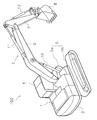
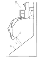
以下、本発明の実施形態について、図面を参照しながら説明する。図1は、実施形態に係る作業車両100の斜視図である。本実施形態において、作業車両100は油圧ショベルである。作業車両100は、車両本体1と、作業機2とを有する。
Hereinafter, embodiments of the present invention will be described with reference to the drawings. FIG. 1 is a perspective view of a
車両本体1は、旋回体3と走行装置5とを有する。旋回体3は、後述するエンジン及び油圧ポンプなどを収容している。旋回体3には運転室4が載置されている。走行装置5は履帯5a,5bを有しており、履帯5a,5bが回転することにより作業車両100が走行する。
The vehicle body 1 includes a turning
作業機2は、車両本体1に取り付けられている。作業機2は、ブーム6と、アーム7と、バケット8と、を有する。ブーム6の基端部は、車両本体1の前部に動作可能に取り付けられている。アーム7の基端部は、ブーム6の先端部に動作可能に取り付けられている。アーム7の先端部には、バケット8が動作可能に取り付けられている。
The
なお、バケット8は、作業具の一例である。バケット8以外の作業具がアーム7の先端部に取り付けられてもよい。
The
作業機2は、ブームシリンダ10と、アームシリンダ11と、バケットシリンダ12と、を有する。ブームシリンダ10とアームシリンダ11とバケットシリンダ12とは、それぞれ作動油によって駆動される油圧シリンダである。ブームシリンダ10はブーム6を駆動する。アームシリンダ11は、アーム7を駆動する。バケットシリンダ12は、バケット8を駆動する。
The
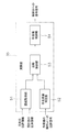
図2は、作業車両100の駆動系200と制御システム300との構成を示すブロック図である。図2に示すように、駆動系200は、エンジン21と、油圧ポンプ22,23とを備える。
FIG. 2 is a block diagram showing the configuration of
油圧ポンプ22,23は、エンジン21によって駆動され、作動油を吐出する。油圧ポンプ22,23から吐出された作動油は、ブームシリンダ10とアームシリンダ11とバケットシリンダ12とに供給される。また、作業車両100は、旋回モータ24を備える。旋回モータ24は、油圧モータであり、油圧ポンプ22,23から吐出された作動油によって駆動される。旋回モータ24は、旋回体3を旋回させる。
The hydraulic pumps 22 and 23 are driven by the
なお、図2では、2つの油圧ポンプ22,23が図示されているが、1つの油圧ポンプのみが設けられてもよい。旋回モータ24は、油圧モータに限らず、電気モータであってもよい。
In FIG. 2, two
制御システム300は、操作装置25と、コントローラ26と、制御弁27とを備える。操作装置25は、作業機2を操作するための装置である。操作装置25は、作業機2を駆動するためのオペレータによる操作を受け付け、操作量に応じた位置信号を出力する。操作装置25は、第1操作レバー28と第2操作レバー29とを有する。
The
第1操作レバー28は、前後左右の4方向に操作可能に設けられている。第1操作レバー28の4つの操作方向のうち2つが、ブーム6の上げ操作と下げ操作とに割り当てられている。第1操作レバー28の残りの2つの操作方向が、バケット8の上げ操作と下げ操作とに割り当てられている。
The
第2操作レバー29は、前後左右の4方向に操作可能に設けられている。第2操作レバー29の4つの操作方向のうち2つが、アーム7の上げ操作(アームダンプ操作)と下げ操作(アーム掘削操作)とに割り当てられている。第2操作レバー29の残りの2つの操作方向が、旋回体3の右旋回操作と左旋回操作とに割り当てられている。
The
なお、第1操作レバー28と第2操作レバー29とに割り当てられる操作内容は、上記のものに限らず、変更されてもよい。
The operation content assigned to the
操作装置25は、ブーム操作部31とバケット操作部32とを有する。ブーム操作部31は、ブーム6を操作するための第1操作レバー28の操作量(以下、「ブーム操作量」と呼ぶ)に応じた位置信号を出力する。バケット操作部32は、バケット8を操作するための第1操作レバー28の操作量(以下、「バケット操作量」と呼ぶ)に応じた位置信号を出力する。
The operation device 25 includes a
操作装置25は、アーム操作部33と旋回操作部34とを有する。アーム操作部33は、アーム7を操作するための第2操作レバー29の操作量(以下、「アーム操作量」と呼ぶ)に応じた位置信号を出力する。旋回操作部34は、旋回体3の旋回を操作するための第2操作レバー29の操作量に応じた位置信号を出力する。各操作部31−34からの位置信号は、コントローラ26に入力される。
The operation device 25 includes an
コントローラ26は、取得した情報に基づいて作業車両100を制御するようにプログラムされている。コントローラ26は、記憶部38と演算部35とを有する。記憶部38は、例えばRAM及びROMなどのメモリーと、補助記憶装置とから構成される。演算部35は、例えばCPU等の処理装置によって構成される。コントローラ26は、ブーム操作部31、アーム操作部33、バケット操作部32、及び、旋回操作部34からの位置信号を取得する。コントローラ26は、これらの位置信号に基づいて、制御弁27を制御する。
The
制御弁27は、電磁比例制御弁であり、コントローラ26からの指令信号によって制御される。制御弁27は、ブームシリンダ10、アームシリンダ11、バケットシリンダ12、及び旋回モータ24などの油圧アクチュエータと、油圧ポンプ22,23との間に配置される。制御弁27は、油圧ポンプ22,23からブームシリンダ10、アームシリンダ11、バケットシリンダ12、及び、旋回モータ24に供給される作動油の流量を制御する。
The
コントローラ26は、上述した各操作レバー28,29の操作量に応じた速度で作業機2が動作するように、制御弁27への指令信号を制御する。これにより、ブームシリンダ10、アームシリンダ11、バケットシリンダ12、及び旋回モータ24などの出力が、各操作レバー28,29の操作量に応じて、制御される。
The
なお、制御弁27は、圧力比例制御弁であってもよい。その場合、ブーム操作部31とバケット操作部32とアーム操作部33と旋回操作部34からは、各操作部材の操作量に応じたパイロット圧が出力され、制御弁27に入力される。制御弁27は、入力されたパイロット圧に応じて、ブームシリンダ10、アームシリンダ11、バケットシリンダ12、及び、旋回モータ24に供給される作動油の流量を制御する。この場合、各操作部31−34からの位置信号は、各操作部31−34から出力されるパイロット圧を示す信号であってもよい。
The
制御システム300は、第1ストロークセンサ16と第2ストロークセンサ17と第3ストロークセンサ18とを有する。第1ストロークセンサ16は、ブームシリンダ10のストローク長さ(以下、「ブームシリンダ長」という。)を検出する。第2ストロークセンサ17は、アームシリンダ11のストローク長さ(以下、「アームシリンダ長」という。)を検出する。第3ストロークセンサ18は、バケットシリンダ12のストローク長さ(以下、「バケットシリンダ長」という。)を検出する。ストロークの計測には角度センサ等を用いてもよい。
The
制御システム300は、傾斜角度センサ19を備える。傾斜角度センサ19は、旋回体3に配置される。傾斜角度センサ19は、旋回体3の車両前後方向の水平に対する角度(ピッチ角)、および車両横方向の水平に対する角度(ロール角)を検出する。
The
これらのセンサ16−19は、検出信号をコントローラ26に送る。なお、旋回角度は後述するGNSSアンテナ37の位置情報より取得してもよい。コントローラ26は、センサ16−19からの検出信号に基づいて、作業機2の姿勢を判定する。
These sensors 16-19 send detection signals to the
制御システム300は、位置検出部36を備えている。位置検出部36は、作業車両100の現在位置を検出する。位置検出部36は、GNSSアンテナ37と3次元位置センサ39とを有する。GNSSアンテナ37は、旋回体3に設けられている。GNSSアンテナ37は、RTK−GNSS(Real Time Kinematic - Global Navigation Satellite Systems、GNSSは全地球航法衛星システムをいう。)用のアンテナである。GNSSアンテナ37で受信されたGNSS電波に応じた信号が、3次元位置センサ39に入力される。
The
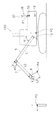
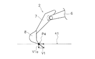
図3は、作業車両100の構成を模式的に示す側面図である。3次元位置センサ39は、グローバル座標系におけるGNSSアンテナ37の設置位置P1を検出する。グローバル座標系は、作業エリアに設置した基準位置P2を元にした3次元座標系である。図3に示すように、基準位置P2は、例えば、作業エリアに設定された基準杭の先端に位置する。コントローラ26は、位置検出部36による検出結果と作業機2の姿勢とに基づいて、グローバル座標系で見たときの作業機2の刃先P4の位置を演算する。なお、作業機2の刃先P4は、バケット8の刃先P4と表現してもよい。
FIG. 3 is a side view schematically showing the configuration of the
コントローラ26は、第1ストロークセンサ16が検出したブームシリンダ長から、ローカル座標系の垂直方向に対するブーム6の傾斜角θ1を算出する。コントローラ26は、第2ストロークセンサ17が検出したアームシリンダ長から、ブーム6に対するアーム7の傾斜角θ2を算出する。コントローラ26は、第3ストロークセンサ18が検出したバケットシリンダ長から、アーム7に対するバケット8の傾斜角θ3を算出する。
The
コントローラ26の記憶部38は、作業機データを記憶している。作業機データは、ブーム6の長さL1、アーム7の長さL2、バケット8の長さL3を含む。また、作業機データは、ローカル座標系の基準位置P3に対するブームピン13の位置情報を含む。ここでローカル座標系とは作業車両100を基準とする3次元座標系である。ローカル座標系の基準位置P3は、例えば、旋回体3の旋回中心に位置する。
The
コントローラ26は、ブーム6の傾斜角θ1、アーム7の傾斜角θ2、バケット8の傾斜角θ3、ブーム6の長さL1、アーム7の長さL2、バケット8の長さL3、及び、ブームピン13の位置情報から、ローカル座標系における刃先P4の位置を算出する。
The
また、作業機データは、ローカル座標系の基準位置P3に対するGNSSアンテナ37の設置位置P1の位置情報を含む。コントローラ26は、位置検出部36による検出結果とGNSSアンテナ37の位置情報とから、ローカル座標系における刃先P4の位置を、グローバル座標系における刃先P4の位置に変換する。これにより、コントローラ26は、グローバル座標系で見たときの刃先P4の位置情報を取得する。
Further, the work machine data includes position information of the installation position P1 of the
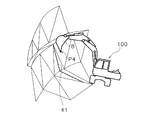
コントローラ26の記憶部38は、作業エリア内の3次元の設計地形の形状および位置を示す施工情報を記憶している。図4は、設計地形の一例を示す模式図である。図4に示すように、設計地形は、ポリゴンによってそれぞれ表現される複数の設計面41によって構成されている。複数の設計面41それぞれは、作業機2による掘削対象の目標形状を示している。なお、図4では複数の設計面41のうちの1つのみに符号41が付されており、他の設計面41の符号は省略されている。
The
コントローラ26は、設計面41を考慮に入れた作業機2の自動制御を行う。当該自動制御には、バケット8が設計面41を浸食すること防止するための作業機2の制御を含む。コントローラ26は、自動制御において、上述した施工情報と作業機2の位置情報とに基づいて作業機2を制御する。作業機2の自動制御とは、操作装置25を介したオペレータの操作指示に基づいた作業機2の動作制御とは別個に、コントローラ26が独自に行う作業機2の動作制御を意味する。作業機2の自動制御には、或る作業を実行する上での完全自動制御、及び半自動制御が含まれる。以下、コントローラ26によって実行される作業機2の自動制御について詳細に説明する。
The
図5は、コントローラ26の構成を示すブロック図である。コントローラ26の演算部35は、距離取得部51と、作業局面判定部52と、自動制御部53と、作業機制御部54とを有する。距離取得部51は、図6に示すように、作業機2と設計面41との間の距離d1を取得する。詳細には、距離取得部51は、上述した作業機2の刃先P4の位置情報と、設計面41の位置情報とに基づいて、作業機2の刃先P4と設計面41との間の距離d1を算出する。
FIG. 5 is a block diagram showing the configuration of the
作業局面判定部52は、作業機2による作業局面を判定する。作業局面判定部52は、上述したブーム操作部31、アーム操作部33、バケット操作部32からの位置信号に基づいて、作業機2による作業局面が、掘削、或いは整地などの作業であるのかを判定する。例えば、作業局面判定部52は、ブーム操作、又は、バケット操作が行われているが、アーム操作が行われていない場合に、作業局面が、掘削作業であると判定する。作業局面判定部52は、アーム操作が行われている場合に、作業局面が、整地作業であると判定する。
The work
作業局面が掘削作業であるときには、自動制御部53は、速度制限制御を行う。自動制御部53は、速度制限制御において、作業機2と設計面41との間の距離d1が小さくなるほど作業機2の速度を制限する。すなわち、自動制御部53は、速度制限制御において、作業機2と設計面41との間の距離d1が小さくなるほど作業機2の速度の上限を小さくする。これにより、掘削時に、作業機2が設計面41を超えて掘削してしまうことを抑えることができる。
When the work phase is excavation work, the
作業局面が整地作業であるときには、自動制御部53は、整地制御を実行する。整地制御は、作業機2が設計面41に沿って移動するように作業機2を制御する制御である。図7に示すように、作業機2の刃先P4が設計面41に近づくように速度V1で移動している場合、自動制御部53は、速度V1の設計面41に垂直な速度成分V1aを算出する。自動制御部53は、垂直な速度成分V1aを相殺するように、ブーム6を上昇させる速度を決定する。これにより、整地制御によって、刃先P4が設計面41に沿って移動するように、作業機2が制御される。
When the work phase is leveling work, the
作業機制御部54は、上述した制御弁27への指令信号を出力することで、作業機2を制御する。作業機制御部54は、作業機2の操作量に応じて、制御弁27への指令信号の出力値を決定する。また、作業機制御部54は、自動制御の実行中には、自動制御部53が決定した作業機2の速度に基づいて、制御弁27への指令信号の出力値を決定する。
The work
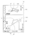
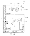
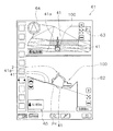
図2に示すように、制御システム300は、表示部40を備えている。表示部40は、例えばモニタであり、作業車両100に関する情報を表示する。コントローラ26は、設計地形や上述した各種のセンサからの検出結果などに基づいて、案内画面を表示部40に表示させる。図8は、案内画面61の一例を示す図である。図8に示すように、案内画面61は、設計面41と作業機2との位置関係を示している。
As shown in FIG. 2, the
詳細には、案内画面61は、第1案内画面62と第2案内画面63とを含む。第1案内画面62は、設計面41と作業機2とを側面図で示している。第2案内画面63は、設計面41と作業機2とを斜視図で示している。案内画面61は、作業機2と設計面41との間の距離を示す距離表示65を含む。なお、第1案内画面62と第2案内画面63との一方が省略されてもよい。
Specifically, the
図2に示すように、制御システム300は、入力部42を備えている。入力部42は、上述した自動制御の設定を入力するための装置である。オペレータは、入力部42を操作することによって、自動制御の設定を変更することができる。本実施形態において、入力部42は、表示部40と一体的に設けられたタッチパネル装置である。ただし、入力部42は、表示部40と別体に設けられてもよい。
As shown in FIG. 2, the
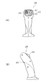
次に、第1操作レバー28及び第2操作レバー29による自動制御の操作について詳細に説明する。図9(A)は、第1操作レバー28の正面図である。図9(B)は、第1操作レバー28の側面図である。図9(A)及び図9(B)に示すように、第1操作レバー28には、複数の操作部材A1,A2,A3,A4,A5が設けられている。操作部材A1,A2,A3,A4は、第1操作レバー28の正面に設けられている。操作部材A1,A2,A3,A4は、第1操作レバー28の上部に設けられている。操作部材A5は、第1操作レバー28の背面に設けられている。
Next, the automatic control operation by the
操作部材A1,A2,A3は、押しボタン式のスイッチである。操作部材A1,A2,A3の押圧のON/OFFを示す操作信号が、操作部材A1,A2,A3からコントローラ26に入力される。操作部材A4は、スライド式、或いは回転式のスイッチである。操作部材A4の操作位置に応じた操作信号が操作部材A4からコントローラ26に入力される。操作部材A5はトリガー式のスイッチである。操作部材A5の押圧のON/OFFを示す操作信号が、操作部材A5からコントローラ26に入力される。
The operation members A1, A2 and A3 are push button type switches. An operation signal indicating ON / OFF of pressing of the operation members A1, A2, and A3 is input to the
図10(A)は、第2操作レバー29の正面図である。図10(B)は、第2操作レバー29の側面図である。図10(A)及び図10(B)に示すように、第2操作レバー29には、複数の操作部材B1,B2,B3,B4,B5が設けられている。操作部材B1,B2,B3,B4は、第2操作レバー29の正面に設けられている。操作部材B1,B2,B3,B4は、第2操作レバー29の上部に設けられている。操作部材B5は、第2操作レバー29の背面に設けられている。
FIG. 10A is a front view of the
操作部材B1,B2,B3は、押しボタン式のスイッチである。操作部材B1,B2,B3の押圧のON/OFFを示す操作信号が、操作部材B1,B2,B3からコントローラ26に入力される。操作部材B4は、スライド式、或いは回転式のスイッチである。操作部材B4の操作位置に応じた操作信号が操作部材B4からコントローラ26に入力される。操作部材B5はトリガー式のスイッチである。操作部材B5の押圧のON/OFFを示す操作信号が、操作部材B5からコントローラ26に入力される。
The operation members B1, B2, and B3 are push button type switches. An operation signal indicating ON / OFF of pressing of the operation members B1, B2, and B3 is input to the
これらの操作部材A1−A5,B1−B5の一部には、自動制御の機能が割り当てられている。本実施形態においては、操作部材A2,B2,A5に、自動制御の機能が割り当てられている。 An automatic control function is assigned to a part of these operation members A1-A5 and B1-B5. In the present embodiment, automatic control functions are assigned to the operation members A2, B2, and A5.
なお、操作部材A2,B2,A5以外の操作部材には、作業機2に関する操作、及び、車両本体1に関する操作が割り当てられている。作業機2に関する操作は、例えば、バケット8に代えてブレーカ等の作業具が作業機2に設けられた場合の作業具の操作である。車両本体1に関する操作は、例えばエンジン出力を増大させる操作、或いは、警笛を鳴らす操作などである。
Note that operations related to the work implement 2 and operations related to the vehicle main body 1 are assigned to the operation members other than the operation members A2, B2, and A5. The operation related to the work implement 2 is, for example, an operation of the work implement when a work implement such as a breaker is provided in the work implement 2 instead of the
詳細には、操作部材A2には、設計面41の位置を上昇させる機能が割り当てられている。操作部材A2が操作されることにより、設計面41の位置が上方に変更される。操作部材A2の一回の操作ごとに、設計面41の位置が、所定距離、上方に変更される。
Specifically, a function for raising the position of the
図11は、操作部材A2が1回、押されることによって、案内画面61において、設計面41が、当初の位置(図8参照)から上方に所定距離、移動した状態を示している。図12は、操作部材A2がさらにもう一回、押されることによって、案内画面61において、設計面41がさらに上方に所定距離、移動した状態を示している。
FIG. 11 shows a state in which the
操作部材B2には、設計面41の位置を下降させる機能が割り当てられている。操作部材B2が操作されることにより、設計面41の位置が下方に変更される。操作部材B2の一回の操作ごとに、設計面41の位置が、所定距離、下方に変更される。図13は、操作部材B2が一回、押されることによって、案内画面61において、設計面41が、当初の位置(図8参照)から下方に所定距離、移動した状態を示している。図14は、操作部材B2がさらにもう一回、押されることによって、案内画面61において、設計面41がさらに下方に所定距離、移動した状態を示している。
A function for lowering the position of the
以上のように、操作部材A2,B2が操作されることにより、案内画面61における設計面41の位置が上下に変更される。そして、変更された設計面41の位置に基づいて上述した自動制御が実行される。なお、上述した所定距離は入力部42の操作によって変更可能であってもよい。或いは、上述した所定距離は固定値であってもよい。
As described above, when the operation members A2 and B2 are operated, the position of the
操作部材A5には、自動制御の有効化/無効化の機能が割り当てられている。操作部材A5が操作されるごとに、自動制御の有効化と無効化とが交互に切り換えられる。自動制御の有効化は、自動制御が許可されることを意味している。自動制御の無効化は、自動制御が許可されず、作業機2の操作モードが、作業機2を手動で操作するマニュアルモードとなることを意味している。
A function for enabling / disabling automatic control is assigned to the operation member A5. Each time the operating member A5 is operated, the automatic control is alternately switched between valid and invalid. Enabling automatic control means that automatic control is permitted. Disabling automatic control means that automatic control is not permitted, and the operation mode of the
上述したように、オペレータは、操作部材A2,B2,A5を操作することによって、操作部材A2,B2,A5のそれぞれに割り当てられている自動制御の機能を実行させることができる。ただし、コントローラ26は、実行条件が満たされていることを条件として、操作部材A2,B2,A5に割り当てられた自動制御の機能を実行する。
As described above, the operator can execute the automatic control function assigned to each of the operation members A2, B2, and A5 by operating the operation members A2, B2, and A5. However, the
実行条件は、作業機2を動作させるためのオペレータによる操作レバーの操作がないことである。本実施形態において、実行条件は、第1操作レバー28が中立位置にあり、且つ、第2操作レバー29が中立位置にあることである。従って、第1操作レバー28と第2操作レバー29とが共に中立位置にあるときに、操作部材A2が操作されることで、設計面41の位置が上方に移動する。第1操作レバー28と第2操作レバー29とが中立位置にあるときに、操作部材B2が操作されることで、設計面41の位置が下方に移動する。第1操作レバー28と第2操作レバー29との少なくとも一方が中立位置と異なる位置に操作されているときには、操作部材A2、B2が操作されても、設計面41の位置は変更されない。
The execution condition is that there is no operation of the operation lever by the operator for operating the
また、第1操作レバー28と第2操作レバー29とが中立位置にあるときに、操作部材A5が操作されることで、自動制御の有効化/無効化が切り換えられる。第1操作レバー28と第2操作レバー29との少なくとも一方が中立位置と異なる位置に操作されているときには、操作部材A5が操作されても、自動制御の有効化/無効化は切り換えられない。
Further, when the
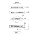
図15は、上述した操作部材A2,B2,A5の操作時の処理を示すフローチャートである。ここでは一例として、操作部材A2が操作された場合について説明する。 FIG. 15 is a flowchart showing processing at the time of operation of the operation members A2, B2, and A5 described above. Here, as an example, a case where the operation member A2 is operated will be described.
図15に示すように、ステップS1では、操作部材A2の操作が検出される。ここでは、コントローラ26が、操作部材A2からの操作信号を受信することで、操作部材A2の操作を検出する。
As shown in FIG. 15, in step S1, the operation of the operation member A2 is detected. Here, the
ステップS2では、操作レバー28,29の位置が検出される。ここでは、コントローラ26が、第1操作レバー28の位置を示す位置信号を操作装置25から受信することで、第1操作レバー28の位置を検出する。また、コントローラ26が、第2操作レバー29の位置を示す位置信号を操作装置25から受信することで、第2操作レバー29の位置を検出する。
In step S2, the positions of the operation levers 28 and 29 are detected. Here, the
ステップS3では、実行条件が満たされているか否かが判定される。ここでは、コントローラ26は、第1操作レバー28が中立位置にあり、且つ、第2操作レバー29が中立位置にあるか否かを判定する。第1操作レバー28と第2操作レバー29との両方が中立位置にある場合には、コントローラ26は、実行条件が満たされていると判定する。第1操作レバー28と第2操作レバー29との少なくとも一方が中立位置と異なる位置にある場合には、コントローラ26は、実行条件が満たされていないと判定する。
In step S3, it is determined whether or not the execution condition is satisfied. Here, the
実行条件が満たされているときには、ステップS4において、操作部材A2の機能が実行される。ここでは、コントローラ26は、設計面41の位置を上方に変更する。実行条件が満たされていないときには、操作部材A2が操作されていても、操作部材A2の機能は実行されない。すなわち、実行条件が満たされていないときには、操作部材A2が操作されていても、設計面41の位置は変更されない。
When the execution condition is satisfied, the function of the operation member A2 is executed in step S4. Here, the
なお、操作部材B2が操作された場合には、ステップS4において、設計面41の位置が下方に変更される。操作部材A5が操作された場合には、ステップS4において、自動制御の有効化と無効化とが切り換えられる。なお、操作部材A2,B2,A5に割り当てられている機能は、入力部42によっても操作可能である。
If the operation member B2 is operated, the position of the
以上説明した本実施形態に係る作業車両100の制御システム300では、操作部材A2、A5が第1操作レバー28に設けられている。そのため、オペレータは、第1操作レバー28を握ったまま、操作部材A2,A5を操作することができる。これにより、操作部材A2,A5に割り当てられた自動制御の機能を容易に操作することができる。同様に、操作部材B2が第2操作レバー29に設けられている。そのため、オペレータは、第2操作レバー29を握ったまま、操作部材B2を操作することができる。これにより、操作部材B2に割り当てられた自動制御の機能を容易に操作することができる。
In the
具体的には、オペレータは、第1操作レバー28と第2操作レバー29とを握ったまま、操作部材A2,B2を操作することで、設計面41の位置を上下に変更することができる。また、オペレータは、第1操作レバー28を握ったまま、操作部材A5を操作することで、自動制御の有効化と無効化とを切り換えることができる。
Specifically, the operator can change the position of the
また、第1操作レバー28と第2操作レバー29との少なくとも一方が中立位置と異なる位置にあるときには、操作部材A2,B2,A5が操作されても、各操作部材A2,B2,A5に割り当てられた自動制御の機能は実行されない。そのため、操作部材A2,B2,A5の操作中に第1操作レバー28又は第2操作レバー29が動いたとしても、各操作部材A2,B2,A5に割り当てられた自動制御の機能の実行と、第1操作レバー28又は第2操作レバー29による作業機2の動作とが同時に行われることを防止することができる。それにより、誤操作による意図しない作業機2の動作を防止することができ、自動制御による品質の良い施工を行うことができる。
Further, when at least one of the
以上、本発明の一実施形態について説明したが、本発明は上記実施形態に限定されるものではなく、発明の要旨を逸脱しない範囲で種々の変更が可能である。 As mentioned above, although one Embodiment of this invention was described, this invention is not limited to the said embodiment, A various change is possible in the range which does not deviate from the summary of invention.
作業車両100は、油圧ショベルに限らず、ブルドーザー、或いはホイールローダなどの作業機を有する車両であればよい。
The
作業車両100は、遠隔操作可能であってもよい。すなわち、コントローラ26が、作業車両100の外部に配置されるリモートコントローラと、作業車両100の内部に配置される車載コントローラとに分けられて、互いに通信可能に構成されてもよい。
作業機2の刃先P4の位置の決定方法は、上記の実施形態のものに限られず、変更されてもよい。例えば、作業機2の刃先P4に位置検出部36が配置されてもよい。
The determination method of the position of the blade edge | tip P4 of the working
作業機2と設計面41との間の距離d1の検出方法は、上記の実施形態のものに限られず、変更されてもよい。例えば、光学式、超音波式、或いはレーザー光線式の距離測定装置により、作業機2と設計面41との間の距離d1が検出されてもよい。
The detection method of the distance d1 between the
各操作部材A2,B2,A5の操作に応じた自動制御の機能の実行条件が互いに異なっていてもよい。例えば、第1操作レバー28の操作部材A2,A5が操作されたときの実行条件(第1の実行条件)は、第1操作レバー28が中立位置にあることを含み、第2操作レバー29が中立位置にあることを含まなくてもよい。また、第2操作レバー29の操作部材B2が操作されたときの実行条件(第2の実行条件)は、第2操作レバー29が中立位置にあることを含み、第1操作レバー28が中立位置にあることを含まなくてもよい。
The execution conditions of the automatic control function according to the operation of each operation member A2, B2, A5 may be different from each other. For example, the execution condition (first execution condition) when the operation members A2 and A5 of the
上記の実施形態では、設計面41の位置を上方に変更するための操作部材A2(第1操作部材)と、設計面41の位置を下方に変更するための操作部材B2(第2操作部材)とが、それぞれ別の操作レバー28,29に設けられている。しかし、操作部材A2と操作部材B2とが共通の操作レバーに設けられてもよい。或いは、操作部材A4、又は、操作部材B4のように上下に操作可能な操作部材に、設計面41の位置を上下に変更する機能が割り当てられてもよい。
In the above embodiment, the operation member A2 (first operation member) for changing the position of the
第1操作レバー28及び第2操作レバー29の構造が変更されてもよい。第1操作レバー28に設けられる操作部材、及び、第2操作レバー29に設けられる操作部材の数、配置、或いは、形状が変更されてもよい。自動制御の機能が割り当てられる操作部材は、操作部材A2,B2,A5に限らず、他の操作部材であってもよい。
The structures of the
操作部材に割り当てられる自動制御の機能は、設計面41の位置の変更と、自動制御の有効化/無効化の切換に限らず、他の機能であってもよい。自動制御に含まれる機能のうち使用頻度の高いものが、操作部材に割り当てられることが好ましい。例えば、図16に示すように、自動制御は、整地制御において、設計面41に対するバケット8の角度Anを一定に保持する角度保持制御を含んでもよい。角度保持制御の有効化/無効化の切換が、操作部材に割り当てられてもよい。
The function of the automatic control assigned to the operation member is not limited to the change of the position of the
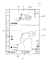
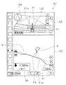
複数の設計面41のうち特定の設計面を選択する機能が、操作部材に割り当てられてもよい。例えば、図17に示すように、刃先P4の直下に位置する設計面41aを選択する機能が操作部材に割り当てられてもよい。選択された設計面41aに基づいて、上述した自動制御が実行されてもよい。或いは、選択された設計面41aが、他の設計面41と異なる態様(例えば異なる色)で示されてもよい。或いは、選択された設計面41aに対して作業車両100が正対しているのか否かが、案内画面61において示されてもよい。図17においては、選択された設計面41aに対して作業車両100が正対しているのか否かが、案内画面61においてコンパス型のアイコン64で示されている。
A function of selecting a specific design surface among the plurality of design surfaces 41 may be assigned to the operation member. For example, as shown in FIG. 17, the function of selecting the
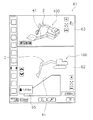
案内画面61における表示スケールを変更する機能が、操作部材に割り当てられてもよい。例えば、図17に示すような概略表示の案内画面61と、図18に示す詳細表示の案内画面61’とを切り換える機能が、操作部材に割り当てられてもよい。図18に示す詳細表示では、図17に示す概略表示よりも、設計面41,41aが大きく表示されてもよい。また、図17に示す概略表示では作業車両100全体が案内画面61に表示されてもよい。これに対して、図18に示す詳細表示では、バケット8のみが、概略表示よりも大きなスケールで案内画面61’に表示されてもよい。
The function of changing the display scale on the
操作部材の操作に応じた自動制御の機能の実行条件は、当該操作部材以外の操作部材が操作されていることをさらに含んでもよい。例えば、第1操作レバー28が中立であり、且つ、操作部材A4が操作された状態のまま、操作部材A2が操作されることで、自動制御の機能が実行されてもよい。或いは、第2操作レバー29が中立であり、且つ、操作部材B4が操作された状態のまま、操作部材B2が操作されることで、自動制御の機能が実行されてもよい。
The execution condition of the automatic control function according to the operation of the operation member may further include that an operation member other than the operation member is operated. For example, the automatic control function may be executed by operating the operation member A2 while the
或いは、第1操作レバー28が中立であり、且つ、操作部材A4が操作されていない状態で操作部材A2が操作されることで、自動制御の所定の機能(第1の機能)が実行されてもよい。また、第2操作レバー29が中立であり、且つ、操作部材A4が操作された状態のまま、操作部材A2が操作されることで、第1の機能と異なる自動制御の所定の機能(第3の機能)が実行されてもよい。
Alternatively, a predetermined function (first function) of automatic control is executed by operating the operation member A2 in a state where the
例えば、第1の機能は、上述した設計面41の位置を上方、又は、下方に変更する機能であってもよい。第3の機能は、設計面41を選択する機能であってもよい。或いは、第3の機能は、案内画面61の表示スケールを変更する機能であってもよい。第1の機能、及び、第3の機能は、上述した機能と異なる機能であってもよい。
For example, the first function may be a function of changing the position of the
上述した実行条件に含まれる条件は変更されてもよい。或いは、実行条件に含まれる条件に、上述した条件と異なる条件が追加されてもよい。実行条件は、操作レバーが中立位置にあることに限らず、オペレータによる操作レバーの操作がないことを示す他の条件を含んでもよい。 Conditions included in the execution conditions described above may be changed. Alternatively, a condition different from the above-described condition may be added to the condition included in the execution condition. The execution condition is not limited to the operation lever being in the neutral position, and may include other conditions indicating that the operation lever is not operated by the operator.
本発明よれば、自動制御の機能を容易に操作することができると共に、誤操作による意図しない作業機の動作を防止することができ、自動制御による品質の良い施工を行うことができる。 According to the present invention, an automatic control function can be easily operated, an unintended operation of the work machine due to an erroneous operation can be prevented, and high-quality construction can be performed by automatic control.
2 作業機
28 第1操作レバー
29 第2操作レバー
A2 第1操作部材
B2 第2操作部材
A4 第3操作部材
26 コントローラ
100 作業車両
300 制御システム
2 Work implement 28
Claims (13)
前記作業機の第1操作レバーと、
前記第1操作レバーに設けられた第1操作部材と、
前記作業機の自動制御を行うコントローラと、
を備え、
前記コントローラは、前記第1操作レバーが中立位置にあることを含む実行条件が満たされているときに、前記第1操作部材の操作に応じて、前記第1操作部材に割り当てられた前記自動制御の機能を実行する、
作業車両の制御システム。 A control system for a work vehicle having a work machine,
A first operating lever of the working machine;
A first operating member provided on the first operating lever;
A controller that performs automatic control of the working machine;
With
The controller controls the automatic control assigned to the first operation member in accordance with an operation of the first operation member when an execution condition including that the first operation lever is in a neutral position is satisfied. Perform the functions of
Work vehicle control system.
請求項1に記載の作業車両の制御システム。 In the automatic control, the controller controls the working machine based on a design terrain representing a target shape of a work target.
The work vehicle control system according to claim 1.
請求項2に記載の作業車両の制御システム。 The controller changes the position of the design terrain according to the operation of the first operation member when the execution condition is satisfied,
The work vehicle control system according to claim 2.
前記自動制御の前記第1の機能と異なる第2の機能を実行させるための第2操作部材をさらに備える、
請求項1から3のいずれかに記載の作業車両の制御システム。 The first operation member is an operation member for executing the first function of the automatic control,
A second operating member for executing a second function different from the first function of the automatic control;
The work vehicle control system according to claim 1.
請求項4に記載の作業車両の制御システム。 The controller enables or disables the automatic control according to an operation of the second operation member when the execution condition is satisfied;
The work vehicle control system according to claim 4.
前記コントローラは、前記実行条件が満たされているときに、前記第1操作部材の操作に応じて前記第1の機能を実行し、前記実行条件が満たされているときに、前記第2操作部材の操作に応じて前記第2の機能を実行する、
請求項4に記載の作業車両の制御システム。 The first operating member and the second operating member are both provided on the first operating lever,
The controller executes the first function according to an operation of the first operation member when the execution condition is satisfied, and the second operation member when the execution condition is satisfied. The second function is executed in response to the operation of
The work vehicle control system according to claim 4.
請求項4に記載の作業車両の制御システム。 A second operating lever provided with the second operating member;
The work vehicle control system according to claim 4.
請求項7に記載の作業車両の制御システム。 The controller executes the first function in response to an operation of the first operation member when a first execution condition including that the first operation lever is in a neutral position is satisfied, Executing the second function in response to an operation of the second operation member when a second execution condition including that the two operation levers are in a neutral position is satisfied,
The work vehicle control system according to claim 7.
前記コントローラは、前記実行条件が満たされているときに前記第1操作部材の操作に応じて前記第1の機能を実行し、前記実行条件が満たされたときに前記第2操作部材の操作に応じて前記第2の機能を実行する、
請求項7に記載の作業車両の制御システム。 The execution condition includes that the first operation lever is in a neutral position, and that the second operation lever is in a neutral position,
The controller executes the first function according to an operation of the first operation member when the execution condition is satisfied, and operates the second operation member when the execution condition is satisfied. Performing the second function in response,
The work vehicle control system according to claim 7.
前記実行条件は、前記第3操作部材が操作されていることをさらに含む、
請求項1から9のいずれかに記載の作業車両の制御システム。 A third operation member provided on the first operation lever;
The execution condition further includes that the third operation member is operated,
The work vehicle control system according to claim 1.
請求項10に記載の作業車両の制御システム。 The controller is configured such that when a first execution condition including that the first operating lever is in a neutral position and the third operating member is not operated is satisfied, The first function of the automatic control is executed according to an operation, and a third execution condition including that the first operation lever is in a neutral position and that the third operation member is operated is satisfied. A third function different from the first function is executed according to an operation of the first operating member.
The work vehicle control system according to claim 10.
前記作業機の第1操作レバーの位置を示す位置信号を受信するステップと、
前記第1操作レバーに設けられた第1操作部材の操作を示す操作信号を受信するステップと、
オペレータによる前記第1操作レバーの操作がないことを含む実行条件が満たされているか否かを判定するステップと、
前記実行条件が満たされているときに、前記第1操作部材の操作に応じて前記第1操作部材に割り当てられた前記作業機の自動制御の機能を実行するステップと、
を備える作業車両の制御方法。 A method for controlling a work vehicle having a work machine,
Receiving a position signal indicating the position of the first operating lever of the working machine;
Receiving an operation signal indicating an operation of a first operation member provided on the first operation lever;
Determining whether an execution condition including no operation of the first operating lever by an operator is satisfied;
Executing the automatic control function of the work implement assigned to the first operation member in accordance with the operation of the first operation member when the execution condition is satisfied;
A method for controlling a work vehicle.
前記作業機の第1操作レバーと、
前記第1操作レバーに設けられたた第1操作部材と、
前記作業機の自動制御を行うコントローラと、
を備え、
前記コントローラは、前記第1操作レバーが中立位置にあることを含む実行条件が満たされているときに、前記第1操作部材の操作に応じて前記第1操作部材に割り当てられた前記自動制御の機能を実行する、
作業車両。 A working machine,
A first operating lever of the working machine;
A first operating member provided on the first operating lever;
A controller that performs automatic control of the working machine;
With
The controller is configured to perform the automatic control assigned to the first operation member in response to an operation of the first operation member when an execution condition including that the first operation lever is in a neutral position is satisfied. Perform function,
Work vehicle.
Priority Applications (1)
| Application Number | Priority Date | Filing Date | Title |
|---|---|---|---|
| JP2016255389A JP2017186875A (en) | 2016-12-28 | 2016-12-28 | Control system of work vehicle, control method, and work vehicle |
Applications Claiming Priority (1)
| Application Number | Priority Date | Filing Date | Title |
|---|---|---|---|
| JP2016255389A JP2017186875A (en) | 2016-12-28 | 2016-12-28 | Control system of work vehicle, control method, and work vehicle |
Related Parent Applications (1)
| Application Number | Title | Priority Date | Filing Date |
|---|---|---|---|
| JP2016535074A Division JP6072993B1 (en) | 2016-04-08 | 2016-04-08 | Work vehicle control system, control method, and work vehicle |
Publications (2)
| Publication Number | Publication Date |
|---|---|
| JP2017186875A true JP2017186875A (en) | 2017-10-12 |
| JP2017186875A5 JP2017186875A5 (en) | 2019-07-18 |
Family
ID=60044636
Family Applications (1)
| Application Number | Title | Priority Date | Filing Date |
|---|---|---|---|
| JP2016255389A Pending JP2017186875A (en) | 2016-12-28 | 2016-12-28 | Control system of work vehicle, control method, and work vehicle |
Country Status (1)
| Country | Link |
|---|---|
| JP (1) | JP2017186875A (en) |
Cited By (4)
| Publication number | Priority date | Publication date | Assignee | Title |
|---|---|---|---|---|
| JP2019124049A (en) * | 2018-01-16 | 2019-07-25 | 住友建機株式会社 | Shovel |
| WO2019175917A1 (en) * | 2018-03-12 | 2019-09-19 | 日立建機株式会社 | Work machine |
| JP2020204265A (en) * | 2020-10-02 | 2020-12-24 | 日立建機株式会社 | Hydraulic shovel |
| JP7050981B1 (en) | 2021-03-09 | 2022-04-08 | 日立建機株式会社 | Work machine |
-
2016
- 2016-12-28 JP JP2016255389A patent/JP2017186875A/en active Pending
Cited By (11)
| Publication number | Priority date | Publication date | Assignee | Title |
|---|---|---|---|---|
| JP2019124049A (en) * | 2018-01-16 | 2019-07-25 | 住友建機株式会社 | Shovel |
| JP7062445B2 (en) | 2018-01-16 | 2022-05-06 | 住友建機株式会社 | Excavator |
| WO2019175917A1 (en) * | 2018-03-12 | 2019-09-19 | 日立建機株式会社 | Work machine |
| CN110799708A (en) * | 2018-03-12 | 2020-02-14 | 日立建机株式会社 | Working machine |
| JPWO2019175917A1 (en) * | 2018-03-12 | 2020-04-16 | 日立建機株式会社 | Work machine |
| US11149411B2 (en) | 2018-03-12 | 2021-10-19 | Hitachi Construction Machinery Co., Ltd. | Work machine |
| CN110799708B (en) * | 2018-03-12 | 2021-12-31 | 日立建机株式会社 | Working machine |
| JP2020204265A (en) * | 2020-10-02 | 2020-12-24 | 日立建機株式会社 | Hydraulic shovel |
| JP7050981B1 (en) | 2021-03-09 | 2022-04-08 | 日立建機株式会社 | Work machine |
| WO2022190725A1 (en) * | 2021-03-09 | 2022-09-15 | 日立建機株式会社 | Work machine |
| JP2022138029A (en) * | 2021-03-09 | 2022-09-22 | 日立建機株式会社 | Work machine |
Similar Documents
| Publication | Publication Date | Title |
|---|---|---|
| JP6072993B1 (en) | Work vehicle control system, control method, and work vehicle | |
| JP6709880B2 (en) | Work machine | |
| JP5706050B1 (en) | Work vehicle | |
| KR101815268B1 (en) | Construction machinery display system and control method for same | |
| JP6062115B1 (en) | Work vehicle control system, control method, and work vehicle | |
| KR101654113B1 (en) | Excavator display system and method for controlling same | |
| JP5706051B1 (en) | Work vehicle | |
| KR101812127B1 (en) | Control system for work vehicle, control method, and work vehicle | |
| JP5921692B1 (en) | Excavator control system and excavator | |
| WO2015025989A1 (en) | Utility vehicle | |
| KR20150022922A (en) | Display system for excavation machine, excavation machine, and computer program for displaying excavation machine | |
| US11414839B2 (en) | Display control device and method for generating target line or control line of work machine | |
| KR102154581B1 (en) | Working machine | |
| WO2019175917A1 (en) | Work machine | |
| JP5364741B2 (en) | Hydraulic excavator position guidance system and method for controlling position guidance system | |
| KR102388111B1 (en) | working machine | |
| JP2017186875A (en) | Control system of work vehicle, control method, and work vehicle | |
| JP2017186875A5 (en) | ||
| JP6823036B2 (en) | Display system for construction machinery and its control method | |
| JP2017166308A (en) | Control system and control method for working vehicle, and working vehicle | |
| JP7168697B2 (en) | DISPLAY SYSTEM FOR CONSTRUCTION MACHINE AND CONTROL METHOD THEREOF | |
| JP2020204265A (en) | Hydraulic shovel | |
| KR20210122295A (en) | working machine | |
| JP2021050522A (en) | Work machine | |
| JP2021004539A (en) | Work machine |
Legal Events
| Date | Code | Title | Description |
|---|---|---|---|
| A621 | Written request for application examination |
Free format text: JAPANESE INTERMEDIATE CODE: A621 Effective date: 20190404 |
|
| A521 | Written amendment |
Free format text: JAPANESE INTERMEDIATE CODE: A523 Effective date: 20190611 |
|
| A131 | Notification of reasons for refusal |
Free format text: JAPANESE INTERMEDIATE CODE: A131 Effective date: 20200707 |
|
| A02 | Decision of refusal |
Free format text: JAPANESE INTERMEDIATE CODE: A02 Effective date: 20210105 |