EP3903109B1 - Method of operating and diagnosing faults in a laboratory instrument - Google Patents
Method of operating and diagnosing faults in a laboratory instrument Download PDFInfo
- Publication number
- EP3903109B1 EP3903109B1 EP19903480.2A EP19903480A EP3903109B1 EP 3903109 B1 EP3903109 B1 EP 3903109B1 EP 19903480 A EP19903480 A EP 19903480A EP 3903109 B1 EP3903109 B1 EP 3903109B1
- Authority
- EP
- European Patent Office
- Prior art keywords
- vessels
- vessel
- reagent
- alp
- wash buffer
- Prior art date
- Legal status (The legal status is an assumption and is not a legal conclusion. Google has not performed a legal analysis and makes no representation as to the accuracy of the status listed.)
- Active
Links
Images


Classifications
-
- G—PHYSICS
- G01—MEASURING; TESTING
- G01N—INVESTIGATING OR ANALYSING MATERIALS BY DETERMINING THEIR CHEMICAL OR PHYSICAL PROPERTIES
- G01N35/00—Automatic analysis not limited to methods or materials provided for in any single one of groups G01N1/00 - G01N33/00; Handling materials therefor
- G01N35/00584—Control arrangements for automatic analysers
- G01N35/00594—Quality control, including calibration or testing of components of the analyser
- G01N35/00613—Quality control
- G01N35/00623—Quality control of instruments
-
- G—PHYSICS
- G01—MEASURING; TESTING
- G01N—INVESTIGATING OR ANALYSING MATERIALS BY DETERMINING THEIR CHEMICAL OR PHYSICAL PROPERTIES
- G01N35/00—Automatic analysis not limited to methods or materials provided for in any single one of groups G01N1/00 - G01N33/00; Handling materials therefor
- G01N35/00584—Control arrangements for automatic analysers
-
- G—PHYSICS
- G01—MEASURING; TESTING
- G01N—INVESTIGATING OR ANALYSING MATERIALS BY DETERMINING THEIR CHEMICAL OR PHYSICAL PROPERTIES
- G01N35/00—Automatic analysis not limited to methods or materials provided for in any single one of groups G01N1/00 - G01N33/00; Handling materials therefor
- G01N35/00584—Control arrangements for automatic analysers
- G01N35/00594—Quality control, including calibration or testing of components of the analyser
-
- G—PHYSICS
- G01—MEASURING; TESTING
- G01N—INVESTIGATING OR ANALYSING MATERIALS BY DETERMINING THEIR CHEMICAL OR PHYSICAL PROPERTIES
- G01N35/00—Automatic analysis not limited to methods or materials provided for in any single one of groups G01N1/00 - G01N33/00; Handling materials therefor
- G01N35/00584—Control arrangements for automatic analysers
- G01N35/00594—Quality control, including calibration or testing of components of the analyser
- G01N35/00693—Calibration
-
- G—PHYSICS
- G01—MEASURING; TESTING
- G01N—INVESTIGATING OR ANALYSING MATERIALS BY DETERMINING THEIR CHEMICAL OR PHYSICAL PROPERTIES
- G01N35/00—Automatic analysis not limited to methods or materials provided for in any single one of groups G01N1/00 - G01N33/00; Handling materials therefor
- G01N35/00584—Control arrangements for automatic analysers
- G01N35/00594—Quality control, including calibration or testing of components of the analyser
- G01N35/00712—Automatic status testing, e.g. at start-up or periodic
-
- G—PHYSICS
- G01—MEASURING; TESTING
- G01N—INVESTIGATING OR ANALYSING MATERIALS BY DETERMINING THEIR CHEMICAL OR PHYSICAL PROPERTIES
- G01N35/00—Automatic analysis not limited to methods or materials provided for in any single one of groups G01N1/00 - G01N33/00; Handling materials therefor
- G01N35/0098—Automatic analysis not limited to methods or materials provided for in any single one of groups G01N1/00 - G01N33/00; Handling materials therefor involving analyte bound to insoluble magnetic carrier, e.g. using magnetic separation
-
- G—PHYSICS
- G01—MEASURING; TESTING
- G01N—INVESTIGATING OR ANALYSING MATERIALS BY DETERMINING THEIR CHEMICAL OR PHYSICAL PROPERTIES
- G01N35/00—Automatic analysis not limited to methods or materials provided for in any single one of groups G01N1/00 - G01N33/00; Handling materials therefor
- G01N35/10—Devices for transferring samples or any liquids to, in, or from, the analysis apparatus, e.g. suction devices, injection devices
- G01N35/1009—Characterised by arrangements for controlling the aspiration or dispense of liquids
- G01N35/1016—Control of the volume dispensed or introduced
-
- B—PERFORMING OPERATIONS; TRANSPORTING
- B03—SEPARATION OF SOLID MATERIALS USING LIQUIDS OR USING PNEUMATIC TABLES OR JIGS; MAGNETIC OR ELECTROSTATIC SEPARATION OF SOLID MATERIALS FROM SOLID MATERIALS OR FLUIDS; SEPARATION BY HIGH-VOLTAGE ELECTRIC FIELDS
- B03C—MAGNETIC OR ELECTROSTATIC SEPARATION OF SOLID MATERIALS FROM SOLID MATERIALS OR FLUIDS; SEPARATION BY HIGH-VOLTAGE ELECTRIC FIELDS
- B03C1/00—Magnetic separation
- B03C1/005—Pretreatment specially adapted for magnetic separation
- B03C1/01—Pretreatment specially adapted for magnetic separation by addition of magnetic adjuvants
-
- B—PERFORMING OPERATIONS; TRANSPORTING
- B03—SEPARATION OF SOLID MATERIALS USING LIQUIDS OR USING PNEUMATIC TABLES OR JIGS; MAGNETIC OR ELECTROSTATIC SEPARATION OF SOLID MATERIALS FROM SOLID MATERIALS OR FLUIDS; SEPARATION BY HIGH-VOLTAGE ELECTRIC FIELDS
- B03C—MAGNETIC OR ELECTROSTATIC SEPARATION OF SOLID MATERIALS FROM SOLID MATERIALS OR FLUIDS; SEPARATION BY HIGH-VOLTAGE ELECTRIC FIELDS
- B03C1/00—Magnetic separation
- B03C1/02—Magnetic separation acting directly on the substance being separated
- B03C1/025—High gradient magnetic separators
- B03C1/031—Component parts; Auxiliary operations
- B03C1/033—Component parts; Auxiliary operations characterised by the magnetic circuit
- B03C1/0332—Component parts; Auxiliary operations characterised by the magnetic circuit using permanent magnets
-
- B—PERFORMING OPERATIONS; TRANSPORTING
- B03—SEPARATION OF SOLID MATERIALS USING LIQUIDS OR USING PNEUMATIC TABLES OR JIGS; MAGNETIC OR ELECTROSTATIC SEPARATION OF SOLID MATERIALS FROM SOLID MATERIALS OR FLUIDS; SEPARATION BY HIGH-VOLTAGE ELECTRIC FIELDS
- B03C—MAGNETIC OR ELECTROSTATIC SEPARATION OF SOLID MATERIALS FROM SOLID MATERIALS OR FLUIDS; SEPARATION BY HIGH-VOLTAGE ELECTRIC FIELDS
- B03C1/00—Magnetic separation
- B03C1/02—Magnetic separation acting directly on the substance being separated
- B03C1/28—Magnetic plugs and dipsticks
- B03C1/288—Magnetic plugs and dipsticks disposed at the outer circumference of a recipient
-
- B—PERFORMING OPERATIONS; TRANSPORTING
- B03—SEPARATION OF SOLID MATERIALS USING LIQUIDS OR USING PNEUMATIC TABLES OR JIGS; MAGNETIC OR ELECTROSTATIC SEPARATION OF SOLID MATERIALS FROM SOLID MATERIALS OR FLUIDS; SEPARATION BY HIGH-VOLTAGE ELECTRIC FIELDS
- B03C—MAGNETIC OR ELECTROSTATIC SEPARATION OF SOLID MATERIALS FROM SOLID MATERIALS OR FLUIDS; SEPARATION BY HIGH-VOLTAGE ELECTRIC FIELDS
- B03C1/00—Magnetic separation
- B03C1/02—Magnetic separation acting directly on the substance being separated
- B03C1/30—Combinations with other devices, not otherwise provided for
-
- B—PERFORMING OPERATIONS; TRANSPORTING
- B03—SEPARATION OF SOLID MATERIALS USING LIQUIDS OR USING PNEUMATIC TABLES OR JIGS; MAGNETIC OR ELECTROSTATIC SEPARATION OF SOLID MATERIALS FROM SOLID MATERIALS OR FLUIDS; SEPARATION BY HIGH-VOLTAGE ELECTRIC FIELDS
- B03C—MAGNETIC OR ELECTROSTATIC SEPARATION OF SOLID MATERIALS FROM SOLID MATERIALS OR FLUIDS; SEPARATION BY HIGH-VOLTAGE ELECTRIC FIELDS
- B03C2201/00—Details of magnetic or electrostatic separation
- B03C2201/18—Magnetic separation whereby the particles are suspended in a liquid
-
- B—PERFORMING OPERATIONS; TRANSPORTING
- B03—SEPARATION OF SOLID MATERIALS USING LIQUIDS OR USING PNEUMATIC TABLES OR JIGS; MAGNETIC OR ELECTROSTATIC SEPARATION OF SOLID MATERIALS FROM SOLID MATERIALS OR FLUIDS; SEPARATION BY HIGH-VOLTAGE ELECTRIC FIELDS
- B03C—MAGNETIC OR ELECTROSTATIC SEPARATION OF SOLID MATERIALS FROM SOLID MATERIALS OR FLUIDS; SEPARATION BY HIGH-VOLTAGE ELECTRIC FIELDS
- B03C2201/00—Details of magnetic or electrostatic separation
- B03C2201/26—Details of magnetic or electrostatic separation for use in medical or biological applications
-
- B—PERFORMING OPERATIONS; TRANSPORTING
- B03—SEPARATION OF SOLID MATERIALS USING LIQUIDS OR USING PNEUMATIC TABLES OR JIGS; MAGNETIC OR ELECTROSTATIC SEPARATION OF SOLID MATERIALS FROM SOLID MATERIALS OR FLUIDS; SEPARATION BY HIGH-VOLTAGE ELECTRIC FIELDS
- B03C—MAGNETIC OR ELECTROSTATIC SEPARATION OF SOLID MATERIALS FROM SOLID MATERIALS OR FLUIDS; SEPARATION BY HIGH-VOLTAGE ELECTRIC FIELDS
- B03C2201/00—Details of magnetic or electrostatic separation
- B03C2201/32—Checking the quality of the result or the well-functioning of the device
-
- G—PHYSICS
- G01—MEASURING; TESTING
- G01N—INVESTIGATING OR ANALYSING MATERIALS BY DETERMINING THEIR CHEMICAL OR PHYSICAL PROPERTIES
- G01N35/00—Automatic analysis not limited to methods or materials provided for in any single one of groups G01N1/00 - G01N33/00; Handling materials therefor
- G01N35/00584—Control arrangements for automatic analysers
- G01N35/00594—Quality control, including calibration or testing of components of the analyser
- G01N35/00613—Quality control
- G01N35/00623—Quality control of instruments
- G01N2035/00653—Quality control of instruments statistical methods comparing labs or apparatuses
-
- G—PHYSICS
- G01—MEASURING; TESTING
- G01N—INVESTIGATING OR ANALYSING MATERIALS BY DETERMINING THEIR CHEMICAL OR PHYSICAL PROPERTIES
- G01N35/00—Automatic analysis not limited to methods or materials provided for in any single one of groups G01N1/00 - G01N33/00; Handling materials therefor
- G01N35/10—Devices for transferring samples or any liquids to, in, or from, the analysis apparatus, e.g. suction devices, injection devices
- G01N35/1009—Characterised by arrangements for controlling the aspiration or dispense of liquids
- G01N2035/1025—Fluid level sensing
-
- G—PHYSICS
- G01—MEASURING; TESTING
- G01N—INVESTIGATING OR ANALYSING MATERIALS BY DETERMINING THEIR CHEMICAL OR PHYSICAL PROPERTIES
- G01N21/00—Investigating or analysing materials by the use of optical means, i.e. using sub-millimetre waves, infrared, visible or ultraviolet light
- G01N21/75—Systems in which material is subjected to a chemical reaction, the progress or the result of the reaction being investigated
- G01N21/76—Chemiluminescence; Bioluminescence
Definitions
- Automated clinical analyzers are well known in the art and are generally used for the automated or semi-automated analysis of patient samples.
- prepared patient samples such as blood, urine, spinal fluid, and the like are placed onto such an analyzer in sample containers such a test tubes.
- the analyzer pipettes a patient sample and one or more reagents to a reaction cell (e.g., a reaction vessel, cuvette or flow cell) where an analysis of the sample is conducted, usually for a particular analyte of interest, and results of the analysis are reported.
- a reaction cell e.g., a reaction vessel, cuvette or flow cell
- FIG 1 that figure illustrates an example assay 100 such as may be performed by an automated clinical analyzer.
- the assay 100 begins at stage 1.
- Reaction vessel 105 e.g., cuvette
- a pipette 110 is used to place a first reagent 115 including iron particles 120 at a concentration of between 0.3 to 2.0 mg/mL into the reaction vessel 105.
- the first reagent 115 will also include antibodies or antigens that are tailored to bond only with an analyte in a patient sample 165 that the assay is meant to measure.
- the iron particles 120 are coated with the antibodies or antigens.
- Pipette 110 may be cleaned, new, or have a new tip at each stage. Additionally, for some analyzers different pipettes may be used in different stages (e.g., a first pipette for dispensing of the patient sample, a second pipette for dispensing of the reagent, a third pipette for aspiration and/or washing, etc.).
- a second reagent 155 including alkaline phosphatase (“ALP") (generally at a concentration of between 0.01mg/L and 2.0 mg/L), can be placed in the reaction vessel 105 with the iron particles 120 and the bound analyte of the patient sample 165 using pipette 110.
- the second reagent 155 and the iron particles 120 can be mixed and/or incubated.
- the second reagent 155 can include an antibody attached to the ALP that binds with the analyte of the patient sample 165, still attached to the iron particles 120.
- the light 135, emitted by the reaction of the substrate material 180 and the ALP attached to the iron particles 120, can be measured using a luminometer such as discussed below in the context of figure 2 to generate an output signal that can be processed to generate a relative light unit (“RLU") value (i.e., an output response) indicating a result of the assay 100.
- RLU relative light unit
- a larger RLU value indicates more light, which indicates a larger amount of the analyte in the patient sample 165 than a smaller RLU value indicates.
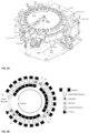
- a vessel 105 After a vessel 105 has been added to the wash wheel 270 at station S1, it will be rotated to station S2, where a wash fluid 150 is dispensed (beginning of stage 4). The contents of the vessel 105 will then be rotated through stations S3-S8 where the paramagnetic particles 120 in the reaction vessel will be drawn to the side of the vessel. It will then be rotated to station S9 (labeled as station A1 in figure 3B ) where the contents of the vessel that are not bound to a paramagnetic particle that is attracted to the side of the vessel by a magnet will be aspirated. The vessel will then be moved to station S10 (labeled as D1 in figure 3B ) where wash buffer will be added to it and the contents of the vessel will be spin mixed.
- stations S11-S18 i.e., the vessel could be magnetized in positions S11-S16, have its contents aspirated in position S17/A2, then have additional buffer added and be mixed in position S18/D2).
- the vessel could then be subjected to another magnetization/aspiration procedure in positions S19-S25, at which point stage 4 of the assay 100 could be treated as complete.
- stage 4 the vessel could be moved to position S1, from which it could be removed using a pick and place device to a reaction build carriage for dispensing of the second reagent 155 (stage 5). At this point, it could then be returned to the wash wheel for an additional magnetization + aspiration cycle (i.e., stage 6), either directly or after being subjected to additional mixing and/or incubation (e.g., in an incubation wheel).
- stage 6 additional magnetization + aspiration cycle of stage 6 would be performed in the same manner as described above for stage 4 (i.e., wash buffer would be dispensed at positions QS, D1 and D2, the contents of the buffer would be aspirated in positions A1, A2 and A3, etc.).
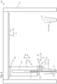
- the example pipetting system 510 is configured to transfer fluids between a first probe receiving station PS1 (e.g., a reagent pack, a sample vessel, etc.) and a second probe receiving station PS2 (e.g., a station along the periphery of wash wheel 270).
- a first probe receiving station PS1 e.g., a reagent pack, a sample vessel, etc.
- second probe receiving station PS2 e.g., a station along the periphery of wash wheel 270.
- first actuator 514 mounted to a first frame 512 mounted to the frame of the instrument.
- the first actuator 514 is a linear actuator that provides movement along displacement d1.
- a sign convention has been defined with respect to the displacement d1.
- a first direction d1+ and an opposite second direction d1- have been defined for displacement d1.
- the example pipetting system 510 of figure 4 also includes a second frame 516.
- the second frame 116 may be mounted to the first actuator 514, and a second actuator 518 may be mounted to the second frame 516.
- the second actuator 518 is a linear actuator that provides movement along displacement d2.
- a sign convention has been defined with respect to the displacement d2.
- a first direction d2+ and an opposite second direction d2- have been defined for displacement d2.
- the displacements d1 and d2 are perpendicular. In other embodiments, the displacements d1 and d2 may be non-perpendicular (e.g., skew, parallel, etc.).
- the first actuator 514 axially aligns the probe P with the desired probe receiving station PS, PS1 and thereby aligns the axes A and A0.
- the probe P and the probe receiving station PS1 of the example pipetting system 510 are aligned when the first actuator 514 is at an actuated position dp1.
- the second actuator 518 may move the probe P along its axis A and thereby along a probe path 300 (e.g., away from an actuated position ap1 of the second actuator 518).
- a clinical analyzer may incorporate multiple pipetting systems, for purposes such as allowing specialization of various assemblies.
- pipetting systems used to transfer reagents from reagent packs to a reaction vessel may be different from pipetting systems used to transfer samples from a sample vessel to a reaction vessel.
- the pipettor used for transferring reagents may have additional specialization to aid in this task.
- a reagent pipettor may be outfitted with a tip that allows it to perform ultrasonic mixing of a reagent in a reagent pack before aspirating it for transport to a reaction vessel, thereby ensuring that the aspirated reagent would not be impacted by any settling that may have taken place in the reagent pack.
- Sample pipettors may similarly be specialized.
- sample pipettors adapted to move portions of a sample either directly to a particular test (which would be done by a sample precision pipettor), or (via a sample aliquot pipettor) to a holding area (e.g., a sample wheel) in which the portion of the sample may be held for use in a later test (including, in some cases, a reflex test).
- a holding area e.g., a sample wheel
- Multiple pipetting systems may also be incorporated for reasons besides supporting multiple workflows. For example, some instruments may be provided with multiple pipetting systems to avoid individual pipetting systems becoming bottlenecks.
- pipetting system(s) such as shown in figure 4 may be present in clinical analyzers that are implemented based on this disclosure, such pipetting systems are not a requirement, and other types of pipetting arrangements, either in combination with or as alternatives to systems such as shown in figure 4 may also be present.
- various vessel positions e.g., positions S0 to S27 from figure 3
- the above discussion of variations like the discussion of the pipetting system 510 of figure 4 , should be understood as being illustrative only, and should not be treated as limiting.
- the probe washer 530 could also be moved relative to the probe path 300 by the third actuator 120 (e.g., to an actuated position pw1) such that the probe washer 530 clears the probe path 300 when the probe P dispenses, aspirates, prepares for dispensing, and/or prepares for aspirating and thereby allows the probe P to pass by the probe washer 530.
- the third actuator 120 e.g., to an actuated position pw1
- a probe washing arrangement may include a cleaning fluid supply, a pump for transferring cleaning fluid into and/or out of a probe washer 530, and one or more valves for configuring fluid flow through the probe washer.
- a probe washing arrangement may include a cleaning fluid supply, a pump for transferring cleaning fluid into and/or out of a probe washer 530, and one or more valves for configuring fluid flow through the probe washer.
- analyzers may be equipped with wash stations that are separate from pipetting assemblies, either as alternatives to, or in addition to, washing arrangements such as shown in figure 5 .
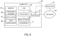
- FIG. 6 that figure illustrates an exemplary computer system 49 that can be integrated into, or connected with, a clinical analyzer, and that could control various actions of the analyzer such as by sending commands to a wash wheel 270, a pipettor assembly 110 and/or other components.
- a computer system 49 may include a processor 51, a memory 53, a mass storage memory device 55, an input/output (I/O) interface 57, and a Human Machine Interface (HMI) 59.
- Computer system 49 may also be operatively coupled to one or more external resources 61 via a network 63 or I/O interface 57.
- External resources may include, but are not limited to, servers, databases, mass storage devices, peripheral devices, cloud-based network services, or any other suitable computer resource that may used by computer system 49.
- a database 71 may reside on mass storage memory device 55, and may be used to collect and organize data used by the various systems and modules described herein.
- Database 71 may include data and supporting data structures that store and organize the data.
- database 71 may be arranged with any database organization or structure including, but not limited to, a relational database, a hierarchical database, a network database, or combinations thereof.
- a database management system in the form of a computer software application executing as instructions on processor 51 may be used to access the information or data stored in records of the database 71 in response to a query, where a query may be dynamically determined and executed by operating system 65, other applications 67, or one or more modules.
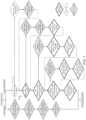
- an entire camera based fault detection sequence may take place during an initial check from the luminometer based diagnostic steps. For instance, an embodiment following figure 7 may complete all of the camera steps 1a-4a while the first luminometer diagnostic step 1b is taking place.
- the mixed reagent in the reaction vessel would be imaged by a digital camera (e.g., a camera located proximate the dispensing position of the reaction vessel, or a camera located elsewhere on the instrument to which the reaction vessel would be moved for purposes of imaging), and a darkness check would be performed on the captured image(s) to determine if there had been a fault in the treatment of the PmP diagnostic reagent (e.g., if the mixed reagent in the reaction vessel had a grayscale value that was lighter or darker than expected). Additionally, in some embodiments this may be performed with multiple vessels (e.g., five vessels), either in parallel or sequentially, to provide additional information that could be used for determining if there had been a fault in the handling of the PmP diagnostic reagent.
- a digital camera e.g., a camera located proximate the dispensing position of the reaction vessel, or a camera located elsewhere on the instrument to which the reaction vessel would be moved for purposes of imaging
- a darkness check would be performed on
- This type of message may also include information on one or more steps to perform to remedy the fault - such as replacing a reagent pipettor tip used in performing the ultrasonic mix, recalibrating the ultrasonics, or replacing the instrument's ultrasonic transducer. If this remediation was unsuccessful, a call could be placed to request that a remote service engineer be dispatched to the instrument, and the remote service engineer could be informed of where the fault had taken place (e.g., in paramagnetic particle resuspension in the reagent pack) and what remediation activities had already been tried.
- This combination could then be sent to the wash wheel where it could be magnetized (potentially without any related activities of dispensing further reagents, aspirating fluid or spin mixing) under the control of a computer such as shown in figure 6 .
- the reaction vessel could be moved back to the pipetting position and subjected to ultrasonic mixing to resuspend the particles in the solution.
- the resuspended mixture could be imaged by a digital camera for a darkness check in the same manner as described for the previous diagnostic step 1a.
- an embodiment following figure 7 may either proceed to remediation (if a fault was identified) or to the next diagnostic step 4a.
- the remediation may proceed by a computer such as shown in figure 6 providing a message on its interface indicating that there had been a fault in the resuspension of particles within the wash wheel, and may potentially accompany that message with one or more steps that could be used to remedy the fault - such as making sure that the position of the spin mixer was properly aligned to the reaction vessel and/or replacing a spin mixer.
- step 4a of checking for faults in retention of paramagnetic particles that step could be used to determine if there were faults in the instrument's ability to flush a reaction vessel after an assay.
- performing this step may involve execution of two sub-processes, one for creating a particle retention calibration curve (which may take place contemporaneously with the other diagnostic steps, or may be done in advance, such as before or at the time the instrument is installed), and one for using that calibration curve to identify faults in the operation of the instrument.
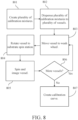
- figure 8 illustrates a set of steps that may be performed in some embodiments to create this curve.
- a computer such as shown in figure 6 could cause an instrument to create a test mixture of ASD reagent and wash buffer (e.g., 50 ⁇ L of ASD reagent and 150 ⁇ L of wash buffer) in each of a plurality of vessels (e.g., five vessels), and then send those vessels to the wash wheel to undergo a full wash process (e.g., adding wash buffer, spin mixing and aspirating the vessel being tested at least twice) without adding substrate or ALP.
- ASD reagent and wash buffer e.g., 50 ⁇ L of ASD reagent and 150 ⁇ L of wash buffer
- a full wash process e.g., adding wash buffer, spin mixing and aspirating the vessel being tested at least twice
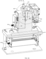
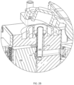
- the substrate blank check 1b can test the instrument's chemiluminescence detection subsystem (i.e., the luminometer, as illustrated in figures 2A-2B , along with the components used to dispense substrate into a reaction vessel in stage 7 of an assay 100 as illustrated in figure 1 ) to ensure that it does not generate spurious light detection signals.
- the instrument's chemiluminescence detection subsystem i.e., the luminometer, as illustrated in figures 2A-2B , along with the components used to dispense substrate into a reaction vessel in stage 7 of an assay 100 as illustrated in figure 1 .
- those additional steps may include a substrate volume check 1.2 performed by a camera.
- this type of check it may be performed by dispensing a predefined volume of substrate into a plurality of vessels (e.g., dispensing 200 ⁇ L of substrate in to each of ten vessels), then capturing images of those vessels and calculating the volume of substrate in each of them (e.g., based on the distance between the meniscus of the substrate and the bottom of the vessel along with the cross sectional area of the vessel).
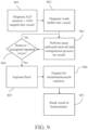
- wash efficiency check step 2b this may be performed by a process such as shown in figure 9 .
- the ASD reagent and ALP solution preferably ALP solution from an ASD pack
- An additional volume of wash buffer e.g., 300 ⁇ L of wash buffer
- this check 2.1 could be done by using the probes that would be used to dispense wash buffer into a reaction vessel during an assay to dispense a known quantity (e.g., 200 ⁇ L) wash buffer into corresponding sets of test vessels, then rotating those test vessels to a position on the wash wheel proximate to a camera (e.g., a substrate dispensing position), imaging the vessels and calculating the volume of wash buffer actually added to the vessels using the images.
- a known quantity e.g. 200 ⁇ L
- the process could proceed with one or more extended remediation steps such as replacing the wash dispense syringes (i.e., the probes) that would be used to dispense wash buffer into the reaction vessels where the discrepancy was noted.
- extended remediation steps such as replacing the wash dispense syringes (i.e., the probes) that would be used to dispense wash buffer into the reaction vessels where the discrepancy was noted.
- an additional extended diagnostic step 2.2 of checking residual volume by camera could be performed.
- one or more remedial steps may be performed to address that failure. These steps could include replacing the aspirate probe(s) corresponding to the vessel(s) where the failure had been detected, ensuring that the aspirate probe(s) corresponding to the vessel(s) where the failure had been detected were properly aligned to their reaction vessel station(s), and/or replacing the peristaltic pump tubing that would be used by the aspiration probe(s) to move the unbound liquid from a reaction vessel to a waste receptacle.
- a diagnostic process such as shown in figure 7 could proceed with an additional extended diagnostic step of performing an aspiration probe carryover check 2.3.
- an additional extended diagnostic step it could be performed by, for example, adding diagnostic ALP solution and wash buffer to each of a plurality of vessels (e.g., adding 200 ⁇ L of diagnostic ALP solution and 200 ⁇ L of wash buffer to each of ten vessels), sending the vessels to the position from which fluid would be aspirated from reaction vessels being washed between assays, aspirating the fluid, preparing the vessels for chemiluminescent reaction (e.g., adding substrate, spin mixing and incubating, as described in the context of figure 9 ), and then reading them with the luminometer.
- this step could be used to evaluate the functioning of the instrument's reagent dispensing subsystem (i.e., the components used to handle reagents during an assay, such as reagent pipettors, and ultrasonic transducers).
- the instrument's reagent dispensing subsystem i.e., the components used to handle reagents during an assay, such as reagent pipettors, and ultrasonic transducers.
- one or more remedial actions such as aligning the reagent pipettor with the reaction vessel and/or the reagent pack, could be taken to address the inconsistency. If these actions were successful (or if no inconsistency was detected) a process such as shown in figure 7 could proceed to the next diagnostic step 4b. Otherwise, one or more extended diagnostic steps may be performed to try and identify a root cause of the inconsistency and, if the root cause of the inconsistency could be identified, to remediate it.
- remedial actions could include checking reagent pipettor perpendicularity, replacing the tip of reagent pipettor, and/or replacing the ultrasonic transducer.
- an additional extended diagnostic step could be performed in the form of a reagent pipettor carryover check 3.3.
- the reagent volume carryover check may be performed in a manner very similar to the aspirate probe carryover check 2.3 discussed previously.
- 50 ⁇ L of diagnostic ALP solution and wash buffer could be added alternately to each of ten vessels, then the vessels could be prepared for a chemiluminescent reaction by adding 200 ⁇ L of substrate, mixing and incubating them, and then reading whatever chemiluminescent light was generated using the luminometer.
- these extended diagnostic steps may include a luminometer sample volume linearity check 4.2.
- the performance of this type of check 4.2 may begin with using a reagent pipettor to add a predetermined volume of diagnostic ALP solution to each of a plurality of vessels that would act as sample vessels for this test (e.g., adding 100 ⁇ L of ALP solution to each of 30 vessels).
- the sample precision pipettor may then be used to move portions of that solution to vessels that will act as reaction vessels for the test, and the reagent pipettor can be used to add wash buffer to those vessels so that the total amount of fluid in each of them is the same regardless of how much ALP solution was added by the sample precision pipettor.
- ten reaction vessels could be filled with 50 ⁇ L of ALP solution, ten more could be filled with 25 ⁇ L of ALP solution and 25 ⁇ L of wash buffer, and a final ten could be filled with 10 ⁇ L of ALP solution and 40 ⁇ L of wash buffer.
- This information could then be used to address the issue (e.g., by adjusting the operation of the sample precision pipettor so the immersion height would match the instrument's design parameters). Alternatively, it could be used to proceed to further remediation/diagnostic actions, such as calling a field service engineer and informing him or her that there appeared to be a problem with the immersion height of the sample precision pipettor or that there was a failure in the luminometer sample volume check where no root cause had been found, as appropriate. Ultimately, once the failure in the luminometer sample volume check 4b had been remedied, the process of evaluating the operation of the remaining system(s), if any, of the instrument could proceed.
- one or more remedial actions such as investigating the level sense function of the sample aliquot pipettor, and/or replacing the sample aliquot syringe used on that pipettor (i.e., the pipettor tip), either to avoid, or as a prelude to, invoking additional support resources for addressing the detected fault.
Landscapes
- Immunology (AREA)
- Health & Medical Sciences (AREA)
- General Health & Medical Sciences (AREA)
- Chemical & Material Sciences (AREA)
- Analytical Chemistry (AREA)
- Biochemistry (AREA)
- Physics & Mathematics (AREA)
- General Physics & Mathematics (AREA)
- Life Sciences & Earth Sciences (AREA)
- Pathology (AREA)
- Engineering & Computer Science (AREA)
- Quality & Reliability (AREA)
- Automatic Analysis And Handling Materials Therefor (AREA)
- Investigating Or Analysing Materials By The Use Of Chemical Reactions (AREA)
- Investigating Or Analysing Biological Materials (AREA)
Priority Applications (1)
| Application Number | Priority Date | Filing Date | Title |
|---|---|---|---|
| EP23198468.3A EP4289510A3 (en) | 2018-12-28 | 2019-12-27 | Clinical analyzer automated system diagnostics |
Applications Claiming Priority (2)
| Application Number | Priority Date | Filing Date | Title |
|---|---|---|---|
| US201862785863P | 2018-12-28 | 2018-12-28 | |
| PCT/US2019/068650 WO2020139989A1 (en) | 2018-12-28 | 2019-12-27 | Clinical analyzer automated system diagnostics |
Related Child Applications (2)
| Application Number | Title | Priority Date | Filing Date |
|---|---|---|---|
| EP23198468.3A Division EP4289510A3 (en) | 2018-12-28 | 2019-12-27 | Clinical analyzer automated system diagnostics |
| EP23198468.3A Division-Into EP4289510A3 (en) | 2018-12-28 | 2019-12-27 | Clinical analyzer automated system diagnostics |
Publications (3)
| Publication Number | Publication Date |
|---|---|
| EP3903109A1 EP3903109A1 (en) | 2021-11-03 |
| EP3903109A4 EP3903109A4 (en) | 2023-03-08 |
| EP3903109B1 true EP3903109B1 (en) | 2025-04-16 |
Family
ID=71129317
Family Applications (2)
| Application Number | Title | Priority Date | Filing Date |
|---|---|---|---|
| EP19903480.2A Active EP3903109B1 (en) | 2018-12-28 | 2019-12-27 | Method of operating and diagnosing faults in a laboratory instrument |
| EP23198468.3A Pending EP4289510A3 (en) | 2018-12-28 | 2019-12-27 | Clinical analyzer automated system diagnostics |
Family Applications After (1)
| Application Number | Title | Priority Date | Filing Date |
|---|---|---|---|
| EP23198468.3A Pending EP4289510A3 (en) | 2018-12-28 | 2019-12-27 | Clinical analyzer automated system diagnostics |
Country Status (5)
| Country | Link |
|---|---|
| US (2) | US12372544B2 (cg-RX-API-DMAC7.html) |
| EP (2) | EP3903109B1 (cg-RX-API-DMAC7.html) |
| JP (2) | JP7791712B2 (cg-RX-API-DMAC7.html) |
| CN (2) | CN121805601A (cg-RX-API-DMAC7.html) |
| WO (1) | WO2020139989A1 (cg-RX-API-DMAC7.html) |
Families Citing this family (11)
| Publication number | Priority date | Publication date | Assignee | Title |
|---|---|---|---|---|
| DE102019120494A1 (de) * | 2019-07-30 | 2021-02-04 | Endress+Hauser Conducta Gmbh+Co. Kg | Verfahren zur Überprüfung, Verifizierung, Kalibrierung oder Justierung eines automatischen Analysegeräts |
| JP2021053019A (ja) * | 2019-09-30 | 2021-04-08 | 株式会社三洋物産 | 遊技機 |
| KR102608516B1 (ko) * | 2021-07-16 | 2023-12-04 | (주)마이크로디지탈 | 복잡 시료 추출용 카트리지 시스템 및 복잡 시료 추출 방법 |
| JPWO2023176398A1 (cg-RX-API-DMAC7.html) * | 2022-03-17 | 2023-09-21 | ||
| EP4290528A1 (en) | 2022-06-07 | 2023-12-13 | Tecan Trading AG | Log file evaluation of laboratory automation device with state machines |
| WO2024054890A1 (en) * | 2022-09-07 | 2024-03-14 | Siemens Healthcare Diagnostics Inc. | Systems and methods for determining test result accuracies in diagnostic laborabory systems |
| WO2025155701A1 (en) | 2024-01-16 | 2025-07-24 | Beckman Coulter, Inc. | Automated clinical analyzer with alternative substrate and method of use |
| CN122535823A (zh) | 2024-01-16 | 2026-08-07 | 贝克曼库尔特有限公司 | 用于自动化临床分析仪的替代底物包和使用方法 |
| CN120652091A (zh) * | 2024-03-13 | 2025-09-16 | 广州万孚生物技术股份有限公司 | 孵育装置及化学发光免疫分析仪 |
| WO2026015434A1 (en) | 2024-07-08 | 2026-01-15 | Beckman Coulter, Inc. | Alternative substrate for automated clinical analyzer and methods of use |
| WO2026122760A1 (en) | 2024-12-06 | 2026-06-11 | Beckman Coulter, Inc. | Coordinating laboratory instrument operation |
Family Cites Families (89)
| Publication number | Priority date | Publication date | Assignee | Title |
|---|---|---|---|---|
| JP3031237B2 (ja) | 1996-04-10 | 2000-04-10 | 株式会社日立製作所 | 検体ラックの搬送方法及び検体ラックを搬送する自動分析装置 |
| AU702209B2 (en) | 1996-07-16 | 1999-02-18 | Roche Diagnostics Gmbh | Analytical system with means for detecting too small sample volumes |
| JP3889877B2 (ja) | 1997-04-10 | 2007-03-07 | 株式会社日立製作所 | 自動分析装置およびその支援システム |
| JP4217237B2 (ja) | 1997-04-10 | 2009-01-28 | 株式会社日立製作所 | 自動分析装置およびその支援システム |
| JP4058081B2 (ja) | 1997-04-10 | 2008-03-05 | 株式会社日立製作所 | 自動分析装置、その支援システム、および、記憶媒体 |
| EP0871034B1 (en) | 1997-04-10 | 2007-03-07 | Hitachi, Ltd. | Automatic analyzer and support system therefor |
| EP0990908A1 (de) * | 1998-09-30 | 2000-04-05 | F. Hoffmann-La Roche Ag | Analysenautomat mit Mitteln zur Überwachung von Pipettiervorgängen |
| JP3727481B2 (ja) | 1999-02-04 | 2005-12-14 | 株式会社日立製作所 | 自動分析方法及び装置 |
| US6251624B1 (en) | 1999-03-12 | 2001-06-26 | Akzo Nobel N.V. | Apparatus and method for detecting, quantifying and characterizing microorganisms |
| JP3598019B2 (ja) | 1999-06-16 | 2004-12-08 | 株式会社日立製作所 | 自動分析装置 |
| EP1107159B1 (en) | 1999-11-30 | 2009-04-29 | Sysmex Corporation | Quality control method and device therefor |
| AU777102B2 (en) * | 2000-01-13 | 2004-09-30 | Ortho-Clinical Diagnostics, Inc. | Failure detection in automated clinical analyzers |
| US20020064881A1 (en) | 2000-11-30 | 2002-05-30 | Devlin William Jackson | Method for automatically storing and reprocessing patient specimen's in an automatic clinical analyzer |
| US20020064884A1 (en) | 2000-11-30 | 2002-05-30 | Devlin William Jackson | Method for automatically storing and reprocessing patient specimen's in an automatic clinical analyzer |
| US6907545B2 (en) | 2001-03-02 | 2005-06-14 | Pitney Bowes Inc. | System and method for recognizing faults in machines |
| JP4006203B2 (ja) * | 2001-08-21 | 2007-11-14 | 株式会社日立製作所 | 自動分析装置及び化学分析方法の精度管理方法 |
| JP5193408B2 (ja) * | 2001-09-13 | 2013-05-08 | ベックマン コールター, インコーポレイテッド | 自動分析装置 |
| JP4117181B2 (ja) * | 2002-11-21 | 2008-07-16 | 株式会社日立ハイテクノロジーズ | 自動分析装置 |
| JP3840450B2 (ja) * | 2002-12-02 | 2006-11-01 | 株式会社日立ハイテクノロジーズ | 分析装置 |
| JP3908655B2 (ja) | 2002-12-13 | 2007-04-25 | 三菱電機株式会社 | 通信装置及び通信方法 |
| JP4276894B2 (ja) * | 2003-05-21 | 2009-06-10 | 株式会社日立ハイテクノロジーズ | 異常検出システム及び異常検出方法 |
| US7185288B2 (en) * | 2003-07-18 | 2007-02-27 | Dade Behring Inc. | Operator interface module segmented by function in an automatic clinical analyzer |
| US20050136542A1 (en) | 2003-12-19 | 2005-06-23 | Beckman Coulter, Inc. | Stabilized liquid reference solutions |
| US20050249634A1 (en) | 2004-05-10 | 2005-11-10 | Devlin William J Sr | Calibration solution system for use in an automatic clinical analyzer |
| US8069239B2 (en) | 2004-07-20 | 2011-11-29 | Beckman Coulter, Inc. | Centralized monitor and control system for laboratory instruments |
| US20060047363A1 (en) | 2004-08-31 | 2006-03-02 | Farrelly Philip J | Machine vision system for lab workcells |
| JP4576307B2 (ja) | 2005-09-12 | 2010-11-04 | 株式会社日立ハイテクノロジーズ | 自動分析装置 |
| JP2007108136A (ja) | 2005-10-17 | 2007-04-26 | Mitsubishi Kagaku Bio-Clinical Laboratories Inc | 分析精度管理システム |
| US20070105214A1 (en) | 2005-11-09 | 2007-05-10 | Irm, Llc | Automated cellular assaying systems and related components and methods |
| US7661013B2 (en) | 2006-01-13 | 2010-02-09 | Agilent Technologies, Inc. | System and method for error recovery |
| JP4818744B2 (ja) | 2006-02-09 | 2011-11-16 | シスメックス株式会社 | 試料測定装置 |
| US8055474B1 (en) | 2006-05-16 | 2011-11-08 | Red X Holdings Llc | Diagnostic systems and methods |
| CN101449168A (zh) * | 2006-05-17 | 2009-06-03 | 奥林巴斯株式会社 | 洗净装置及自动分析装置 |
| JP2008058123A (ja) | 2006-08-31 | 2008-03-13 | Hitachi High-Technologies Corp | 自動分析装置 |
| EP2077446A1 (en) | 2006-10-13 | 2009-07-08 | Olympus Corporation | Method of determining abnormality and analyzer |
| WO2008044312A1 (fr) | 2006-10-13 | 2008-04-17 | Olympus Corporation | Procédé d'identification d'erreur et analyseur |
| FR2909449B1 (fr) | 2006-12-01 | 2014-08-01 | Accessible Conseils Sarl | "procede de controle d'appareils d'analyse delocalisee". |
| JP5191664B2 (ja) | 2007-01-09 | 2013-05-08 | ベックマン コールター, インコーポレイテッド | 分析装置 |
| US7731899B2 (en) * | 2007-02-08 | 2010-06-08 | Biokit, S.A. | Apparatus and methods for dispensing sample holders |
| JP2008209338A (ja) | 2007-02-28 | 2008-09-11 | Hitachi High-Technologies Corp | 自動分析装置 |
| JP2008224439A (ja) * | 2007-03-13 | 2008-09-25 | Olympus Corp | 分析装置および異常特定方法 |
| WO2011084703A2 (en) * | 2009-12-21 | 2011-07-14 | Advanced Liquid Logic, Inc. | Enzyme assays on a droplet actuator |
| JP4969292B2 (ja) | 2007-03-30 | 2012-07-04 | シスメックス株式会社 | 試料分析装置 |
| JP4436853B2 (ja) | 2007-06-18 | 2010-03-24 | シスメックス株式会社 | 精度管理装置および精度管理方法 |
| EP2175259A4 (en) * | 2007-06-19 | 2011-11-02 | Beckman Coulter Inc | ERROR SPECIFICATION METHOD AND ANALYZER |
| JP5089307B2 (ja) * | 2007-09-20 | 2012-12-05 | シスメックス株式会社 | 検体分析装置 |
| JP5486160B2 (ja) * | 2008-02-27 | 2014-05-07 | シスメックス株式会社 | 検体分析装置及びその異常制御方法、並びに検体分析装置用プログラム |
| JP5143630B2 (ja) * | 2008-05-22 | 2013-02-13 | シスメックス株式会社 | 分析装置 |
| EP2172780A1 (en) * | 2008-10-01 | 2010-04-07 | Bayer Technology Services GmbH | Apparatus for automatically performing analyses |
| WO2010067513A1 (ja) | 2008-12-09 | 2010-06-17 | 株式会社 日立ハイテクノロジーズ | 自動分析装置 |
| DE112009003799B4 (de) | 2008-12-26 | 2013-08-08 | Hitachi High-Technologies Corporation | Genauigkeitsmanagementverfahren |
| JP2010230570A (ja) * | 2009-03-27 | 2010-10-14 | Sysmex Corp | 試薬調製装置および検体分析装置 |
| BE1018834A3 (nl) | 2009-07-21 | 2011-09-06 | Praet Peter Van | Inspectie camera gemonteerd op een medische diagnose automaat. |
| CA2712002C (en) | 2009-09-09 | 2016-08-30 | Aastra Technologies Limited | Diagnostics methods for a communications device |
| JP4491505B2 (ja) | 2009-09-24 | 2010-06-30 | 株式会社日立ハイテクノロジーズ | 自動分析装置 |
| JP2011149747A (ja) | 2010-01-20 | 2011-08-04 | Hitachi High-Technologies Corp | 自動分析装置 |
| JP5495884B2 (ja) * | 2010-03-25 | 2014-05-21 | シスメックス株式会社 | 試料分析装置 |
| JP5492676B2 (ja) * | 2010-06-28 | 2014-05-14 | 株式会社日立ハイテクノロジーズ | 自動分析装置 |
| KR20130029128A (ko) * | 2010-07-23 | 2013-03-21 | 베크만 컬터, 인코포레이티드 | 실시간 pcr용 용기 |
| JP5371905B2 (ja) | 2010-07-30 | 2013-12-18 | シスメックス株式会社 | 検体処理装置の管理システム、検体処理装置及び管理装置ならびに管理方法 |
| JP5669528B2 (ja) | 2010-11-17 | 2015-02-12 | 株式会社日立ハイテクノロジーズ | 自動分析装置 |
| US8738548B2 (en) | 2011-06-23 | 2014-05-27 | Bio-Rad Laboratories, Inc. | System and method for determining an optimum QC strategy for immediate release results |
| JP5912320B2 (ja) | 2011-07-20 | 2016-04-27 | 株式会社日立ハイテクノロジーズ | 自動分析装置 |
| EP3865458A1 (en) | 2011-07-29 | 2021-08-18 | Hayward Industries, Inc. | Systems and methods for controlling chlorinators |
| JP5872816B2 (ja) * | 2011-08-03 | 2016-03-01 | シスメックス株式会社 | 検体分析装置 |
| US9664702B2 (en) | 2011-09-25 | 2017-05-30 | Theranos, Inc. | Fluid handling apparatus and configurations |
| CN104067319B (zh) | 2011-11-18 | 2016-08-24 | Fio公司 | 与生物/环境诊断测试设备、用户和消耗品一起使用的质量控制系统、方法和计算机可读介质 |
| US9489251B2 (en) | 2011-12-06 | 2016-11-08 | Bio-Rad Laboratories, Inc. | Supervising and recovering software components associated with medical diagnostics instruments |
| US9194859B2 (en) | 2011-12-23 | 2015-11-24 | Abbott Point Of Care Inc. | Reader devices for optical and electrochemical test devices |
| WO2013096817A2 (en) | 2011-12-23 | 2013-06-27 | Abbott Point Of Care Inc | Integrated test device for optical detection of microarrays |
| CN104081210B (zh) | 2011-12-23 | 2018-11-30 | 雅培医护站股份有限公司 | 具有气动式样本致动的光学测定装置 |
| EP2620764B1 (en) * | 2012-01-25 | 2015-11-04 | Roche Diagniostics GmbH | A luminescence method of detecting an analyte in a liquid sample and analysis system |
| US9810658B2 (en) | 2012-04-18 | 2017-11-07 | Board Of Regents, The University Of Texas System | Method for the detection and quantification of analytes using three-dimensional paper-based devices |
| JP2012163576A (ja) | 2012-05-02 | 2012-08-30 | Beckman Coulter Inc | 分析装置 |
| US9081001B2 (en) * | 2012-05-15 | 2015-07-14 | Wellstat Diagnostics, Llc | Diagnostic systems and instruments |
| JP5972762B2 (ja) | 2012-11-14 | 2016-08-17 | 株式会社日立ハイテクノロジーズ | 自動分析装置 |
| US9176154B2 (en) | 2012-12-12 | 2015-11-03 | Bio-Rad Laboratories, Inc. | Calibration process and system |
| US9787815B2 (en) | 2013-01-21 | 2017-10-10 | Cornell University | Smartphone-based apparatus and method |
| US20140271369A1 (en) * | 2013-03-15 | 2014-09-18 | Abbott Laboratories | System and Method for Processing Both Clinical Chemistry and Immunoassay Tests |
| CA2907504C (en) * | 2013-03-27 | 2023-01-17 | Theranos, Inc. | Methods, devices, and systems for sample analysis |
| EP2811300A1 (en) | 2013-06-07 | 2014-12-10 | Roche Diagniostics GmbH | Calibration for multi-component assays |
| WO2015029595A1 (ja) | 2013-08-27 | 2015-03-05 | 株式会社日立ハイテクノロジーズ | 核酸分析装置およびその装置診断方法 |
| WO2015106008A1 (en) | 2014-01-10 | 2015-07-16 | Idexx Laboratories, Inc. | Chemical analyzer |
| CN106461691A (zh) * | 2014-05-30 | 2017-02-22 | 株式会社日立高新技术 | 自动分析装置 |
| JP6322114B2 (ja) * | 2014-09-30 | 2018-05-09 | シスメックス株式会社 | 検体処理装置 |
| WO2016136438A1 (ja) * | 2015-02-23 | 2016-09-01 | 株式会社日立ハイテクノロジーズ | 自動分析装置 |
| CN108778511A (zh) * | 2016-03-10 | 2018-11-09 | 先锋国际良种公司 | 光介导的聚合酶链式反应扩增和产物检测系统及其使用方法 |
| US10197993B2 (en) | 2016-03-31 | 2019-02-05 | Sysmex Corporation | Method and system for performing quality control on a diagnostic analyzer |
| CN117058416A (zh) | 2016-10-28 | 2023-11-14 | 贝克曼库尔特有限公司 | 物质准备评估系统 |
-
2019
- 2019-12-27 WO PCT/US2019/068650 patent/WO2020139989A1/en not_active Ceased
- 2019-12-27 CN CN202511900446.4A patent/CN121805601A/zh active Pending
- 2019-12-27 EP EP19903480.2A patent/EP3903109B1/en active Active
- 2019-12-27 JP JP2021537780A patent/JP7791712B2/ja active Active
- 2019-12-27 EP EP23198468.3A patent/EP4289510A3/en active Pending
- 2019-12-27 CN CN201980092949.XA patent/CN113474662B/zh active Active
-
2021
- 2021-06-25 US US17/358,366 patent/US12372544B2/en active Active
-
2024
- 2024-06-04 JP JP2024090748A patent/JP2024113054A/ja active Pending
-
2025
- 2025-06-26 US US19/251,405 patent/US20250321240A1/en active Pending
Also Published As
| Publication number | Publication date |
|---|---|
| EP4289510A2 (en) | 2023-12-13 |
| EP4289510A3 (en) | 2024-06-12 |
| JP2024113054A (ja) | 2024-08-21 |
| WO2020139989A1 (en) | 2020-07-02 |
| US20250321240A1 (en) | 2025-10-16 |
| US20210396774A1 (en) | 2021-12-23 |
| EP3903109A1 (en) | 2021-11-03 |
| US12372544B2 (en) | 2025-07-29 |
| EP3903109A4 (en) | 2023-03-08 |
| JP2022516259A (ja) | 2022-02-25 |
| CN113474662B (zh) | 2026-01-06 |
| JP7791712B2 (ja) | 2025-12-24 |
| CN113474662A (zh) | 2021-10-01 |
| CN121805601A (zh) | 2026-04-07 |
Similar Documents
| Publication | Publication Date | Title |
|---|---|---|
| US12372544B2 (en) | Clinical analyzer automated system fault diagnostic methods | |
| US20240091770A1 (en) | Imaging Analyzer For Testing Analytes | |
| CN101881780B (zh) | 一种用于体外诊断的分析装置的单元容器 | |
| JP3990944B2 (ja) | 自動分析装置 | |
| EP1102994B1 (en) | Automated immunoassay apparatus with flexible pick-up arm | |
| JP2001221804A (ja) | 臨床分析を行う分析器における不良を検出する方法 | |
| JP2022516259A5 (cg-RX-API-DMAC7.html) | ||
| JP2011163909A (ja) | 自動分析装置および分注手段の洗浄方法 | |
| US20240426756A1 (en) | Examination apparatus | |
| JP2008224439A (ja) | 分析装置および異常特定方法 | |
| CN116724238A (zh) | 自动分析装置以及自动分析装置中的检体的吸取方法 | |
| EP4495602A1 (en) | Test device | |
| JP7161851B2 (ja) | 免疫測定装置の状態確認方法および免疫測定装置 | |
| EP4495603A1 (en) | Inspection device | |
| JP2015078923A (ja) | 検体前処理装置及び検体検査自動分析システム | |
| WO2025155701A1 (en) | Automated clinical analyzer with alternative substrate and method of use | |
| JP7490671B2 (ja) | 自動分析装置 | |
| JPH07120472A (ja) | 自動分析装置 | |
| WO2025155731A1 (en) | Alternative substrate pack for automated clinical analyzer and methods of use | |
| WO2026015434A1 (en) | Alternative substrate for automated clinical analyzer and methods of use |
Legal Events
| Date | Code | Title | Description |
|---|---|---|---|
| STAA | Information on the status of an ep patent application or granted ep patent |
Free format text: STATUS: THE INTERNATIONAL PUBLICATION HAS BEEN MADE |
|
| PUAI | Public reference made under article 153(3) epc to a published international application that has entered the european phase |
Free format text: ORIGINAL CODE: 0009012 |
|
| STAA | Information on the status of an ep patent application or granted ep patent |
Free format text: STATUS: REQUEST FOR EXAMINATION WAS MADE |
|
| 17P | Request for examination filed |
Effective date: 20210701 |
|
| AK | Designated contracting states |
Kind code of ref document: A1 Designated state(s): AL AT BE BG CH CY CZ DE DK EE ES FI FR GB GR HR HU IE IS IT LI LT LU LV MC MK MT NL NO PL PT RO RS SE SI SK SM TR |
|
| DAV | Request for validation of the european patent (deleted) | ||
| DAX | Request for extension of the european patent (deleted) | ||
| RIC1 | Information provided on ipc code assigned before grant |
Ipc: B03C 1/28 20060101ALI20221122BHEP Ipc: B03C 1/30 20060101ALI20221122BHEP Ipc: B03C 1/033 20060101ALI20221122BHEP Ipc: B03C 1/01 20060101ALI20221122BHEP Ipc: G01N 35/00 20060101AFI20221122BHEP |
|
| A4 | Supplementary search report drawn up and despatched |
Effective date: 20230208 |
|
| RIC1 | Information provided on ipc code assigned before grant |
Ipc: B03C 1/28 20060101ALI20230202BHEP Ipc: B03C 1/30 20060101ALI20230202BHEP Ipc: B03C 1/033 20060101ALI20230202BHEP Ipc: B03C 1/01 20060101ALI20230202BHEP Ipc: G01N 35/00 20060101AFI20230202BHEP |
|
| GRAP | Despatch of communication of intention to grant a patent |
Free format text: ORIGINAL CODE: EPIDOSNIGR1 |
|
| STAA | Information on the status of an ep patent application or granted ep patent |
Free format text: STATUS: GRANT OF PATENT IS INTENDED |
|
| INTG | Intention to grant announced |
Effective date: 20241023 |
|
| GRAJ | Information related to disapproval of communication of intention to grant by the applicant or resumption of examination proceedings by the epo deleted |
Free format text: ORIGINAL CODE: EPIDOSDIGR1 |
|
| STAA | Information on the status of an ep patent application or granted ep patent |
Free format text: STATUS: REQUEST FOR EXAMINATION WAS MADE |
|
| GRAP | Despatch of communication of intention to grant a patent |
Free format text: ORIGINAL CODE: EPIDOSNIGR1 |
|
| STAA | Information on the status of an ep patent application or granted ep patent |
Free format text: STATUS: GRANT OF PATENT IS INTENDED |
|
| INTC | Intention to grant announced (deleted) | ||
| INTG | Intention to grant announced |
Effective date: 20241216 |
|
| GRAS | Grant fee paid |
Free format text: ORIGINAL CODE: EPIDOSNIGR3 |
|
| GRAA | (expected) grant |
Free format text: ORIGINAL CODE: 0009210 |
|
| STAA | Information on the status of an ep patent application or granted ep patent |
Free format text: STATUS: THE PATENT HAS BEEN GRANTED |
|
| AK | Designated contracting states |
Kind code of ref document: B1 Designated state(s): AL AT BE BG CH CY CZ DE DK EE ES FI FR GB GR HR HU IE IS IT LI LT LU LV MC MK MT NL NO PL PT RO RS SE SI SK SM TR |
|
| REG | Reference to a national code |
Ref country code: GB Ref legal event code: FG4D |
|
| P01 | Opt-out of the competence of the unified patent court (upc) registered |
Free format text: CASE NUMBER: APP_13018/2025 Effective date: 20250317 |
|
| REG | Reference to a national code |
Ref country code: CH Ref legal event code: EP Ref country code: DE Ref legal event code: R096 Ref document number: 602019068865 Country of ref document: DE |
|
| REG | Reference to a national code |
Ref country code: IE Ref legal event code: FG4D |
|
| REG | Reference to a national code |
Ref country code: NL Ref legal event code: MP Effective date: 20250416 |
|
| PG25 | Lapsed in a contracting state [announced via postgrant information from national office to epo] |
Ref country code: NL Free format text: LAPSE BECAUSE OF FAILURE TO SUBMIT A TRANSLATION OF THE DESCRIPTION OR TO PAY THE FEE WITHIN THE PRESCRIBED TIME-LIMIT Effective date: 20250416 |
|
| REG | Reference to a national code |
Ref country code: AT Ref legal event code: MK05 Ref document number: 1786040 Country of ref document: AT Kind code of ref document: T Effective date: 20250416 |
|
| PG25 | Lapsed in a contracting state [announced via postgrant information from national office to epo] |
Ref country code: PT Free format text: LAPSE BECAUSE OF FAILURE TO SUBMIT A TRANSLATION OF THE DESCRIPTION OR TO PAY THE FEE WITHIN THE PRESCRIBED TIME-LIMIT Effective date: 20250818 Ref country code: ES Free format text: LAPSE BECAUSE OF FAILURE TO SUBMIT A TRANSLATION OF THE DESCRIPTION OR TO PAY THE FEE WITHIN THE PRESCRIBED TIME-LIMIT Effective date: 20250416 Ref country code: FI Free format text: LAPSE BECAUSE OF FAILURE TO SUBMIT A TRANSLATION OF THE DESCRIPTION OR TO PAY THE FEE WITHIN THE PRESCRIBED TIME-LIMIT Effective date: 20250416 |
|
| REG | Reference to a national code |
Ref country code: LT Ref legal event code: MG9D |
|
| PG25 | Lapsed in a contracting state [announced via postgrant information from national office to epo] |
Ref country code: GR Free format text: LAPSE BECAUSE OF FAILURE TO SUBMIT A TRANSLATION OF THE DESCRIPTION OR TO PAY THE FEE WITHIN THE PRESCRIBED TIME-LIMIT Effective date: 20250717 Ref country code: NO Free format text: LAPSE BECAUSE OF FAILURE TO SUBMIT A TRANSLATION OF THE DESCRIPTION OR TO PAY THE FEE WITHIN THE PRESCRIBED TIME-LIMIT Effective date: 20250716 |
|
| PG25 | Lapsed in a contracting state [announced via postgrant information from national office to epo] |
Ref country code: PL Free format text: LAPSE BECAUSE OF FAILURE TO SUBMIT A TRANSLATION OF THE DESCRIPTION OR TO PAY THE FEE WITHIN THE PRESCRIBED TIME-LIMIT Effective date: 20250416 |
|
| PG25 | Lapsed in a contracting state [announced via postgrant information from national office to epo] |
Ref country code: BG Free format text: LAPSE BECAUSE OF FAILURE TO SUBMIT A TRANSLATION OF THE DESCRIPTION OR TO PAY THE FEE WITHIN THE PRESCRIBED TIME-LIMIT Effective date: 20250416 |
|
| PG25 | Lapsed in a contracting state [announced via postgrant information from national office to epo] |
Ref country code: HR Free format text: LAPSE BECAUSE OF FAILURE TO SUBMIT A TRANSLATION OF THE DESCRIPTION OR TO PAY THE FEE WITHIN THE PRESCRIBED TIME-LIMIT Effective date: 20250416 |
|
| PG25 | Lapsed in a contracting state [announced via postgrant information from national office to epo] |
Ref country code: AT Free format text: LAPSE BECAUSE OF FAILURE TO SUBMIT A TRANSLATION OF THE DESCRIPTION OR TO PAY THE FEE WITHIN THE PRESCRIBED TIME-LIMIT Effective date: 20250416 |
|
| PG25 | Lapsed in a contracting state [announced via postgrant information from national office to epo] |
Ref country code: RS Free format text: LAPSE BECAUSE OF FAILURE TO SUBMIT A TRANSLATION OF THE DESCRIPTION OR TO PAY THE FEE WITHIN THE PRESCRIBED TIME-LIMIT Effective date: 20250716 |
|
| PG25 | Lapsed in a contracting state [announced via postgrant information from national office to epo] |
Ref country code: IS Free format text: LAPSE BECAUSE OF FAILURE TO SUBMIT A TRANSLATION OF THE DESCRIPTION OR TO PAY THE FEE WITHIN THE PRESCRIBED TIME-LIMIT Effective date: 20250816 |
|
| PG25 | Lapsed in a contracting state [announced via postgrant information from national office to epo] |
Ref country code: LV Free format text: LAPSE BECAUSE OF FAILURE TO SUBMIT A TRANSLATION OF THE DESCRIPTION OR TO PAY THE FEE WITHIN THE PRESCRIBED TIME-LIMIT Effective date: 20250416 |
|
| PGFP | Annual fee paid to national office [announced via postgrant information from national office to epo] |
Ref country code: GB Payment date: 20251223 Year of fee payment: 7 |
|
| PG25 | Lapsed in a contracting state [announced via postgrant information from national office to epo] |
Ref country code: DK Free format text: LAPSE BECAUSE OF FAILURE TO SUBMIT A TRANSLATION OF THE DESCRIPTION OR TO PAY THE FEE WITHIN THE PRESCRIBED TIME-LIMIT Effective date: 20250416 Ref country code: SM Free format text: LAPSE BECAUSE OF FAILURE TO SUBMIT A TRANSLATION OF THE DESCRIPTION OR TO PAY THE FEE WITHIN THE PRESCRIBED TIME-LIMIT Effective date: 20250416 |
|
| PGFP | Annual fee paid to national office [announced via postgrant information from national office to epo] |
Ref country code: FR Payment date: 20251230 Year of fee payment: 7 |
|
| REG | Reference to a national code |
Ref country code: DE Ref legal event code: R097 Ref document number: 602019068865 Country of ref document: DE |
|
| PG25 | Lapsed in a contracting state [announced via postgrant information from national office to epo] |
Ref country code: CZ Free format text: LAPSE BECAUSE OF FAILURE TO SUBMIT A TRANSLATION OF THE DESCRIPTION OR TO PAY THE FEE WITHIN THE PRESCRIBED TIME-LIMIT Effective date: 20250416 |
|
| PG25 | Lapsed in a contracting state [announced via postgrant information from national office to epo] |
Ref country code: EE Free format text: LAPSE BECAUSE OF FAILURE TO SUBMIT A TRANSLATION OF THE DESCRIPTION OR TO PAY THE FEE WITHIN THE PRESCRIBED TIME-LIMIT Effective date: 20250416 |
|
| PG25 | Lapsed in a contracting state [announced via postgrant information from national office to epo] |
Ref country code: SK Free format text: LAPSE BECAUSE OF FAILURE TO SUBMIT A TRANSLATION OF THE DESCRIPTION OR TO PAY THE FEE WITHIN THE PRESCRIBED TIME-LIMIT Effective date: 20250416 Ref country code: RO Free format text: LAPSE BECAUSE OF FAILURE TO SUBMIT A TRANSLATION OF THE DESCRIPTION OR TO PAY THE FEE WITHIN THE PRESCRIBED TIME-LIMIT Effective date: 20250416 |
|
| PG25 | Lapsed in a contracting state [announced via postgrant information from national office to epo] |
Ref country code: IT Free format text: LAPSE BECAUSE OF FAILURE TO SUBMIT A TRANSLATION OF THE DESCRIPTION OR TO PAY THE FEE WITHIN THE PRESCRIBED TIME-LIMIT Effective date: 20250416 |
|
| PLBE | No opposition filed within time limit |
Free format text: ORIGINAL CODE: 0009261 |
|
| STAA | Information on the status of an ep patent application or granted ep patent |
Free format text: STATUS: NO OPPOSITION FILED WITHIN TIME LIMIT |
|
| REG | Reference to a national code |
Ref country code: CH Ref legal event code: L10 Free format text: ST27 STATUS EVENT CODE: U-0-0-L10-L00 (AS PROVIDED BY THE NATIONAL OFFICE) Effective date: 20260225 |
|
| 26N | No opposition filed |
Effective date: 20260119 |
|
| PGFP | Annual fee paid to national office [announced via postgrant information from national office to epo] |
Ref country code: DE Payment date: 20251229 Year of fee payment: 7 |
|
| PG25 | Lapsed in a contracting state [announced via postgrant information from national office to epo] |
Ref country code: LT Free format text: LAPSE BECAUSE OF FAILURE TO SUBMIT A TRANSLATION OF THE DESCRIPTION OR TO PAY THE FEE WITHIN THE PRESCRIBED TIME-LIMIT Effective date: 20250416 |
|
| PG25 | Lapsed in a contracting state [announced via postgrant information from national office to epo] |
Ref country code: MC Free format text: LAPSE BECAUSE OF FAILURE TO SUBMIT A TRANSLATION OF THE DESCRIPTION OR TO PAY THE FEE WITHIN THE PRESCRIBED TIME-LIMIT Effective date: 20250416 |
|
| REG | Reference to a national code |
Ref country code: CH Ref legal event code: H13 Free format text: ST27 STATUS EVENT CODE: U-0-0-H10-H13 (AS PROVIDED BY THE NATIONAL OFFICE) Effective date: 20260723 |
|
| PG25 | Lapsed in a contracting state [announced via postgrant information from national office to epo] |
Ref country code: SE Free format text: LAPSE BECAUSE OF FAILURE TO SUBMIT A TRANSLATION OF THE DESCRIPTION OR TO PAY THE FEE WITHIN THE PRESCRIBED TIME-LIMIT Effective date: 20250416 |