EP3901463B1 - Kolbenbegrenzungsstruktur, verdichter und wärmeaustauschvorrichtung - Google Patents
Kolbenbegrenzungsstruktur, verdichter und wärmeaustauschvorrichtung Download PDFInfo
- Publication number
- EP3901463B1 EP3901463B1 EP19898508.7A EP19898508A EP3901463B1 EP 3901463 B1 EP3901463 B1 EP 3901463B1 EP 19898508 A EP19898508 A EP 19898508A EP 3901463 B1 EP3901463 B1 EP 3901463B1
- Authority
- EP
- European Patent Office
- Prior art keywords
- piston
- limiting
- cylinder
- hole
- limiting member
- Prior art date
- Legal status (The legal status is an assumption and is not a legal conclusion. Google has not performed a legal analysis and makes no representation as to the accuracy of the status listed.)
- Active
Links
Images



Classifications
-
- F—MECHANICAL ENGINEERING; LIGHTING; HEATING; WEAPONS; BLASTING
- F04—POSITIVE - DISPLACEMENT MACHINES FOR LIQUIDS; PUMPS FOR LIQUIDS OR ELASTIC FLUIDS
- F04C—ROTARY-PISTON, OR OSCILLATING-PISTON, POSITIVE-DISPLACEMENT MACHINES FOR LIQUIDS; ROTARY-PISTON, OR OSCILLATING-PISTON, POSITIVE-DISPLACEMENT PUMPS
- F04C18/00—Rotary-piston pumps specially adapted for elastic fluids
- F04C18/30—Rotary-piston pumps specially adapted for elastic fluids having the characteristics covered by two or more of groups F04C18/02, F04C18/08, F04C18/22, F04C18/24, F04C18/48, or having the characteristics covered by one of these groups together with some other type of movement between co-operating members
- F04C18/34—Rotary-piston pumps specially adapted for elastic fluids having the characteristics covered by two or more of groups F04C18/02, F04C18/08, F04C18/22, F04C18/24, F04C18/48, or having the characteristics covered by one of these groups together with some other type of movement between co-operating members having the movement defined in group F04C18/08 or F04C18/22 and relative reciprocation between the co-operating members
- F04C18/344—Rotary-piston pumps specially adapted for elastic fluids having the characteristics covered by two or more of groups F04C18/02, F04C18/08, F04C18/22, F04C18/24, F04C18/48, or having the characteristics covered by one of these groups together with some other type of movement between co-operating members having the movement defined in group F04C18/08 or F04C18/22 and relative reciprocation between the co-operating members with vanes reciprocating with respect to the inner member
-
- F—MECHANICAL ENGINEERING; LIGHTING; HEATING; WEAPONS; BLASTING
- F01—MACHINES OR ENGINES IN GENERAL; ENGINE PLANTS IN GENERAL; STEAM ENGINES
- F01C—ROTARY-PISTON OR OSCILLATING-PISTON MACHINES OR ENGINES
- F01C21/00—Component parts, details or accessories not provided for in groups F01C1/00 - F01C20/00
- F01C21/08—Rotary pistons
-
- F—MECHANICAL ENGINEERING; LIGHTING; HEATING; WEAPONS; BLASTING
- F01—MACHINES OR ENGINES IN GENERAL; ENGINE PLANTS IN GENERAL; STEAM ENGINES
- F01C—ROTARY-PISTON OR OSCILLATING-PISTON MACHINES OR ENGINES
- F01C21/00—Component parts, details or accessories not provided for in groups F01C1/00 - F01C20/00
- F01C21/08—Rotary pistons
- F01C21/0809—Construction of vanes or vane holders
- F01C21/0818—Vane tracking; control therefor
- F01C21/0827—Vane tracking; control therefor by mechanical means
- F01C21/0836—Vane tracking; control therefor by mechanical means comprising guiding means, e.g. cams, rollers
-
- F—MECHANICAL ENGINEERING; LIGHTING; HEATING; WEAPONS; BLASTING
- F04—POSITIVE - DISPLACEMENT MACHINES FOR LIQUIDS; PUMPS FOR LIQUIDS OR ELASTIC FLUIDS
- F04C—ROTARY-PISTON, OR OSCILLATING-PISTON, POSITIVE-DISPLACEMENT MACHINES FOR LIQUIDS; ROTARY-PISTON, OR OSCILLATING-PISTON, POSITIVE-DISPLACEMENT PUMPS
- F04C29/00—Component parts, details or accessories of pumps or pumping installations, not provided for in groups F04C18/00 - F04C28/00
-
- F—MECHANICAL ENGINEERING; LIGHTING; HEATING; WEAPONS; BLASTING
- F04—POSITIVE - DISPLACEMENT MACHINES FOR LIQUIDS; PUMPS FOR LIQUIDS OR ELASTIC FLUIDS
- F04C—ROTARY-PISTON, OR OSCILLATING-PISTON, POSITIVE-DISPLACEMENT MACHINES FOR LIQUIDS; ROTARY-PISTON, OR OSCILLATING-PISTON, POSITIVE-DISPLACEMENT PUMPS
- F04C29/00—Component parts, details or accessories of pumps or pumping installations, not provided for in groups F04C18/00 - F04C28/00
- F04C29/04—Heating; Cooling; Heat insulation
-
- F—MECHANICAL ENGINEERING; LIGHTING; HEATING; WEAPONS; BLASTING
- F04—POSITIVE - DISPLACEMENT MACHINES FOR LIQUIDS; PUMPS FOR LIQUIDS OR ELASTIC FLUIDS
- F04C—ROTARY-PISTON, OR OSCILLATING-PISTON, POSITIVE-DISPLACEMENT MACHINES FOR LIQUIDS; ROTARY-PISTON, OR OSCILLATING-PISTON, POSITIVE-DISPLACEMENT PUMPS
- F04C2240/00—Components
- F04C2240/20—Rotors
-
- F—MECHANICAL ENGINEERING; LIGHTING; HEATING; WEAPONS; BLASTING
- F04—POSITIVE - DISPLACEMENT MACHINES FOR LIQUIDS; PUMPS FOR LIQUIDS OR ELASTIC FLUIDS
- F04C—ROTARY-PISTON, OR OSCILLATING-PISTON, POSITIVE-DISPLACEMENT MACHINES FOR LIQUIDS; ROTARY-PISTON, OR OSCILLATING-PISTON, POSITIVE-DISPLACEMENT PUMPS
- F04C2240/00—Components
- F04C2240/30—Casings or housings
-
- F—MECHANICAL ENGINEERING; LIGHTING; HEATING; WEAPONS; BLASTING
- F04—POSITIVE - DISPLACEMENT MACHINES FOR LIQUIDS; PUMPS FOR LIQUIDS OR ELASTIC FLUIDS
- F04C—ROTARY-PISTON, OR OSCILLATING-PISTON, POSITIVE-DISPLACEMENT MACHINES FOR LIQUIDS; ROTARY-PISTON, OR OSCILLATING-PISTON, POSITIVE-DISPLACEMENT PUMPS
- F04C2270/00—Control; Monitoring or safety arrangements
- F04C2270/17—Tolerance; Play; Gap
Definitions
- the invention relates to a field of compressors, and in particular to a piston limiting structure, a compressor, and a heat exchange apparatus.
- a rotary cylinder piston compressor is a compressor based on a crosshead shoe principle, a cylinder thereof is rotated in a cylinder sleeve, a piston is arranged transversely in a piston hole of the cylinder, and reciprocated to be slid in the piston hole, thereby a compression chamber is formed among an end face of the piston, a side wall of the piston hole and an inner wall of the cylinder sleeve.
- a bus of a piston head (namely an end face) should be parallel to a bus of an outer surface of the cylinder, so that a destination of a reciprocating motion of the piston perfectly fits the inner wall of the cylinder sleeve (namely the end face of the piston and the outer surface of the cylinder form a completed cylindrical surface) to complete the exhaust.
- the piston is auto-rotated relative to the cylinder during an operation process, because the lengths of the piston and the piston hole along the circumferential direction everywhere are both varied continuously, once the relative rotation is generated between two parties, the completed cylindrical surface may not be formed by the end face of the piston and the outer surface of the cylinder, the interference between the head of the piston and the inner wall of the cylinder sleeve is caused in a compression process of the piston, so that the collision to the cylinder is generated.
- the rotary cylinder piston compressor is improved by using two solutions in the art known to inventors.
- a cylinder piston compressor is disclosed in CN205895526U .
- a pump is disclosed in US2303969A .
- some embodiments of the disclosure provide a piston limiting structure with high cooperation accuracy and capable of preventing the piston from rotating on its own axis without introducing a clearance volume.
- some embodiments of the disclosure provide a compressor using a circular piston without introducing a clearance volume.
- the disclosure further provides a heat exchange apparatus.
- the claimed invention provides
- the limiting hole penetrates from an end face of the cylinder to the piston hole and is parallel to an axial direction of the cylinder.
- a position of the limiting hole on the cylinder corresponds to a position of 1/2 of an axial length of the piston hole.
- the piston while the piston is reciprocated to be slid in the piston hole, it is satisfied: L1 ⁇ L2 ⁇ S wherein, the L1 is a length of the limiting surface along the axial direction of the piston, the L2 is a length of the limiting member along the axial direction of the piston, and the S is a stroke of the piston slid in the cylinder.
- the limiting surface is a plane, wherein the limiting surface is disposed in a position of 1/2 of a radial height direction of the piston.
- the limiting member abuts against the limiting surface, it is satisfied: D 1 + D 2 2 > L wherein, the D1 is a diameter of a projection of the piston in the axial direction, the D2 is a length of the limiting member in a radial direction of the piston, and the L is a length from a center of the limiting member in the radial direction of the piston to a center of the piston.
- the limiting member abuts against the limiting surface, it is satisfied: L > D 1 ⁇ D 2 2 wherein, the D1 is the diameter of the projection of the piston along the axial direction, the D2 is the length of the limiting member in the radial direction of the piston, and the L is the length from the center of the limiting member in the radial direction of the piston to the center of the piston.
- the limiting hole is extended to a position of 1/2 of an axial height of the cylinder from the end face of the cylinder.
- the number of the limiting hole is one, and it is disposed on an upper end face or a lower end face of the cylinder.
- the number of the limiting holes is two, the two limiting holes are disposed on an upper end face of the cylinder and positioned at two sides of an axis of the cylinder, or the two limiting holes are disposed on a lower end face and positioned at the two sides of an axis of the cylinder, or one of the two limiting holes is disposed on an upper end face of the cylinder and positioned at one side of the axis of the cylinder, and the other is disposed on a lower end face of the cylinder and positioned at the other side of the axis of the cylinder.
- the limiting hole penetrates through the cylinder, and is disposed in at least one side of two sides of the axis of the cylinder.
- the limiting member is a cylindrical limiting pin.
- Some embodiments of the disclosure further provide a compressor, including: a rotation shaft; the above piston limiting structure, wherein the cylinder and the piston are provided with shaft holes penetrating along an axial direction of the cylinder, the shaft holes are used for mounting the rotation shaft; and a cylinder sleeve, wherein the cylinder is disposed in the cylinder sleeve and driven to be rotated by the rotation shaft.
- Some embodiments of the disclosure provide a heat exchange apparatus, including the above piston limiting structure.
- the heat exchange apparatus is an air conditioner.
- Some embodiments of the invention have at least one of the following beneficial effects.
- the cylinder, the piston and the limiting member are included, the cylinder has a piston hole perpendicular to an axial direction of the cylinder and penetrating through the cylinder, a projection of the piston hole in a penetrating direction is circular, the piston is disposed in the piston hole in a form-fit manner and is reciprocated to be slid in the piston hole, the circular piston and the circular piston hole are used, a manufacturability of the piston and the cylinder is good, a machining is convenient, a machining accuracy is guaranteed, a large-scale production is easy, and a distance from the piston hole of the cylinder to the end face of the cylinder is a uniform transition which is similar to an arch bridge structure, the structure is firmer and not easy to be deformed, at the same time, the circular piston is cooperated with the circular piston hole of the cylinder, it is beneficial to control an assembly clearance between the piston and the cylinder, and beneficial to reduce friction power and leakage,
- the side wall of the piston is provided with the limiting surface, the limiting surface does not penetrate two ends of the side wall of the piston along an axial length of the piston, an avoidance groove does not exist between the piston and the inner wall of the cylinder, the limiting surface is not communicated with a volume chamber, and a clearance volume does not be introduced, so that the rotary cylinder compressor is worked more stably.
- the cylinder is provided with a limiting hole penetrating from an outer wall of the cylinder to the piston hole, the limiting member is disposed in the limiting hole in the form-fit manner, the limiting member abuts against the limiting surface to limit the rotation of the piston around an axis of the piston itself.
- the limiting member mounted on the cylinder is arranged to be cooperated with the limiting surface on the piston, an assembly of workpieces is convenient, the machining production is easy, and a matching size between the piston and the cylinder is reduced, so a fit clearance between the piston and the cylinder is effectively controlled, a friction power consumption between the piston and the cylinder is reduced, and the performance of the compressor is improved.
- the limiting hole penetrates from the end face of the cylinder to the piston hole and is parallel to the axial direction of the cylinder, the limiting hole and the limiting member of the cylinder are arranged in a vertical direction, and the limiting member does not interfere the rotation of the cylinder, so that the rotation of the cylinder is more stable and reliable.
- the limiting hole is disposed in a position of 1/2 of the piston hole along the axial direction of the piston hole, while the piston is reciprocated to be slid in the piston hole, it is satisfied: L1-L2 ⁇ S, herein, the L1 is the length of the limiting surface along the axial direction of the piston, the L2 is the length of the limiting member along the axial direction of the piston, and the S is the stroke of the piston slid in the cylinder.
- the length of the limiting surface is greater than a total sum of the limiting member and piston stroke lengths, thereby it is guaranteed that the piston does not collide the limiting member while being reciprocated to be slid, a stability and a reliability are guaranteed.
- the limiting surface is a plane, the machining and assembly of the limiting surface are convenient, and it is guaranteed that the machining accuracy is higher.
- the limiting surface is disposed in a position of 1/2 of a radial height of the piston, while the limiting member abuts against the limiting surface, it is satisfied: D 1 + D 2 2 > L > D 1 ⁇ D 2 2 , wherein, the D1 is a diameter of the piston, the D2 is a length of the limiting member in the radial direction of the piston, and the L is a length from a center of the limiting member in the radial direction of the piston to a center of the piston.
- the limiting member has no cantilever portion, a force to the limiting member indirectly acts on the cylinder while the piston is rotated on its own axis, a stress subjected to the limiting member is reduced, a strength requirement to the limiting member is reduced, and a work stability and reliability of the compressor are improved.
- the limiting hole is extended to a position of 1/2 of an axial height of the cylinder from the end face of the cylinder, if the length of the limiting member is increased, an abutting area between the limiting member and the limiting surface is larger, an intensity of pressure of an abutting portion is small, and it is not easy to deform, and one or more limiting holes is arranged, so that a limiting effect is better.
- the limiting member includes the cylindrical limiting pin, the pin is simple in machining, low in cost, easy to guarantee the accuracy, at the same time, a contact area between the pin and the piston limiting surface is small, a friction force to sliding of the piston is smaller, and sliding interference to a reciprocating motion of the piston is small, so that the compressor is worked more stably.
- the compressor includes a rotation shaft, the above piston limiting structure and the cylinder sleeve, the cylinder and the piston are provided with the shaft holes penetrating along the axial direction of the cylinder, the cylinder is disposed in the cylinder sleeve and driven to be rotated by the rotation shaft, because the compressor has the above piston limiting structure, it has all of the above beneficial effects.
- the above piston limiting structure is included, so the heat exchange apparatus has all of the above beneficial effects.
- a rotary cylinder piston compressor in an art known to inventors includes a flange, a cylinder sleeve, a cylinder, a piston and a rotation shaft, based on a crosshead shoe principle, the piston is reciprocated to be slid relative to the cylinder during a rotation process, thereby two ends of the piston form a compression chamber and an exhaust chamber with the cylinder and the cylinder sleeve, respectively.
- a degree of freedom of auto-rotation of the piston around an axis of the piston itself needs to be limited.
- the piston limiting structure provided by some embodiments of the disclosure is used for the rotary cylinder piston compressor in the art known to inventors, thereby it is achieved that the piston is limited.
- Fig. 1 to Fig. 6 show some embodiments of the piston limiting structure of the disclosure.
- the piston limiting structure includes a cylinder 1, a piston 2 and a limiting member 3.
- the cylinder 1 is a cylindrical cylinder
- an axial direction of the cylinder 1 is provided with an assembling hole 12 penetrating through the cylinder 1
- the assembling hole 12 is configured for a rotation shaft 6 to pass through.
- a peripheral surface of the cylinder 1 is provided with a piston hole 11 perpendicular to a direction of the assembling 12 and penetrating the cylinder 1, and a projection of the piston hole 11 along an axial direction itself is circular.
- the piston 2 is disposed in the piston hole 11 in a form-fit manner and is reciprocated to be slid in the piston hole 11.
- the piston 2 is cooperated with the piston hole 11, the piston 2 is a structure similar to a cylinder, end faces at two ends of the piston 2 are curved surface structures which are cooperated with the piston hole 11 to form a completed cylindrical surface, an axial length of the piston 2 is less than a radial size of the cylinder 1, and the piston 2 is reciprocated to be slid in the cylinder 1.
- a middle portion of the piston 2 is provided with a shaft hole 22 along an axial direction of the cylinder 1, while the piston 2 is mounted in the piston hole 11, the rotation shaft 6 passes through the assembling hole 12 of the cylinder 1 and the shaft hole 22 on the piston 2.
- a side wall of the piston 2 is provided with a limiting surface 21, and the limiting surface 21 does not penetrate two ends of the side wall of the piston 2 along an axial length of the piston 2.
- the limiting surface 21 is set as a limiting plane, it is convenient for machining and forming, at the same time, the limiting surface 21 is disposed on a position of 1/2 of a radial height direction of the piston 2.
- the cylinder 1 is provided with a limiting hole 13 penetrating from an outer wall of the cylinder 1 to the piston hole 11, the limiting member 3 is mounted in the limiting hole 13 in a form-fit manner, the limiting member 3 abuts against the limiting surface 21 to limit the auto-rotation of the piston 2. As shown in Fig.
- the limiting hole 13 penetrates from an end face of the cylinder 1 to the piston hole 11 and is parallel to an axial direction of the cylinder 1, the limiting hole 13 is arranged in a vertical direction of the cylinder 1, so that the limiting member 3 abuts against the limiting surface 21 in the vertical direction, machining and forming of the limiting hole 13 are convenient, and an abutting direction is perpendicular to a rotation direction of the cylinder 1 and the piston 2, the limiting member 3 is not subjected to a rotation torque in a horizontal direction, the limiting structure is more stable and reliable.
- the limiting hole 13 is set as a circular hole, correspondingly the limiting member 3 is set as a cylindrical pin structure, a circular pin is cooperated with the limiting hole 13, for example, a fit clearance between two parties is set as 0-0.05 mm.
- a position of the limiting hole 13 on the cylinder 1 corresponds to a position of 1/2 of an axial direction of the piston hole 11, namely the limiting hole 13 is mounted in a middle position of the piston hole 11 along a length direction.
- the piston 2 under a working state, the piston 2 is reciprocated relative to the limiting member 3, thereby in order to guarantee that the piston 2 may not collide with the limiting member 3 during a process of a reciprocating motion, while the piston 2 is reciprocated to be slid in the piston hole 11, it is satisfied: L1 ⁇ L2 ⁇ S
- the L1 is a length of the limiting surface 21 along an axial direction of the piston 2
- the L2 is a length of the limiting member 3 along the axial direction of the piston 2
- the L2 is a diameter of a cross section of the limiting member 3
- the S is a stroke of the piston slid in the cylinder.
- the length L2 of the limiting member 3 along the axial direction of the piston 2 is longer, correspondingly the length L1 of the limiting surface 21 is also designed to be longer, therefore the length of the limiting surface 21 is reduced by reducing the length of the limiting member 3 along the axial direction of the piston 2, the length of the limiting surface 21 is reduced, correspondingly a sealing distance between the piston 2 and the inner wall of the cylinder 1 becomes longer, so that a sealing effect between the piston 2 and the inner wall of the cylinder is better.
- diameters of the piston 2 and the cylinder 1 are correspondingly designed to be reduced, therefore the mechanical power consumption of the compressor is reduced.
- the D1 is a diameter of a cross section of the piston 2
- the D2 is a length of the limiting member 3 in a radial direction of the piston 2
- D2 is a diameter of a section of the limiting member 3
- the limiting member 3 While L ⁇ D 1 ⁇ D 2 2 , the limiting member 3 is mounted in the limiting hole 13, a bottom end face of the limiting member 3 and a bottom portion of the limiting hole 13 are positioned in the critical state of non-contact, at this moment, the limiting member 3 is a cantilever structure, an upper end of the limiting member 3 needs to be fixed and limited.
- the limiting member 3 While L > D 1 ⁇ D 2 2 , a part of the bottom end face of the limiting member 3 abuts against the bottom portion of the limiting hole 13, the limiting member 3 has no cantilever structure, a force to the limiting member 3 indirectly acts on the cylinder 1 while the piston 2 has a tendency to the auto-rotation, a stress to the limiting member 3 is reduced, and a strength requirement to the limiting member is reduced.
- the limiting hole 13 is extended to a position of 1/2 of an axial height of the cylinder 1 along an end face of the cylinder 1, and a length of the limiting member is increased, so that an abutting area between the limiting member and the limiting surface is larger, a pressure intensity of an abutting portion is small, and it is not easy to be deformed.
- Fig. 7 shows a second implementation mode of the piston limiting structure of the disclosure
- a difference from the above embodiments is that the number of the limiting members 3 is set as two, correspondingly two corresponding limiting holes 13 are arranged on the cylinder 1, the two limiting members 3 are respectively arranged on an upper end face of the cylinder 1 and positioned at two sides of an axis of the cylinder 1, the piston 2 is limited by the two limiting members 3, limiting reliability is improved, implementation parameters and limiting principles thereof are the same as the above embodiments, it is not repeatedly described in the implementation mode.
- Fig. 8 shows a third embodiment of the piston limiting structure of the disclosure, in the embodiment, a difference from the above embodiments is that the limiting hole 13 is disposed at one side of a lower end face of the cylinder 1, implementation parameters and limiting principles are the same as the above embodiments.
- Fig. 9 shows a fourth embodiment of the piston limiting structure of the disclosure, in the embodiment, two limiting holes 13 are arranged, and the two limiting holes 13 are respectively disposed at two sides of the axis of the lower end face of the cylinder 1, implementation parameters and limiting principles are the same as the above embodiments.
- Fig. 10 shows a fifth embodiment of the piston limiting structure of the disclosure, in the embodiment, two limiting holes 13 are arranged, and the two limiting holes 13 are respectively disposed on the upper and lower end faces of the cylinder 1, and the two limiting holes 13 are respectively positioned at two sides of the axis of the cylinder 1, implementation parameters and limiting principles are the same as the above embodiments.
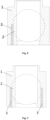
- Fig. 11 shows a sixth embodiment of the piston limiting structure of the disclosure, in the embodiment, the limiting hole 13 penetrates the upper and lower end faces of the cylinder 1, the limiting member 3 is correspondingly disposed in the limiting hole 13, an axial length of the limiting member 3 is less than or equal to an axial length of the cylinder 1 and greater than a half of the axial length of the cylinder 1, implementation parameters and limiting principles are the same as the above embodiments.
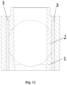
- Fig. 12 shows a seventh embodiment of the piston limiting structure of the disclosure
- the limiting hole 13 penetrates the upper and lower end faces of the cylinder 1
- two limiting holes 13 are arranged, and respectively positioned at two sides of the axis of the cylinder 1
- each of the limiting members 3 is arranged in the corresponding limiting hole 13
- the axial length of the limiting member 3 is less than or equal to the axial length of the cylinder 1 and greater than a half of the axial length of the cylinder 1
- implementation parameters and limiting principles are the same as the above embodiments.
- the limiting member 3 may also be other arbitrary shapes suitable for implementation, for example, a cube, a plate shape and a column shape, this is not limited by the disclosure.
- the disclosure further provides a compressor, as shown in Fig. 1 , the compressor of some embodiments of the disclosure includes a rotation shaft 6, an upper flange 4, a lower flange 5, a cylinder sleeve 7, and the above piston limiting structure, the cylinder 1 is disposed in the cylinder sleeve 7, the rotation shaft 6 successively penetrates the upper flange 4, the cylinder sleeve 7, and the lower flange 5.
- the compressor of the embodiments of the disclosure is based on the crosshead shoe principle, as shown in Fig.
- Some embodiments of the disclosure further provide a heat exchange apparatus, and the heat exchange apparatus includes the above compressor or piston limiting structure.
- the heat exchange apparatus is an air conditioner or a refrigerator.
Landscapes
- Engineering & Computer Science (AREA)
- Mechanical Engineering (AREA)
- General Engineering & Computer Science (AREA)
- Compressor (AREA)
- Pistons, Piston Rings, And Cylinders (AREA)
Claims (14)
- Kolbenbegrenzungsstruktur, umfassend:einen Zylinder (1) und einen Kolben (2), wobei der Zylinder (1) eine Kolbenbohrung (11) aufweist, die senkrecht zu einer axialen Richtung des Zylinders (1) verläuft und den Zylinder (1) durchdringt, wobei ein Vorsprung der Kolbenbohrung (11) in einer Durchdringungsrichtung kreisförmig ist;wobei der Kolben (2) formschlüssig in der Kolbenbohrung (11) angeordnet ist und in einer Hin- und Herbewegung in die Kolbenbohrung (11) gleitet, wobei eine Seitenwand des Kolbens (2) mit einer Begrenzungsfläche (21) bereitgestellt ist; und die Kolbenbegrenzungsstruktur ein Begrenzungselement (3) umfasst,wobei der Zylinder (1) mit einer Begrenzungsbohrung (13) bereitgestellt ist, die von einer Außenwand des Zylinders (1) zu der Kolbenbohrung (11) verläuft, das Begrenzungselement (3) formschlüssig in der Begrenzungsbohrung (13) montiert ist und das Begrenzungselement (3) an der Begrenzungsfläche (21) anliegt, um eine Drehung des Kolbens (2) um seine eigene Achse zu begrenzen, wobei die Begrenzungsfläche (21) nicht durch zwei Enden der Seitenwand des Kolbens (2) entlang einer axialen Richtung des Kolbens (2) hindurchdringt,dadurch gekennzeichnet, dass die Begrenzungsbohrung (13) von einer Endfläche des Zylinders (1) zu der Kolbenbohrung (11) hindurchdringt und parallel zu einer axialen Richtung des Zylinders (1) verläuft.
- Kolbenbegrenzungsstruktur nach Anspruch 1, wobei eine Position der Begrenzungsbohrung (13) auf dem Zylinder (1) einer Position von 1/2 einer axialen Länge der Kolbenbohrung (11) entspricht.
- Kolbenbegrenzungsstruktur nach Anspruch 2, wobei, während der Kolben (2) hin- und herbewegt wird, um in die Kolbenbohrung (1) zu gleiten, die folgende Bedingung erfüllt ist:

- Kolbenbegrenzungsstruktur nach Anspruch 2 oder 3, wobei
die Begrenzungsfläche (21) eine Ebene ist, wobei die Begrenzungsfläche (21) an einer Position von 1/2 einer radialen Höhenrichtung des Kolbens (2) angeordnet ist. - Kolbenbegrenzungsstruktur nach Anspruch 4, wobei,während das Begrenzungselement (3) an der Begrenzungsfläche (31) anliegt, die folgende Bedingung erfüllt ist:
 wobei D1 ein Durchmesser eines Vorsprungs des Kolbens (2) in der axialen Richtung ist, D2 eine Länge des Begrenzungselements (3) in einer radialen Richtung des Kolbens (2) ist und L eine Länge von einer Mitte des Begrenzungselements (3) in der radialen Richtung des Kolbens (2) zu einer Mitte des Kolbens (2) ist.
 - Kolbenbegrenzungsstruktur nach Anspruch 5, wobei,während das Begrenzungselement (3) an der Begrenzungsfläche (21) anliegt, die folgende Bedingung erfüllt ist:
 wobei D1 der Durchmesser des Vorsprungs des Kolbens (2) entlang der axialen Richtung ist, D2 die Länge des Begrenzungselements (3) in der radialen Richtung des Kolbens (2) ist und L die Länge von der Mitte des Begrenzungselements (3) in der radialen Richtung des Kolbens (2) zu der Mitte des Kolbens (2) ist.
 - Kolbenbegrenzungsstruktur nach Anspruch 1, wobei
sich die Begrenzungsbohrung (13) von der Endfläche des Zylinders (1) aus bis zu einer Position von 1/2 einer axialen Höhe des Zylinders (1) erstreckt. - Kolbenbegrenzungsstruktur nach Anspruch 7, wobei
die Anzahl der Begrenzungsbohrung (13) eins beträgt und die Begrenzungsbohrung (13) an einer oberen Endfläche oder einer unteren Endfläche des Zylinders (1) angeordnet ist. - Kolbenbegrenzungsstruktur nach Anspruch 7, wobei
die Anzahl der Begrenzungsbohrungen (13) zwei beträgt, zwei Begrenzungsbohrungen (13) an einer oberen Endfläche des Zylinders (1) angeordnet und auf zwei Seiten einer Achse des Zylinders (1) positioniert sind oder zwei Begrenzungsbohrungen (13) an einer unteren Endfläche angeordnet und auf zwei Seiten einer Achse des Zylinders (1) positioniert sind oder eine von zwei Begrenzungsbohrungen (13) an einer oberen Endfläche des Zylinders (1) angeordnet und auf einer Seite einer Achse des Zylinders (1) positioniert ist und die andere der zwei Begrenzungsbohrungen (13) an einer unteren Endfläche des Zylinders (1) angeordnet und auf der anderen Seite der Achse des Zylinders (1) positioniert ist. - Kolbenbegrenzungsstruktur nach Anspruch 6, wobei
die Begrenzungsbohrung (13) durch den Zylinder (1) hindurchdringt und an mindestens einer Seite von zwei Seiten der Achse des Zylinders (1) angeordnet ist. - Kolbenbegrenzungsstruktur nach einem der Ansprüche 1 bis 3, wobei das Begrenzungselement (3) einen zylindrischen Begrenzungsstift umfasst.
- Kompressor, umfassend:eine Drehwelle (6);die Kolbenbegrenzungsstruktur nach einem der Ansprüche 1 bis 11, wobei der Zylinder (1) und der Kolben (2) mit Wellenbohrungen bereitgestellt sind, die entlang einer axialen Richtung des Zylinders (1) hindurchdringen, wobei die Wellenbohrungen zum Montieren der Drehwelle (6) verwendet werden; undeine Zylinderhülse (7), wobei der Zylinder (1) in der Zylinderhülse (7) angeordnet ist und durch die Drehwelle (6) angetrieben wird, um gedreht zu werden.
- Wärmeaustauschvorrichtung, umfassend die Kolbenbegrenzungsstruktur nach einem der Ansprüche 1 bis 11 oder den Kompressor nach Anspruch 12.
- Wärmeaustauschvorrichtung nach Anspruch 13, wobei die Wärmeaustauschvorrichtung eine Klimaanlage umfasst.
Applications Claiming Priority (2)
| Application Number | Priority Date | Filing Date | Title |
|---|---|---|---|
| CN201811549125.4A CN109555690B (zh) | 2018-12-18 | 2018-12-18 | 活塞限位结构、压缩机及换热设备 |
| PCT/CN2019/106724 WO2020125099A1 (zh) | 2018-12-18 | 2019-09-19 | 活塞限位结构、压缩机及换热设备 |
Publications (3)
| Publication Number | Publication Date |
|---|---|
| EP3901463A1 EP3901463A1 (de) | 2021-10-27 |
| EP3901463A4 EP3901463A4 (de) | 2022-01-12 |
| EP3901463B1 true EP3901463B1 (de) | 2024-10-30 |
Family
ID=65870481
Family Applications (1)
| Application Number | Title | Priority Date | Filing Date |
|---|---|---|---|
| EP19898508.7A Active EP3901463B1 (de) | 2018-12-18 | 2019-09-19 | Kolbenbegrenzungsstruktur, verdichter und wärmeaustauschvorrichtung |
Country Status (4)
| Country | Link |
|---|---|
| US (1) | US11788530B2 (de) |
| EP (1) | EP3901463B1 (de) |
| CN (1) | CN109555690B (de) |
| WO (1) | WO2020125099A1 (de) |
Families Citing this family (3)
| Publication number | Priority date | Publication date | Assignee | Title |
|---|---|---|---|---|
| CN108916045B (zh) * | 2018-07-18 | 2024-04-02 | 珠海格力电器股份有限公司 | 泵体组件、流体机械及换热设备 |
| CN109555690B (zh) * | 2018-12-18 | 2024-07-23 | 珠海格力电器股份有限公司 | 活塞限位结构、压缩机及换热设备 |
| CN110701046B (zh) * | 2019-11-12 | 2020-09-08 | 珠海格力电器股份有限公司 | 压缩缸组件、转缸活塞压缩机及换热设备 |
Family Cites Families (11)
| Publication number | Priority date | Publication date | Assignee | Title |
|---|---|---|---|---|
| US2303969A (en) * | 1940-08-03 | 1942-12-01 | Falk Corp | Pump |
| JPH10281052A (ja) | 1997-02-06 | 1998-10-20 | Kayseven Co Ltd | ポンプ |
| KR20020015351A (ko) * | 1999-06-18 | 2002-02-27 | 고구치 유죠 | 로터리식 실린더장치 |
| DE102013017944A1 (de) * | 2013-10-29 | 2015-04-30 | Linde Aktiengesellschaft | Verfahren zur Klopfregelung bei einem Kolbenverdichter |
| CN205895526U (zh) | 2016-07-28 | 2017-01-18 | 珠海格力节能环保制冷技术研究中心有限公司 | 一种转缸活塞压缩机 |
| CN106065854B (zh) * | 2016-07-28 | 2017-11-24 | 珠海格力节能环保制冷技术研究中心有限公司 | 一种转缸活塞压缩机 |
| CN106089717A (zh) * | 2016-07-28 | 2016-11-09 | 珠海格力节能环保制冷技术研究中心有限公司 | 一种压缩机泵体及压缩机 |
| CN109555694B (zh) | 2018-12-18 | 2024-09-24 | 珠海格力电器股份有限公司 | 活塞限位结构、压缩机及换热设备 |
| CN109555695B (zh) | 2018-12-18 | 2024-06-11 | 珠海格力电器股份有限公司 | 活塞限位结构、压缩机及换热设备 |
| CN209604247U (zh) * | 2018-12-18 | 2019-11-08 | 珠海格力电器股份有限公司 | 活塞限位结构、压缩机及换热设备 |
| CN109555690B (zh) | 2018-12-18 | 2024-07-23 | 珠海格力电器股份有限公司 | 活塞限位结构、压缩机及换热设备 |
-
2018
- 2018-12-18 CN CN201811549125.4A patent/CN109555690B/zh active Active
-
2019
- 2019-09-09 US US17/283,004 patent/US11788530B2/en active Active
- 2019-09-19 WO PCT/CN2019/106724 patent/WO2020125099A1/zh not_active Ceased
- 2019-09-19 EP EP19898508.7A patent/EP3901463B1/de active Active
Also Published As
| Publication number | Publication date |
|---|---|
| US11788530B2 (en) | 2023-10-17 |
| WO2020125099A1 (zh) | 2020-06-25 |
| US20210348610A1 (en) | 2021-11-11 |
| CN109555690B (zh) | 2024-07-23 |
| EP3901463A1 (de) | 2021-10-27 |
| EP3901463A4 (de) | 2022-01-12 |
| CN109555690A (zh) | 2019-04-02 |
Similar Documents
| Publication | Publication Date | Title |
|---|---|---|
| US11788530B2 (en) | Piston limiting structure, compressor, and heat exchange apparatus | |
| EP1119708B1 (de) | Kolbenkompressor mit linearmotor | |
| EP1520106B1 (de) | Resonanzanordnung für einen linear oszilierend angetriebenen kompressor | |
| EP3901464B1 (de) | Kolbenbegrenzungsstruktur, verdichter und wärmeaustauschvorrichtung | |
| US20120152110A1 (en) | Compressor system and frame | |
| CN117145769A (zh) | 流体机械和换热设备 | |
| JP2011226471A (ja) | 圧縮機 | |
| CN109555694B (zh) | 活塞限位结构、压缩机及换热设备 | |
| CN102084132A (zh) | 制冷剂压缩机 | |
| CN109555695B (zh) | 活塞限位结构、压缩机及换热设备 | |
| BR0104001B1 (pt) | arranjo de montagem de pistço para compressor hermÉtico alternativo. | |
| CN117514787A (zh) | 泵体组件、转缸泵和换热设备 | |
| CN211397892U (zh) | 转缸活塞压缩机的泵体结构及转缸活塞压缩机 | |
| CN109488593B (zh) | 活塞限位结构、压缩机及换热设备 | |
| US20070221274A1 (en) | Valve plate for a reciprocating compressor | |
| JP5598069B2 (ja) | 空気圧縮機 | |
| CN223387508U (zh) | 一种旋扣对接式可拆卸泵头结构 | |
| CN215949764U (zh) | 一种新型压缩机活塞结构 | |
| KR100206849B1 (ko) | 리니어 압축기용 철심적층의 제조방법 | |
| JP2017110608A (ja) | 往復動圧縮機 | |
| KR200230842Y1 (ko) | 압축기의메인프레임구조 | |
| EP3292305A1 (de) | Verfahren und system zur leistungsverbesserung in einem hubkolbenverdichter | |
| JP2011196241A (ja) | 気体圧縮機 | |
| JP2023028260A (ja) | 往復ポンプ用の継手装置 | |
| KR20130001961U (ko) | 가변 사판식 압축기용 중공 피스톤 |
Legal Events
| Date | Code | Title | Description |
|---|---|---|---|
| STAA | Information on the status of an ep patent application or granted ep patent |
Free format text: STATUS: THE INTERNATIONAL PUBLICATION HAS BEEN MADE |
|
| PUAI | Public reference made under article 153(3) epc to a published international application that has entered the european phase |
Free format text: ORIGINAL CODE: 0009012 |
|
| STAA | Information on the status of an ep patent application or granted ep patent |
Free format text: STATUS: REQUEST FOR EXAMINATION WAS MADE |
|
| 17P | Request for examination filed |
Effective date: 20210315 |
|
| AK | Designated contracting states |
Kind code of ref document: A1 Designated state(s): AL AT BE BG CH CY CZ DE DK EE ES FI FR GB GR HR HU IE IS IT LI LT LU LV MC MK MT NL NO PL PT RO RS SE SI SK SM TR |
|
| A4 | Supplementary search report drawn up and despatched |
Effective date: 20211210 |
|
| RIC1 | Information provided on ipc code assigned before grant |
Ipc: F04C 29/04 20060101ALI20211206BHEP Ipc: F04C 18/344 20060101AFI20211206BHEP |
|
| DAV | Request for validation of the european patent (deleted) | ||
| DAX | Request for extension of the european patent (deleted) | ||
| P01 | Opt-out of the competence of the unified patent court (upc) registered |
Effective date: 20230530 |
|
| GRAP | Despatch of communication of intention to grant a patent |
Free format text: ORIGINAL CODE: EPIDOSNIGR1 |
|
| STAA | Information on the status of an ep patent application or granted ep patent |
Free format text: STATUS: GRANT OF PATENT IS INTENDED |
|
| RIC1 | Information provided on ipc code assigned before grant |
Ipc: F04C 29/04 20060101ALI20240619BHEP Ipc: F04C 18/344 20060101AFI20240619BHEP |
|
| INTG | Intention to grant announced |
Effective date: 20240722 |
|
| GRAS | Grant fee paid |
Free format text: ORIGINAL CODE: EPIDOSNIGR3 |
|
| GRAA | (expected) grant |
Free format text: ORIGINAL CODE: 0009210 |
|
| STAA | Information on the status of an ep patent application or granted ep patent |
Free format text: STATUS: THE PATENT HAS BEEN GRANTED |
|
| AK | Designated contracting states |
Kind code of ref document: B1 Designated state(s): AL AT BE BG CH CY CZ DE DK EE ES FI FR GB GR HR HU IE IS IT LI LT LU LV MC MK MT NL NO PL PT RO RS SE SI SK SM TR |
|
| REG | Reference to a national code |
Ref country code: GB Ref legal event code: FG4D |
|
| REG | Reference to a national code |
Ref country code: CH Ref legal event code: EP |
|
| REG | Reference to a national code |
Ref country code: DE Ref legal event code: R096 Ref document number: 602019061316 Country of ref document: DE |
|
| REG | Reference to a national code |
Ref country code: IE Ref legal event code: FG4D |
|
| REG | Reference to a national code |
Ref country code: LT Ref legal event code: MG9D |
|
| REG | Reference to a national code |
Ref country code: NL Ref legal event code: MP Effective date: 20241030 |
|
| PG25 | Lapsed in a contracting state [announced via postgrant information from national office to epo] |
Ref country code: HR Free format text: LAPSE BECAUSE OF FAILURE TO SUBMIT A TRANSLATION OF THE DESCRIPTION OR TO PAY THE FEE WITHIN THE PRESCRIBED TIME-LIMIT Effective date: 20241030 Ref country code: PT Free format text: LAPSE BECAUSE OF FAILURE TO SUBMIT A TRANSLATION OF THE DESCRIPTION OR TO PAY THE FEE WITHIN THE PRESCRIBED TIME-LIMIT Effective date: 20250228 Ref country code: IS Free format text: LAPSE BECAUSE OF FAILURE TO SUBMIT A TRANSLATION OF THE DESCRIPTION OR TO PAY THE FEE WITHIN THE PRESCRIBED TIME-LIMIT Effective date: 20250228 |
|
| PG25 | Lapsed in a contracting state [announced via postgrant information from national office to epo] |
Ref country code: NL Free format text: LAPSE BECAUSE OF FAILURE TO SUBMIT A TRANSLATION OF THE DESCRIPTION OR TO PAY THE FEE WITHIN THE PRESCRIBED TIME-LIMIT Effective date: 20241030 Ref country code: FI Free format text: LAPSE BECAUSE OF FAILURE TO SUBMIT A TRANSLATION OF THE DESCRIPTION OR TO PAY THE FEE WITHIN THE PRESCRIBED TIME-LIMIT Effective date: 20241030 |
|
| REG | Reference to a national code |
Ref country code: AT Ref legal event code: MK05 Ref document number: 1737103 Country of ref document: AT Kind code of ref document: T Effective date: 20241030 |
|
| PG25 | Lapsed in a contracting state [announced via postgrant information from national office to epo] |
Ref country code: BG Free format text: LAPSE BECAUSE OF FAILURE TO SUBMIT A TRANSLATION OF THE DESCRIPTION OR TO PAY THE FEE WITHIN THE PRESCRIBED TIME-LIMIT Effective date: 20241030 |
|
| PG25 | Lapsed in a contracting state [announced via postgrant information from national office to epo] |
Ref country code: ES Free format text: LAPSE BECAUSE OF FAILURE TO SUBMIT A TRANSLATION OF THE DESCRIPTION OR TO PAY THE FEE WITHIN THE PRESCRIBED TIME-LIMIT Effective date: 20241030 |
|
| PG25 | Lapsed in a contracting state [announced via postgrant information from national office to epo] |
Ref country code: NO Free format text: LAPSE BECAUSE OF FAILURE TO SUBMIT A TRANSLATION OF THE DESCRIPTION OR TO PAY THE FEE WITHIN THE PRESCRIBED TIME-LIMIT Effective date: 20250130 |
|
| PG25 | Lapsed in a contracting state [announced via postgrant information from national office to epo] |
Ref country code: AT Free format text: LAPSE BECAUSE OF FAILURE TO SUBMIT A TRANSLATION OF THE DESCRIPTION OR TO PAY THE FEE WITHIN THE PRESCRIBED TIME-LIMIT Effective date: 20241030 Ref country code: LV Free format text: LAPSE BECAUSE OF FAILURE TO SUBMIT A TRANSLATION OF THE DESCRIPTION OR TO PAY THE FEE WITHIN THE PRESCRIBED TIME-LIMIT Effective date: 20241030 Ref country code: GR Free format text: LAPSE BECAUSE OF FAILURE TO SUBMIT A TRANSLATION OF THE DESCRIPTION OR TO PAY THE FEE WITHIN THE PRESCRIBED TIME-LIMIT Effective date: 20250131 |
|
| PG25 | Lapsed in a contracting state [announced via postgrant information from national office to epo] |
Ref country code: PL Free format text: LAPSE BECAUSE OF FAILURE TO SUBMIT A TRANSLATION OF THE DESCRIPTION OR TO PAY THE FEE WITHIN THE PRESCRIBED TIME-LIMIT Effective date: 20241030 |
|
| PG25 | Lapsed in a contracting state [announced via postgrant information from national office to epo] |
Ref country code: RS Free format text: LAPSE BECAUSE OF FAILURE TO SUBMIT A TRANSLATION OF THE DESCRIPTION OR TO PAY THE FEE WITHIN THE PRESCRIBED TIME-LIMIT Effective date: 20250130 |
|
| PG25 | Lapsed in a contracting state [announced via postgrant information from national office to epo] |
Ref country code: SM Free format text: LAPSE BECAUSE OF FAILURE TO SUBMIT A TRANSLATION OF THE DESCRIPTION OR TO PAY THE FEE WITHIN THE PRESCRIBED TIME-LIMIT Effective date: 20241030 |
|
| PG25 | Lapsed in a contracting state [announced via postgrant information from national office to epo] |
Ref country code: DK Free format text: LAPSE BECAUSE OF FAILURE TO SUBMIT A TRANSLATION OF THE DESCRIPTION OR TO PAY THE FEE WITHIN THE PRESCRIBED TIME-LIMIT Effective date: 20241030 |
|
| PG25 | Lapsed in a contracting state [announced via postgrant information from national office to epo] |
Ref country code: EE Free format text: LAPSE BECAUSE OF FAILURE TO SUBMIT A TRANSLATION OF THE DESCRIPTION OR TO PAY THE FEE WITHIN THE PRESCRIBED TIME-LIMIT Effective date: 20241030 |
|
| PG25 | Lapsed in a contracting state [announced via postgrant information from national office to epo] |
Ref country code: RO Free format text: LAPSE BECAUSE OF FAILURE TO SUBMIT A TRANSLATION OF THE DESCRIPTION OR TO PAY THE FEE WITHIN THE PRESCRIBED TIME-LIMIT Effective date: 20241030 |
|
| PG25 | Lapsed in a contracting state [announced via postgrant information from national office to epo] |
Ref country code: SK Free format text: LAPSE BECAUSE OF FAILURE TO SUBMIT A TRANSLATION OF THE DESCRIPTION OR TO PAY THE FEE WITHIN THE PRESCRIBED TIME-LIMIT Effective date: 20241030 |
|
| PG25 | Lapsed in a contracting state [announced via postgrant information from national office to epo] |
Ref country code: CZ Free format text: LAPSE BECAUSE OF FAILURE TO SUBMIT A TRANSLATION OF THE DESCRIPTION OR TO PAY THE FEE WITHIN THE PRESCRIBED TIME-LIMIT Effective date: 20241030 |
|
| PG25 | Lapsed in a contracting state [announced via postgrant information from national office to epo] |
Ref country code: IT Free format text: LAPSE BECAUSE OF FAILURE TO SUBMIT A TRANSLATION OF THE DESCRIPTION OR TO PAY THE FEE WITHIN THE PRESCRIBED TIME-LIMIT Effective date: 20241030 |
|
| REG | Reference to a national code |
Ref country code: DE Ref legal event code: R097 Ref document number: 602019061316 Country of ref document: DE |
|
| PLBE | No opposition filed within time limit |
Free format text: ORIGINAL CODE: 0009261 |
|
| STAA | Information on the status of an ep patent application or granted ep patent |
Free format text: STATUS: NO OPPOSITION FILED WITHIN TIME LIMIT |
|
| PG25 | Lapsed in a contracting state [announced via postgrant information from national office to epo] |
Ref country code: SE Free format text: LAPSE BECAUSE OF FAILURE TO SUBMIT A TRANSLATION OF THE DESCRIPTION OR TO PAY THE FEE WITHIN THE PRESCRIBED TIME-LIMIT Effective date: 20241030 |
|
| 26N | No opposition filed |
Effective date: 20250731 |
|
| PGFP | Annual fee paid to national office [announced via postgrant information from national office to epo] |
Ref country code: GB Payment date: 20250929 Year of fee payment: 7 |
|
| PGFP | Annual fee paid to national office [announced via postgrant information from national office to epo] |
Ref country code: FR Payment date: 20250929 Year of fee payment: 7 |
|
| PGFP | Annual fee paid to national office [announced via postgrant information from national office to epo] |
Ref country code: DE Payment date: 20251029 Year of fee payment: 7 |
|
| REG | Reference to a national code |
Ref country code: CH Ref legal event code: H13 Free format text: ST27 STATUS EVENT CODE: U-0-0-H10-H13 (AS PROVIDED BY THE NATIONAL OFFICE) Effective date: 20260425 |