EP3901464B1 - Kolbenbegrenzungsstruktur, verdichter und wärmeaustauschvorrichtung - Google Patents
Kolbenbegrenzungsstruktur, verdichter und wärmeaustauschvorrichtung Download PDFInfo
- Publication number
- EP3901464B1 EP3901464B1 EP19898512.9A EP19898512A EP3901464B1 EP 3901464 B1 EP3901464 B1 EP 3901464B1 EP 19898512 A EP19898512 A EP 19898512A EP 3901464 B1 EP3901464 B1 EP 3901464B1
- Authority
- EP
- European Patent Office
- Prior art keywords
- piston
- cylinder
- face
- limiting
- flange
- Prior art date
- Legal status (The legal status is an assumption and is not a legal conclusion. Google has not performed a legal analysis and makes no representation as to the accuracy of the status listed.)
- Active
Links
Images


Classifications
-
- F—MECHANICAL ENGINEERING; LIGHTING; HEATING; WEAPONS; BLASTING
- F04—POSITIVE - DISPLACEMENT MACHINES FOR LIQUIDS; PUMPS FOR LIQUIDS OR ELASTIC FLUIDS
- F04C—ROTARY-PISTON, OR OSCILLATING-PISTON, POSITIVE-DISPLACEMENT MACHINES FOR LIQUIDS; ROTARY-PISTON, OR OSCILLATING-PISTON, POSITIVE-DISPLACEMENT PUMPS
- F04C18/00—Rotary-piston pumps specially adapted for elastic fluids
- F04C18/30—Rotary-piston pumps specially adapted for elastic fluids having the characteristics covered by two or more of groups F04C18/02, F04C18/08, F04C18/22, F04C18/24, F04C18/48, or having the characteristics covered by one of these groups together with some other type of movement between co-operating members
- F04C18/34—Rotary-piston pumps specially adapted for elastic fluids having the characteristics covered by two or more of groups F04C18/02, F04C18/08, F04C18/22, F04C18/24, F04C18/48, or having the characteristics covered by one of these groups together with some other type of movement between co-operating members having the movement defined in group F04C18/08 or F04C18/22 and relative reciprocation between the co-operating members
- F04C18/344—Rotary-piston pumps specially adapted for elastic fluids having the characteristics covered by two or more of groups F04C18/02, F04C18/08, F04C18/22, F04C18/24, F04C18/48, or having the characteristics covered by one of these groups together with some other type of movement between co-operating members having the movement defined in group F04C18/08 or F04C18/22 and relative reciprocation between the co-operating members with vanes reciprocating with respect to the inner member
-
- F—MECHANICAL ENGINEERING; LIGHTING; HEATING; WEAPONS; BLASTING
- F04—POSITIVE - DISPLACEMENT MACHINES FOR LIQUIDS; PUMPS FOR LIQUIDS OR ELASTIC FLUIDS
- F04B—POSITIVE-DISPLACEMENT MACHINES FOR LIQUIDS; PUMPS
- F04B29/00—Other pumps with movable, e.g. rotatable cylinders
-
- F—MECHANICAL ENGINEERING; LIGHTING; HEATING; WEAPONS; BLASTING
- F01—MACHINES OR ENGINES IN GENERAL; ENGINE PLANTS IN GENERAL; STEAM ENGINES
- F01C—ROTARY-PISTON OR OSCILLATING-PISTON MACHINES OR ENGINES
- F01C21/00—Component parts, details or accessories not provided for in groups F01C1/00 - F01C20/00
- F01C21/08—Rotary pistons
-
- F—MECHANICAL ENGINEERING; LIGHTING; HEATING; WEAPONS; BLASTING
- F01—MACHINES OR ENGINES IN GENERAL; ENGINE PLANTS IN GENERAL; STEAM ENGINES
- F01C—ROTARY-PISTON OR OSCILLATING-PISTON MACHINES OR ENGINES
- F01C21/00—Component parts, details or accessories not provided for in groups F01C1/00 - F01C20/00
- F01C21/08—Rotary pistons
- F01C21/0809—Construction of vanes or vane holders
- F01C21/0818—Vane tracking; control therefor
- F01C21/0827—Vane tracking; control therefor by mechanical means
- F01C21/0836—Vane tracking; control therefor by mechanical means comprising guiding means, e.g. cams, rollers
-
- F—MECHANICAL ENGINEERING; LIGHTING; HEATING; WEAPONS; BLASTING
- F04—POSITIVE - DISPLACEMENT MACHINES FOR LIQUIDS; PUMPS FOR LIQUIDS OR ELASTIC FLUIDS
- F04C—ROTARY-PISTON, OR OSCILLATING-PISTON, POSITIVE-DISPLACEMENT MACHINES FOR LIQUIDS; ROTARY-PISTON, OR OSCILLATING-PISTON, POSITIVE-DISPLACEMENT PUMPS
- F04C29/00—Component parts, details or accessories of pumps or pumping installations, not provided for in groups F04C18/00 - F04C28/00
-
- F—MECHANICAL ENGINEERING; LIGHTING; HEATING; WEAPONS; BLASTING
- F04—POSITIVE - DISPLACEMENT MACHINES FOR LIQUIDS; PUMPS FOR LIQUIDS OR ELASTIC FLUIDS
- F04C—ROTARY-PISTON, OR OSCILLATING-PISTON, POSITIVE-DISPLACEMENT MACHINES FOR LIQUIDS; ROTARY-PISTON, OR OSCILLATING-PISTON, POSITIVE-DISPLACEMENT PUMPS
- F04C2240/00—Components
- F04C2240/20—Rotors
-
- F—MECHANICAL ENGINEERING; LIGHTING; HEATING; WEAPONS; BLASTING
- F04—POSITIVE - DISPLACEMENT MACHINES FOR LIQUIDS; PUMPS FOR LIQUIDS OR ELASTIC FLUIDS
- F04C—ROTARY-PISTON, OR OSCILLATING-PISTON, POSITIVE-DISPLACEMENT MACHINES FOR LIQUIDS; ROTARY-PISTON, OR OSCILLATING-PISTON, POSITIVE-DISPLACEMENT PUMPS
- F04C2240/00—Components
- F04C2240/30—Casings or housings
Definitions
- the disclosure relates to the field of compressors, and in particular to a piston limiting structure, a compressor, and a heat exchange apparatus.
- a rotary cylinder piston compressor is a compressor based on a crosshead shoe principle, a cylinder thereof is rotated in a cylinder sleeve, a piston is arranged transversely in a piston hole of the cylinder, and reciprocated to be slid in the piston hole, thereby a compression chamber is formed among an end face of the piston, a side wall of the piston hole and an inner wall of the cylinder sleeve.
- a bus of a piston head (namely an end face) should be parallel to a bus of an outer surface of the cylinder, so that a destination of a reciprocating motion of the piston perfectly fits the inner wall of the cylinder sleeve (namely the end face of the piston and the outer surface of the cylinder form a completed cylindrical surface) to complete the exhaust.
- the piston is auto-rotated relative to the cylinder during an operation process, because the lengths of the piston and the piston hole along the circumferential direction everywhere are both varied continuously, once the relative rotation is generated between two parties, the completed cylindrical surface may not be formed by the end face of the piston and the outer surface of the cylinder, the interference between the head of the piston and the inner wall of the cylinder sleeve is caused in a compression process of the piston, so that the collision to the cylinder is generated.
- the rotary cylinder piston compressor is improved by using two solutions in the art known to inventors.
- a pump body assembly, fluid machine and heat-exchange equipment is disclosed in D1 ( CN108799109A ).
- some embodiments of the disclosure provide a piston limiting structure with high cooperation accuracy capable of preventing piston auto-rotation without introducing a clearance volume.
- some embodiments of the disclosure provide a compressor using a circular piston without introducing a clearance volume. Furthermore, in order to solve technical problems similar to the above technical problems, some embodiments of the disclosure further provide a heat exchange apparatus.
- the invention provides a piston limiting structure, including: a cylinder, having a piston hole perpendicular to an axial direction of the cylinder and penetrating through the cylinder, wherein a projection of the piston hole in a penetrating direction is circular; a piston, disposed in the piston hole in a form-fit manner and slid in the piston hole in a reciprocating manner, wherein a side wall of the piston is provided with a thrust groove, a bottom surface of the thrust groove forms a thrust surface on the side wall of the piston, and the thrust groove does not penetrate through two ends of the side wall of the piston along an axial length of the piston; and a flange, provided with a limiting piece, wherein the limiting piece abuts against the thrust surface to limit the piston to be rotated around an axis of the piston itself.
- the thrust surface is perpendicular to the axial direction of the cylinder.
- the flange has a lug boss
- an end face of the cylinder is provided with an assembling hole penetrating to the piston hole
- the lug boss and the assembling hole are insertion-connected in the form-fit manner so that the end face of the cylinder abuts against an end face of the flange, and the cylinder is rotation-connected with the flange
- the limiting piece is disposed on the lug boss, an end face at one side of the limiting piece abuts against the thrust surface to limit the piston to be rotated around the axis of the piston itself.
- h 2 is a distance of the piston hole from an endpoint along the axial direction of the cylinder to an end face at one side, close to the endpoint, of the cylinder
- h 3 is a height of the lug boss along the axial direction of the cylinder.
- the flange is provided with a sink groove
- the end face of the cylinder is provided with a short shaft protruded outwardly
- the short shaft is insertion-connected with the sink groove in the form-fit manner so that the end face of the cylinder abuts against the end face of the flange
- the cylinder is rotation-connected with the flange
- an end face of the short shaft is provided with an assembling hole penetrating to the piston hole
- the limiting piece is disposed in the assembling hole
- an end face at one side of the limiting piece abuts against the thrust surface to limit the piston to be rotated around the axis of the piston itself.
- the h 1 is a groove depth of the thrust groove
- the h 2 is the distance of the piston hole from the endpoint along the axial direction of the cylinder to the end face at one side, close to the endpoint, of the cylinder
- the h 5 is a height from the end face at one side of the limiting piece to an end face of the flange.
- the h 1 is a groove depth of the thrust groove
- the h 2 is the distance of the piston hole from the endpoint along the axial direction of the cylinder to the end face at one side, close to the endpoint, of the cylinder
- the h 5 is a height from the end face at one side of the limiting piece to the end face of the flange.
- the thrust groove is disposed in a position of 1/2 of the axial direction of the piston.
- the L 1 is a length of the thrust groove along an axial direction of the piston
- the L 2 is a length of the limiting piece along the axial direction of the piston
- the S is a stroke of the piston slid in the cylinder.
- the limiting piece includes a circular ring structure.
- the limiting piece is integrally formed with the flange.
- a diameter of the limiting piece is less than a diameter of the assembling hole, so that an avoidance space is formed on the flange.
- the limiting piece includes a limiting ring, an end face at one end of the limiting ring abuts against the flange, and an end face at the other end abuts against the thrust surface.
- a diameter of the limiting ring is equal to the diameter of the assembling hole, a part of an outer side wall of the limiting ring circumferentially abuts against a side wall of an assembling hole of the cylinder, so that the limiting ring is limited to be radially moved.
- the limiting ring is made of a wear-resistant material.
- the flange includes at least one of an upper flange and a lower flange.
- some embodiments of the disclosure provide a compressor, including:
- some embodiments of the disclosure provide a heat exchange apparatus, including the above piston limiting structure.
- the heat exchange apparatus is an air conditioner.
- a technical scheme of some embodiments of the disclosure has at least one of the following beneficial effects.
- the cylinder, the piston and the flange are included, the cylinder has the piston hole perpendicular to the axial direction of the cylinder and penetrating the cylinder, the projection of the piston hole in the penetrating direction is circular, the piston is arranged in the piston hole in the form-fit manner and may be reciprocated to be slid in the piston hole, the circular piston and the circular piston hole are used, the manufacturability of the piston and the cylinder is good, the machining is convenient, the machining accuracy is guaranteed, the large-scale production is easy, and a distance from the piston hole of the cylinder to the end face of the cylinder is a uniform transition which is similar to an arch bridge structure, the structure is firmer and not easy to be deformed, at the same time, the circular piston is cooperated with the circular piston hole of the cylinder, it is beneficial to control an assembly clearance between the piston and the cylinder, and beneficial to reduce friction power and leakage, thereby the performance of the piston compressor is
- the side wall of the piston is provided with the thrust groove, the bottom surface of the thrust groove forms the thrust surface on the side wall of the piston, the thrust groove does not penetrate two ends of the side wall of the piston along an axial length of the piston, an avoidance groove does not exist between the piston and the inner wall of the cylinder, the thrust groove is not communicated with a volume chamber, and a clearance volume may not be introduced, so that the rotary cylinder compressor is worked more stably.
- the flange is provided with the limiting piece, the limiting piece abuts against the thrust surface to limit the piston to be rotated around the axial direction of the piston itself, the piston is limited by the limiting piece, so that the piston does not be auto-rotated, thereby the problem of collision to the cylinder is effectively solved, and the stability and reliability of the compressor are improved.
- the thrust surface is perpendicular to the axial direction of the cylinder, the machining for the thrust groove is convenient, the machining accuracy is guaranteed, and the production and formation are easy.
- the flange has the lug boss, the end face of the cylinder is provided with the assembling hole penetrating to the piston hole, the lug boss and the assembling hole are cooperated so that the cylinder is rotatablely connected with the flange, the limiting piece is disposed on the lug boss, the end face at one side, away from the lug boss, of the limiting piece abuts against the thrust surface to limit the piston to be rotated around the axial direction of the piston itself.
- the flange is provided with the lug boss, the lug boss is rotation-connected with the cylinder in an inner circle fit manner, the operation of the cylinder is not affected by the limiting structure, at the same time, the limiting piece is cooperated with the thrust surface in the piston in an abutting manner, the clearance volume may not be introduced, so that the compressor is worked more stably.
- the flange is provided with the sink groove
- the end face of the cylinder is provided with the short shaft protruded outwardly
- the short shaft is insertion-connected with the sink groove in the form-fit manner so that the end face of the cylinder abuts against the end face of the flange, and the cylinder and the flange are rotation-connected
- the end face of the short shaft is provided with the assembling hole penetrating to the piston hole
- the limiting piece is disposed in the assembling hole
- the end face at one side of the limiting piece abuts against the thrust surface to limit the piston to be rotated around the axial direction of the piston itself.
- the cylinder is rotation-connected with the flange in an outer circle fit manner, the operation of the cylinder is not affected by the limiting structure, at the same time, the limiting piece is cooperated with the thrust surface in the piston in the abutting manner, and the clearance volume may not be introduced, so that the compressor is worked more stably.
- h 1 +h 2 ⁇ h 5 is the groove depth of the thrust groove
- the h 2 is the distance of the piston hole from the endpoint along the axial direction of the cylinder to the end face of the cylinder
- the h 5 is the height from the end face at one side of the limiting piece to the end face of the flange.
- h 1 +h 2 ⁇ h 5 is the groove depth of the thrust groove
- the h 2 is the distance of the piston hole from the endpoint along the axial direction of the cylinder to the end face of the cylinder
- the h 5 is the height from the end face at one side of the limiting piece to the end face of the flange.
- the thrust groove is disposed in the position of 1/2 of the axial direction of the piston, while the piston is reciprocated to be slid in the piston hole, it is satisfied: L 1 -L 2 ⁇ S, herein, the L 1 is the length of the thrust groove along the axial direction of the piston, the L 2 is the length of the limiting piece along the axial direction of the piston, and the S is the stroke of the piston slid in the cylinder.
- the length of the thrust groove is greater than a sum of limiting piece and piston stroke lengths, thereby it is guaranteed that the piston does not collide with the limiting piece while being reciprocated to be slid, the stability and the reliability are guaranteed.
- the limiting piece is the circular ring structure, the machining and assembling are convenient, and the machining accuracy is guaranteed.
- the limiting piece is integrally formed with the flange, assembling structures are reduced, and the machining and forming are convenient.
- the diameter of the limiting piece is less than the diameter of the assembling hole, so that the avoidance space is formed on the flange, the diameter of the limiting piece is reduced, so that a minimum length requirement of the thrust groove is reduced, and a sealing distance between the piston and the inner wall of the cylinder is enlarged, under a precondition of satisfying a minimum sealing distance requirement, the piston and cylinder diameters are correspondingly designed to be reduced, and the mechanical power consumption of the compressor is reduced.
- the limiting piece includes the limiting ring, the end face at one end of the limiting ring abuts against the flange, and the end face at the other end abuts against the thrust surface.
- the limiting piece and the flange are set as a split-type structure, a machining difficulty of the limiting ring is reduced, and the machining and assembling of the limiting ring are convenient.
- the diameter of the limiting ring is equal to the diameter of the assembling hole, a part of the outer side wall of the limiting ring circumferentially abuts against the side wall of the assembling hole of the cylinder, so that the limiting ring is limited to be radially moved.
- the cylinder is used to radially limit the limiting ring, so that the limiting ring does not radially collide with the cylinder during a rotation process of the cylinder and the piston, and the compressor is worked more stably and reliably.
- the limiting ring is made of the wear-resistant material, friction loss between the limiting piece and the piston is effectively reduced, and only the limiting ring adopts the wear-resistant material, the cost is effectively reduced.
- the rotation shaft, the upper flange, the lower flange, the cylinder sleeve and the piston limiting structure are included, the cylinder is disposed in the cylinder sleeve, the rotation shaft successively passes through the upper flange, the cylinder sleeve, and the lower flange, the cylinder is driven to be rotated by the rotation shaft.
- the compressor has the above piston limiting structure, it has all of the above beneficial effects.
- the above piston limiting structure is included, therefore the heat exchange apparatus has all of the above beneficial effects.
- a rotary cylinder piston compressor in an art known to inventors includes a flange, a cylinder sleeve, a cylinder, a piston and a rotation shaft, based on a crosshead shoe principle, the piston is reciprocated to be slid relative to the cylinder during a rotation process, thereby two ends of the piston form a compression chamber and an exhaust chamber with the cylinder and the cylinder sleeve.
- a degree of freedom of auto-rotation of the piston around an axis of the piston itself needs to be limited.
- the piston limiting structure provided by some embodiment of the disclosure may be used for the rotary cylinder piston compressor in an art known to inventors, thereby it is achieved that the piston is limited.
- a limiting relation between the flange and the cylinder may include an inner circle support and an outer circle support.
- the inner circle support means that an end face of the cylinder is provided with a circular assembly through hole, the flange is provided with a lug boss corresponding to it, the lug boss is insertion-connected in the assembly through hole, and a side wall of the lug boss abuts against an inner wall of the assembly through hole, because of form-fit of two parties, the cylinder is radially limited while the cylinder is rotated around the lug boss.
- the outer circle support means that the end face of the cylinder is provided with a circular protruded short shaft, the flange is provided with a corresponding sink groove, the short shaft is insertion-connected in the sink groove, and an outer wall of the short shaft abuts against a side wall of the sink groove, and because of form-fit of two parties, the cylinder is radially limited while the short shaft of the cylinder is rotated in the sink groove.
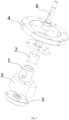
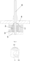
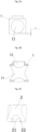
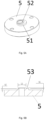
- Fig. 1 to Fig. 5B show a first embodiment of a piston limiting structure of the disclosure, the cylinder and the lower flange in some embodiments are limited by using the inner circle support.
- the piston limiting structure includes a cylinder 1, a piston 2 and a lower flange 5.
- the cylinder 1 is a cylindrical cylinder
- an axial direction of the cylinder 1 is provided with an assembling hole 12 penetrating the cylinder 1
- a rotation shaft 6 passes through the assembling hole 12.
- a peripheral surface of the cylinder 1 is provided with a piston hole 11 perpendicular to a direction of the assembling hole 12 and penetrating the cylinder 1, and a projection of the piston hole 11 along an axial direction of the piston hole itself is circular.
- the piston 2 is disposed in the piston hole 11 in a form-fit manner and is reciprocated to be slid in the piston hole 11.
- the piston 2 is matched with the piston hole 11, the piston 2 is a structure similar to a cylinder, end faces at two ends of the piston 2 are curved surface structures which are cooperated with the piston hole 11 to form a completed cylindrical surface, an axial length of the piston 2 is less than a radial size of the cylinder 1, and the piston 2 is reciprocated to be slid in the cylinder 1.
- a middle portion of the piston 2 is provided with a shaft hole 21 along an axial direction of the cylinder 1, while the piston 2 is mounted in the piston hole 11, the rotation shaft 6 passes through the assembling hole 12 of the cylinder 1 and the shaft hole 21 on the piston 2.
- a side wall of the piston 2 is provided with a thrust groove 22, and the thrust groove 22 forms a thrust surface 221 on the side wall of the piston 2.
- the thrust groove 22 is symmetrically arranged at two sides of the shaft hole 21 at a lower end of the piston 2 and the thrust surface 221 is perpendicular to an axis of the cylinder 1, the thrust groove 22 does not penetrate through two ends of the side wall of the piston 2 along an axial length of the piston 2.
- the lower flange 5 is provided with a limiting piece 52, an end face of the limiting piece 52 abuts against the thrust surface 221 to limit the piston 2 to be rotated around the axis of the piston itself.
- a cylindrical lug boss 51 is formed in the middle of an upper end face of the lower flange 5, the limiting piece 52 is integrally formed on the lug boss 51, a cross section of the limiting piece 52 is circular, a middle portion of the lower flange 5 is provided with an eccentric shaft hole, and the shaft hole successively penetrates through the limiting piece 52, the lug boss 51 and the lower flange 5.
- the piston 2 is rotated to be reciprocated relative to the limiting piece 52 in a working state, thereby it is guaranteed that the piston 2 does not collide with the limiting piece 52 in a process of a rotation reciprocating motion, while the piston 2 is reciprocated to be slid in the piston hole 11, it is satisfied: L 1 ⁇ L 2 ⁇ S
- the L1 is a length of the thrust groove 22 along the axial direction of the piston 2
- the L2 is a diameter of the limiting piece 52
- the S is a stroke of the piston 2 slid in the cylinder 1.
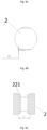
- a diameter of the limiting piece 52 is set to be less than a diameter of the lug boss 51, thus an avoidance space 53 is formed on the lug boss 51.
- the limiting piece 52 and the lug boss 51 are arranged in an internally tangent manner, and the crescent-shaped avoidance space 53 is formed on the lug boss 51.
- the length L 1 of the thrust groove 22 is effectively reduced by reducing the length L 2 of the limiting piece 52, thereby a sealing distance between the piston 2 and an inner wall of the cylinder 1 is increased correspondingly, so that a sealing effect between the piston 2 and the inner wall of the cylinder 1 is better.
- diameters of the piston 2 and the cylinder 1 are correspondingly designed to be reduced, so the mechanical power consumption of the compressor is reduced.
- h 1 is a groove depth of the thrust groove 22
- h 2 is a shortest distance from the piston hole 11 of the cylinder 1 to the end face of the cylinder 1
- h 3 is a height of the lug boss 51
- h 4 is a height of the limiting piece 52
- the height of the lug boss 51 should not be greater than the shortest distance from a bottom portion of the piston hole 11 of the cylinder 1 to the end face of the cylinder 1, namely h2 ⁇ h3, the height of the lug boss 51 does not exceed the cylinder 1 and enter the piston hole 11 to interfere with the motion of the piston 2.
- a minute clearance ⁇ exists between the upper end face of the limiting piece 52 and the thrust surface 221 of the piston 2, while the piston 2 has a tendency to auto-rotate, the thrust surface 221 of the piston 2 is inclined and contacts with the end face of the limiting piece 52, an effect of limiting the auto-rotation of the piston 2 is achieved, because the fit clearance ⁇ is small enough, an auto-rotation angle of the piston 2 is small, and the piston 2 does not collide with the cylinder sleeve 3.
- the piston 2 is jacked up to a certain small height ⁇ by the limiting piece 52, gravities of the piston 2 and the cylinder 1 need to be loaded by the limiting piece 52, the piston 2 is limited to be auto-rotated by the own gravity of the piston 2, and the limiting effect is better.
- clearances between the upper and lower side walls of the piston 2 and the cylinder 1 are adjusted by adjusting a numerical range of the ⁇ , ⁇ 0.05mm, a numerical value of the ⁇ is adjusted by finish machining, so that the assembly accuracy of the piston 2 and the cylinder 1 is higher, thereby the fit clearances between the upper and lower side walls of the piston 2 and the inner wall of the cylinder 1 are the same, the work of the piston 2 is more stable and reliable, and it is beneficial to lubrication of an oil path, so the friction power consumption is reduced.
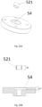
- Fig. 6 to Fig. 9 show a second embodiment of the piston limiting structure of the disclosure, in some embodiments, the piston 2 is connected with the lower flange 5 by using an inner circle support structure.
- the limiting piece 52 and the lower flange 5 are arranged as a split-type structure.
- the cylindrical lug boss 51 is formed in the middle of the upper end face of the lower flange 5, the lug boss 51 is provided with a limiting ring 521, the limiting ring 521 is a hollow cylinder structure, and an inner circle is an avoidance through hole of the rotation shaft 6, so that a lower short shaft of the rotation shaft 6 passes through the limiting ring 521.
- a lower end face of the limiting ring 521 abuts against the lug boss 51, and an upper end face abuts against the thrust surface 221 of the piston 2, thereby the auto-rotation of the piston 2 is limited.
- a diameter of the limiting ring 521 is equal to a diameter of the lug boss 51, thereby a side wall is flush with a side wall of the lug boss 51 while the limiting ring 521 is mounted on the lug boss 51, a part of a lower portion of an outer side wall of the limiting ring 521 is arranged to abut against a side wall of the assembling hole 12 of the cylinder 1, and coaxially assembled with the cylinder 1, thereby the limiting ring 521 is radially limited by the cylinder 1, and the limiting ring 521 is avoided from being radially moved in the rotation reciprocating motion process of the piston 2.
- the limiting ring 521 is rotated in a rotation process of the cylinder 1 and the piston 2, thereby the friction power consumption between the limiting ring 521 and the thrust surface 221 of the piston 2 is effectively reduced.
- the limiting ring 521 is made of a wear-resistant and anti-friction material, so the friction power consumption is further reduced. Because of the split-type structure of the limiting ring 521 and the lower flange 5, the lower flange 5 does not need to adopt an anti-friction material, the cost is reduced.
- Fig. 10 and Fig. 11 show a third embodiment of the piston limiting structure of the disclosure, in some embodiments, the lug boss 51 and the limiting piece 52 are disposed on the lower end face of the upper flange 4, the limiting piece 52 is integrally formed with the lug boss 51, the thrust surface 221 of the piston 2 is correspondingly arranged in a position of the upper side wall, the piston 2 is limited by the upper flange 4, and principles are the same as above.
- Fig. 12 and Fig. 13 show a fourth embodiment of the piston limiting structure of the disclosure, in some embodiments, the lug boss 51 and the limiting piece 52 are disposed on the lower end face of the upper flange 4, the limiting piece 52 includes a limiting ring 521, and the limiting ring 521 is arranged as the split-type structure with the upper flange 4, the thrust surface 221 of the piston 2 is correspondingly arranged in the position of the upper side wall, the piston 2 is limited by the upper flange 4, and principles are the same as above.
- Fig. 14 shows a fifth embodiment of the piston limiting structure of the disclosure
- the lug boss 51 and the limiting piece 52 are respectively arranged on the upper flange 4 and the lower flange 5
- the limiting piece 52 is integrally formed with the lug boss 51
- the thrust surface 221 of the piston 2 is correspondingly arranged at upper and lower two sides of the side wall
- the piston 2 is limited by the upper and lower flanges simultaneously, the limiting effect is better
- working principles are the same as above, and it is not repeatedly described in the implementation mode.
- Fig. 15 shows a sixth embodiment of the piston limiting structure of the disclosure
- the upper and lower flanges are both provided with the lug bosses 51
- the lug boss 51 of the upper flange 4 is provided with the limiting ring 521
- the limiting piece 52 is formed on the lug boss 51 of the lower flange 5
- the thrust surface 221 of the piston 2 is correspondingly arranged at the upper and lower two sides of the side wall
- Fig. 16 shows a seventh embodiment of the piston limiting structure of the disclosure
- the upper and lower flanges are both provided with the lug bosses 51
- the limiting piece 52 is formed on the lug boss 51 of the upper flange 4
- the lug boss 51 of the lower flange 5 is provided with the limiting ring 521
- the thrust surface 221 of the piston 2 is correspondingly arranged at the upper and lower two sides of the side wall
- Fig. 17 shows an eighth embodiment of the piston limiting structure of the disclosure, in some embodiments, the upper and lower flanges are both provided with the lug boss 51 and the limiting ring 521, the thrust surface 221 of the piston 2 is correspondingly arranged at the upper and lower two sides of the side wall, working principles are the same as above, and it is not repeatedly described here.
- Fig. 18 to Fig. 20 show a ninth embodiment of the piston limiting structure of the disclosure, in some embodiments, the lower flange 5 is connected with the cylinder 1 by using an outer circle support structure.
- a middle portion of the lower flange 5 is provided with a circular sink groove 54
- the lower end face of the cylinder 1 is provided with a cylindrical short shaft 13 protruded outwards
- the short shaft 13 is insertion-connected with the sink groove 54
- an outer wall of the short shaft 13 abuts against an inner wall of the sink groove 54, thereby an outer circle limiting structure is formed to the cylinder 1.
- a height of the short shaft 13 is less than or equal to a depth of the sink groove 54, so that the end face of the cylinder 1 abuts against the end face of the lower flange 5 while the short shaft 13 is cooperated with the sink groove 54, in some embodiments, two parties are equal to reduce the friction power consumption between the cylinder 1 and the lower flange 5.
- the cylindrical limiting piece 52 is formed in the sink groove 54 of the lower flange, and a middle portion of the limiting piece 52 is the penetrating shaft hole.
- the axial direction of the cylinder 1 is provided with the penetrating assembling hole 12, while the cylinder 1 is cooperated with the lower flange 5, the limiting piece 52 is located in the assembling hole 12, and the upper end face of the limiting piece 52 abuts against the thrust surface 221, thereby the auto-rotation of the piston 2 is limited.
- the h 1 is a groove depth of the thrust groove 22
- the h 2 is the shortest distance from the piston hole 11 of the cylinder 1 to the end face of the cylinder 1
- a minute clearance ⁇ exists between the upper end face of the limiting piece 52 and the thrust surface 221 of the piston 2, while the piston 2 has a tendency to auto-rotate, the thrust surface 221 of the piston 2 is inclined and contacts with the end face of the limiting piece 52, an effect of limiting the auto-rotation of the piston 2 is achieved, because the fit clearance ⁇ is small enough, an auto-rotation angle of the piston 2 is small, and the piston 2 does not collide with the cylinder sleeve 3.
- the piston 2 is jacked up to a certain small height ⁇ by the limiting piece 52, gravities of the piston 2 and the cylinder 1 need to be loaded by the limiting piece 52, the piston 2 is limited to be auto-rotated by the own gravity of the piston 2, and the limiting effect is better.
- a clearances between the upper side wall of the piston 2 and the cylinder 1 and a clearances between the lower side wall of the piston 2 and the cylinder 1 are adjusted by adjusting a numerical range of the ⁇ , ⁇ 0.05mm, a numerical value of the ⁇ is adjusted by finish machining, so that the assembly accuracy of the piston 2 and the cylinder 1 is higher, thereby the fit clearances between the upper and lower side walls of the piston 2 and the inner wall of the cylinder 1 are the same, the work of the piston 2 is more stable and reliable, and it is beneficial to lubrication of an oil path, so the friction power consumption is reduced.
- a limiting principle of the lower flange 5 and the piston 2 is the same as the embodiments, and it is not repeatedly described here.
- Fig. 21 , Fig. 22A and Fig. 22B show a tenth embodiment of the piston limiting structure of the disclosure
- the lower flange 5 is connected with the cylinder 1 by using the outer circle support structure, at the same time the limiting piece 52 and the lower flange 5 are arranged as the split-type structure, and the limiting piece 52 includes a structure of the limiting ring 521.
- a lower end face of the limiting ring 521 abuts against an upper end face of the sink groove 54 of the lower flange 5, and an upper end face of the limiting ring 521 abuts against the thrust surface 221 of the piston, thereby the auto-rotation of the piston 2 is limited.
- Fig. 21 , Fig. 22A and Fig. 22B show a tenth embodiment of the piston limiting structure of the disclosure
- the lower flange 5 is connected with the cylinder 1 by using the outer circle support structure, at the same time the limiting piece 52 and the lower flange 5 are
- h 6 is an axial height of the limiting ring 521
- an inner diameter of the limiting ring 521 is matched with a section diameter of the rotation shaft 6, thereby the limiting ring 521 is radially limited by the rotation shaft 6, the piston 2 is avoided from colliding with the limiting ring 521 in the reciprocating rotation motion, and an avoidance space 53 is formed between the assembling hole 12 of the cylinder 1 and the limiting ring 521, the beneficial effects are as described above.
- the outer diameter of the limiting ring 521 is the same as the diameter of the assembling hole 12, thereby the limiting ring 521 is limited by the inner wall of the assembling hole 12 of the cylinder 1.
- the piston limiting structure of the disclosure may also have other replaceable embodiments.
- the upper flange and the upper short shaft of the cylinder adopt the outer circle support structure, at the same time the limiting structure as in the ninth or tenth embodiment is adopted between the upper flange and the cylinder.
- the upper and lower flanges and the upper and lower short shafts of the cylinder all adopt the outer circle support structure, at the same time one or arbitrary combinations of the limiting structures as in the ninth and tenth embodiments are adopted.
- some embodiments of the disclosure further provide a compressor, as shown in Fig. 1
- the compressor of the embodiments of the disclosure include a rotation shaft 6, an upper flange 4, a lower flange 5, a cylinder sleeve 3, and the above piston limiting structure, the cylinder 1 is arranged in the cylinder sleeve 3, the rotation shaft 6 successively passes through the upper flange 4, the cylinder sleeve 3 and the lower flange 5.
- the compressor of some embodiments of the disclosure is based on the crosshead shoe principle, as shown in Fig.
- some embodiments of the disclosure further provide a heat exchange apparatus, and the heat exchange apparatus includes the above compressor or piston limiting structure.
- the heat exchange apparatus is an air conditioner or a refrigerator.
Landscapes
- Engineering & Computer Science (AREA)
- Mechanical Engineering (AREA)
- General Engineering & Computer Science (AREA)
- Compressor (AREA)
- Pistons, Piston Rings, And Cylinders (AREA)
Claims (15)
- Kolbenbegrenzungsstruktur, umfassend:einen Zylinder (1) mit einer Kolbenöffnung (11), die senkrecht zu einer axialen Richtung des Zylinders (1) verläuft und den Zylinder (1) durchdringt;einen Kolben (2), der in der Kolbenöffnung (11) formschlüssig angeordnet ist und in der Kolbenöffnung (11) hin und her gleitet; undeinen Flansch, der mit einem Begrenzungsstück (52) bereitgestellt ist, dadurch gekennzeichnet, dass eine Projektion der Kolbenöffnung (11) in einer Durchdringungsrichtung kreisförmig ist, wobei eine Seitenwand des Kolbens (2) mit einer Schubnut (22) bereitgestellt ist, eine Bodenfläche der Schubnut (22) eine Schubfläche (221) auf der Seitenwand des Kolbens (2) bildet, und die Schubnut (22) nicht durch zwei Enden der Seitenwand des Kolbens (2) entlang einer axialen Länge des Kolbens (2) durchdringt;wobei das Begrenzungsstück (52) an der Schubfläche (221) anliegt, um die Drehung des Kolbens (2) um eine Achse des Kolbens selbst zu begrenzen.
- Kolbenbegrenzungsstruktur nach Anspruch 1, wobei
die Schubfläche (221) senkrecht zu der axialen Richtung des Zylinders (1) verläuft. - Kolbenbegrenzungsstruktur nach Anspruch 2, wobei
der Flansch einen Vorsprung (51) umfasst, eine Endfläche des Zylinders (1) mit einer in die Kolbenöffnung (11) eindringenden Montageöffnung (12) bereitgestellt ist, der Vorsprung (51) und die Montageöffnung (12) formschlüssig ineinander gesteckt sind, sodass die Endfläche des Zylinders (1) an einer Endfläche des Flansches anliegt und der Zylinder (1) mit dem Flansch drehbar verbunden ist, das Begrenzungsstück (52) auf dem Vorsprung (51) angeordnet ist, eine Endfläche auf einer Seite des Begrenzungsstücks (52) an der Schubfläche (221) anliegt, um die Drehung des Kolbens (2) um die Achse des Kolbens selbst zu begrenzen. - Kolbenbegrenzungsstruktur nach Anspruch 3, wobei,während der Vorsprung (51) mit der Montageöffnung (12) zusammenwirkt, Folgendes erfüllt ist:
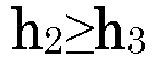 wobei h2 ein Abstand der Kolbenöffnung (11) von einem Endpunkt entlang der axialen Richtung des Zylinders (1) zu einer Endfläche an einer Seite nahe dem Endpunkt des Zylinders (1) ist und h3 eine Höhe des Vorsprungs (51) entlang der axialen Richtung des Zylinders (1) ist.
 - Kolbenbegrenzungsstruktur nach Anspruch 2, wobei
der Flansch mit einer Senknut (54) bereitgestellt ist, die Endfläche des Zylinders (1) mit einer nach außen vorstehenden kurzen Welle (13) bereitgestellt ist, die kurze Welle (13) formschlüssig mit der Senknut (54) durch Einsetzen verbunden ist, sodass die Endfläche des Zylinders (1) an der Endfläche des Flansches anliegt, und der Zylinder (1) mit dem Flansch drehverbunden ist, eine Endfläche der kurzen Welle (13) mit einer Montageöffnung (12) bereitgestellt ist, die in die Kolbenöffnung (11) eindringt, das Begrenzungsstück (52) in der Montageöffnung (12) angeordnet ist, eine Endfläche an einer Seite des Begrenzungsstücks (52) gegen die Schubfläche (221) anliegt, um die Drehung des Kolbens (2) um die Achse des Kolbens selbst zu begrenzen. - Kolbenbegrenzungsstruktur nach Anspruch 4 oder 5, wobei,
während die Endfläche an einer Seite des Begrenzungsstücks (52) an der Schubfläche (221) anliegt, Folgendes erfüllt ist: wobei h1 eine Nuttiefe der Schubnut (22) ist, h2 der Abstand der Kolbenöffnung (11) von dem Endpunkt entlang der axialen Richtung des Zylinders (1) zu der Endfläche an einer Seite nahe dem Endpunkt des Zylinders (1) ist, und h5 eine Höhe von der Endfläche an einer Seite des Begrenzungsstücks (52) zu einer Endfläche an einer Seite nahe dem Begrenzungsstück (52) des Flansches ist, ein Differenzwert von h5 und h1+h2 0-0,05 mm beträgt; oderwährend die Endfläche an einer Seite des Begrenzungsstücks (52) an der Schubfläche (221) anliegt, Folgendes erfüllt ist:
 wobei h1 eine Nuttiefe der Schubnut (22) ist, h2 der Abstand der Kolbenöffnung (11) von dem Endpunkt entlang der axialen Richtung des Zylinders (1) zu der Endfläche an einer Seite nahe dem Endpunkt des Zylinders (1) ist, und h5 eine Höhe von der Endfläche an einer Seite des Begrenzungsstücks (52) zu einer Endfläche an einer Seite nahe dem Begrenzungsstück (52) des Flansches ist, ein Differenzwert von h5 und h1+h2 0-0,05 mm beträgt.
 - Kolbenbegrenzungsstruktur nach einem der Ansprüche 1 bis 5, wobei
die Schubnut (22) in einer Position von 1/2 der axialen Richtung des Kolbens (2) angeordnet ist. - Kolbenbegrenzungsstruktur nach Anspruch 7, wobei,während der Kolben (2) hin- und herbewegt wird, um in der Kolbenöffnung (11) zu gleiten, Folgendes erfüllt ist: L1-L2≥Swobei L1 eine Länge der Drucknut (22) entlang einer axialen Richtung des Kolbens (2) ist, L2 eine Länge des Begrenzungsstücks (52) entlang der axialen Richtung des Kolbens (2) ist und S ein Hub des im Zylinder (1) gleitenden Kolbens (2) ist.
- Kolbenbegrenzungsstruktur nach einem der Ansprüche 1 bis 5, wobei das Begrenzungsstück (52) eine Kreisringstruktur umfasst.
- Kolbenbegrenzungsstruktur nach Anspruch 9, wobeidas Begrenzungsstück (52) einstückig mit dem Flansch ausgebildet ist und optional oder vorzugsweiseein Durchmesser des Begrenzungsstücks (52) kleiner als ein Durchmesser der Montageöffnung (12) ist, sodass ein Ausweichraum (53) an dem Flansch ausgebildet ist.
- Kolbenbegrenzungsstruktur nach Anspruch 9, wobeidas Begrenzungsstück (52) einen Begrenzungsring (521) umfasst, eine Endfläche an einem Ende des Begrenzungsrings (521) an dem Flansch anliegt und eine Endfläche an dem anderen Ende an der Schubfläche (221) anliegt, und optional oder vorzugsweise,ein Durchmesser des Begrenzungsrings (521) gleich dem Durchmesser der Montageöffnung (12) ist, ein Teil einer äußeren Seitenwand des Begrenzungsrings (521) in Umfangsrichtung an einer Seitenwand einer Montageöffnung (12) des Zylinders (1) anliegt, sodass der Begrenzungsring (521) in seiner radialen Bewegung begrenzt ist.
- Kolbenbegrenzungsstruktur nach Anspruch 11,
wobei der Begrenzungsring (521) aus einem verschleißfesten Material hergestellt ist. - Kolbenbegrenzungsstruktur nach einem der Ansprüche 1 bis 5, wobei
der Flansch mindestens einen oberen Flansch (4) und einen unteren Flansch (5) umfasst. - Kompressor, umfassend:eine Drehwelle (6);einen oberen Flansch (4);einen unteren Flansch (5);eine Zylinderhülse (3), die zwischen dem oberen Flansch (4) und dem unteren Flansch (5) angeordnet ist; unddie Kolbenbegrenzungsstruktur nach einem der Ansprüche 1 bis 13, wobei der Zylinder (1) in der Zylinderhülse (3) angeordnet ist, die Drehwelle (6) nacheinander durch den oberen Flansch (4), die Zylinderhülse (3) und den unteren Flansch (5) verläuft und der Zylinder (1) von der Drehwelle (6) in Drehung versetzt wird.
- Wärmetauschervorrichtung, umfassend die Kolbenbegrenzungsstruktur nach einem der Ansprüche 1 bis 13 oder den Kompressor nach Anspruch 14, wobei es sich bei der Wärmetauschervorrichtung wahlweise oder vorzugsweise um eine Klimaanlage handelt.
Applications Claiming Priority (2)
| Application Number | Priority Date | Filing Date | Title |
|---|---|---|---|
| CN201811550007.5A CN109555692B (zh) | 2018-12-18 | 2018-12-18 | 活塞限位结构、压缩机及换热设备 |
| PCT/CN2019/106868 WO2020125108A1 (zh) | 2018-12-18 | 2019-09-20 | 活塞限位结构、压缩机及换热设备 |
Publications (3)
| Publication Number | Publication Date |
|---|---|
| EP3901464A1 EP3901464A1 (de) | 2021-10-27 |
| EP3901464A4 EP3901464A4 (de) | 2022-01-12 |
| EP3901464B1 true EP3901464B1 (de) | 2024-10-30 |
Family
ID=65870299
Family Applications (1)
| Application Number | Title | Priority Date | Filing Date |
|---|---|---|---|
| EP19898512.9A Active EP3901464B1 (de) | 2018-12-18 | 2019-09-20 | Kolbenbegrenzungsstruktur, verdichter und wärmeaustauschvorrichtung |
Country Status (4)
| Country | Link |
|---|---|
| US (1) | US11976643B2 (de) |
| EP (1) | EP3901464B1 (de) |
| CN (1) | CN109555692B (de) |
| WO (1) | WO2020125108A1 (de) |
Families Citing this family (3)
| Publication number | Priority date | Publication date | Assignee | Title |
|---|---|---|---|---|
| CN108916045B (zh) * | 2018-07-18 | 2024-04-02 | 珠海格力电器股份有限公司 | 泵体组件、流体机械及换热设备 |
| CN109555692B (zh) | 2018-12-18 | 2024-07-12 | 珠海格力电器股份有限公司 | 活塞限位结构、压缩机及换热设备 |
| CN110966188B (zh) * | 2019-11-22 | 2025-05-16 | 珠海格力电器股份有限公司 | 转缸活塞压缩机的泵体结构及转缸活塞压缩机 |
Family Cites Families (17)
| Publication number | Priority date | Publication date | Assignee | Title |
|---|---|---|---|---|
| US2275240A (en) * | 1942-03-03 | wiken | ||
| US3056356A (en) * | 1958-12-18 | 1962-10-02 | Bell & Gossett Co | Rotary pump |
| US3790311A (en) | 1972-11-27 | 1974-02-05 | Gen Motors Corp | Four vane elliptical rotary air conditioning compressor |
| US4375945A (en) * | 1980-01-31 | 1983-03-08 | Kucas Industries Limited | Fuel injection pumping apparatus |
| DE3121529A1 (de) * | 1981-05-29 | 1982-12-23 | Alfred Teves Gmbh, 6000 Frankfurt | Radialkolbenmaschine, insbesondere radialkolbenpumpe |
| GB8417862D0 (en) * | 1984-07-13 | 1984-08-15 | Lucas Ind Plc | Fuel pumping apparatus |
| EP0283136B1 (de) * | 1987-03-14 | 1991-07-24 | LUCAS INDUSTRIES public limited company | Kraftstoffpumpe |
| GB8724795D0 (en) * | 1987-10-22 | 1987-11-25 | Lucas Ind Plc | Fuel injection pump |
| EP0325376A3 (de) * | 1988-01-16 | 1989-11-15 | LUCAS INDUSTRIES public limited company | Kraftstoffpumpe |
| DE4004932C2 (de) * | 1990-02-16 | 1995-04-13 | Rexroth Mannesmann Gmbh | Radialkolbenmaschine |
| JPH08312379A (ja) * | 1995-05-18 | 1996-11-26 | Zexel Corp | 燃料噴射装置 |
| CN105604937B (zh) * | 2016-02-18 | 2018-06-26 | 珠海格力节能环保制冷技术研究中心有限公司 | 流体机械和换热设备 |
| CN106065854B (zh) * | 2016-07-28 | 2017-11-24 | 珠海格力节能环保制冷技术研究中心有限公司 | 一种转缸活塞压缩机 |
| CN108799103B (zh) | 2018-07-18 | 2023-10-03 | 珠海格力节能环保制冷技术研究中心有限公司 | 泵体组件、流体机械及换热设备 |
| CN108799109B (zh) * | 2018-07-18 | 2024-04-02 | 珠海格力电器股份有限公司 | 泵体组件、流体机械及换热设备 |
| CN109555692B (zh) | 2018-12-18 | 2024-07-12 | 珠海格力电器股份有限公司 | 活塞限位结构、压缩机及换热设备 |
| CN209604248U (zh) * | 2018-12-18 | 2019-11-08 | 珠海格力电器股份有限公司 | 活塞限位结构、压缩机及换热设备 |
-
2018
- 2018-12-18 CN CN201811550007.5A patent/CN109555692B/zh active Active
-
2019
- 2019-09-20 EP EP19898512.9A patent/EP3901464B1/de active Active
- 2019-09-20 US US17/279,550 patent/US11976643B2/en active Active
- 2019-09-20 WO PCT/CN2019/106868 patent/WO2020125108A1/zh not_active Ceased
Also Published As
| Publication number | Publication date |
|---|---|
| US11976643B2 (en) | 2024-05-07 |
| CN109555692B (zh) | 2024-07-12 |
| EP3901464A4 (de) | 2022-01-12 |
| WO2020125108A1 (zh) | 2020-06-25 |
| US20210340980A1 (en) | 2021-11-04 |
| EP3901464A1 (de) | 2021-10-27 |
| CN109555692A (zh) | 2019-04-02 |
Similar Documents
| Publication | Publication Date | Title |
|---|---|---|
| EP3901464A1 (de) | Kolbenbegrenzungsstruktur, verdichter und wärmeaustauschvorrichtung | |
| EP0652373B1 (de) | Drehkolbenverdichter | |
| US9074600B2 (en) | Rotary compressor | |
| EP3901463B1 (de) | Kolbenbegrenzungsstruktur, verdichter und wärmeaustauschvorrichtung | |
| CN108799103B (zh) | 泵体组件、流体机械及换热设备 | |
| CN117145769A (zh) | 流体机械和换热设备 | |
| CN102084132A (zh) | 制冷剂压缩机 | |
| CN109555694B (zh) | 活塞限位结构、压缩机及换热设备 | |
| US12305627B2 (en) | Crankshaft, compressor, and refrigeration device | |
| JP2022518158A (ja) | ロータリーコンプレッションアセンブリ、コンプレッサー及び空調設備 | |
| CN110966188B (zh) | 转缸活塞压缩机的泵体结构及转缸活塞压缩机 | |
| CN111173801B (zh) | 双螺旋摆动液压缸 | |
| CN209604248U (zh) | 活塞限位结构、压缩机及换热设备 | |
| BR0104001B1 (pt) | arranjo de montagem de pistço para compressor hermÉtico alternativo. | |
| CN211397892U (zh) | 转缸活塞压缩机的泵体结构及转缸活塞压缩机 | |
| CN117514787A (zh) | 泵体组件、转缸泵和换热设备 | |
| CN109555695B (zh) | 活塞限位结构、压缩机及换热设备 | |
| CN110985380A (zh) | 泵体组件、流体机械及换热设备 | |
| JP5405342B2 (ja) | 液圧回転機 | |
| CN109555691B (zh) | 活塞限位结构、压缩机及换热设备 | |
| CN109555693B (zh) | 活塞限位结构、压缩机及换热设备 | |
| EP4160021B1 (de) | Pumpenkörperanordnung und strömungsmaschine | |
| CN223190631U (zh) | 泵体组件和流体机械 | |
| CN114688030B (zh) | 泵体组件和流体机械 | |
| CN209604249U (zh) | 活塞限位结构、压缩机及换热设备 |
Legal Events
| Date | Code | Title | Description |
|---|---|---|---|
| STAA | Information on the status of an ep patent application or granted ep patent |
Free format text: STATUS: THE INTERNATIONAL PUBLICATION HAS BEEN MADE |
|
| PUAI | Public reference made under article 153(3) epc to a published international application that has entered the european phase |
Free format text: ORIGINAL CODE: 0009012 |
|
| STAA | Information on the status of an ep patent application or granted ep patent |
Free format text: STATUS: REQUEST FOR EXAMINATION WAS MADE |
|
| 17P | Request for examination filed |
Effective date: 20210311 |
|
| AK | Designated contracting states |
Kind code of ref document: A1 Designated state(s): AL AT BE BG CH CY CZ DE DK EE ES FI FR GB GR HR HU IE IS IT LI LT LU LV MC MK MT NL NO PL PT RO RS SE SI SK SM TR |
|
| A4 | Supplementary search report drawn up and despatched |
Effective date: 20211210 |
|
| RIC1 | Information provided on ipc code assigned before grant |
Ipc: F04C 29/04 20060101ALI20211206BHEP Ipc: F04C 18/344 20060101AFI20211206BHEP |
|
| DAV | Request for validation of the european patent (deleted) | ||
| DAX | Request for extension of the european patent (deleted) | ||
| P01 | Opt-out of the competence of the unified patent court (upc) registered |
Effective date: 20230530 |
|
| GRAP | Despatch of communication of intention to grant a patent |
Free format text: ORIGINAL CODE: EPIDOSNIGR1 |
|
| STAA | Information on the status of an ep patent application or granted ep patent |
Free format text: STATUS: GRANT OF PATENT IS INTENDED |
|
| INTG | Intention to grant announced |
Effective date: 20240418 |
|
| GRAS | Grant fee paid |
Free format text: ORIGINAL CODE: EPIDOSNIGR3 |
|
| GRAA | (expected) grant |
Free format text: ORIGINAL CODE: 0009210 |
|
| STAA | Information on the status of an ep patent application or granted ep patent |
Free format text: STATUS: THE PATENT HAS BEEN GRANTED |
|
| AK | Designated contracting states |
Kind code of ref document: B1 Designated state(s): AL AT BE BG CH CY CZ DE DK EE ES FI FR GB GR HR HU IE IS IT LI LT LU LV MC MK MT NL NO PL PT RO RS SE SI SK SM TR |
|
| REG | Reference to a national code |
Ref country code: GB Ref legal event code: FG4D |
|
| REG | Reference to a national code |
Ref country code: CH Ref legal event code: EP |
|
| REG | Reference to a national code |
Ref country code: IE Ref legal event code: FG4D |
|
| REG | Reference to a national code |
Ref country code: DE Ref legal event code: R096 Ref document number: 602019061317 Country of ref document: DE |
|
| REG | Reference to a national code |
Ref country code: LT Ref legal event code: MG9D |
|
| REG | Reference to a national code |
Ref country code: NL Ref legal event code: MP Effective date: 20241030 |
|
| PG25 | Lapsed in a contracting state [announced via postgrant information from national office to epo] |
Ref country code: HR Free format text: LAPSE BECAUSE OF FAILURE TO SUBMIT A TRANSLATION OF THE DESCRIPTION OR TO PAY THE FEE WITHIN THE PRESCRIBED TIME-LIMIT Effective date: 20241030 Ref country code: PT Free format text: LAPSE BECAUSE OF FAILURE TO SUBMIT A TRANSLATION OF THE DESCRIPTION OR TO PAY THE FEE WITHIN THE PRESCRIBED TIME-LIMIT Effective date: 20250228 Ref country code: IS Free format text: LAPSE BECAUSE OF FAILURE TO SUBMIT A TRANSLATION OF THE DESCRIPTION OR TO PAY THE FEE WITHIN THE PRESCRIBED TIME-LIMIT Effective date: 20250228 |
|
| PG25 | Lapsed in a contracting state [announced via postgrant information from national office to epo] |
Ref country code: NL Free format text: LAPSE BECAUSE OF FAILURE TO SUBMIT A TRANSLATION OF THE DESCRIPTION OR TO PAY THE FEE WITHIN THE PRESCRIBED TIME-LIMIT Effective date: 20241030 Ref country code: FI Free format text: LAPSE BECAUSE OF FAILURE TO SUBMIT A TRANSLATION OF THE DESCRIPTION OR TO PAY THE FEE WITHIN THE PRESCRIBED TIME-LIMIT Effective date: 20241030 |
|
| REG | Reference to a national code |
Ref country code: AT Ref legal event code: MK05 Ref document number: 1737102 Country of ref document: AT Kind code of ref document: T Effective date: 20241030 |
|
| PG25 | Lapsed in a contracting state [announced via postgrant information from national office to epo] |
Ref country code: BG Free format text: LAPSE BECAUSE OF FAILURE TO SUBMIT A TRANSLATION OF THE DESCRIPTION OR TO PAY THE FEE WITHIN THE PRESCRIBED TIME-LIMIT Effective date: 20241030 |
|
| PG25 | Lapsed in a contracting state [announced via postgrant information from national office to epo] |
Ref country code: ES Free format text: LAPSE BECAUSE OF FAILURE TO SUBMIT A TRANSLATION OF THE DESCRIPTION OR TO PAY THE FEE WITHIN THE PRESCRIBED TIME-LIMIT Effective date: 20241030 |
|
| PG25 | Lapsed in a contracting state [announced via postgrant information from national office to epo] |
Ref country code: NO Free format text: LAPSE BECAUSE OF FAILURE TO SUBMIT A TRANSLATION OF THE DESCRIPTION OR TO PAY THE FEE WITHIN THE PRESCRIBED TIME-LIMIT Effective date: 20250130 |
|
| PG25 | Lapsed in a contracting state [announced via postgrant information from national office to epo] |
Ref country code: AT Free format text: LAPSE BECAUSE OF FAILURE TO SUBMIT A TRANSLATION OF THE DESCRIPTION OR TO PAY THE FEE WITHIN THE PRESCRIBED TIME-LIMIT Effective date: 20241030 Ref country code: LV Free format text: LAPSE BECAUSE OF FAILURE TO SUBMIT A TRANSLATION OF THE DESCRIPTION OR TO PAY THE FEE WITHIN THE PRESCRIBED TIME-LIMIT Effective date: 20241030 Ref country code: GR Free format text: LAPSE BECAUSE OF FAILURE TO SUBMIT A TRANSLATION OF THE DESCRIPTION OR TO PAY THE FEE WITHIN THE PRESCRIBED TIME-LIMIT Effective date: 20250131 |
|
| PG25 | Lapsed in a contracting state [announced via postgrant information from national office to epo] |
Ref country code: PL Free format text: LAPSE BECAUSE OF FAILURE TO SUBMIT A TRANSLATION OF THE DESCRIPTION OR TO PAY THE FEE WITHIN THE PRESCRIBED TIME-LIMIT Effective date: 20241030 |
|
| PG25 | Lapsed in a contracting state [announced via postgrant information from national office to epo] |
Ref country code: RS Free format text: LAPSE BECAUSE OF FAILURE TO SUBMIT A TRANSLATION OF THE DESCRIPTION OR TO PAY THE FEE WITHIN THE PRESCRIBED TIME-LIMIT Effective date: 20250130 |
|
| PG25 | Lapsed in a contracting state [announced via postgrant information from national office to epo] |
Ref country code: SM Free format text: LAPSE BECAUSE OF FAILURE TO SUBMIT A TRANSLATION OF THE DESCRIPTION OR TO PAY THE FEE WITHIN THE PRESCRIBED TIME-LIMIT Effective date: 20241030 |
|
| PG25 | Lapsed in a contracting state [announced via postgrant information from national office to epo] |
Ref country code: DK Free format text: LAPSE BECAUSE OF FAILURE TO SUBMIT A TRANSLATION OF THE DESCRIPTION OR TO PAY THE FEE WITHIN THE PRESCRIBED TIME-LIMIT Effective date: 20241030 |
|
| PG25 | Lapsed in a contracting state [announced via postgrant information from national office to epo] |
Ref country code: EE Free format text: LAPSE BECAUSE OF FAILURE TO SUBMIT A TRANSLATION OF THE DESCRIPTION OR TO PAY THE FEE WITHIN THE PRESCRIBED TIME-LIMIT Effective date: 20241030 |
|
| PG25 | Lapsed in a contracting state [announced via postgrant information from national office to epo] |
Ref country code: RO Free format text: LAPSE BECAUSE OF FAILURE TO SUBMIT A TRANSLATION OF THE DESCRIPTION OR TO PAY THE FEE WITHIN THE PRESCRIBED TIME-LIMIT Effective date: 20241030 |
|
| PG25 | Lapsed in a contracting state [announced via postgrant information from national office to epo] |
Ref country code: SK Free format text: LAPSE BECAUSE OF FAILURE TO SUBMIT A TRANSLATION OF THE DESCRIPTION OR TO PAY THE FEE WITHIN THE PRESCRIBED TIME-LIMIT Effective date: 20241030 |
|
| PG25 | Lapsed in a contracting state [announced via postgrant information from national office to epo] |
Ref country code: CZ Free format text: LAPSE BECAUSE OF FAILURE TO SUBMIT A TRANSLATION OF THE DESCRIPTION OR TO PAY THE FEE WITHIN THE PRESCRIBED TIME-LIMIT Effective date: 20241030 |
|
| PG25 | Lapsed in a contracting state [announced via postgrant information from national office to epo] |
Ref country code: IT Free format text: LAPSE BECAUSE OF FAILURE TO SUBMIT A TRANSLATION OF THE DESCRIPTION OR TO PAY THE FEE WITHIN THE PRESCRIBED TIME-LIMIT Effective date: 20241030 |
|
| REG | Reference to a national code |
Ref country code: DE Ref legal event code: R097 Ref document number: 602019061317 Country of ref document: DE |
|
| PLBE | No opposition filed within time limit |
Free format text: ORIGINAL CODE: 0009261 |
|
| STAA | Information on the status of an ep patent application or granted ep patent |
Free format text: STATUS: NO OPPOSITION FILED WITHIN TIME LIMIT |
|
| PG25 | Lapsed in a contracting state [announced via postgrant information from national office to epo] |
Ref country code: SE Free format text: LAPSE BECAUSE OF FAILURE TO SUBMIT A TRANSLATION OF THE DESCRIPTION OR TO PAY THE FEE WITHIN THE PRESCRIBED TIME-LIMIT Effective date: 20241030 |
|
| 26N | No opposition filed |
Effective date: 20250731 |
|
| PGFP | Annual fee paid to national office [announced via postgrant information from national office to epo] |
Ref country code: GB Payment date: 20250929 Year of fee payment: 7 |
|
| PGFP | Annual fee paid to national office [announced via postgrant information from national office to epo] |
Ref country code: FR Payment date: 20250929 Year of fee payment: 7 |
|
| PGFP | Annual fee paid to national office [announced via postgrant information from national office to epo] |
Ref country code: DE Payment date: 20251029 Year of fee payment: 7 |
|
| REG | Reference to a national code |
Ref country code: CH Ref legal event code: H13 Free format text: ST27 STATUS EVENT CODE: U-0-0-H10-H13 (AS PROVIDED BY THE NATIONAL OFFICE) Effective date: 20260504 |