EP3901403A1 - Shock insulating door system and method - Google Patents
Shock insulating door system and method Download PDFInfo
- Publication number
- EP3901403A1 EP3901403A1 EP21169449.2A EP21169449A EP3901403A1 EP 3901403 A1 EP3901403 A1 EP 3901403A1 EP 21169449 A EP21169449 A EP 21169449A EP 3901403 A1 EP3901403 A1 EP 3901403A1
- Authority
- EP
- European Patent Office
- Prior art keywords
- frame member
- sleeve
- door
- frame
- cover
- Prior art date
- Legal status (The legal status is an assumption and is not a legal conclusion. Google has not performed a legal analysis and makes no representation as to the accuracy of the status listed.)
- Withdrawn
Links
Images


Classifications
-
- E—FIXED CONSTRUCTIONS
- E06—DOORS, WINDOWS, SHUTTERS, OR ROLLER BLINDS IN GENERAL; LADDERS
- E06B—FIXED OR MOVABLE CLOSURES FOR OPENINGS IN BUILDINGS, VEHICLES, FENCES OR LIKE ENCLOSURES IN GENERAL, e.g. DOORS, WINDOWS, BLINDS, GATES
- E06B3/00—Window sashes, door leaves, or like elements for closing wall or like openings; Layout of fixed or moving closures, e.g. windows in wall or like openings; Features of rigidly-mounted outer frames relating to the mounting of wing frames
- E06B3/70—Door leaves
- E06B3/82—Flush doors, i.e. with completely flat surface
- E06B3/822—Flush doors, i.e. with completely flat surface with an internal foursided frame
-
- E—FIXED CONSTRUCTIONS
- E06—DOORS, WINDOWS, SHUTTERS, OR ROLLER BLINDS IN GENERAL; LADDERS
- E06B—FIXED OR MOVABLE CLOSURES FOR OPENINGS IN BUILDINGS, VEHICLES, FENCES OR LIKE ENCLOSURES IN GENERAL, e.g. DOORS, WINDOWS, BLINDS, GATES
- E06B3/00—Window sashes, door leaves, or like elements for closing wall or like openings; Layout of fixed or moving closures, e.g. windows in wall or like openings; Features of rigidly-mounted outer frames relating to the mounting of wing frames
- E06B3/30—Coverings, e.g. protecting against weather, for decorative purposes
- E06B3/301—Coverings, e.g. protecting against weather, for decorative purposes consisting of prefabricated profiled members or glass
-
- E—FIXED CONSTRUCTIONS
- E06—DOORS, WINDOWS, SHUTTERS, OR ROLLER BLINDS IN GENERAL; LADDERS
- E06B—FIXED OR MOVABLE CLOSURES FOR OPENINGS IN BUILDINGS, VEHICLES, FENCES OR LIKE ENCLOSURES IN GENERAL, e.g. DOORS, WINDOWS, BLINDS, GATES
- E06B1/00—Border constructions of openings in walls, floors, or ceilings; Frames to be rigidly mounted in such openings
- E06B1/04—Frames for doors, windows, or the like to be fixed in openings
- E06B1/34—Coverings, e.g. protecting against weather, for decorative purposes
-
- E—FIXED CONSTRUCTIONS
- E06—DOORS, WINDOWS, SHUTTERS, OR ROLLER BLINDS IN GENERAL; LADDERS
- E06B—FIXED OR MOVABLE CLOSURES FOR OPENINGS IN BUILDINGS, VEHICLES, FENCES OR LIKE ENCLOSURES IN GENERAL, e.g. DOORS, WINDOWS, BLINDS, GATES
- E06B3/00—Window sashes, door leaves, or like elements for closing wall or like openings; Layout of fixed or moving closures, e.g. windows in wall or like openings; Features of rigidly-mounted outer frames relating to the mounting of wing frames
- E06B3/04—Wing frames not characterised by the manner of movement
- E06B3/263—Frames with special provision for insulation
- E06B3/2632—Frames with special provision for insulation with arrangements reducing the heat transmission, other than an interruption in a metal section
-
- E—FIXED CONSTRUCTIONS
- E06—DOORS, WINDOWS, SHUTTERS, OR ROLLER BLINDS IN GENERAL; LADDERS
- E06B—FIXED OR MOVABLE CLOSURES FOR OPENINGS IN BUILDINGS, VEHICLES, FENCES OR LIKE ENCLOSURES IN GENERAL, e.g. DOORS, WINDOWS, BLINDS, GATES
- E06B3/00—Window sashes, door leaves, or like elements for closing wall or like openings; Layout of fixed or moving closures, e.g. windows in wall or like openings; Features of rigidly-mounted outer frames relating to the mounting of wing frames
- E06B3/30—Coverings, e.g. protecting against weather, for decorative purposes
- E06B3/301—Coverings, e.g. protecting against weather, for decorative purposes consisting of prefabricated profiled members or glass
- E06B3/305—Covering metal frames with plastic or metal profiled members
-
- E—FIXED CONSTRUCTIONS
- E06—DOORS, WINDOWS, SHUTTERS, OR ROLLER BLINDS IN GENERAL; LADDERS
- E06B—FIXED OR MOVABLE CLOSURES FOR OPENINGS IN BUILDINGS, VEHICLES, FENCES OR LIKE ENCLOSURES IN GENERAL, e.g. DOORS, WINDOWS, BLINDS, GATES
- E06B3/00—Window sashes, door leaves, or like elements for closing wall or like openings; Layout of fixed or moving closures, e.g. windows in wall or like openings; Features of rigidly-mounted outer frames relating to the mounting of wing frames
- E06B3/70—Door leaves
- E06B3/7001—Coverings therefor; Door leaves imitating traditional raised panel doors, e.g. engraved or embossed surfaces, with trim strips applied to the surfaces
-
- E—FIXED CONSTRUCTIONS
- E06—DOORS, WINDOWS, SHUTTERS, OR ROLLER BLINDS IN GENERAL; LADDERS
- E06B—FIXED OR MOVABLE CLOSURES FOR OPENINGS IN BUILDINGS, VEHICLES, FENCES OR LIKE ENCLOSURES IN GENERAL, e.g. DOORS, WINDOWS, BLINDS, GATES
- E06B3/00—Window sashes, door leaves, or like elements for closing wall or like openings; Layout of fixed or moving closures, e.g. windows in wall or like openings; Features of rigidly-mounted outer frames relating to the mounting of wing frames
- E06B3/70—Door leaves
- E06B2003/7046—Door leaves with provisions for locks, hinges or other fittings
Definitions
- the present invention relates generally to insulators and, more particularly, to a door system having an insulating and/or protective cover, such as a sleeve, to reduce the likelihood of a fire or a user being shocked by contacting the door system and/or prevent damage to a structure of the door system.
- an insulating and/or protective cover such as a sleeve
- Some door systems can sometimes spark or shock a person or object that comes into contact with the door system due to discharge of static electricity.
- Some environments such as hospitals or other healthcare facilities, may be an oxygen rich environment as a result of oxygen being used for therapeutic purposes. These environments may require precautionary measures to reduce accidents.
- ICU intensive care unit
- Some ICU applications require measures to prevent sparks from occurring due to static to reduce the likelihood of igniting the oxygen.
- some transit applications make it desirable to protect the public from electric shock that may occur when touching a train or other public transit vehicle which may be at a different electrical potential than a station door or boarding platform upon which passengers will embark. If passengers at one potential contact the public transit vehicle which is at another potential the passenger may receive an electric shock. As such, it may be desirable to have a door system that will reduce the likelihood of creating a shock or spark when brought into contact with a user or object using the door system.
- the disclosure describes a door system comprising a door including a frame forming at least a portion of a perimeter of the door and a cover configured to encase at least a portion of the frame.
- the frame comprises a first material and the cover comprises a second material.
- the disclosure describes a method of reducing electrical discharge in a door system.
- the method includes encasing at least a portion of an electrically conductive frame member of a door with an electrically insulating cover.
- the cover has a cross-sectional shape generally corresponding to a cross-sectional shape of the frame member.
- the disclosure describes an apparatus configured to encase at least a portion of a frame of a door.
- the apparatus includes an electrically insulating cover comprising a material that is different than an electrically conductive material from which the frame of the door is constructed.
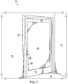
- FIG. 1 shows a door system 10 in accordance with an embodiment of the present disclosure.
- the door system 10 is installed in a wall 12.
- the floor 14 is also shown.
- the door system 10 includes a door 18 which may optionally be equipped with a handle 20.
- other hardware may be mounted on the door 18 such as a push plate and/or kick plate.
- the door may be mounted with hinges such that the door pivots open and closed or may be mounted to slide such as in one or more tracks and/or on one or more roller assemblies.
- the door 18 may be made of a frame 26 which may be made of a plurality of portions or members which, in some embodiments, are extrusions which may be aluminum, steel, or other suitable material.
- the door 18 often contains an insert 24 such as a window that spans across an opening 23 formed within the frame 26.
- the insert 24 may be made of glass, plexiglass, or other suitable material.
- the frame 26 of the door 18 surrounds and may support the window or other insert 24.
- the door 18 is mounted in a door frame 22.
- the door frame 22 is mounted in the wall 12.
- FIGS. 2A and 2B show a train platform 30.
- Some platforms 30 such as the ones shown in FIGS. 2A and 2B include platform door systems 10 which include platform doors 32.
- Other platforms 30 may be open platforms and not include platform doors 32.
- FIG. 2B shows the platform doors 32 slid to an open position exposing the train 28 and train door system 10 with train doors 36. The train doors 36 may slide to open or closed positions.
- FIG. 3 shows an example door 18, which may be similar to door 18 of Fig. 1 but mounted to slide rather than pivot, in accordance with the present disclosure.
- the door 18 has a frame 26 comprising a plurality of frame members 27 including, but not limited to, a top frame member 27a, a bottom frame member 27b, a first side frame member 27c, and an opposing second side frame member 27d. It should be appreciated that any number of frame members may be assembled together to form a frame.
- the top frame member 27a may be secured to a hanger assembly 29 to facilitate sliding of the door 18.
- One or more bottom guides 31 may be secured to the bottom frame member 27b to maintain alignment of the door 18 as it slides. For example, the bottom guides 31 may extend into a slot in a floor, a door frame, or platform.
- the door 18 includes an insert 24.
- the insert 24 may be transparent, translucent, or opaque.
- the insert 24 may be a window made of glass, plexiglass, plastic or other suitable material.
- the door 18 has a frame 26 that surrounds and supports the insert 24.
- the door 18 has a handle 20 or other hardware such as put not limited to push plates, kick plates and the like. Any suitable type of handle 20 such as a lever, knob, gripping recess, etc. may be used.
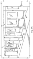
- FIGS. 4 and 5 illustrate cross-sections of a portion of a frame member of a door, for example, along the line 4-4 through the first side frame member 27c of the door 18 of Fig. 3 .
- the views of FIGS. 4 and 5 may be similarly applicable to the door 18 of FIG. 1 , the platform doors 32 of FIG. 2A , the train doors 36 of FIG. 2B , or any other suitable door such as a hospital door in an oxygen-rich medical environment.
- FIGS. 4 and 5 show the cross-sectional view of the first side frame member 27c of an embodiment of a door 18.
- the first side frame member 27c has a generally rectangular cross-sectional shape.
- the term "generally rectangular" as used herein with reference to a cross-section may refer to any shape which resembles a rectangle, including a square, even though various recesses, pockets, openings, or protrusions may extend into or from the primary surfaces of such a shape.
- the illustrated embodiment of the first side frame member 27c includes an internal wall 55a, an external wall 55b, and two lateral walls 55c, 55d extending between the internal wall and the external wall, thereby forming a generally rectangular cross-section.
- the implementation shown is generally rectangular, other implementations of the first side frame member may be any metallic shaped member. In some implementations, it is a hollow metallic shaped member which may be tubular, cylindrical, arced, triangular, or any other suitable shape.
- a frame member 27 may include an insert retaining structure 40.
- the insert retaining structure 40 serves to attach the insert 24 to the frame 26 of the door and retains the insert 24 in the door.
- the insert retaining structure 40 includes a first seal 42 and second seal 44 and an insert stop 46.
- the first seal 42 is attached to a first retaining bracket 48 and the second seal 44 is attached to a second retaining bracket 50.
- the insert stop 46 may limit movement of the insert 24 toward the frame member and may also provide a mating feature such as one or more channels 61 to mate with or otherwise receive a portion of the first and second retaining brackets 48, 50.
- the frame 26 forms two channels 61 for receiving a portion of the first and second retaining brackets 48, 50, respectively, for securing the retaining brackets to the frame 26.
- the retaining brackets 48, 50 may slide into the channel 61 and be captured by the channels or may be snap-fit into the channels. It should be appreciated that any suitable means for securing the retaining brackets 48, 50 to the frame 26 may be used such as, for example, an adhesive or a fastener.
- the first and second retaining brackets 48, 50 may be formed as a single retaining bracket or one or both retaining brackets may be omitted altogether.
- a nosing assembly 52 may be attached to the frame 26 on an opposing side from the retaining brackets 48, 50, for example, by at least one fastener 54 and a nosing assembly retaining plate 56.
- the nosing assembly 52 may provide a relatively soft surface that is configured to contact a corresponding surface of a door frame 22, as may be the case in medical environments, or of an opposing sliding door 32, 36, as may be the case in transit applications.
- the nosing assembly 52 may include a resilient member 53 and a rigid nosing assembly retaining plate 56 may aid in connecting the nosing assembly 52 to the frame 26, where use of one or more fasteners 54 alone may result in tearing or deterioration of the nosing assembly 52.
- the nosing assembly 52 may attach to the frame 26 in another suitable way.
- the nosing assembly 52 may attach to the frame 26 by an adhesive or slide in a track in the frame 26 and be captured by the track.
- the resilient member 53 of the nosing assembly 52 may itself be electrically insulating such that the nosing assembly 52 may be disposed outside of the sleeve 58 without increasing the risk of electric shock or sparking.
- components of the nosing assembly 52 which may be metallic in some embodiments, such as the fasteners 54 and nosing assembly retaining plate 56, may be disposed inside a hollow chamber of the resilient member of the nosing assembly 52 to insulate those components.
- a hole 60 may extend through an outer wall of the resilient member of the nosing assembly 52 to permit fasteners to be inserted into the hollow chamber for securing the nosing assembly 52 to a frame 26.
- one or both of the nosing assembly retaining plate 56 and fasteners 54 may be constructed of materials which are electrically insulating.
- the nosing assembly 52 may be slid into contact with an adjacent and corresponding surface of a door frame 22 or opposing door.
- the resilient member of the nosing assembly 52 may deform to absorb the impact when closing the door and/or to form a seal between the frame 26 and the adjacent surface.
- FIG. 5 shows an electrically insulating and/or protective sleeve 58 (hereinafter “sleeve”) fitted over the frame member 27c.
- sleeve an electrically insulating and/or protective sleeve 58
- FIG. 5 shows an electrically insulating and/or protective sleeve 58 (hereinafter "sleeve”) fitted over the frame member 27c.
- sleeve an electrically insulating and/or protective sleeve 58 (hereinafter “sleeve”) fitted over the frame member 27c.
- the term 'sleeve' used herein includes a one-piece member covering at least a portion of plurality of faces of a door but may also generally be considered as including any cover, including but not limited to a cover covering one face (or portion thereof) of a door or a cover comprising a plurality of separate protective and/or insulating members.
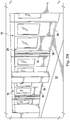
- FIG. 6 is a perspective view of the frame 26 of FIG. 5 and
- FIG. 7 is a perspective view of the sleeve 58 of FIG. 5 .
- the sleeve 58 may be rubber, plastic, polymer, or any other suitable material.
- the sleeve 58 is generally shaped to correspond to the shape of the frame member to fully or partially encase, encapsulate, conceal, surround, insulate, or otherwise cover the frame member around its cross-sectional shape. However, the sleeve 58 may not need to exactly conform to the shape of the frame member as shown by the open side 66 that may not exactly conform to the insert retaining structure 40. Additionally, the sleeve 58 may only cover a portion or all of one side (or face) of a frame member 27, two sides, three sides, four sides, all sides, etc. For example, in some embodiments, the sleeve 58 may primarily only cover the outermost surface of the frame which is most susceptible to contact with users or other surfaces.
- the sleeve 58 includes a first wall 57a which is configured to conform to the external wall 55b of the frame member 27c, and second and third walls 57b, 57c which are configured to conform to the lateral walls 55c, 55d of the frame member 27c. Additionally, the sleeve 58 may include one or more lateral projections 59a, 59b which extend inwardly toward a space defined by the second and third walls 57b, 57c of the sleeve 58. The lateral projections 59a, 59b may be oriented perpendicular to their respective wall of the sleeve or may extend at any suitable angle with respect thereto.
- one or both lateral projections 59a, 59b may conform to at least a portion of the retaining structure 40 to electrically insulate the retaining structure and/or to aid in securing the sleeve 58 to the frame 26.
- one or both lateral projections 59a, 59b may grip the frame 26 in a manner which prevents the sleeve 58 from sliding off the frame laterally.
- some or all frame members may receive a sleeve 58.
- a sleeve 58 may receive a sleeve 58.
- portions of a platform door 32 or train door 36 nearest patrons' arms and shoulders may receive a sleeve 58 while portions of the door near the platform 30 or door header may remain uncovered.
- the sleeve 58 is made of a resilient material. In instances where a frame member is made from an extruded material or otherwise has a generally consistent cross section, the sleeve 58 can be slid over the frame member.
- the fastener 54 may extend through a hole 60 in the sleeve 58. If a door is equipped with a handle 20 or other hardware, the handle 20 or other hardware may be installed after the sleeve 58 is installed and attached to the frame 26 in a non-conducting manner (such as with non-conducting fasteners or concealed structural fasteners).
- the frame 26 may include one or more retaining structures 62 that fit in one or more corresponding locking structures 64 in the sleeve 58.
- a retaining structure 62 and corresponding locking structure 64 cooperate to aid in retaining the sleeve 58 on the frame 27.
- An example of a retaining structure 62 may include a hook, a barb, a ridge, or similar protrusion extending from a surface of the frame 26.
- An example of a locking structure 64 may include a recess, a channel, a slot, or similar structure formed into the sleeve 58.
- the retaining structure 62 and locking structure 64 may each be formed of a plurality of discrete protrusions and recesses.
- the retaining structure 62 and locking structure 64 may extend the entire length of the respective sleeve 58 and frame member 27. It should be appreciated that, in some embodiments, the retaining structure 62 may be disposed on the sleeve 58 and the locking structure 64 may be disposed on the frame 26.
- the retaining structure 62 and corresponding locking structure 64 are shaped so that the sleeve 58 can slide over the frame member 27, but the retaining structure 62 and corresponding locking structure 64 will resist rotation of the sleeve 58 with respect to the frame 26 and/or translational movement of the sleeve 58 away from the frame 26 similar to how a dovetail joint and/or tongue and groove system works.
- the sleeve 58 may be slid onto a frame member longitudinally with the retaining structure 62 and locking structure 64 aligned.
- the sleeve 58 may be slid onto a frame member transverse to a longitudinal axis of the sleeve 58 through the open side 66 until one or more locking structures 64 receive one or more retaining structures 62.
- a sleeve 58 may be flexible and/or resilient to allow the opening of the open side 66 to expand to receive the frame member. This arrangement may be more suitable for embodiments in which a sleeve 58 is attached after the door has been assembled or for retrofit installations of a sleeve 58.
- a sleeve 58 may not always be preformed and then applied to a frame member 27. Rather, in some embodiments, a sleeve 58 may be formed directly on a frame member 27. For example, a sleeve may be applied to a frame member 27 by spraying a protective or insulating material onto the frame, or dipping the frame member 27 into the material, and then curing the material.
- a frame member 27 and corresponding insulating sleeve 58 will vary from one door system 10 to another. Further, each frame member 27 (e.g., top, bottom, left side, and right side members) may require different sleeves having different geometries to ensure a suitably conforming fit.
- a sleeve 58 may generally conform to a majority (e.g., contact over at least 51% of the surface area) of a corresponding shape of a member of a frame 26.
- a door system 10 may comprise four frame members 27 having four distinct cross-sectional shapes and may further comprise four sleeves 58 each having cross-sectional shapes corresponding to the frame members.
- a sleeve 58 By fitting a sleeve 58 over all or part of the frame 26 of the door, a user is less likely to be shocked and a spark is less likely to occur when the user or an object contacts or nears the door. Further, it will be understood that the sleeve 58 may be damage resistant by nature of its resiliency, however, in the event of a damaged sleeve 58, the damaged sleeve 58 can be replaced with a new sleeve 58 if needed. All or a portion of a damaged sleeve may be slid off of the frame 26 and a new sleeve may be slid into place.
- the sleeve 58 can be a cover to help protect the frame members 27 from damage and may or may not have insulating properties. In such instances, the sleeve 58 will receive the wear from contact and weathering rather than the frame 26 and the sleeve 58 can be replaced when needed or worn.
- some disassembly of the door system 10 may be needed to install a new sleeve 58.
- existing frame members 27 which may not initially have sleeves 58 may be fitted with insulating and/or protective sleeves 58. Such a retrofit may allow a formerly non-insulated door system 10 to become insulated or an unprotected door system 10 to become protected.
- existing frame members 27 may lack a retaining structure 62, such as illustrated in Fig. 4 , and a sleeve 58 may be secured to such frame members using fasteners, an adhesive, or any other suitable means.
- a sleeve 58 may have a snug conforming shape such that the sleeve 58 itself grips onto a frame member 27.
- a frame member 27 may be modified to receive a sleeve 58.
- a channel or recess may be cut into a member of a frame so that a corresponding protrusion or ridge on a sleeve 58 may be mated to the frame.
- a nosing assembly 52 is present, such a nosing assembly may be removed to allow a sleeve 58 to be installed after which the nosing assembly may be replaced.
- FIG. 8 illustrates a method 70 for reducing electrical discharge or preventing damage in a door system.
- the method may include a process 72 forming an insulative and/or protective sleeve comprising a first material that is different than a second material from which a door frame onto which the sleeve is to be installed is constructed.
- the door frame may be formed from an electrically conductive material and the sleeve may be formed from an electrically insulating material.
- the door frame may be susceptible to damage and wear and tear from contact with objects which may pass through the door and the sleeve may be formed from a material that protects the door frame from damage and may or may not be replaceable.
- Process 72 may include any method of manufacturing a sleeve made from a rubber, plastic, thermoplastic, polymer, etc. in accordance with the present disclosure such as extruding, injection molding, directly spraying, or dipping.
- Process 74 may include encasing at least a portion of at least one frame member of a door with the sleeve. Encasing the frame member may include a process 76 of sliding the sleeve onto the frame member and a process 78 of securing the sleeve to the frame member.
- the sleeve may be secured to the frame member by any suitable means such as, but not limited to, engagement of corresponding mating features of the sleeve and the frame member (e.g., a ridge and a channel), an adhesive, one or more fasteners, gripping the frame member with lateral protrusions of the sleeve, etc.
- suitable means such as, but not limited to, engagement of corresponding mating features of the sleeve and the frame member (e.g., a ridge and a channel), an adhesive, one or more fasteners, gripping the frame member with lateral protrusions of the sleeve, etc.
- Some embodiments of the method 70 may include removing hardware such as door handles or nosing assemblies prior to the process 74 of encasing the frame member and may include reinstalling the hardware after process 74.
- Reinstalling the hardware may include cutting, drilling, or otherwise forming openings through the sleeve to allow the hardware components to be reinstalled in their original locations.
- a door system comprises a door including a frame forming at least a portion of a perimeter of the door, wherein the frame comprises a first material; and a cover configured to encase at least a portion of the frame, wherein the cover comprises a second material.
- the first material of said door system may be made of metal and the second material may be non-metallic.
- the second material can be resilient and the cover may be configured to shield at least a portion of the frame from damage.
- the second material may also comprise at least one of a plastic, a rubber, a fiberglass, or a polymer.
- the frame of the said door may comprise a plurality of frame members, and the cover may be a sleeve having a cross-sectional shape configured to conform to at least a majority of a cross-sectional shape of at least a first frame member of the plurality of frame members.
- This first frame member and the sleeve may be each formed as an extrusion having a constant cross-sectional shape along its respective length.
- One of the first frame member or the sleeve may also comprise a protrusion extending along its length.
- the other of the first frame member or the sleeve may comprise a corresponding recess extending along its length, wherein the recess may be configured to receive at least a portion of the protrusion to secure the sleeve on the first frame member.
- the first frame member may have a generally rectangular cross-sectional shape comprising an internal wall configured to face an opposing second frame member of the frame, an external wall opposite the internal wall and configured to face outward from the door, and two lateral walls extending between the internal wall and the external wall.
- the sleeve may have a generally corresponding rectangular cross-sectional shape which may comprise a first wall of the sleeve configured to cover an external surface of the external wall of the first frame member, a second wall and a third wall of the sleeve extending from the first wall, each of the second and third walls configured to cover a respective one of the lateral walls of the first frame member, and an open side opposite the first wall.
- the open side of the sleeve can comprise at least one lateral projection extending inward to a space defined between the second and third walls of the sleeve.
- the at least one lateral projection of such door system may further comprise opposing lateral projections configured to at least partially conceal an external surface of the internal wall of the first frame member.
- Such door system may further comprise a retaining structure configured to support an insert of the door extending across an opening defined by the plurality of frame members, wherein the opposing lateral projections are preferably configured to cover at least a portion of the retaining structure.
- the said door system can also be configured such that the second wall preferably has a length exceeding a length of a respective one of the two lateral walls of the first frame member such that the second wall preferably extends a distance past the internal wall of the first frame member.
- the sleeve of the door system as described above can preferably further be configured to be received on the first frame member by sliding the sleeve over the first frame member longitudinally from a longitudinal end of the first frame member with the protrusion and recess generally aligned.
- the sleeve of the door system as described above can alternatively preferably further be configured to be received on the first frame member by sliding the sleeve over the first frame member through an open side of the sleeve in a direction transverse to a longitudinal axis of the first frame member until the protrusion is received in the recess.
- the door system as described above can also alternatively be configured so that the one of the first frame member or the sleeve preferably comprises a second protrusion on a side opposite the protrusion and wherein the other of the first frame member or the sleeve preferably comprises a corresponding second recess, wherein the second recess may preferably be configured to receive at least a portion of the second protrusion to secure the sleeve on the first frame member.
- a method of reducing electrical discharge in a door system comprises the step of encasing at least a portion of an electrically conductive frame member of a door with an electrically insulating cover, wherein the cover has a cross-sectional shape generally corresponding to a cross-sectional shape of the frame member.
- the portion of the frame member of the door may preferably be encased by sliding the cover onto the frame member and by securing the cover to the frame member.
- the cover is preferably secured to the frame member by engagement of corresponding mating features of the cover and the frame member.
- An apparatus is configured to encase at least a portion of a frame of a door.
- the apparatus comprises an electrically insulating sleeve comprising a material that is different than an electrically conductive material from which the frame of the door is constructed.
Landscapes
- Engineering & Computer Science (AREA)
- Civil Engineering (AREA)
- Structural Engineering (AREA)
- Physics & Mathematics (AREA)
- Thermal Sciences (AREA)
- Wing Frames And Configurations (AREA)
- Platform Screen Doors And Railroad Systems (AREA)
- Elimination Of Static Electricity (AREA)
- Securing Of Glass Panes Or The Like (AREA)
Applications Claiming Priority (1)
| Application Number | Priority Date | Filing Date | Title |
|---|---|---|---|
| US202063012476P | 2020-04-20 | 2020-04-20 |
Publications (1)
| Publication Number | Publication Date |
|---|---|
| EP3901403A1 true EP3901403A1 (en) | 2021-10-27 |
Family
ID=75625373
Family Applications (1)
| Application Number | Title | Priority Date | Filing Date |
|---|---|---|---|
| EP21169449.2A Withdrawn EP3901403A1 (en) | 2020-04-20 | 2021-04-20 | Shock insulating door system and method |
Country Status (3)
| Country | Link |
|---|---|
| US (2) | US11808081B2 (https=) |
| EP (1) | EP3901403A1 (https=) |
| JP (1) | JP2021173160A (https=) |
Families Citing this family (2)
| Publication number | Priority date | Publication date | Assignee | Title |
|---|---|---|---|---|
| WO2019232541A1 (en) * | 2018-06-01 | 2019-12-05 | Splitt Enterprises Llc | Mounting bracket |
| CN114030489B (zh) * | 2021-11-18 | 2023-03-03 | 宁波中车时代传感技术有限公司 | 一种具有绝缘功能的站台门 |
Citations (5)
| Publication number | Priority date | Publication date | Assignee | Title |
|---|---|---|---|---|
| FR2298676A1 (fr) * | 1975-01-22 | 1976-08-20 | Vuillaume Paul | Ouverture a cadres coulissants et profiles de structure la composant |
| GB2078285A (en) * | 1980-06-19 | 1982-01-06 | Brunsdon Alan Francis | Window frame member |
| KR200448617Y1 (ko) * | 2008-10-31 | 2010-05-03 | 주식회사남선알미늄 | 복합창 구조 |
| US20150159422A1 (en) * | 2011-12-09 | 2015-06-11 | 3M Innovative Properties Company | Window frame wrapping system |
| US10208526B1 (en) * | 2016-01-27 | 2019-02-19 | Richard E. Martin | Decorative cover for commercial window frames |
Family Cites Families (94)
| Publication number | Priority date | Publication date | Assignee | Title |
|---|---|---|---|---|
| US1287622A (en) * | 1916-03-13 | 1918-12-17 | Thomas F Berrill | Door and window construction. |
| US1301930A (en) * | 1917-02-26 | 1919-04-29 | Solar Metal Products Company | Metal door or window frame structure. |
| US1620933A (en) * | 1926-03-01 | 1927-03-15 | Joseph T Wilcox | Casing protector |
| US2755895A (en) * | 1952-11-13 | 1956-07-24 | Kewanee Mfg Company | Doorframe |
| US2837787A (en) * | 1954-03-12 | 1958-06-10 | Carl C Wright | Protective and decorative device for door jambs and the like |
| US3370383A (en) * | 1965-02-03 | 1968-02-27 | Ador Corp | Reversible sliding door and window construction |
| US3391509A (en) * | 1966-11-03 | 1968-07-09 | Albert A. Fruman | Drywall edge construction and finishing channel |
| US3591985A (en) * | 1969-09-30 | 1971-07-13 | Gary J Coppins | Plastic-sheathed door frame |
| US3757473A (en) * | 1972-01-03 | 1973-09-11 | Permaneer Corp | Integral prefinished wood base door and split jamb assembly |
| US3924373A (en) * | 1974-05-22 | 1975-12-09 | United States Gypsum Co | Combination screw aligning and frame reinforcing brace |
| US4107897A (en) * | 1975-02-06 | 1978-08-22 | Kessler Products Co., Inc. | Snap-in plastic frame for panels |
| SE7706076L (sv) * | 1977-05-24 | 1978-11-25 | Schoultz Sven | Kantskena for hyllskivor och dylikt |
| USRE31536E (en) * | 1978-07-17 | 1984-03-13 | Metal cladded window products | |
| US4207707A (en) * | 1978-07-17 | 1980-06-17 | Lancer Corporation | Metal cladded window products |
| US4223494A (en) * | 1979-04-09 | 1980-09-23 | United States Gypsum Company | Doorframe assembly for partition wall construction |
| US4281480A (en) * | 1979-06-21 | 1981-08-04 | U.S. Gypsum Company | Doorframe construction |
| US4505080A (en) * | 1980-07-24 | 1985-03-19 | Sailor Vernon R | Door or window frame assembly |
| US4467576A (en) * | 1982-11-10 | 1984-08-28 | Buergers Helmut | Outer frame for facing a wall opening |
| US4513549A (en) * | 1983-03-25 | 1985-04-30 | United States Gypsum Company | Pre-mitered doorframe assembly for partition wall construction |
| IL69506A (en) * | 1983-08-16 | 1987-02-27 | Rav Bariach Ltd | Method for facing wooden door frames |
| DK157144C (da) * | 1986-07-03 | 1990-04-16 | Rasmussen Kann Ind As | Vindueselement |
| US4768320A (en) * | 1986-10-10 | 1988-09-06 | Weller Rick W | Door frame guard |
| US5454198A (en) * | 1991-04-29 | 1995-10-03 | Aulson; Alan P. | Lead-base paint control arrangement for frame members subject to heavy wear |
| US5249399A (en) * | 1991-04-29 | 1993-10-05 | Aulson Alan P | Lead-base paint painted woodwork control arrangement |
| US5222345A (en) * | 1991-08-13 | 1993-06-29 | Riley Thomas J | Protective covering for window sills and frames |
| US5182880A (en) * | 1991-11-18 | 1993-02-02 | New Morning Windows, Inc. | Door frame cladding apparatus |
| US5203130A (en) * | 1991-11-26 | 1993-04-20 | Freelove James W | Door frame shield |
| US5339583A (en) * | 1992-01-17 | 1994-08-23 | Pella Corporation | Window sash and method of constructing same |
| US5214880A (en) * | 1992-04-03 | 1993-06-01 | Emco Enterprises, Inc. | Door edge construction |
| US5729942A (en) * | 1996-04-10 | 1998-03-24 | Moore, Jr.; Franklin | Wall assembly of foam blocks with internal concrete grid and integral window frame |
| US5669192A (en) * | 1996-04-26 | 1997-09-23 | Benjamin Obdyke Incorporated | Cladding for door and window frames |
| US5799443A (en) * | 1996-06-13 | 1998-09-01 | Koeniguer; Charles D. | Door and door frame protector assembly |
| US6343438B1 (en) * | 1996-07-03 | 2002-02-05 | Bay Industries, Inc. | Door frame and kit |
| US5758458A (en) * | 1996-08-01 | 1998-06-02 | Ridge; Jimmy D. | Wood and vinyl hybrid residential door frame |
| US5815998A (en) * | 1996-08-15 | 1998-10-06 | Wamsher; Lawrence G. | Door jamb protector apparatus |
| US5737878A (en) * | 1996-09-05 | 1998-04-14 | Raulerson; David B. | Door frame guard device |
| US5775045A (en) * | 1997-01-18 | 1998-07-07 | Hill; Donald L. | Door frame guard |
| US5916077A (en) * | 1997-02-20 | 1999-06-29 | Chuan Mau Products, Ltd. | Composite fire-proof, heat-barrier door |
| US5987843A (en) * | 1997-11-26 | 1999-11-23 | Canfield; Fred C. | Composite door frame and method of making the same |
| US6125605A (en) * | 1998-04-03 | 2000-10-03 | Young; Robert H. | Cladding for trim members used on buildings |
| US6357187B1 (en) * | 1998-09-28 | 2002-03-19 | Matthew K. Haldeman | Door frame protector |
| US8091299B2 (en) * | 1998-12-31 | 2012-01-10 | Marquis, Inc. | Entryway protector |
| US6216395B1 (en) * | 1999-02-08 | 2001-04-17 | Donald R. Kelly | Threshold protective cover |
| US20050155291A1 (en) * | 2000-01-24 | 2005-07-21 | Jambskins, Inc. | Adjustably resilient jamb protection system |
| US6684572B2 (en) * | 2000-01-24 | 2004-02-03 | Jambskins, Inc. | Jamb protection system |
| DE10017945A1 (de) * | 2000-04-11 | 2001-10-18 | Bernd Schweikart | Verfahren zum Herstellen eines Fensterprofils |
| US6826877B1 (en) * | 2000-08-11 | 2004-12-07 | Jeffrey J. Stradel | Door frame guard |
| US6526708B1 (en) * | 2001-08-30 | 2003-03-04 | Briane L. Hartley | Door frame guard |
| US20090000224A1 (en) * | 2002-02-07 | 2009-01-01 | Bay Industries, Inc. | Pultruded door frame |
| US20080178541A1 (en) * | 2002-02-07 | 2008-07-31 | Lawrence Frank Kerscher | Door jamb components, subassemblies, and assemblies |
| US20050097839A1 (en) * | 2002-02-07 | 2005-05-12 | Bay Industries, Inc | Door frame |
| AU2003248852A1 (en) * | 2002-07-09 | 2004-01-23 | Custom Millworking, Inc. | Door jamb protector |
| US6703102B1 (en) * | 2002-08-06 | 2004-03-09 | James B. Humphrey, Jr. | Door jamb protection device |
| US20040088933A1 (en) * | 2002-11-08 | 2004-05-13 | Mayes Timothy Joe | Trim guard |
| US20040221527A1 (en) * | 2003-02-10 | 2004-11-11 | Sykora Sean R. | Door frame protector |
| US20050055962A1 (en) * | 2003-09-11 | 2005-03-17 | Mcelroy Mike S. | Supplemental door trim |
| US7886501B2 (en) * | 2003-10-14 | 2011-02-15 | Construction Specialties, Inc. | Door edge construction |
| US7654046B2 (en) * | 2004-03-17 | 2010-02-02 | Reese Enterprises, Inc. | Door frame with unitary head flashing, nailing fin, and tear-away construction cover |
| TW200535320A (en) * | 2004-03-17 | 2005-11-01 | Premdor International Inc | Wood-plastic composite door jamb and brickmold, and method of making same |
| US20060005470A1 (en) * | 2004-05-21 | 2006-01-12 | Pat Mullen | Door threshold protective cover |
| US20060059800A1 (en) * | 2004-08-12 | 2006-03-23 | Minter Mearl J | Curved window assembly and method of formation |
| US20090211183A1 (en) * | 2004-12-17 | 2009-08-27 | Bay Industries Inc. | Strengthened extruded aluminum door frame structures |
| US20090211184A1 (en) * | 2004-12-17 | 2009-08-27 | Bay Industires Inc. | Fins and kerfs in extruded aluminum door frames and frame elements |
| TW200722606A (en) * | 2005-07-14 | 2007-06-16 | Kaba Gilgen Ag | Sliding door construction for platforms and method for assembly thereof |
| US20070137120A1 (en) * | 2005-12-16 | 2007-06-21 | Christopher Raymond | Cladding for door and window frames |
| US7971400B2 (en) * | 2007-01-16 | 2011-07-05 | Bay Industries, Inc. | Door frames and coverings |
| US20080256881A1 (en) * | 2007-04-20 | 2008-10-23 | Sonoco Development, Inc. | Door frame edge protector |
| US20080256897A1 (en) * | 2007-04-20 | 2008-10-23 | Sonoco Development, Inc. | Door edge protector |
| US8281532B2 (en) * | 2007-04-24 | 2012-10-09 | Pn Ii, Inc. | Edge cladding |
| US20090064609A1 (en) * | 2007-09-11 | 2009-03-12 | Tianhong Ouyang | Retrofit system for doors, windows and framed openings |
| CA2640315C (en) * | 2008-10-03 | 2012-07-17 | Kohltech International, Ltd. | A fenestration covering and fenestration assembly |
| US20100251642A1 (en) * | 2009-04-03 | 2010-10-07 | Ron Erickson | Frame casing kit |
| US8534012B2 (en) * | 2009-06-30 | 2013-09-17 | Woodcelli Enterprises, LLC | Trim molding structure |
| US7861465B1 (en) * | 2009-09-21 | 2011-01-04 | Joseph Christ | Flexible door guard |
| US10202796B2 (en) * | 2009-10-05 | 2019-02-12 | R Value, Inc. | Press fit storm window system |
| US8490350B1 (en) * | 2009-12-09 | 2013-07-23 | Troy Anthony Greely | Exterior window and door trim |
| US8881492B2 (en) * | 2012-02-29 | 2014-11-11 | Gary C. Piccirillo | Window buck having right trapezoid cross-section |
| US9470028B2 (en) * | 2013-05-06 | 2016-10-18 | Gregory A. Header | Sliding door assembly |
| US9273480B2 (en) * | 2013-11-30 | 2016-03-01 | Michel R. Larochelle | Method and apparatus for repairing and sealing door and window jambs, frames, and exterior trim |
| US20160130826A1 (en) * | 2013-11-30 | 2016-05-12 | Michel R. Larochelle | Method and apparatus for repairing and sealing door and window jambs, frames, thresholds, and exterior trim |
| US9598892B2 (en) * | 2014-09-15 | 2017-03-21 | Gregory Header | Quick release cladding system for door, window, sloped and vertical glazing systems frames, and the like |
| JP6591902B2 (ja) * | 2016-01-25 | 2019-10-16 | Ykk Ap株式会社 | 扉体及び建具 |
| JP6576263B2 (ja) * | 2016-02-16 | 2019-09-18 | Ykk Ap株式会社 | 建具 |
| WO2018026654A1 (en) * | 2016-08-04 | 2018-02-08 | Aadg, Inc. | Insulated reinforced door panel and door frame with thermal break |
| CA2988888C (en) * | 2016-12-16 | 2019-10-15 | Pella Corporation | Reserve cladding biasing |
| US20180266167A1 (en) * | 2017-03-16 | 2018-09-20 | Frank Novak & Sons, Inc. | Door frame protector |
| US10589945B2 (en) * | 2017-08-09 | 2020-03-17 | Ernest Martell | Protective panel for shielding a dock pad |
| JP6914805B2 (ja) * | 2017-10-25 | 2021-08-04 | Ykk Ap株式会社 | 建具 |
| CN207553874U (zh) * | 2017-11-24 | 2018-06-29 | 王书泉 | 一种节能安全复合窗 |
| US20200165864A1 (en) * | 2018-11-26 | 2020-05-28 | Guy MacDonald | Shield for mobile home door |
| FR3091717B1 (fr) * | 2019-01-11 | 2021-01-29 | Imaform | Structure d’habillage pour porte |
| US20200284086A1 (en) * | 2019-03-06 | 2020-09-10 | Bruce VOLPE | Door frame guard |
| US10550631B2 (en) * | 2019-03-15 | 2020-02-04 | Nan Ya Plastics Corporation | Closure fire rated frame extrusion component and a method of making the same |
| TWM596257U (zh) * | 2020-02-07 | 2020-06-01 | 可文山 | 模組化玻璃門 |
-
2021
- 2021-04-16 US US17/233,160 patent/US11808081B2/en active Active
- 2021-04-20 JP JP2021070732A patent/JP2021173160A/ja active Pending
- 2021-04-20 EP EP21169449.2A patent/EP3901403A1/en not_active Withdrawn
-
2023
- 2023-10-10 US US18/483,775 patent/US12421786B2/en active Active
Patent Citations (5)
| Publication number | Priority date | Publication date | Assignee | Title |
|---|---|---|---|---|
| FR2298676A1 (fr) * | 1975-01-22 | 1976-08-20 | Vuillaume Paul | Ouverture a cadres coulissants et profiles de structure la composant |
| GB2078285A (en) * | 1980-06-19 | 1982-01-06 | Brunsdon Alan Francis | Window frame member |
| KR200448617Y1 (ko) * | 2008-10-31 | 2010-05-03 | 주식회사남선알미늄 | 복합창 구조 |
| US20150159422A1 (en) * | 2011-12-09 | 2015-06-11 | 3M Innovative Properties Company | Window frame wrapping system |
| US10208526B1 (en) * | 2016-01-27 | 2019-02-19 | Richard E. Martin | Decorative cover for commercial window frames |
Also Published As
| Publication number | Publication date |
|---|---|
| JP2021173160A (ja) | 2021-11-01 |
| US20240035332A1 (en) | 2024-02-01 |
| US11808081B2 (en) | 2023-11-07 |
| US20210324677A1 (en) | 2021-10-21 |
| US12421786B2 (en) | 2025-09-23 |
Similar Documents
| Publication | Publication Date | Title |
|---|---|---|
| US12421786B2 (en) | Shock insulating door system and method | |
| CA2689900C (en) | Sliding door assembly allowing for varying performance and threshold heights | |
| CA2004357C (en) | Thermally insulated aluminum door frame | |
| US20120124923A1 (en) | Movable partition systems including intumescent material and methods of installing such movable partition systems | |
| US6533251B1 (en) | Modular railing system | |
| US5630459A (en) | Shield apparatus and method for sectional door hinge | |
| WO1995016096A1 (en) | Mounting for movable members | |
| US20150300387A1 (en) | Protective clips for movable partitions and related methods | |
| US6840300B2 (en) | Track guard for a sectional overhead door assembly | |
| GB2072248A (en) | Roller shutters | |
| US9470024B2 (en) | Closure assemblies for movable partitions, movable partition systems including closure assemblies and related methods | |
| KR101578393B1 (ko) | 기밀성과 단열성을 향상시킨 자동문 하부의 조립구조 | |
| US11220857B2 (en) | Fire-resistant sliding door system | |
| KR101600585B1 (ko) | 단열 도어조립체 | |
| US20140190091A1 (en) | Movable partitions, panel assemblies, and methods of attaching protective clips to panels of movable partitions | |
| KR102399626B1 (ko) | 손끼임 방지 기능을 갖는 여닫이식 도어시스템 | |
| JP2006022589A (ja) | 樹脂サッシ | |
| KR200332674Y1 (ko) | 승강기도어끼임방지장치 | |
| KR20220014216A (ko) | 단열 성능이 구비된 방화 창호 | |
| EP1681429A1 (en) | Door | |
| US20250230705A1 (en) | Sealing bracket | |
| JP2003033444A (ja) | エレベータ乗降口における防煙装置 | |
| KR20110039668A (ko) | 화장실 문의 경첩부 가림장치 | |
| WO2024130370A1 (pt) | Porta antiesmagamento, borda flexível, componente rígido, folha de porta e sistema de porta antiesmagamento | |
| JP2005163404A (ja) | 引き違い窓枠用サッシ |
Legal Events
| Date | Code | Title | Description |
|---|---|---|---|
| PUAI | Public reference made under article 153(3) epc to a published international application that has entered the european phase |
Free format text: ORIGINAL CODE: 0009012 |
|
| STAA | Information on the status of an ep patent application or granted ep patent |
Free format text: STATUS: THE APPLICATION HAS BEEN PUBLISHED |
|
| AK | Designated contracting states |
Kind code of ref document: A1 Designated state(s): AL AT BE BG CH CY CZ DE DK EE ES FI FR GB GR HR HU IE IS IT LI LT LU LV MC MK MT NL NO PL PT RO RS SE SI SK SM TR |
|
| B565 | Issuance of search results under rule 164(2) epc |
Effective date: 20210908 |
|
| STAA | Information on the status of an ep patent application or granted ep patent |
Free format text: STATUS: REQUEST FOR EXAMINATION WAS MADE |
|
| 17P | Request for examination filed |
Effective date: 20220421 |
|
| RBV | Designated contracting states (corrected) |
Designated state(s): AL AT BE BG CH CY CZ DE DK EE ES FI FR GB GR HR HU IE IS IT LI LT LU LV MC MK MT NL NO PL PT RO RS SE SI SK SM TR |
|
| STAA | Information on the status of an ep patent application or granted ep patent |
Free format text: STATUS: EXAMINATION IS IN PROGRESS |
|
| 17Q | First examination report despatched |
Effective date: 20230613 |
|
| RIN1 | Information on inventor provided before grant (corrected) |
Inventor name: ROMERO, FEDERICO |
|
| STAA | Information on the status of an ep patent application or granted ep patent |
Free format text: STATUS: THE APPLICATION IS DEEMED TO BE WITHDRAWN |
|
| 18D | Application deemed to be withdrawn |
Effective date: 20251101 |