EP3900935A1 - Flüssigkeitsausstosskopf - Google Patents
Flüssigkeitsausstosskopf Download PDFInfo
- Publication number
- EP3900935A1 EP3900935A1 EP21169283.5A EP21169283A EP3900935A1 EP 3900935 A1 EP3900935 A1 EP 3900935A1 EP 21169283 A EP21169283 A EP 21169283A EP 3900935 A1 EP3900935 A1 EP 3900935A1
- Authority
- EP
- European Patent Office
- Prior art keywords
- upstream
- manifold
- parts
- inlet
- discharge head
- Prior art date
- Legal status (The legal status is an assumption and is not a legal conclusion. Google has not performed a legal analysis and makes no representation as to the accuracy of the status listed.)
- Withdrawn
Links
Images


Classifications
-
- B—PERFORMING OPERATIONS; TRANSPORTING
- B41—PRINTING; LINING MACHINES; TYPEWRITERS; STAMPS
- B41J—TYPEWRITERS; SELECTIVE PRINTING MECHANISMS, i.e. MECHANISMS PRINTING OTHERWISE THAN FROM A FORME; CORRECTION OF TYPOGRAPHICAL ERRORS
- B41J2/00—Typewriters or selective printing mechanisms characterised by the printing or marking process for which they are designed
- B41J2/005—Typewriters or selective printing mechanisms characterised by the printing or marking process for which they are designed characterised by bringing liquid or particles selectively into contact with a printing material
- B41J2/01—Ink jet
- B41J2/135—Nozzles
- B41J2/14—Structure thereof only for on-demand ink jet heads
- B41J2/14201—Structure of print heads with piezoelectric elements
- B41J2/14233—Structure of print heads with piezoelectric elements of film type, deformed by bending and disposed on a diaphragm
-
- B—PERFORMING OPERATIONS; TRANSPORTING
- B41—PRINTING; LINING MACHINES; TYPEWRITERS; STAMPS
- B41J—TYPEWRITERS; SELECTIVE PRINTING MECHANISMS, i.e. MECHANISMS PRINTING OTHERWISE THAN FROM A FORME; CORRECTION OF TYPOGRAPHICAL ERRORS
- B41J2/00—Typewriters or selective printing mechanisms characterised by the printing or marking process for which they are designed
- B41J2/005—Typewriters or selective printing mechanisms characterised by the printing or marking process for which they are designed characterised by bringing liquid or particles selectively into contact with a printing material
- B41J2/01—Ink jet
- B41J2/135—Nozzles
- B41J2/14—Structure thereof only for on-demand ink jet heads
- B41J2/14201—Structure of print heads with piezoelectric elements
-
- B—PERFORMING OPERATIONS; TRANSPORTING
- B41—PRINTING; LINING MACHINES; TYPEWRITERS; STAMPS
- B41J—TYPEWRITERS; SELECTIVE PRINTING MECHANISMS, i.e. MECHANISMS PRINTING OTHERWISE THAN FROM A FORME; CORRECTION OF TYPOGRAPHICAL ERRORS
- B41J2/00—Typewriters or selective printing mechanisms characterised by the printing or marking process for which they are designed
- B41J2/005—Typewriters or selective printing mechanisms characterised by the printing or marking process for which they are designed characterised by bringing liquid or particles selectively into contact with a printing material
- B41J2/01—Ink jet
-
- B—PERFORMING OPERATIONS; TRANSPORTING
- B41—PRINTING; LINING MACHINES; TYPEWRITERS; STAMPS
- B41J—TYPEWRITERS; SELECTIVE PRINTING MECHANISMS, i.e. MECHANISMS PRINTING OTHERWISE THAN FROM A FORME; CORRECTION OF TYPOGRAPHICAL ERRORS
- B41J2/00—Typewriters or selective printing mechanisms characterised by the printing or marking process for which they are designed
- B41J2/005—Typewriters or selective printing mechanisms characterised by the printing or marking process for which they are designed characterised by bringing liquid or particles selectively into contact with a printing material
- B41J2/01—Ink jet
- B41J2/135—Nozzles
- B41J2/165—Prevention or detection of nozzle clogging, e.g. cleaning, capping or moistening for nozzles
- B41J2/16517—Cleaning of print head nozzles
- B41J2/16552—Cleaning of print head nozzles using cleaning fluids
-
- B—PERFORMING OPERATIONS; TRANSPORTING
- B41—PRINTING; LINING MACHINES; TYPEWRITERS; STAMPS
- B41J—TYPEWRITERS; SELECTIVE PRINTING MECHANISMS, i.e. MECHANISMS PRINTING OTHERWISE THAN FROM A FORME; CORRECTION OF TYPOGRAPHICAL ERRORS
- B41J2/00—Typewriters or selective printing mechanisms characterised by the printing or marking process for which they are designed
- B41J2/005—Typewriters or selective printing mechanisms characterised by the printing or marking process for which they are designed characterised by bringing liquid or particles selectively into contact with a printing material
- B41J2/01—Ink jet
- B41J2/17—Ink jet characterised by ink handling
- B41J2/175—Ink supply systems ; Circuit parts therefor
- B41J2/17503—Ink cartridges
-
- B—PERFORMING OPERATIONS; TRANSPORTING
- B41—PRINTING; LINING MACHINES; TYPEWRITERS; STAMPS
- B41J—TYPEWRITERS; SELECTIVE PRINTING MECHANISMS, i.e. MECHANISMS PRINTING OTHERWISE THAN FROM A FORME; CORRECTION OF TYPOGRAPHICAL ERRORS
- B41J2/00—Typewriters or selective printing mechanisms characterised by the printing or marking process for which they are designed
- B41J2/005—Typewriters or selective printing mechanisms characterised by the printing or marking process for which they are designed characterised by bringing liquid or particles selectively into contact with a printing material
- B41J2/01—Ink jet
- B41J2/17—Ink jet characterised by ink handling
- B41J2/175—Ink supply systems ; Circuit parts therefor
- B41J2/17596—Ink pumps, ink valves
-
- B—PERFORMING OPERATIONS; TRANSPORTING
- B41—PRINTING; LINING MACHINES; TYPEWRITERS; STAMPS
- B41J—TYPEWRITERS; SELECTIVE PRINTING MECHANISMS, i.e. MECHANISMS PRINTING OTHERWISE THAN FROM A FORME; CORRECTION OF TYPOGRAPHICAL ERRORS
- B41J2/00—Typewriters or selective printing mechanisms characterised by the printing or marking process for which they are designed
- B41J2/005—Typewriters or selective printing mechanisms characterised by the printing or marking process for which they are designed characterised by bringing liquid or particles selectively into contact with a printing material
- B41J2/01—Ink jet
- B41J2/135—Nozzles
- B41J2/14—Structure thereof only for on-demand ink jet heads
- B41J2/14201—Structure of print heads with piezoelectric elements
- B41J2/14233—Structure of print heads with piezoelectric elements of film type, deformed by bending and disposed on a diaphragm
- B41J2002/14241—Structure of print heads with piezoelectric elements of film type, deformed by bending and disposed on a diaphragm having a cover around the piezoelectric thin film element
-
- B—PERFORMING OPERATIONS; TRANSPORTING
- B41—PRINTING; LINING MACHINES; TYPEWRITERS; STAMPS
- B41J—TYPEWRITERS; SELECTIVE PRINTING MECHANISMS, i.e. MECHANISMS PRINTING OTHERWISE THAN FROM A FORME; CORRECTION OF TYPOGRAPHICAL ERRORS
- B41J2/00—Typewriters or selective printing mechanisms characterised by the printing or marking process for which they are designed
- B41J2/005—Typewriters or selective printing mechanisms characterised by the printing or marking process for which they are designed characterised by bringing liquid or particles selectively into contact with a printing material
- B41J2/01—Ink jet
- B41J2/135—Nozzles
- B41J2/14—Structure thereof only for on-demand ink jet heads
- B41J2002/14419—Manifold
-
- B—PERFORMING OPERATIONS; TRANSPORTING
- B41—PRINTING; LINING MACHINES; TYPEWRITERS; STAMPS
- B41J—TYPEWRITERS; SELECTIVE PRINTING MECHANISMS, i.e. MECHANISMS PRINTING OTHERWISE THAN FROM A FORME; CORRECTION OF TYPOGRAPHICAL ERRORS
- B41J2/00—Typewriters or selective printing mechanisms characterised by the printing or marking process for which they are designed
- B41J2/005—Typewriters or selective printing mechanisms characterised by the printing or marking process for which they are designed characterised by bringing liquid or particles selectively into contact with a printing material
- B41J2/01—Ink jet
- B41J2/135—Nozzles
- B41J2/14—Structure thereof only for on-demand ink jet heads
- B41J2002/14491—Electrical connection
Definitions
- the present disclosure is related to a liquid discharge head configured to discharge or eject a liquid such as ink.
- Patent Literature 1 discloses the following configuration.
- a three-port valve (a valve having a cleaner inlet port, an ink inlet port, and an ink outlet port) is inserted into circulation channels connected to the liquid discharge head.
- the ink or the cleaner is supplied to the liquid discharge head by switching the port as needed. Accordingly, the interior of the liquid discharge head is cleaned with the cleaner.
- Patent Literature 2 discloses a configuration in which the supply of different kinds of inks is switched in a supply channel positioned upstream of a reservoir in the liquid discharge head. In this configuration, the multiple kinds of inks can be discharged or ejected from one liquid discharge head.
- the liquid discharge head in Patent Literature 1 does not disclose any configuration for switching the supply of different inks (e.g., pigment and dye).
- multiple liquid discharge heads are required to be provided when different kinds of inks are discharged. This increases the number of parts or components of the liquid discharge head, resulting in an increase in size of the liquid discharge apparatus.
- the configuration in Patent Literature 2 in which liquid supply is switched in the supply channel of the liquid discharge head, ink remaining in all the channels (the supply channel, the reservoir, and individual channels) is drained (discharged) and then another ink is introduced into the liquid discharge apparatus. This takes a long time. Further, a lump of ink may remain in an O ring or the like provided in the supply channel, which may cause color mixture.
- an object of the present disclosure is to provide a liquid discharge head capable of discharging multiple kinds of liquids quickly without an increase in size of the liquid discharge head.
- a liquid discharge head includes:
- the manifold is formed by the upstream-side portions corresponding to the inlet parts and the downstream-side portion that is common to the upstream-side portions.
- a switching mechanism such as a three-port valve, and thus it is possible to downsize a configuration for switching liquid supply.
- a preceding ink remaining in long channels that include a supply channel, a reservoir, and individual channels is required to be drained (discharged) before following ink is introduced into the apparatus.
- the switching of liquid supply can be performed at a side more downstream than the conventional configuration.
- a time required for draining (discharging) the preceding liquid remaining in the channels can be shortened, and the following liquid can be introduced into the downstream-side portion of the manifold through the inlet part corresponding thereto immediately after the preceding liquid remaining in the channels is discharged. Accordingly, multiple kinds of liquids can be discharged quickly. Further, the switching of liquid supply can be performed at the upstream-side portions of the manifold, and thus the liquid channels can be shorter than those in the conventional apparatus. This makes an amount of the residual liquid smaller than that in the conventional apparatus. Accordingly, it is possible to make an area where liquids are mixed (color mixture area) small and to reduce a drain amount (discharge amount) of the liquid.
- liquid discharge head capable of discharging multiple kinds of liquids quickly without an increase in size of the liquid discharge head.
- liquid discharge head according to an embodiment of the present invention is explained below.
- the liquid discharge head described below is merely an embodiment of the present invention.
- the present invention is not limited to the following embodiment. It is possible to make addition, deletion, and modification within a range without deviating from the gist or essential characteristics of the present invention.
- D1 indicates a front-rear direction (arrangement direction)
- D2 indicates a left-right direction (axis direction) orthogonal to the front-rear direction D1
- D3 indicates an up-down direction orthogonal to the front-rear direction D1 and the left-right direction D2.
- Liquids discharged or ejected from a liquid discharge head 100 include, for example, a pigment (pigment ink), a dye (dye ink), a pre-treatment agent, and a post-treatment agent.
- the pre-treatment agent is used to improve fixing properties of liquid (ink)
- the post-treatment agent is used to improve wear resistance.
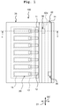
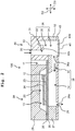
- the liquid discharge head 100 of this embodiment is formed by a pressure chamber-side portion 39 and a manifold-side portion 40 when separated in the left-right direction D2.
- the manifold-side portion 40 is disposed at the right side of the pressure chamber-side portion 39 in Figs. 1 and 2 .
- the pressure chamber-side portion 39 includes lead electrodes 12, piezoelectric elements 20 provided corresponding to nozzles 28 described below, an elastic film 26, a channel forming substrate 27, and a protective substrate 29.
- the channel forming substrate 27 is also used in the manifold-side portion 40. Details of the manifold-side portion 40 are described below.
- Each piezoelectric element 20 includes a piezoelectric body layer 23, an upper electrode film 24, and a lower electrode film 25.
- the protective substrate 29 is formed, for example, by silicon.
- the protective substrate 29 has, for example, an inverted U-shape (inverted concave shape). This provides an arrangement space 13 for arranging the piezoelectric elements 20 at the lower side of the protective substrate 29.
- the piezoelectric elements 20 are arranged in the arrangement space 13.
- the elastic film 26 is provided between the protective substrate 29 and a portion that is included in the channel forming substrate 27 and that forms the pressure chamber-side portion 39.
- the elastic film 26 is formed, for example, from silicon dioxide.
- the elastic film 26 has a thickness of 1 to 2 ⁇ m.
- the lower electrode film 25, the piezoelectric body layers 23, and the upper electrode film 24 are formed and stacked on the elastic film 26.
- the lower electrode film 25 functions as a common electrode of the piezoelectric element 20
- the upper electrode film 24 functions as individual electrode of the piezoelectric element 20.
- the lower electrode film 25 may be formed to function as the individual electrode and the upper electrode film 24 may be formed to function as the common electrode depending on the convenience of wiring or the like.
- the elastic film 26 and the lower electrode film 25 function as a vibration plate.
- the lead electrodes 12 are formed, for example, from gold. A first end of the lead electrode 12 is connected to the upper electrode film 24 of the corresponding piezoelectric element 20. A second end of the lead electrode 12 is disposed at the lower side of the space 11.
- the channel forming substrate 27 is formed, for example, from a silicon single crystal substrate.
- a nozzle plate 43 is stacked on a lower surface of the channel forming substrate 27. The nozzle plate 43 extends over the pressure chamber-side portion 39 and the manifold-side portion 40.
- a portion that is included in the channel forming substrate 27 and that forms the pressure chamber-side portion 39 is provided with liquid supply channels 37 communicating with respective individual outlet parts 36a of a downstream-side part 32 described below, pressure chambers 14, and the nozzles 28.
- the liquid supply channel 37 and the pressure chamber 14 form the individual channel 38.
- the individual outlet parts 36a of the downstream-side part 32 described below are connected to inlets of the respective liquid supply channels 37. Outlets of the liquid supply channels 37 communicate with the respective pressure chambers 14.
- the nozzles 28 are formed in the nozzle plate 43. Upstream ends of the nozzles 28 communicate with the respective pressure chambers 14, and downstream ends thereof are nozzle holes 28a.
- the manifold-side portion 40 includes an upstream-side part (upstream-side structure) 31 and the downstream-side part (downstream-side structure) 32 that form a liquid channel, and a manifold partitioning wall 42.
- the downstream-side part 32 is a portion that is included in the channel forming substrate 27 and that forms the manifold-side portion 40.
- the upstream-side part 31 is formed to have substantially a cylindrical shape by injection molding, for example.
- the downstream-side part 32 is formed to have substantially a cylindrical shape by wet etching, for example. Accordingly, the upstream-side portions 33 are formed, as space areas, in the upstream-side part 31, and the downstream-side portion 34 is formed, as a space area, in the downstream-side part 32.
- the downstream-side part 32 is joined to the upstream-side part 31.
- the upstream-side part 31 and the downstream-side part 32 are thus formed integrally.
- a lower end surface of the upstream-side part 31 is flush with a lower surface of the elastic film 26.
- An upper end surface of the downstream-side part 32 is flush with an upper surface of the channel forming substrate 27.
- the upstream-side part 31 is formed, for example, from resin.
- the upstream-side portions 33, the downstream-side portion 34, and a communication portion 35 described below form a manifold 36.
- two inlet parts 30 are provided in an upper surface of the upstream-side part 31.
- the inlet parts 30 are arranged to be shifted from each other in the front-rear direction D1 (a direction in which the individual outlet parts 36a described below are arranged). Further, the inlet parts 30 are arranged to be shifted from each other in the left-right direction D2 orthogonal to the front-rear direction D1. That is, one of the inlet parts 30 is disposed at a predefined interval in the front-rear direction D1 from the other of the inlet parts 30. Further, one of the inlet parts 30 is disposed at a predefined interval in the left-right direction D2 from the other of the inlet parts 30.
- the individual outlet parts 36a are provided in the downstream-side part 32 of the manifold-side portion 40. Specifically, the individual outlet parts 36a are provided in a side surface of the downstream-side part 32 at one side in a short-side or lateral direction (i.e., left-right direction D2) of the manifold 36. That is, the individual outlet parts 36a are arranged in the front-rear direction D1.
- the respective inlet parts 30 are provided corresponding to multiple kinds of liquids.
- the pigment as the liquid inflows into one of the inlet parts 30 and the dye as the liquid inflows into the other of the inlet parts 30 More specifically, the pigment as the liquid inflows into the inlet part 30 (inlet part 30 at the lower side in Fig. 3A ) included in the inlet parts 30 and closer to the individual outlet parts 36a.
- the dye and the pigment have, for example, the same color.
- the inlet parts 30 are arranged to overlap with the manifold 36 in plan view. That is, the manifold 36 is disposed right below (directly below) the inlet parts 30. Each of the inlet parts 30 communicates with the corresponding one of the upstream-side portions 33 of the manifold 36. That is, the upstream-side portions 33 of the manifold 36 correspond respectively to the inlet parts 30, and different channels are formed by separating one of the upstream-side portions 33 from the other of the upstream-side portions 33 by use of the manifold partitioning wall portion 42. Accordingly, in this embodiment, some regions (i.e., the two upstream-side portions 33) of the manifold 36 are defined or separated by the manifold partitioning wall portion 42.
- the manifold partitioning wall portion 42 is formed so that a center portion 42a in the left-right direction D2 protrudes downward beyond the remaining portion thereof.
- a lower surface of the center portion 42a is provided at a position higher than a joining surface between the upstream-side part 31 and the downstream-side part 32.
- the communication portion 35 through which a lower portion of one of the upstream-side portions 33 communicates with a lower portion of the other of the upstream-side portions 33, is formed in an area at the lower side of the center portion 42a of the manifold partitioning wall portion 42.
- the two upstream-side portions 33 as the different channels but also the communication portion 35 as a common channel for the pigment and the dye are formed in the upstream-side part 31 according to this embodiment.
- the communication portion 35 communicates with the downstream-side portion 34 formed by the downstream-side part 32.
- the downstream-side portion 34 communicates with the respective upstream-side portions 33 via the communication portion 35. That is, the downstream-side portion 34 is a common area for the upstream-side portions 33.
- the downstream-side portion 34 communicates with the individual outlet parts 36a.
- the individual outlet parts 36a communicate with the respective liquid supply channels 37 in the pressure chamber-side portion 39. Thus, liquid in the downstream-side portion 34 is dispersedly supplied to the respective liquid supply channels 37 via the individual outlet parts 36a.
- An opening 43a is provided at a portion that is included in the nozzle plate 43 and that is positioned at the lower side of the downstream-side part 32.
- a damper 45 is formed to cover the opening 43a of the nozzle plate 43 from below.
- the damper 45 is smaller in thickness than the nozzle plate 43.
- the damper 45 is provided at the lower side of the inlet parts 30.
- liquid from a tank (not depicted) is supplied to the manifold 36 through the inlet part 30 of the liquid discharge head 100.
- Liquid from the inlet part 30 is supplied to the individual outlet parts 36a through the manifold 36.
- an area including the manifold 36, the liquid supply channels 37, the pressure chambers 14, and the nozzles 28 is filled with the liquid.
- driving voltage is applied to the upper electrode films 24 corresponding to the respective pressure chambers 14 by the lead electrodes 12 based on a driving signal(s) from a driving IC (not depicted).
- the piezoelectric body layers 23 contract in a planar direction together with the upper electrode films 24 and the lower electrode film 25 depending on the driving signal(s).
- Pressure in the pressure chambers 14 is thus increased to discharge liquid droplets from the nozzle holes 28a of the nozzles 28.
- Fig. 4A is a cross-sectional view taken along a line IVA-IVA in Fig. 3A .
- Fig. 4B is a cross-sectional view taken along a line IVB-IVB in Fig. 3A .
- Fig. 4C is a cross-sectional view taken along a line IVC-IVC in Fig. 3A .
- each inlet part 30 has a shape widening (in diameter) from its upper portion toward its lower portion, for example, flared share (i.e., a circumferential surface defining the inlet has a shape widening in diameter from an inflow side toward an outflow side).
- a widening portion may include, for example, a portion formed into at least one of a tapered shape and an arc shape.
- the channel of the upstream-side portion 33 of the manifold 36 includes the portion formed into at least one of the tapered shape and the arc shape.
- the inlet port 30 corresponding to the upstream-side portion 33 depicted in Fig. 4A is disposed at a first side in the front-rear direction D1 (the left side in Figs. 3A and 4A ) as depicted in Fig. 3A .
- D1 front-rear direction
- the inlet port 30 corresponding to the upstream-side portion 33 in Fig. 4B is disposed at a second side in the front-rear direction D1 (the right side in Figs. 3A and 4A ) as depicted in Fig. 3A .
- the left portion extends from the upper side toward the lower side more greatly in the front-rear direction D1 than its right portion as viewed in the cross-sectional view of Fig. 4B .
- a maximum length in the front-rear direction D1 of the upstream-side portion 33 is shorter than a maximum length in the front-rear direction D1 of the downstream-side portion 34.
- a level difference (stepped portion) protruding toward the inside of the manifold 36 is prevented from being formed between the upstream-side portion 33 and the downstream-side portion 34. This prevents a situation in which liquid stays at the stepped portion.
- An openable and closable valve (two-way valve) 41 is provided for each inlet part 30.
- the openable and closable valve 41 can switch its position between an open position where the valve 41 allows liquid to flow downstream and a closed position where the flowing of liquid toward the downstream-side is blocked by the valve 41.
- the openable and closable valve 41 may be configured, for example, by any of a valve using a piezoelectric element, an electromagnetic valve, and a ball valve.
- a concept or a wording of the inlet part 30 includes a hole (space) and a part (wall) forming or defining the hole.
- a concept or a wording of the individual outlet part 36a includes a hole (space) and a part (wall) forming or defining the hole
- a concept or a wording of the manifold 36 includes a hole (space) and a part (wall) forming or defining the hole.
- the manifold 36 is formed by the upstream-side portions 33 corresponding to the respective inlet parts 30 and the downstream-side portion 34 that is common to the respective upstream-side portions 33.
- a switching mechanism such as a three-port valve is not required, a configuration for switching liquid supply can be downsized.
- a preceding liquid remaining in long channels including a supply channel, a reservoir, and individual channels is required to be drained (discharged) before a following liquid is introduced into the apparatus.
- the switching of liquid supply can be performed at a side more downstream than the conventional configuration.
- a time required for draining (discharging) the residual preceding liquid can be shortened, and following liquid can be introduced into the manifold 36 through the inlet part 30 corresponding thereto immediately after the preceding liquid is discharged.
- multiple kinds of liquids can be discharged quickly.
- the switching of liquid supply can be performed at the upstream-side portions 33 of the manifold 36, and thus the liquid channel(s) (i.e., an area(s) where liquid is required to be replaced) can be shorter than that (those) in the conventional apparatus.
- the inner space of the inlet part 30 has the shape widening (in diameter) from the upper portion toward the lower portion, liquid can inflow thereinto smoothly.
- the channel forming the upstream-side portion 33 of the manifold 36 includes the portion formed into at least one of the tapered shape and the arc shape. This allows liquid to inflow thereinto smoothly.
- the respective inlet parts 30 are arranged to overlap with the manifold 36 in plan view.
- the manifold 36 is disposed directly below the respective inlet parts 30. In this configuration, liquid from the inlet parts 30 inflows into the manifold 36 easily.
- the respective inlet parts 30 are arranged to be shifted from each other in the arrangement direction D1 (direction in which the individual outlet parts 36a are arranged). Further, the inlet parts 30 are arranged to be shifted from each other in the left-right direction D2 that is orthogonal to the front-rear direction D1. That is, one of the inlet parts 30 and the other of the inlet parts 30 are arranged at predefined intervals in the front-rear direction D1 and the left-right direction D2. In this configuration, it is possible to easily arrange supply joints for supplying liquids to the respective inlet parts 30.
- the damper 45 is formed at the lower side of the downstream-side part 32.
- the damper 45 is provided below the inlet parts 30.
- liquid introduced from each of the inlet parts 30 can be led to the liquid supply channels 37 in a state where the pressure of the liquid introduced from the inlet part 30 is absorbed by the damper 45.
- the openable and closable valves 41 are provided for the respective inlet parts 30.
- the state where liquid is allowed to flow downstream and the state where the flowing of liquid toward the downstream-side is blocked can be switched by the openable and closable valve 41, that is, by a simple configuration.
- the structure of the openable and closable valve 41 is not complicated by adopting, as the openable and closable 41, any of the valve using the piezoelectric element, the electromagnetic valve, the ball valve, and the like.
- liquids discharged from the liquid discharge head 100 include a pigment, a dye, a pre-treatment agent, and a post-treatment agent. Even in the liquid discharge head 100 from which four kinds of liquids are discharged, it is possible to discharge multiple kinds of liquids quickly as described above.
- the pigment is typically liable to stagnate in channels.
- the pigment is made to inflow into the inlet part 30 closer to the individual outlet parts 36a as descried above, shortening the channel lengths ranging from the inlet part 30 to the individual outlet parts 36a, compared to a case where the pigment inflows into the inlet part 30 farther from the individual outlet parts 36a (inlet part 30 at the upper side in Fig. 3A ). Therefore, the pigment is not likely to stagnate in channels in this embodiment.
- the communication portion 35 is provided to allow the lower portion of the upstream-side portion 33 corresponding to one of the inlet parts 30 to communicate with the lower portion of the upstream-side portion 33 corresponding to the other of the inlet parts 30.
- the communication portion 35 function as the common channel. This makes the volume of the common channel of the liquid large.
- the manifold 36 is formed by integrally joining the upstream-side part 31 that forms the upstream-side portions 33 and the downstream-side part 32 of the channel forming substrate 27 that forms the pressure chambers 14, the liquid supply channels 37, and the downstream-side portion 34.
- This configuration is simple and makes the volume of the manifold 36 large.
- the maximum length in the front-rear direction D1 of the upstream-side portion 33 is shorter than the maximum length in the front-rear direction D1 of the downstream-side portion 34.
- a level difference (stepped portion) protruding toward the inside of the manifold 36 is prevented from being formed between the upstream-side portion 33 and the downstream-side portion 34. This prevents a situation in which liquid stays at the stepped portion, making it possible to supply liquid downward smoothly.
- a liquid discharge head according to a second embodiment is described below.
- the two inlet parts 30 are provided in the liquid discharge head 100 of the first embodiment, three inlet parts (that is, two inlet parts 30 and one cleaner inlet part 30A) are provided in a liquid discharge head of the second embodiment.
- the constitutive parts or components, which are the same as or equivalent to those of the first embodiment, are designated by the same reference numerals, any explanation therefor is omitted as appropriate.
- a manifold-side portion 40A of this embodiment includes an upstream-side part 31A and a downstream-side part 32A.
- an upper portion of the upstream-side part 31A is provided with the two inlet parts 30 and a cleaner inlet part 30A.
- the inlet parts 30 are arranged to be shifted from each other in the front-rear direction D1. Further, the inlet parts 30 are arranged to be shifted from each other in the left-right direction D2.
- the cleaner inlet part 30A is positioned between one of the inlet parts 30 and the other of the inlet parts 30 in the front-rear direction D1 and the left-right direction D2.
- each of the inlet parts 30 and the cleaner inlet part 30A adjacent to each other are arranged at predefined intervals in the front-rear direction D1 and the left-right direction D2.
- the inlet parts 30 and the cleaner inlet part 30A are provided corresponding respectively to three kinds of liquids. Specifically, for example, a pigment as the liquid inflows into the inlet part 30 at a first side in the front-rear direction D1 (left side in Fig. 5A ), and a dye as the liquid inflows into the inlet part 30 at a second side in the front-rear direction D1 (right side in Fig. 5A ). Further, a cleaner as the liquid inflows into the cleaner inlet part 30A. Similar to the first embodiment, the dye and the pigment may have the same color in the second embodiment.
- the inlet parts 30 are arranged to overlap with the manifold 36 in plan view. That is, the manifold 36 is disposed directly below the inlet parts 30.
- the inlet part 30 at the first side in the front-rear direction D1 and the inlet part 30 at the second side in the front-rear direction D1 communicate with the corresponding upstream-side portions 33 of the manifold 36, respectively. Meanwhile, as depicted in Fig.
- a manifold partitioning wall portion 50 defines the upstream-side portion 33 at the left side in the left-right direction D2 communicating with the inlet part 30 at the first side in the front-rear direction D1 and the upstream-side portion 33 at the right side in the left-right direction D2 communicating with the inlet part 30 at the second side in the front-rear direction D1.
- the manifold partitioning wall portion 50 is similar in shape to the manifold partitioning wall portion 42 in the first embodiment, the manifold partitioning wall portion 50 is different from the manifold partitioning wall portion 42 in that a through hole part 51 extending in the up-down direction D3 in Fig. 6B is formed at the center in the left-right direction D2 of the manifold partitioning wall portion 50.
- An upper end of the through hole part 51 communicates with the cleaner inlet part 30A disposed at the center in the front-rear direction D1 as described above.
- liquid from the cleaner inlet part 30A disposed at the center flows through the through hole part 51 and then inflows into the communication portion 35 of the manifold 36.
- a channel forming the through hole part 51 that communicates with the cleaner inlet part 30A extends symmetrically in the front-rear direction D1 from the upper side toward the lower side in planar view so that a length in the front-rear direction D1 of a lower portion of the channel is longer than a length in the front-rear direction D1 of an upper portion of the channel.
- the shape of the upstream-side portion 33 (the shape of the upstream-side part 31) that communicates with the inlet part 30 at the first side in the front-rear direction D1 (left side in Fig.
- the shape of the upstream-side portion 33 (the shape of the upstream-side part 31) of the first embodiment (see Fig. 4A ).
- the shape of the upstream-side portion 33 (the shape of the upstream-side part 31) that communicates with the inlet part 30 at the second side in the front-rear direction D1 (right side in Fig. 5A ) is the same as the shape of the upstream-side portion 33 (the shape of the upstream-side part 31) in the first embodiment (see Fig. 4B ).
- a maximum length in the front-rear direction D1 of the through hole part 51 depicted in Fig. 6A is shorter than a maximum length in the front-rear direction D1 of the downstream-side portion 34.
- a level difference (stepped portion) protruding toward the inside of the manifold 36 is prevented from being formed between the through hole part 51 and the downstream-side portion 34. This prevents a situation in which liquid stays at the stepped portion.
- a concept or a wording of the through hole part 51 includes a hole (space) and a part (wall) forming or defining the hole.
- an increase in size of a discharge apparatus including the liquid discharge head 100 of the second embodiment is inhibited. Further, similar to the first embodiment, it is possible to discharge multiple kinds of liquids quickly and to downsize the configuration for switching the liquid supply. Furthermore, similar to the first embodiment, an amount of the residual liquid in the second embodiment is smaller than that in the conventional apparatus. It is thus possible to make an area where liquids are mixed (color mixture area) small and to reduce a drain amount (discharge amount) of residual liquid.
- the cleaner can inflow into the cleaner inlet part 30A, it is possible to quickly clean portions of the manifold 36 (in particular, the communication portion 35 and the downstream-side portion 34). Further, since the cleaner inlet part 30A is disposed between the inlet part 30 at the left side and the inlet part 30 at the right side, it is possible to supply the cleaner over the whole of the manifold 36 in the front-rear direction D1. Accordingly, it is possible to clean the communication portion 35 and the downstream-side portion 34 quickly.
- the present invention is not limited to the embodiments described above, and the present invention can be variously modified within a range without deviating from the gist or essential characteristics of the present invention.
- the modification can be made, for example, as follows.
- the manifold 36 is formed by integrally joining the upstream-side part 31 that forms the upstream-side portions 33 and the communication portion 35 and the downstream-side part 32 that forms the downstream-side portion 34.
- the present disclosure is not limited thereto.
- the manifold 36 may be formed by one component or part.
- the configuration in which the damper 45, which is a member different from the nozzle plate 43, is disposed below the inlet parts 30, is adopted.
- the damper 45 may be formed by performing, for example, half-etching on the nozzle plate 43.
- the manifold partitioning wall portion 42 is formed by one component. However, it is not limited thereto.
- the manifold partitioning wall portion 42 may be formed by joining two components that are divided at the center in the left-right direction D2.
- the intervals between the inlet parts 30 are regular intervals. However, it is not limited thereto. One or both of the intervals in the front-rear direction D1 and the left-right direction D2 may not be the regular interval(s).
- each inlet part 30 has the shape widening (in diameter) from its upper portion toward its lower portion.
- the internal space of each inlet part 30 may have, for example, a straight shape in which the upper portion and the lower portion have the same diameter.
- the communication portion 35 is formed between the upstream-side portion 33 and the downstream-side portion 34 by providing the manifold partitioning wall portion 42 so that the lower surface of the center portion of the manifold partitioning wall portion 42 is positioned at the position higher than the joining surface between the upstream-side part 31 and the downstream-side part 32.
- the two or three inlets are provided to allow multiple kinds of liquids to flow therethrough.
- inlet parts 30 and cleaner inlet part 30A are provided to allow multiple kinds of liquids to flow therethrough.
- Four or more inlets may be provided.
- the cleaner as the liquid inflows into the cleaner inlet part 30A the cleaner as the liquid inflows into the cleaner inlet part 30A.
- the present disclosure is not limited thereto.
- any other liquid such as a pre-treatment agent and a post-treatment agent may inflow into the cleaner inlet part 30A.
Landscapes
- Ink Jet (AREA)
- Particle Formation And Scattering Control In Inkjet Printers (AREA)
Applications Claiming Priority (1)
| Application Number | Priority Date | Filing Date | Title |
|---|---|---|---|
| JP2020076237A JP7452222B2 (ja) | 2020-04-22 | 2020-04-22 | 液体吐出ヘッド |
Publications (1)
| Publication Number | Publication Date |
|---|---|
| EP3900935A1 true EP3900935A1 (de) | 2021-10-27 |
Family
ID=75588098
Family Applications (1)
| Application Number | Title | Priority Date | Filing Date |
|---|---|---|---|
| EP21169283.5A Withdrawn EP3900935A1 (de) | 2020-04-22 | 2021-04-20 | Flüssigkeitsausstosskopf |
Country Status (3)
| Country | Link |
|---|---|
| US (1) | US11420439B2 (de) |
| EP (1) | EP3900935A1 (de) |
| JP (1) | JP7452222B2 (de) |
Families Citing this family (1)
| Publication number | Priority date | Publication date | Assignee | Title |
|---|---|---|---|---|
| JP2024055314A (ja) | 2022-10-07 | 2024-04-18 | キヤノン株式会社 | 液体吐出ヘッドおよび液体吐出ヘッドの検査方法 |
Citations (3)
| Publication number | Priority date | Publication date | Assignee | Title |
|---|---|---|---|---|
| US20020163562A1 (en) * | 1998-10-30 | 2002-11-07 | Sohei Tanaka | Ink-jet printing head and ink-jet printing apparatus |
| JP2008012819A (ja) | 2006-07-06 | 2008-01-24 | Toshiba Tec Corp | インクジェット記録装置及びその記録装置の洗浄方法 |
| JP2012200948A (ja) | 2011-03-24 | 2012-10-22 | Seiko Epson Corp | 液体噴射装置および液体噴射装置における供給液体切り替え方法 |
Family Cites Families (6)
| Publication number | Priority date | Publication date | Assignee | Title |
|---|---|---|---|---|
| JP2007230006A (ja) * | 2006-02-28 | 2007-09-13 | Seiko Epson Corp | 液体噴射装置、液体噴射装置の液体切替方法、液体噴射装置における噴射ヘッドの洗浄方法 |
| JP5487717B2 (ja) * | 2009-05-19 | 2014-05-07 | セイコーエプソン株式会社 | 印刷装置、および印刷装置におけるインク流路洗浄制御方法 |
| JP2011167958A (ja) * | 2010-02-19 | 2011-09-01 | Seiko Epson Corp | 液体噴射装置 |
| JP5948905B2 (ja) * | 2012-01-31 | 2016-07-06 | ブラザー工業株式会社 | 液滴吐出装置 |
| JP6492891B2 (ja) * | 2015-03-31 | 2019-04-03 | ブラザー工業株式会社 | 液体吐出装置及び液体吐出装置ユニット |
| JP7338205B2 (ja) * | 2019-04-01 | 2023-09-05 | ブラザー工業株式会社 | 液体吐出ヘッド |
-
2020
- 2020-04-22 JP JP2020076237A patent/JP7452222B2/ja active Active
-
2021
- 2021-04-20 EP EP21169283.5A patent/EP3900935A1/de not_active Withdrawn
- 2021-04-22 US US17/237,703 patent/US11420439B2/en active Active
Patent Citations (3)
| Publication number | Priority date | Publication date | Assignee | Title |
|---|---|---|---|---|
| US20020163562A1 (en) * | 1998-10-30 | 2002-11-07 | Sohei Tanaka | Ink-jet printing head and ink-jet printing apparatus |
| JP2008012819A (ja) | 2006-07-06 | 2008-01-24 | Toshiba Tec Corp | インクジェット記録装置及びその記録装置の洗浄方法 |
| JP2012200948A (ja) | 2011-03-24 | 2012-10-22 | Seiko Epson Corp | 液体噴射装置および液体噴射装置における供給液体切り替え方法 |
Also Published As
| Publication number | Publication date |
|---|---|
| CN113524910A (zh) | 2021-10-22 |
| JP7452222B2 (ja) | 2024-03-19 |
| US20210331472A1 (en) | 2021-10-28 |
| US11420439B2 (en) | 2022-08-23 |
| JP2021171971A (ja) | 2021-11-01 |
Similar Documents
| Publication | Publication Date | Title |
|---|---|---|
| KR101942142B1 (ko) | 액체 저장 유닛, 이를 사용한 액체 토출 장치 및 액체 저장 유닛으로부터 기포를 제거하는 방법 | |
| US9539820B2 (en) | Tank unit and liquid ejecting system having tank unit | |
| KR101484827B1 (ko) | 액체 수용 용기, 및, 액체 분사 시스템 | |
| JP7230484B2 (ja) | 液体吐出ヘッド | |
| JP2018012291A (ja) | ヘッドモジュール、液体吐出装置、及び、ケース | |
| US20170266973A1 (en) | Printhead assembly | |
| US11420439B2 (en) | Liquid discharge head | |
| EP2043869A2 (de) | Druckerpatronenelement | |
| US11065870B2 (en) | Liquid ejection head having plurality of sets of rows of pressure chambers, and capable of avoiding mixture of different kinds of liquid | |
| EP3560718A1 (de) | Tintenstrahlkopf und bilderzeugungsvorrichtung | |
| CN113524910B (zh) | 液体排出头 | |
| US20200079088A1 (en) | Liquid discharge head | |
| JP7298147B2 (ja) | 液体吐出ヘッド | |
| CN105691003A (zh) | 密封部件、具备该密封部件的液体排出头、以及液体排出装置 | |
| JP4985639B2 (ja) | 液体吐出装置 | |
| US7806511B2 (en) | Liquid ejection apparatus | |
| KR100503082B1 (ko) | 잉크젯 프린터용 잉크 카트리지 | |
| US10981384B2 (en) | Liquid discharge head | |
| JP4501887B2 (ja) | インクジェットヘッド | |
| JP2019038125A (ja) | 液体吐出装置およびフィルターユニット | |
| CN106427221A (zh) | 液体供应单元 | |
| JP4379465B2 (ja) | 液体噴射装置 | |
| JP4552476B2 (ja) | インクジェットプリンタ | |
| CN110949004B (zh) | 流道部件、头单元以及头单元组 | |
| JP4470533B2 (ja) | インクジェットプリンタ |
Legal Events
| Date | Code | Title | Description |
|---|---|---|---|
| PUAI | Public reference made under article 153(3) epc to a published international application that has entered the european phase |
Free format text: ORIGINAL CODE: 0009012 |
|
| STAA | Information on the status of an ep patent application or granted ep patent |
Free format text: STATUS: THE APPLICATION HAS BEEN PUBLISHED |
|
| AK | Designated contracting states |
Kind code of ref document: A1 Designated state(s): AL AT BE BG CH CY CZ DE DK EE ES FI FR GB GR HR HU IE IS IT LI LT LU LV MC MK MT NL NO PL PT RO RS SE SI SK SM TR |
|
| B565 | Issuance of search results under rule 164(2) epc |
Effective date: 20210923 |
|
| STAA | Information on the status of an ep patent application or granted ep patent |
Free format text: STATUS: REQUEST FOR EXAMINATION WAS MADE |
|
| 17P | Request for examination filed |
Effective date: 20220413 |
|
| RBV | Designated contracting states (corrected) |
Designated state(s): AL AT BE BG CH CY CZ DE DK EE ES FI FR GB GR HR HU IE IS IT LI LT LU LV MC MK MT NL NO PL PT RO RS SE SI SK SM TR |
|
| P01 | Opt-out of the competence of the unified patent court (upc) registered |
Effective date: 20230529 |
|
| STAA | Information on the status of an ep patent application or granted ep patent |
Free format text: STATUS: EXAMINATION IS IN PROGRESS |
|
| 17Q | First examination report despatched |
Effective date: 20231009 |
|
| GRAP | Despatch of communication of intention to grant a patent |
Free format text: ORIGINAL CODE: EPIDOSNIGR1 |
|
| STAA | Information on the status of an ep patent application or granted ep patent |
Free format text: STATUS: GRANT OF PATENT IS INTENDED |
|
| INTG | Intention to grant announced |
Effective date: 20250129 |
|
| STAA | Information on the status of an ep patent application or granted ep patent |
Free format text: STATUS: THE APPLICATION IS DEEMED TO BE WITHDRAWN |
|
| 18D | Application deemed to be withdrawn |
Effective date: 20250531 |