EP3900644B1 - Nahtlose klammer für vaskuläre anastomose - Google Patents
Nahtlose klammer für vaskuläre anastomose Download PDFInfo
- Publication number
- EP3900644B1 EP3900644B1 EP20857786.6A EP20857786A EP3900644B1 EP 3900644 B1 EP3900644 B1 EP 3900644B1 EP 20857786 A EP20857786 A EP 20857786A EP 3900644 B1 EP3900644 B1 EP 3900644B1
- Authority
- EP
- European Patent Office
- Prior art keywords
- rotating shaft
- end part
- suture
- vascular anastomosis
- binding belt
- Prior art date
- Legal status (The legal status is an assumption and is not a legal conclusion. Google has not performed a legal analysis and makes no representation as to the accuracy of the status listed.)
- Active
Links
Images


Classifications
-
- A—HUMAN NECESSITIES
- A61—MEDICAL OR VETERINARY SCIENCE; HYGIENE
- A61B—DIAGNOSIS; SURGERY; IDENTIFICATION
- A61B17/00—Surgical instruments, devices or methods
- A61B17/11—Surgical instruments, devices or methods for performing anastomosis; Buttons for anastomosis
-
- A—HUMAN NECESSITIES
- A61—MEDICAL OR VETERINARY SCIENCE; HYGIENE
- A61B—DIAGNOSIS; SURGERY; IDENTIFICATION
- A61B17/00—Surgical instruments, devices or methods
- A61B17/12—Surgical instruments, devices or methods for ligaturing or otherwise compressing tubular parts of the body, e.g. blood vessels or umbilical cord
- A61B17/122—Clamps or clips, e.g. for the umbilical cord
-
- A—HUMAN NECESSITIES
- A61—MEDICAL OR VETERINARY SCIENCE; HYGIENE
- A61F—FILTERS IMPLANTABLE INTO BLOOD VESSELS; PROSTHESES; DEVICES PROVIDING PATENCY TO, OR PREVENTING COLLAPSING OF, TUBULAR STRUCTURES OF THE BODY, e.g. STENTS; ORTHOPAEDIC, NURSING OR CONTRACEPTIVE DEVICES; FOMENTATION; TREATMENT OR PROTECTION OF EYES OR EARS; BANDAGES, DRESSINGS OR ABSORBENT PADS; FIRST-AID KITS
- A61F2/00—Filters implantable into blood vessels; Prostheses, i.e. artificial substitutes or replacements for parts of the body; Appliances for connecting them with the body; Devices providing patency to, or preventing collapsing of, tubular structures of the body, e.g. stents
-
- A—HUMAN NECESSITIES
- A61—MEDICAL OR VETERINARY SCIENCE; HYGIENE
- A61B—DIAGNOSIS; SURGERY; IDENTIFICATION
- A61B17/00—Surgical instruments, devices or methods
- A61B2017/00477—Coupling
-
- A—HUMAN NECESSITIES
- A61—MEDICAL OR VETERINARY SCIENCE; HYGIENE
- A61B—DIAGNOSIS; SURGERY; IDENTIFICATION
- A61B17/00—Surgical instruments, devices or methods
- A61B17/11—Surgical instruments, devices or methods for performing anastomosis; Buttons for anastomosis
- A61B2017/1107—Surgical instruments, devices or methods for performing anastomosis; Buttons for anastomosis for blood vessels
-
- A—HUMAN NECESSITIES
- A61—MEDICAL OR VETERINARY SCIENCE; HYGIENE
- A61B—DIAGNOSIS; SURGERY; IDENTIFICATION
- A61B17/00—Surgical instruments, devices or methods
- A61B17/11—Surgical instruments, devices or methods for performing anastomosis; Buttons for anastomosis
- A61B2017/1132—End-to-end connections
-
- A—HUMAN NECESSITIES
- A61—MEDICAL OR VETERINARY SCIENCE; HYGIENE
- A61B—DIAGNOSIS; SURGERY; IDENTIFICATION
- A61B90/00—Instruments, implements or accessories specially adapted for surgery or diagnosis and not covered by any of the groups A61B1/00 - A61B50/00, e.g. for luxation treatment or for protecting wound edges
- A61B90/06—Measuring instruments not otherwise provided for
- A61B2090/061—Measuring instruments not otherwise provided for for measuring dimensions, e.g. length
-
- A—HUMAN NECESSITIES
- A61—MEDICAL OR VETERINARY SCIENCE; HYGIENE
- A61F—FILTERS IMPLANTABLE INTO BLOOD VESSELS; PROSTHESES; DEVICES PROVIDING PATENCY TO, OR PREVENTING COLLAPSING OF, TUBULAR STRUCTURES OF THE BODY, e.g. STENTS; ORTHOPAEDIC, NURSING OR CONTRACEPTIVE DEVICES; FOMENTATION; TREATMENT OR PROTECTION OF EYES OR EARS; BANDAGES, DRESSINGS OR ABSORBENT PADS; FIRST-AID KITS
- A61F2220/00—Fixations or connections for prostheses classified in groups A61F2/00 - A61F2/26 or A61F2/82 or A61F9/00 or A61F11/00 or subgroups thereof
- A61F2220/0008—Fixation appliances for connecting prostheses to the body
Definitions
- the present disclosure relates to the technical field of vascular anastomosis, in particular, to a suture-free clasp (i.e., fastening ring) for vascular anastomosis.
- a suture-free clasp i.e., fastening ring
- aortic diseases such as aortic aneurysm, particularly aortic dissection aneurysm, have the characteristics of acute onset, rapid disease progression, complex disease condition, and extremely high mortality.
- Most patients with aortic aneurysm including aortic dissection aneurysm need surgical treatment, and an artificial large blood vessel is used to replace a diseased artery during treatment.
- DHCA Deep Hypothermia Circulatory Arrest
- cardiovascular surgeons start to perform aortic anastomosis using a sutureless method.
- This sutureless method is a sutureless intraluminal graft (SIG for short), in which positions of the patient's autologous blood vessel that needs to be anastomosed with two ends of the artificial blood vessel are two broken ends of the patient's autologous blood vessel, the artificial blood vessel with either end provided with a fixing ring is placed inside the two broken ends of the patient's autologous blood vessel, respectively, and then tied at parts corresponding to the fixing rings outside the autologous blood vessel by a tying belt, so as to complete the fixation and anastomosis.
- SIG sutureless intraluminal graft
- doctors start to knot and fix with a silk belt having a certain width.
- the doctor's visual field and operation direction should be perpendicular to an axis of the patient's autologous blood vessel so that the winding distance of the silk thread or silk belt is the shortest, thus, the shedding time of the silk thread or silk belt is prolonged as much as possible.
- the aorta has an aortic arch inclined backward after exiting from the heart, which makes the visual field and operating space of the doctor for aorta operation quite limited, therefore, it is quite difficult to obtain the most advantageous position for knotting during the operation, particularly when ligation of broken end of the aortic arch is involved.
- the silk belt will be tightly attached to the patient's autologous blood vessel, which makes it quite difficult for the doctor to disengage or readjust.
- CN208259728U discloses a blood vessel coincide with auto-lock area and uses its artificial blood vessel subassembly relates to medical instrument technical field to solve and operate inconvenient, difficult adjustment when the lantern ring of fixing artificial blood vessel is knotd to current silk thread (or silk ribbon), and the technical problem of locking effect unstability.
- the blood vessel coincide and to use the auto -lock area include: the casing, pivot, pawl, elastically returning spare, soft area, the casing is equipped with and is used for the axis body be connected with softarea for wear to establish the mating holes of pivot, be used for respectively with first, the second hole post of pawl and elastically returning spare complex, the pivot is equipped with along the axial groove that the axial distributes, and the one end of pivot is equipped with and is equipped with the operating portion along the circumferential teeth of circumference distribution, the one end that other end inclusive AND circumferential teeth is the same, the one end in soft area is connected with the axis body of casing, the other end is passed by the axial groove to driving the pivot through the operating portion and rotating, in order accomplishing tightening up of soft area, and the locking of countershaft is accomplished to the pawl under the drive of elastically returning spare.
- CN205831862U discloses a card formula bales catch rubber tourniquet is inhaled to field operations magnetism, inhale formula buckle and automatic buckle including the rubber tape body, magnetism, the one side that nearly skin was shown consideration for to the rubber tape designs into smooth curved surface, and the one side that deviates from skin designs into cockscomb structure antiskid line, magnetism is inhaled the formula buckle and is included first component and second component two parts, and automatic positioning actuation function is realized to the permanent magnet that these two a pair of heterocharge of component accessible inhale mutually, through blocking mechanism and the dual promotion of rotation type kayser locking intensity, automatic buckle includes the one-way anti-slip buckle of cockscomb structure, release button and spring, and the one-way anti-slip buckle of cockscomb structure sets up and inhales the inside rubber tape body below of the first component of formula buckle in magnetism, and release button locates magnetism and inhales the first component of formula buckle below plane department, and the spring rigid coupling
- Objectives of the present disclosure include, for example, providing a suture-free clasp for vascular anastomosis, so as to reduce the influence of human factors of doctors on the knotting position and knotting strength during vascular anastomosis, further solve the technical problems of difficult knotting operation, easy slippage of the knot to cause blood leakage and thereby form pseudoaneurysm, and difficult readjustment after the knotting is completed, existing in the prior art.
- An embodiment of the present disclosure provides a suture-free clasp for vascular anastomosis, including a first end part, a second end part, a rotating shaft, a binding belt, and a rotation-stopping structure,
- the rotation-stopping structure comprises a ratchet and a pawl, wherein the ratchet is provided on a circumferential surface of the rotating shaft; one end of the pawl is connected to the first end part, and the pawl is configured to always have a moving tendency to slide towards a position between roots of two adjacent teeth of the ratchet.
- one end of the pawl is connected to the first end part in a detachable manner.
- the first end part comprises a first end part body and a limiting portion provided on the first end part body.
- the limiting portion and the first end part body are integrally formed, as an integral structure.
- the limiting portion is a structure fixed on the first end part body.
- the limiting portion has an accommodating groove
- a fitting hole is provided on the first end part body in a position corresponding to the accommodating groove of the limiting portion.
- a fitting portion is connected to one end of the pawl, and the fitting portion is fitted into the fitting hole of the first end part body, and an end portion of an end of the pawl connected to the fitting portion is clamped in the accommodating groove of the limiting portion.
- the pawl is made of an elastic material.
- the elastic material is a metal material or a polymer material.
- the rotation-stopping structure comprises a ratchet and an end protective cover
- the fixing holes and the pins are respectively four or more.
- a long hole is provided in the middle of the rotating shaft, and the binding belt is fixed on the rotating shaft in a manner that one end of the binding belt is threaded through the long hole and then is stitched with a remaining part of the binding belt.
- a long hole is provided in the middle of the rotating shaft, and the binding belt is fixed on the rotating shaft in a manner that one end of the binding belt is threaded through the long hole and then is joined with a remaining part of the binding belt.
- the binding belt is fixed on the rotating shaft in a manner that one end of the binding belt is threaded through the long hole and then is glued, welded, heat-sealed or stitched with a remaining part of the binding belt.
- the second end part comprises a rod portion and end flanges respectively provided at both ends of the rod portion; the first end part is provided with a snap-fit groove and arc-shaped fixing portions; the snap-fit groove is configured to be capable of accommodating the rod portion; and the arc-shaped fixing portion is formed at either end of the snap-fit groove in a length direction, and is configured to be capable of being clamped with the end flange.
- the first end part is provided with a rotating shaft mounting groove
- a mounting hole is provided on an end surface of either end of the rotating shaft mounting groove, one end of the rotating shaft is inserted into one of the mounting holes, and the other end of the rotating shaft is inserted into the other mounting hole.
- the rotating shaft is made of a polymer injection molding material.
- a side of the first end part attached to an artificial blood vessel is of an arc shape.
- a marker is provided on at least one of a middle portion of the binding belt, the rotating shaft, and the second end part.
- the marker is made of a metal.
- an operating portion is provided at an end portion of the rotating shaft, and the operating portion is configured to be capable of cooperating with a surgical instrument so as to enable the rotating shaft to rotate.
- the operating portion is a polygonal operation hole provided in the end portion of the rotating shaft.
- the operating portion is a polygonal protrusion provided on the end portion of the rotating shaft.
- scales are set on an outer peripheral surface of the binding belt.
- the binding belt is made of a flexible material.
- the suture-free clasp for vascular anastomosis provided in the embodiments of the present disclosure can achieve the following beneficial effects: the embodiments of the present disclosure provide a suture-free clasp for vascular anastomosis, including a first end part, a second end part, a rotating shaft, a binding belt, and a rotation-stopping structure; the rotating shaft is rotationally installed on the first end part; one end of the binding belt is fixed on the rotating shaft, the other end of the binding belt is fixed on the second end part; the second end part is configured to be capable of being snap-fitted with the first end part; and the rotation-stopping structure is provided between the first end part and the rotating shaft, and the rotation-stopping structure is configured to be capable of locking the rotating shaft to the first end part.
- end portions of the artificial blood vessel are disposed between broken ends of the patient's autologous blood vessel and the fixing rings, then the suture-free clasp for vascular anastomosis is snap-fitted outside the broken ends of the patient's autologous blood vessel, wherein a snap-fitting process is as follows: first, the second end part and the first end part are snap-fitted to each other; then, the rotating shaft is rotated, so that the binding belt is tightened until the broken ends of the patient's autologous blood vessel are attached to the artificial blood vessel, and the rotation-stopping structure locks the rotating shaft to the first end part, thus completing a tightening and fixing process; when readjustment is needed, the suture-free clasp for vascular anastomosis may be loosened just by releasing the rotation-stopping structure, for readjusting the tightness.
- the vascular anastomosis operation is performed in a manner of rotating the rotating shaft after snap-fitting the second end part and the first end part to each other so as to tighten the binding belt, in place of a manner of completely relying on the doctor to manually wind a silk thread or a silk belt, followed by binding in the prior art.
- the binding belt has a certain width and a certain frictional force, a larger pressure is applied on a larger area, which can avoid the cutting effect brought by the silk thread, and prevent local necrosis of the blood vessel.
- the final tightening strength of the binding belt of the doctor may be maintained within a range of stable force, further avoiding slippage and bleeding caused by a too low knotting force, and blood vessel necrosis caused by a too large force; the rotation-stopping structure may make the operation in the surgery more convenient, and long-term implantation safer.
- the binding belt is provided with scales and a developing ring, then the size and position of the binding belt may be observed in and after the operation, aiding to judge whether displacement exists.
- the operations are simpler and more convenient, and when the locking state of the suture-free clasp needs to be readjusted, the clasp may be loosened just by releasing the rotation-stopping structure, so as to readjust the tightness and snap-fit position thereof, or release the snap-fit between the second end part and the first end part when the binding belt is in a loose state.
- the embodiments of the present disclosure at least reduce the influence of the doctor's human factors on the knotting position and knotting strength in the vascular anastomosis, and further solve the technical problems of difficult knotting operation, unstable knotting effect, and difficult readjustment after the knotting is completed, existing in the prior art, thus achieving convenient operation and controllable strength, facilitating adjustment and observation in and after the operation, then risks such as post-operation blood vessel necrosis and clasp slippage may be effectively reduced.
- orientation or positional relationships indicated by terms such as “center”, “inner”, and “outer”, are based on orientation or positional relationships as shown in the drawings, or orientation or positional relationships of a product of the present disclosure when being conventionally placed in use, merely for facilitating describing the present disclosure and simplifying the description, rather than indicating or suggesting that related devices or elements have to be in the specific orientation or configured and operated in a specific orientation, therefore, they should not be construed as limitation to the present disclosure.
- terms such as “first” and “second” are merely used for distinctive description, but should not be construed as indicating or implying importance in the relativity.
- connection may be fixed connection, detachable connection, or integrated connection; it may be mechanical connection or electrical connection; it may be direct joining or indirect joining through an intermediary, and it also may be inner communication between two elements.
- connection may be fixed connection, detachable connection, or integrated connection; it may be mechanical connection or electrical connection; it may be direct joining or indirect joining through an intermediary, and it also may be inner communication between two elements.
- the suture-free clasp for vascular anastomosis includes a first end part 1, a second end part 2, a rotating shaft 3, a binding belt 4, and a rotation-stopping structure 5;
- the rotating shaft 3 is rotationally installed on the first end part 1; one end of the binding belt 4 is fixed on the rotating shaft 3, the other end of the binding belt 4 is fixed on the second end part 2;
- the second end part 2 is configured to be capable of being snap-fitted with the first end part 1;
- the rotation-stopping structure 5 is provided between the first end part 1 and the rotating shaft 3, and the rotation-stopping structure 5 is configured to be capable of locking the rotating shaft 3 to the first end part 1.
- positions of a patient's autologous blood vessel that need to be anastomosed with two ends of an artificial blood vessel are taken as two broken ends of the patient's autologous blood vessel, a fixing ring is placed inside either broken end of the patient's autologous blood vessel, the artificial blood vessel is placed in a position to be anastomosed, and either end of the artificial blood vessel is inserted between an inner side of either end of the patient's autologous blood vessel and the fixing ring, respectively, then, the suture-free clasp for vascular anastomosis is snap-fitted outside the two broken ends of the patient's autologous blood vessel, wherein a snap-fitting process is as follows.
- the second end part 2 and the first end part 1 are snap-fitted to each other; then, the rotating shaft 3 is rotated, so that the binding belt 4 is tightened until the artificial blood vessel is fixed to the two broken ends of the patient's autologous blood vessel, and the rotation-stopping structure 5 locks the rotating shaft 3 to the first end part 1, thus completing a knotting process; when it is necessary to readjust the knotting condition, the suture-free clasp for vascular anastomosis may be taken out just by releasing the snap-fit between the second end part 2 and the first end part 1, so as to knot again; alternatively, the locking state of the rotation-stopping structure 5 to the rotating shaft 3 is released, so that the binding belt 4 can be loosened or tightened again, so as to adjust the knotting strength and to knot again.
- the vascular anastomosis operation is performed in a manner of rotating the rotating shaft 3 after snap-fitting the second end part 2 and the first end part 1 to each other so as to tighten the binding belt 4, in place of a manner of completely relying on the doctor to manually wind a silk thread or a silk belt, followed by binding in the prior art.
- the manner of rotating the rotating shaft 3 to tighten the binding belt 4 can maintain the doctor's knotting strength within a certain range of stable force, further avoiding occurrence of the situation in which the knotting force is too low to cause slippage of the knot or the knotting force is too large to cause a cutting effect on the patient's autologous blood vessel and other situations; moreover, the operation thereof is simpler and more convenient compared with the prior art, and when it is necessary to readjust the knocking condition, the suture-free clasp for vascular anastomosis may be taken out just by releasing the snap-fit between the second end part 2 and the first end part 1 so as to knot again, alternatively, the binding belt 4 can be loosened or tightened again just by releasing the locking state of the rotation-stop
- the present embodiment at least has the above beneficial effects of reducing the influence of human factors of doctors on the knotting position and knotting strength in the vascular anastomosis, further solving the technical problems of difficult knotting operation, easy slippage of the knot to cause blood leakage and thereby form pseudoaneurysm, and difficult readjustment after the knotting is completed, existing in the prior art.
- the rotation-stopping structure 5 is of varied structures, for example, the rotation-stopping structure includes an opening provided on the first end part 1 and the rotating shaft 3, respectively, and a fixing pin capable of passing through the first end part 1 and the rotating shaft 3 in sequence, and the first end part 1 and the rotating shaft 3 are fixed by the fixing pin.
- the rotation-stopping structure includes an opening provided on the first end part 1 and the rotating shaft 3, respectively, and a fixing pin capable of passing through the first end part 1 and the rotating shaft 3 in sequence, and the first end part 1 and the rotating shaft 3 are fixed by the fixing pin.
- the above rotation-stopping structure 5 includes a ratchet 51 and a pawl 52; the ratchet 51 is formed on a circumferential surface of the rotating shaft 3; one end of the pawl 52 is connected to the first end part 1, and the pawl 52 is configured to always have a moving tendency to slide towards a position between roots of two adjacent teeth of the ratchet 51, so that in the whole knotting process, the pawl 52 may be configured to cooperate with the ratchet 51 at any time so as to lock or unlock the rotating shaft 3, which facilitates pausing or restarting the knotting process at any time when needed, improves the operability of the knotting process, and reduces the operation difficulty.
- the design of the pawl 52 may provide sufficient knotting strength, thus effectively preventing the rotating shaft 3 from rotating reversely, and the pawl 52 is connected to the first end part 1 in a variety of structure forms, for example, without limitation, one end of the pawl 52 being fixedly connected to the first end part 1.
- one end of the pawl 52 is detachably connected to the first end part 1, specifically, as shown in FIG.
- the first end part 1 includes a first end part body and a limiting portion 7 provided on the first end part body
- the limiting portion 7 and the first end part body may be integrally formed, as an integral structure, or also may be a structure fixed on the first end part body
- the limiting portion 7 has an accommodating groove
- a fitting hole is provided on the first end part body in a position corresponding to the accommodating groove of the limiting portion 7
- a fitting portion is connected to one end of the pawl 52, and the fitting portion is fitted into the fitting hole of the first end part body, and an end portion of an end of the pawl 52 connected to the fitting portion is clamped in the accommodating groove of the limiting portion 7.
- a specific connection manner in which one end of the pawl 52 is detachably connected to the first end part 1 may also be other detachable connection forms, for example, the limiting portion 7 described above is not provided, the fitting hole is only provided on the first end part 1, one end of the pawl 52 is connected with the fitting portion, the fitting portion is fitted into the fitting hole in the first end part 1, and the fitting portion is in interference fit with a hole wall of the fitting hole.
- one end of the pawl 52 is connected to the first end part 1 in a detachable manner, thus, when the knotting condition needs to be readjusted, in addition to taking out the suture-free clasp for vascular anastomosis by releasing the snap-fit between the second end part 2 and the first end part 1 so as to knot again, the binding belt 4 may also be released by removing the pawl 52, then the binding belt 4 is retightened after the pawl 52 is reinstalled, so as to realize the function of adjusting the knotting strength.
- the pawl 52 is made of an elastic material, thus, when the rotating shaft 3 is rotated forward, the pawl 52 may be matched with the rotation of the ratchet 51 by the elasticity of the pawl, so that in the process of rotating the rotating shaft 3 to tighten the binding belt 4, the forward rotation of the rotating shaft 3 can be simultaneously realized and the reverse rotation thereof can be prevented without removing the pawl 52, thus, the structure thereof is simple, and there are the beneficial effects of simplifying the parts, and avoiding the functional failure of the suture-free clasp for vascular anastomosis in the case of more parts, wherein the elastic material may be of a metal material or other materials having certain elasticity, which is not further limited herein.
- the rotation-stopping structure 5 includes the ratchet 51 and an end protective cover 53; the ratchet 51 is formed on the circumferential surface of the rotating shaft 3; the first end part 1 is provided with fixing holes 11 in positions between adjacent teeth of the ratchet 51; the end protective cover 53 includes a cover body 531 and pins 532 connected to the cover body 531; the fixing holes 11 and the pins 532 are respectively at least two, preferably, four or more; at least two pins 532 are correspondingly inserted into the fixing holes 11, thus the rotating shaft 3 may be further positioned and protected by the end protective cover 53, thereby avoiding the rotation of the rotating shaft 3 relative to the first end part 1, so as to ensure that the binding belt 4 has a good binding effect on the artificial blood vessel.
- the protective cover 53 can prevent the rotating shaft 3 from rotating reversely and also can prevent the rotating shaft from rotating forward, so as to be suitable for being provided in a preset position after the knotting process is completed, to further position the rotating shaft 3, moreover, the protective cover 53 can cover the outside of the ratchet 51, so that an operator cannot directly contact the ratchet 51, thereby avoiding misoperation on the ratchet.
- a long hole 31 is provided in the middle of the rotating shaft 3, and the binding belt 4 is fixed on the rotating shaft 3 in a manner that one end of the binding belt is threaded through the long hole 31 and then is joined with a remaining part of the binding belt 4, wherein a joining manner is, for example, but not limited to, gluing, welding, heat sealing or stitching.
- a joining manner is, for example, but not limited to, gluing, welding, heat sealing or stitching.
- the binding belt 4 may also be directly glued on the rotating shaft 3, however, obviously, in contrast, by fixing one end of the binding belt 4 on the rotating shaft 3 according to the structure in FIG.
- the fixing structure thereof is more stable, which is beneficial to avoiding slippage of the binding belt 4 from the rotating shaft 3, and meanwhile avoiding slipping of the binding belt 4 in the rotating process of the rotating shaft 3, so as to improve the success rate of operation and the durability of operation effect.
- the second end part 2 includes a rod portion 21 and end flanges 22 respectively formed at both ends of the rod portion 21, and the end flanges 22 may be an integral structure integrally formed with the rod portion 21, or may be a structure fixed on the rod portion 21;
- the first end part 1 is provided with a snap-fit groove 12 and an arc-shaped fixing portion 13;
- the snap-fit groove 12 is configured to be capable of accommodating the rod portion 21;
- the arc-shaped fixing portion 13 is formed at either end of the snap-fit groove 12 in a length direction, and is configured to be capable of being clamped with the end flange 22.
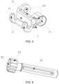
- the rotating shaft 3 is rotationally installed on the first end part 1 in a plurality of mounting manners, for example, referring to FIG. 1 and FIG. 3 , in an optional embodiment of the present example, the first end part 1 is provided with a rotating shaft mounting groove 14, a mounting hole 141 is provided on an end surface of either end of the rotating shaft mounting groove 14, one end of the rotating shaft 3 is inserted into one of the mounting holes 141, and the other end of the rotating shaft 3 is inserted into the other mounting hole 141, so that the rotating shaft 3 is rotationally mounted on the first end part 1. Further, referring to FIG.
- the rotating shaft 3 made of a polymer injection molding material, has certain elasticity, so that under the working condition that the rotating shaft 3 is assembled in the two mounting holes 141, a part of the rotating shaft 3 located between the two mounting holes 141 is an assembling part of the rotating shaft 3, and a cross-sectional area of the assembling part of the rotating shaft 3 is slightly larger than the aperture of the two mounting holes 141, thus, in the assembling process, the above assembling part of the rotating shaft 3 may be extruded through the two mounting holes 141 by means of an elastic force of the rotating shaft, and after passing, the assembling part of the rotating shaft 3 is just limited between the two mounting holes 141, thus, the rotating shaft 3 can be avoided from sliding out of the mounting holes 141, further ensuring that the rotating shaft 3 is stably connected in the two mounting holes 141.
- a side of the first end part 1 attached to the artificial blood vessel is in an arc shape.
- an operating portion 32 is provided at an end portion of the rotating shaft 3, and the operating portion 32 is configured to be capable of cooperating with a surgical instrument so as to rotate the rotating shaft 3.
- a polygonal operation hole is provided in the end portion of the rotating shaft 3 as the operating portion 32, thus, when the rotating shaft 3 is rotated, a dedicated surgical wrench can be extended into the operation hole to rotate the rotating shaft 3, which has the beneficial effects of a simple structure, a convenient operation, and a stable and reliable rotation process.
- the operating portion 32 further may be formed in other structural forms, for example, the above operating portion 32 is a polygonal protrusion formed in the end portion of the rotating shaft 3, and the rotating shaft 3 is rotated by a dedicated surgical wrench sheathed outside the polygonal protrusion.
- a rotation manner of rotating the rotating shaft 3 with the surgical instrument is provided.
- the present disclosure is not limited thereto, and it is also feasible that the above operating portion 32 is not provided, while the surgical operation is performed using a surgical instrument capable of directly clamping the end portion of the rotating shaft 3 and driving the rotating shaft 3 to rotate.
- the process of rotating the rotating shaft 3 with the surgical instrument is more convenient and more reliable by providing the dedicated operating portion 32 above, which is beneficial to shorten the surgical time and ensure stable proceeding of the rotation process, accordingly, in various optional manners of rotating the rotating shaft 3 with the surgical instrument, preferably, the structure in the above optional embodiment is used, that is, providing the above operating portion 32.
- a marker 6 is provided on at least one of a middle portion of the binding belt 4, the rotating shaft 3, and the second end part 2.
- FIG. 2 it shows that the marker 6 is provided on the middle portion of the binding belt 4.
- the above marker 6 is generally made of a metal, for example, but not limited to, noble metal materials such as gold wire or platinum iridium alloy wire, for developing and observing the position of the suture-free clasp for vascular anastomosis through X-ray irradiation in follow-up visit later, and confirming whether the suture-free clasp for vascular anastomosis is displaced or deformed, etc.
- the marker 6 is provided on at least one of the middle portion of the binding belt 4, the rotating shaft 3, and the second end part 2, for example, the marker 6 is heat-sealed or injection-molded on a corresponding structural member, as long as it can be connected to a corresponding part.
- scales are set on an outer peripheral surface of the binding belt 4 after the binding belt is snap-fitted, wherein the scales may be in units such as centimeters, millimeters, and inches, so that when the second end part 2 is snap-fitted to the first end part 1, the medical personnel can clearly and visually know dimension information such as diameter and circumference of a closed loop formed by the binding belt 4, thus, it is convenient to adjust the knotting position and the knotting strength in practical operations according to the dimension of the blood vessel.
- the binding belt 4 is made of a flexible material, and has a certain frictional force with the vascular wall, which can avoid slippage of the knot to cause blood leakage and thereby form pseudoaneurysm.
- the present disclosure provides a suture-free clasp for vascular anastomosis, which can reduce the influence of human factors of doctors on the knotting position and knotting strength in the vascular anastomosis, further solve the technical problems of difficult knotting operation, easy slippage of the knot to cause blood leakage and thereby form pseudoaneurysm, and difficult readjustment after the knotting is completed, existing in the prior art.
Landscapes
- Health & Medical Sciences (AREA)
- Life Sciences & Earth Sciences (AREA)
- Surgery (AREA)
- Veterinary Medicine (AREA)
- General Health & Medical Sciences (AREA)
- Biomedical Technology (AREA)
- Heart & Thoracic Surgery (AREA)
- Engineering & Computer Science (AREA)
- Public Health (AREA)
- Animal Behavior & Ethology (AREA)
- Medical Informatics (AREA)
- Molecular Biology (AREA)
- Nuclear Medicine, Radiotherapy & Molecular Imaging (AREA)
- Vascular Medicine (AREA)
- Reproductive Health (AREA)
- Cardiology (AREA)
- Oral & Maxillofacial Surgery (AREA)
- Transplantation (AREA)
- Surgical Instruments (AREA)
Claims (15)
- Nahtfreie Spange für die Gefäßanastomose, umfassend einen ersten Endteil (1), einen zweiten Endteil (2), eine Drehwelle (3), einen Binderiemen (4) und eine Drehstoppstruktur (5), wobeidie Drehwelle (3) an dem ersten Endteil (1) drehinstalliert ist, ein Ende des Binderiemens (4) an der Drehwelle (3) befestigt ist und das andere Ende (2) an dem zweiten Endteil (2) befestigt ist, und der zweite Endteil (2) so ausgestaltet ist, dass er in den ersten Teil (1) eingeschnappt werden kann, unddie Drehstoppstruktur (5) zwischen dem ersten Endteil (1) und der Drehwelle (3) vorgesehen ist und die Drehstoppstruktur (5) so ausgestaltet ist, dass sie die Drehwelle (3) mit dem ersten Teil (1) verriegeln kann.
- Nahtfreie Spange für die Gefäßanastomose nach Anspruch 1, wobei die Drehstoppstruktur (5) eine Ratsche (51) und eine Klinke (52) umfasst,
wobei die Ratsche (51) an einer Umfangsseite der Drehwelle (3) vorgesehen ist, ein Ende der Klinke (52) mit dem ersten Endteil (1) verbunden ist und die Klinke (52) so ausgestaltet ist, dass sie stets eine Tendenz hat, sich zu bewegen und zu einer Position zwischen Wurzeln zweier benachbarter Zähne der Ratsche (51) zu gleiten. - Nahtfreie Spange für die Gefäßanastomose nach Anspruch 2, wobei ein Ende der Klinke (52) mit dem ersten Endteil (1) auf eine lösbare Weise verbunden ist.
- Nahtfreie Spange für die Gefäßanastomose nach einem der Ansprüche 1 - 3, wobei der erste Endteil (1) einen ersten Endteilkörper und einen an dem ersten Endteilkörper vorgesehenen Begrenzungsabschnitt (7) umfasst, wobei der Begrenzungsabschnitt (7) und erste Endteilkörper vorzugsweise integral als eine integrale Struktur ausgebildet sind,wobei der Begrenzungsabschnitt (7) vorzugsweise eine an dem ersten Endteilkörper befestigte Struktur ist,wobei der Begrenzungsabschnitt (7) vorzugsweise eine Aufnahmenut hat und an dem ersten Endteilkörper in einer Position, die der Aufnahmenut des Begrenzungsabschnitts (7) entspricht, ein Passloch vorgesehen ist.
- Nahtfreie Spange für die Gefäßanastomose nach Anspruch 4, wobei ein Passabschnitt mit einem Ende der Klinke (52) verbunden ist, wobei der Passabschnitt in dem Passloch in dem ersten Endteilkörper montiert ist und ein mit dem Passabschnitt verbundener Endabschnitt eines Endes der Klinke (52) in der Aufnahmenut des Begrenzungsabschnitts (7) geklammert ist.
- Nahtfreie Spange für die Gefäßanastomose nach einem der Ansprüche 2 - 5, wobei die Klinke (52) aus einem elastischen Material hergestellt ist, vorzugsweise wobei das elastische Material ein metallisches Material oder ein Polymermaterial ist.
- Nahtfreie Spange für die Gefäßanastomose nach einem der Ansprüche 1 bis 6, wobei die Drehstoppstruktur (5) eine Ratsche (51) und eine Endschutzabdeckung (53) umfasst, wobeidie Ratsche (51) an einer Umfangsfläche der Drehwelle (3) vorgesehen ist,der erste Endteil (1) in Positionen zwischen benachbarten Zähnen der Ratsche (51) mit Befestigungslöchern (11) versehen ist und die Endschutzabdeckung (53) einen Abdeckungskörper (531) und mit dem Abdeckungskörper (531) verbundene Stifte (532) umfasst, undmindestens zwei Befestigungslöcher (11) bzw. mindestens zwei Stifte (532) vorgesehen sind und die mindestens zwei Stifte (532) entsprechend in den Befestigungslöchern (11) eingeführt sind,vorzugsweise vier oder mehr Befestigungslöcher (11) bzw. vier oder mehr Stifte (532) vorgesehen sind.
- Nahtfreie Spange für die Gefäßanastomose nach einem der Ansprüche 1 bis 7, wobei in einem mittleren Abschnitt der Drehwelle (3) ein Langloch (31) vorgesehen ist und der Binderiemen (4) so an der Drehwelle (3) befestigt ist, dass ein Ende des Binderiemens durch das Langloch (31) gefädelt wird und dann mit einem restlichen Teil des Binderiemens (4) vernäht wird.
- Nahtfreie Spange für die Gefäßanastomose nach einem der Ansprüche 1 bis 8, wobei in einem mittleren Abschnitt der Drehwelle (3) ein Langloch (31) vorgesehen ist und der Binderiemen (4) so an der Drehwelle (3) befestigt ist, dass ein Ende des Binderiemens durch das Langloch (31) gefädelt wird und dann mit einem restlichen Teil des Binderiemens (4) verbunden wird,
vorzugsweise wobei der Binderiemen (4) so an der Drehwelle (3) befestigt ist, dass ein Ende des Binderiemens durch das Langloch (31) gefädelt und dann mit einem restlichen Teil des Binderiemens (4) verklebt, verschweißt, heißgesiegelt oder vernäht wird. - Nahtfreie Spange für die Gefäßanastomose nach einem der Ansprüche 1 bis 9, wobei der zweite Teil (2) einen Stababschnitt (21) und Endflansche (22) umfasst, die jeweils an beiden Enden des Stababschnitts (21) vorgesehen sind, und
wobei der erste Endteil (1) mit einer Einschnappnut (12) und bogenförmigen Befestigungsabschnitten (13) versehen ist, wobei die Einschnappnut (12) so ausgestaltet ist, dass sie den Stababschnitt (21) aufnehmen kann, und die bogenförmigen Befestigungsabschnitte (13) an beiden Enden der Einschnappnut (12) in einer Längenrichtung vorgesehen und so ausgestaltet sind, dass sie mit den Endflanschen (22) geklammert werden können. - Nahtfreie Spange für die Gefäßanastomose nach einem der Ansprüche 1 bis 10, wobei der erste Endteil (1) mit einer Drehwellenmontagenut (14) versehen ist, Montagelöcher (141) an Endflächen beider Enden der Drehwellenmontagenut (14) vorgesehen sind, ein Ende der Drehwelle (3) in eines der Montagelöcher (141) eingeführt ist und das andere Ende in das andere Montageloch (141) eingeführt ist.
- Nahtfreie Spange für die Gefäßanastomose nach einem der Ansprüche 1 bis 11, wobei die nahtfreie Spange für die Gefäßanastomose für die Gefäßanastomose zwischen einem autologen Blutgefäß und einem künstlichen Blutgefäß verwendet wird und ein an dem künstlichen Blutgefäß angebrachter Seitenabschnitt des ersten Endteils (1) Bogenform hat.
- Nahtfreie Spange für die Gefäßanastomose nach einem der Ansprüche 1 bis 12, wobei eine Markierung (6) an einem mittleren Abschnitt des Binderiemens (4) und/oder der Drehwelle (3) und/oder dem zweiten Endteil (2) vorgesehen ist,
wobei die Markierung (6) vorzugsweise aus Metall hergestellt ist. - Nahtfreie Spange für die Gefäßanastomose nach einem der Ansprüche 1 bis 13, wobei ein Betriebsabschnitt (32) an einem Endabschnitt der Drehwelle (3) vorgesehen ist, wobei der Betriebsabschnitt (32) so ausgestaltet ist, dass er mit einem chirurgischen Instrument zusammenwirken kann, um die Drehwelle (3) zu drehen,wobei vorzugsweise der Betriebsabschnitt (32) ein polygonales Betriebsloch ist, das in dem Endabschnitt der Drehwelle (3) vorgesehen ist,wobei vorzugsweise der Betriebsabschnitt (32) ein polygonaler Betriebsvorsprung ist, der an dem Endabschnitt der Drehwelle (3) vorgesehen ist.
- Nahtfreie Spange für die Gefäßanastomose nach einem der Ansprüche 1 bis 14, wobei eine Skala an einer äußeren Umfangsfläche des Binderiemens (4) platziert ist.
Applications Claiming Priority (2)
| Application Number | Priority Date | Filing Date | Title |
|---|---|---|---|
| CN201910811226.2A CN110477985B (zh) | 2019-08-29 | 2019-08-29 | 血管吻合用免缝合扣环 |
| PCT/CN2020/073596 WO2021036199A1 (zh) | 2019-08-29 | 2020-01-21 | 血管吻合用免缝合扣环 |
Publications (4)
| Publication Number | Publication Date |
|---|---|
| EP3900644A1 EP3900644A1 (de) | 2021-10-27 |
| EP3900644A4 EP3900644A4 (de) | 2022-04-13 |
| EP3900644C0 EP3900644C0 (de) | 2025-03-05 |
| EP3900644B1 true EP3900644B1 (de) | 2025-03-05 |
Family
ID=68555196
Family Applications (1)
| Application Number | Title | Priority Date | Filing Date |
|---|---|---|---|
| EP20857786.6A Active EP3900644B1 (de) | 2019-08-29 | 2020-01-21 | Nahtlose klammer für vaskuläre anastomose |
Country Status (5)
| Country | Link |
|---|---|
| US (1) | US12161338B2 (de) |
| EP (1) | EP3900644B1 (de) |
| JP (1) | JP7223882B2 (de) |
| CN (1) | CN110477985B (de) |
| WO (1) | WO2021036199A1 (de) |
Families Citing this family (1)
| Publication number | Priority date | Publication date | Assignee | Title |
|---|---|---|---|---|
| CN110477985B (zh) | 2019-08-29 | 2024-08-27 | 北京华脉泰科医疗器械股份有限公司 | 血管吻合用免缝合扣环 |
Family Cites Families (21)
| Publication number | Priority date | Publication date | Assignee | Title |
|---|---|---|---|---|
| US4667662A (en) * | 1984-03-05 | 1987-05-26 | Davol, Inc. | Cerclage device |
| CA2091261C (en) | 1990-09-07 | 2002-11-19 | Suzanne Gillies | Reusable diaper and method of making same |
| DE9205067U1 (de) * | 1992-04-11 | 1992-06-17 | Holtsch Metallwarenherstellung Inh. Maria Holtsch, 6204 Taunusstein | Verschluß für eine Abschnürvorrichtung für Körperteile |
| US5752966A (en) * | 1997-03-07 | 1998-05-19 | Chang; David W. | Exovascular anastomotic device |
| WO2004028380A1 (en) | 2002-09-25 | 2004-04-08 | By-Pass, Inc. | Blood vessel cutter |
| US7585306B2 (en) | 2003-12-24 | 2009-09-08 | Maquet Cardiovascular Llc | Anastomosis device, tools and methods of using |
| US20060004394A1 (en) * | 2004-05-13 | 2006-01-05 | Amarant Paul D | Double-ended conduit with graded locking sleeves |
| EP2131753B1 (de) * | 2007-03-02 | 2018-08-01 | Cook Medical Technologies LLC | Gefässband |
| US20100049241A1 (en) * | 2008-08-19 | 2010-02-25 | Persson James L | Ratchet hook tourniquet |
| KR101026933B1 (ko) * | 2010-11-08 | 2011-04-04 | 주식회사 메타바이오메드 | 혈관 문합 장치 |
| CN202173424U (zh) | 2011-08-02 | 2012-03-28 | 中国人民解放军第三军医大学第一附属医院 | 食管空肠吻合术结扎带 |
| WO2013146614A1 (ja) * | 2012-03-30 | 2013-10-03 | 国立大学法人福井大学 | 吻合手術用補助クリップ |
| CN205831862U (zh) * | 2016-06-20 | 2016-12-28 | 秦非 | 一种野战磁吸卡式自动扣橡胶止血带 |
| NO341811B1 (en) * | 2016-09-15 | 2018-01-29 | Aristeia As | Tourniquet |
| CN106344096B (zh) * | 2016-11-04 | 2017-11-24 | 中南大学湘雅医院 | 一种吻合用箍筒 |
| CN106725682B (zh) * | 2017-01-06 | 2022-04-26 | 北京华脉泰科医疗器械股份有限公司 | 大动脉用吻合扣环及应用其的人工血管组件 |
| CN106726001B (zh) * | 2017-01-06 | 2019-01-25 | 北京华脉泰科医疗器械有限公司 | 免缝合支架人工血管及其输送装置、吻合扣环 |
| CN107280724A (zh) * | 2017-08-02 | 2017-10-24 | 北京华脉泰科医疗器械有限公司 | 血管吻合用自锁带及应用其的人工血管组件 |
| CN208259728U (zh) * | 2017-08-02 | 2018-12-21 | 北京华脉泰科医疗器械有限公司 | 血管吻合用自锁带及应用其的人工血管组件 |
| CN210931604U (zh) * | 2019-08-29 | 2020-07-07 | 北京华脉泰科医疗器械有限公司 | 血管吻合用免缝合扣环 |
| CN110477985B (zh) | 2019-08-29 | 2024-08-27 | 北京华脉泰科医疗器械股份有限公司 | 血管吻合用免缝合扣环 |
-
2019
- 2019-08-29 CN CN201910811226.2A patent/CN110477985B/zh active Active
-
2020
- 2020-01-21 US US17/422,771 patent/US12161338B2/en active Active
- 2020-01-21 WO PCT/CN2020/073596 patent/WO2021036199A1/zh not_active Ceased
- 2020-01-21 EP EP20857786.6A patent/EP3900644B1/de active Active
- 2020-01-21 JP JP2021569584A patent/JP7223882B2/ja active Active
Also Published As
| Publication number | Publication date |
|---|---|
| US20220061846A1 (en) | 2022-03-03 |
| WO2021036199A1 (zh) | 2021-03-04 |
| EP3900644C0 (de) | 2025-03-05 |
| US12161338B2 (en) | 2024-12-10 |
| EP3900644A1 (de) | 2021-10-27 |
| EP3900644A4 (de) | 2022-04-13 |
| JP2022520501A (ja) | 2022-03-30 |
| CN110477985A (zh) | 2019-11-22 |
| JP7223882B2 (ja) | 2023-02-16 |
| CN110477985B (zh) | 2024-08-27 |
Similar Documents
| Publication | Publication Date | Title |
|---|---|---|
| JP5079368B2 (ja) | 接着剤または密封材配送機構を備えた縫合糸 | |
| EP3335644B1 (de) | Vorhofklemme und freisetzungsvorrichtung dafür | |
| US11839371B2 (en) | Anvil assemblies and delivery systems | |
| CN106725682B (zh) | 大动脉用吻合扣环及应用其的人工血管组件 | |
| MX2007003972A (es) | Camara de vacio ajustable para un aparato de suturacion quirurgico. | |
| TWI556786B (zh) | Laparoscopic surgery of the suture and knotting integration device and related surgery with the knot composition | |
| MX2007003975A (es) | Aparato de sutura quirurgico con indicador de posicion de aguja. | |
| MX2007006073A (es) | Dispositivo de fijacion de sutura. | |
| US20200078021A1 (en) | Anvil assembly delivery systems | |
| MX2007003974A (es) | Aparato de union para acoplamiento con un endoscopio. | |
| ES2632190T3 (es) | Dispositivo de anastomosis médica | |
| JP7388133B2 (ja) | 医療用マーカー | |
| US12161338B2 (en) | Suture-free clasp for vascular anastomosis | |
| CN210931604U (zh) | 血管吻合用免缝合扣环 | |
| CN221129959U (zh) | 一种止血夹 | |
| CN208259728U (zh) | 血管吻合用自锁带及应用其的人工血管组件 | |
| ES3046237T3 (en) | Electrode apparatus for tissue stimulation | |
| CN217244588U (zh) | 扣带连接结构及自锁式免缝合扣环 | |
| CN222765206U (zh) | 内镜吻合夹及内镜缝合组件 | |
| CN217066481U (zh) | 预定型免缝合扣环 | |
| CN111317531B (zh) | 勾线针组件 | |
| HK40118328B (en) | Electrode apparatus for tissue stimulation | |
| HK40118328A (en) | Electrode apparatus for tissue stimulation | |
| CN117956951A (zh) | 用于使结扎器具向目标脏器的留置变得容易的辅助器具 |
Legal Events
| Date | Code | Title | Description |
|---|---|---|---|
| STAA | Information on the status of an ep patent application or granted ep patent |
Free format text: STATUS: THE INTERNATIONAL PUBLICATION HAS BEEN MADE |
|
| PUAI | Public reference made under article 153(3) epc to a published international application that has entered the european phase |
Free format text: ORIGINAL CODE: 0009012 |
|
| STAA | Information on the status of an ep patent application or granted ep patent |
Free format text: STATUS: REQUEST FOR EXAMINATION WAS MADE |
|
| 17P | Request for examination filed |
Effective date: 20210719 |
|
| AK | Designated contracting states |
Kind code of ref document: A1 Designated state(s): AL AT BE BG CH CY CZ DE DK EE ES FI FR GB GR HR HU IE IS IT LI LT LU LV MC MK MT NL NO PL PT RO RS SE SI SK SM TR |
|
| STAA | Information on the status of an ep patent application or granted ep patent |
Free format text: STATUS: EXAMINATION IS IN PROGRESS |
|
| A4 | Supplementary search report drawn up and despatched |
Effective date: 20220316 |
|
| RIC1 | Information provided on ipc code assigned before grant |
Ipc: A61B 90/00 20160101ALI20220310BHEP Ipc: A61B 17/11 20060101AFI20220310BHEP |
|
| 17Q | First examination report despatched |
Effective date: 20220328 |
|
| DAV | Request for validation of the european patent (deleted) | ||
| DAX | Request for extension of the european patent (deleted) | ||
| GRAP | Despatch of communication of intention to grant a patent |
Free format text: ORIGINAL CODE: EPIDOSNIGR1 |
|
| STAA | Information on the status of an ep patent application or granted ep patent |
Free format text: STATUS: GRANT OF PATENT IS INTENDED |
|
| INTG | Intention to grant announced |
Effective date: 20240913 |
|
| GRAS | Grant fee paid |
Free format text: ORIGINAL CODE: EPIDOSNIGR3 |
|
| GRAA | (expected) grant |
Free format text: ORIGINAL CODE: 0009210 |
|
| STAA | Information on the status of an ep patent application or granted ep patent |
Free format text: STATUS: THE PATENT HAS BEEN GRANTED |
|
| AK | Designated contracting states |
Kind code of ref document: B1 Designated state(s): AL AT BE BG CH CY CZ DE DK EE ES FI FR GB GR HR HU IE IS IT LI LT LU LV MC MK MT NL NO PL PT RO RS SE SI SK SM TR |
|
| REG | Reference to a national code |
Ref country code: GB Ref legal event code: FG4D |
|
| REG | Reference to a national code |
Ref country code: CH Ref legal event code: EP |
|
| REG | Reference to a national code |
Ref country code: IE Ref legal event code: FG4D |
|
| REG | Reference to a national code |
Ref country code: DE Ref legal event code: R096 Ref document number: 602020047378 Country of ref document: DE |
|
| U01 | Request for unitary effect filed |
Effective date: 20250402 |
|
| U07 | Unitary effect registered |
Designated state(s): AT BE BG DE DK EE FI FR IT LT LU LV MT NL PT RO SE SI Effective date: 20250409 |
|
| PG25 | Lapsed in a contracting state [announced via postgrant information from national office to epo] |
Ref country code: RS Free format text: LAPSE BECAUSE OF FAILURE TO SUBMIT A TRANSLATION OF THE DESCRIPTION OR TO PAY THE FEE WITHIN THE PRESCRIBED TIME-LIMIT Effective date: 20250605 |
|
| PG25 | Lapsed in a contracting state [announced via postgrant information from national office to epo] |
Ref country code: ES Free format text: LAPSE BECAUSE OF FAILURE TO SUBMIT A TRANSLATION OF THE DESCRIPTION OR TO PAY THE FEE WITHIN THE PRESCRIBED TIME-LIMIT Effective date: 20250305 |
|
| PG25 | Lapsed in a contracting state [announced via postgrant information from national office to epo] |
Ref country code: NO Free format text: LAPSE BECAUSE OF FAILURE TO SUBMIT A TRANSLATION OF THE DESCRIPTION OR TO PAY THE FEE WITHIN THE PRESCRIBED TIME-LIMIT Effective date: 20250605 |
|
| PG25 | Lapsed in a contracting state [announced via postgrant information from national office to epo] |
Ref country code: HR Free format text: LAPSE BECAUSE OF FAILURE TO SUBMIT A TRANSLATION OF THE DESCRIPTION OR TO PAY THE FEE WITHIN THE PRESCRIBED TIME-LIMIT Effective date: 20250305 |
|
| PG25 | Lapsed in a contracting state [announced via postgrant information from national office to epo] |
Ref country code: GR Free format text: LAPSE BECAUSE OF FAILURE TO SUBMIT A TRANSLATION OF THE DESCRIPTION OR TO PAY THE FEE WITHIN THE PRESCRIBED TIME-LIMIT Effective date: 20250606 |
|
| PG25 | Lapsed in a contracting state [announced via postgrant information from national office to epo] |
Ref country code: SM Free format text: LAPSE BECAUSE OF FAILURE TO SUBMIT A TRANSLATION OF THE DESCRIPTION OR TO PAY THE FEE WITHIN THE PRESCRIBED TIME-LIMIT Effective date: 20250305 |
|
| PG25 | Lapsed in a contracting state [announced via postgrant information from national office to epo] |
Ref country code: PL Free format text: LAPSE BECAUSE OF FAILURE TO SUBMIT A TRANSLATION OF THE DESCRIPTION OR TO PAY THE FEE WITHIN THE PRESCRIBED TIME-LIMIT Effective date: 20250305 |
|
| PG25 | Lapsed in a contracting state [announced via postgrant information from national office to epo] |
Ref country code: CZ Free format text: LAPSE BECAUSE OF FAILURE TO SUBMIT A TRANSLATION OF THE DESCRIPTION OR TO PAY THE FEE WITHIN THE PRESCRIBED TIME-LIMIT Effective date: 20250305 |
|
| PG25 | Lapsed in a contracting state [announced via postgrant information from national office to epo] |
Ref country code: SK Free format text: LAPSE BECAUSE OF FAILURE TO SUBMIT A TRANSLATION OF THE DESCRIPTION OR TO PAY THE FEE WITHIN THE PRESCRIBED TIME-LIMIT Effective date: 20250305 |
|
| PG25 | Lapsed in a contracting state [announced via postgrant information from national office to epo] |
Ref country code: IS Free format text: LAPSE BECAUSE OF FAILURE TO SUBMIT A TRANSLATION OF THE DESCRIPTION OR TO PAY THE FEE WITHIN THE PRESCRIBED TIME-LIMIT Effective date: 20250705 |
|
| PLBE | No opposition filed within time limit |
Free format text: ORIGINAL CODE: 0009261 |
|
| STAA | Information on the status of an ep patent application or granted ep patent |
Free format text: STATUS: NO OPPOSITION FILED WITHIN TIME LIMIT |
|
| REG | Reference to a national code |
Ref country code: CH Ref legal event code: L10 Free format text: ST27 STATUS EVENT CODE: U-0-0-L10-L00 (AS PROVIDED BY THE NATIONAL OFFICE) Effective date: 20260114 |
|
| 26N | No opposition filed |
Effective date: 20251208 |
|
| U20 | Renewal fee for the european patent with unitary effect paid |
Year of fee payment: 7 Effective date: 20260129 |
|
| PGFP | Annual fee paid to national office [announced via postgrant information from national office to epo] |
Ref country code: GB Payment date: 20260123 Year of fee payment: 7 |