EP3900594A1 - Cleaning unit for suction head - Google Patents
Cleaning unit for suction head Download PDFInfo
- Publication number
- EP3900594A1 EP3900594A1 EP21169520.0A EP21169520A EP3900594A1 EP 3900594 A1 EP3900594 A1 EP 3900594A1 EP 21169520 A EP21169520 A EP 21169520A EP 3900594 A1 EP3900594 A1 EP 3900594A1
- Authority
- EP
- European Patent Office
- Prior art keywords
- locking
- rotating brush
- cleaning unit
- gripping
- rotation
- Prior art date
- Legal status (The legal status is an assumption and is not a legal conclusion. Google has not performed a legal analysis and makes no representation as to the accuracy of the status listed.)
- Granted
Links
- 238000004140 cleaning Methods 0.000 title claims abstract description 34
- 238000006073 displacement reaction Methods 0.000 claims description 9
- 208000031968 Cadaver Diseases 0.000 description 6
- 210000000056 organ Anatomy 0.000 description 5
- 230000008878 coupling Effects 0.000 description 2
- 238000010168 coupling process Methods 0.000 description 2
- 238000005859 coupling reaction Methods 0.000 description 2
- 239000000428 dust Substances 0.000 description 2
- 230000000750 progressive effect Effects 0.000 description 2
- 239000002699 waste material Substances 0.000 description 2
- 238000010276 construction Methods 0.000 description 1
- 239000006260 foam Substances 0.000 description 1
- 238000003780 insertion Methods 0.000 description 1
- 230000037431 insertion Effects 0.000 description 1
- 230000014759 maintenance of location Effects 0.000 description 1
- 238000012986 modification Methods 0.000 description 1
- 230000004048 modification Effects 0.000 description 1
- 239000002245 particle Substances 0.000 description 1
- 238000006467 substitution reaction Methods 0.000 description 1
Images


Classifications
-
- A—HUMAN NECESSITIES
- A47—FURNITURE; DOMESTIC ARTICLES OR APPLIANCES; COFFEE MILLS; SPICE MILLS; SUCTION CLEANERS IN GENERAL
- A47L—DOMESTIC WASHING OR CLEANING; SUCTION CLEANERS IN GENERAL
- A47L9/00—Details or accessories of suction cleaners, e.g. mechanical means for controlling the suction or for effecting pulsating action; Storing devices specially adapted to suction cleaners or parts thereof; Carrying-vehicles specially adapted for suction cleaners
- A47L9/02—Nozzles
- A47L9/04—Nozzles with driven brushes or agitators
- A47L9/0455—Bearing means therefor
-
- A—HUMAN NECESSITIES
- A47—FURNITURE; DOMESTIC ARTICLES OR APPLIANCES; COFFEE MILLS; SPICE MILLS; SUCTION CLEANERS IN GENERAL
- A47L—DOMESTIC WASHING OR CLEANING; SUCTION CLEANERS IN GENERAL
- A47L9/00—Details or accessories of suction cleaners, e.g. mechanical means for controlling the suction or for effecting pulsating action; Storing devices specially adapted to suction cleaners or parts thereof; Carrying-vehicles specially adapted for suction cleaners
- A47L9/02—Nozzles
- A47L9/04—Nozzles with driven brushes or agitators
- A47L9/0405—Driving means for the brushes or agitators
- A47L9/0411—Driving means for the brushes or agitators driven by electric motor
-
- A—HUMAN NECESSITIES
- A47—FURNITURE; DOMESTIC ARTICLES OR APPLIANCES; COFFEE MILLS; SPICE MILLS; SUCTION CLEANERS IN GENERAL
- A47L—DOMESTIC WASHING OR CLEANING; SUCTION CLEANERS IN GENERAL
- A47L9/00—Details or accessories of suction cleaners, e.g. mechanical means for controlling the suction or for effecting pulsating action; Storing devices specially adapted to suction cleaners or parts thereof; Carrying-vehicles specially adapted for suction cleaners
- A47L9/02—Nozzles
- A47L9/04—Nozzles with driven brushes or agitators
- A47L9/0461—Dust-loosening tools, e.g. agitators, brushes
- A47L9/0466—Rotating tools
- A47L9/0477—Rolls
Definitions
- the present invention relates to the field of vacuum cleaners equipped with a suction head for sucking up dust and small particle size waste present on a surface to be cleaned.
- Vacuum cleaners equipped with a suction head are well known on the market, the latter making it possible to clean surfaces by suction for the removal of dust and small-grain waste based thereon.
- the surface to be vacuumed can, for example, be tiles, parquet, laminate, carpet or a rug.
- a suction head comprises, in a known manner, a main body comprising a sole provided with a lower face and with a suction orifice opening into the lower face of the sole.
- the underside of the sole is intended to be positioned adjacent to the surface to be vacuumed during use of the vacuum head.
- closing cap increases the size of the closing cap and therefore of the cleaning unit, and can induce an untimely unlocking of the closing cap during, for example, an impact of the closing cap against an obstacle. .
- the present invention aims to remedy all or part of these drawbacks.
- the technical problem underlying the invention consists in particular in providing a cleaning unit for a suction head ensuring easy and ergonomic handling of the closure cap, while ensuring reliable locking of the closure cap on the main body of the device. suction head.
- the closure cap has a grip handle which is movable between a rest position and a grip position in which the grip handle is configured to be gripped by a user so that it can be gripped. manipulate the closure cap, and for example so as to be able to withdraw the rotating brush from the receiving housing when the rotating brush is mounted in the receiving housing.
- Such a configuration of the gripping handle ensures in particular an easy and ergonomic removal of the rotating brush from the receiving housing when the gripping handle occupies the gripping position, while limiting the size of the closure cap and therefore of the cleaning unit on the suction head, when the gripping handle is in the rest position.
- such a configuration of the gripping handle, and in particular the fact that the gripping handle occupies the rest position in normal conditions of use of the suction head considerably limits the risks of inadvertent unlocking of the suction head. closing.
- the cleaning unit may further have one or more of the following characteristics, taken alone or in combination.
- the gripping handle is configured to delimit, when the gripping handle occupies the gripping position, at least partially a gripping passage capable of receiving at least one finger of a user.
- the gripping handle extends substantially in a rest plane when the gripping handle occupies the rest position, the rest plane extending transversely, and for example substantially perpendicularly, to the axis of rotation of the rotating brush.
- the gripping handle extends substantially in a gripping plane when the gripping handle occupies the gripping position, the gripping plane extending substantially parallel to the axis of rotation of the rotating brush.
- the gripping handle in the rest position of the gripping handle, is housed in a handle housing formed by a cavity of the closing cap.
- the gripping handle in the rest position of the gripping handle, is housed in a handle housing formed by a cavity of the closure plug and is arranged to be substantially flush with or recessed. an outer surface of the closure cap. Said outer surface surrounds the cavity of the plug.
- the grip handle in the rest position the grip handle is housed in a cavity of the closure cap and is arranged not to protrude, or only very slightly, beyond the outer surface of the closure cap which surrounds the cavity of the closure cap. Indeed, due to assembly tolerances and operating clearances, in the rest position of the gripping handle, the gripping handle could be slightly protruding, of the order of a few tenths of a millimeter up to approximately 1.
- substantially flush therefore covers a projection of less than 1 mm from the gripping handle in the rest position relative to the outer surface of the closure cap which surrounds the cavity of the cap.
- the gripping handle is discreet. This construction limits the risk of the handle catching unexpectedly when the suction head moving on the floor to be sucked.
- the gripping handle in the rest position of the gripping handle, is housed in a handle housing formed by a cavity of the closure cap and is arranged to be substantially flush with or recessed. an exterior surface of the closure plug which surrounds the cavity of the closure plug, except for a gripping protrusion of the grip handle which is configured to be gripped by a user when the grip handle occupies the position rest so as to be able to move the gripping handle from the rest position to the gripping position.
- the gripping handle is pivotally mounted between the rest position and the gripping position about a pivot axis.
- the pivot axis of the gripping handle is substantially perpendicular to the axis of rotation of the rotary brush.
- the closure cap comprises a cap body and locking means configured to lock the cap body on the main body.
- the locking means comprise at least one locking member which is movable relative to the stopper body between a locking position in which the at least one locking member cooperates with at least one locking member provided on the main body so as to prevent a withdrawal of the rotating brush from the receiving housing and a release position in which the at least one locking member releases the at least one locking member so as to allow removal of the rotating brush from the receiving housing.
- Such a configuration of the closure cap guarantees easy and ergonomic locking of the cap body on the main body of the suction head.
- such a configuration of the closure cap ensures effective retention of the cap body in the passage opening and therefore of the rotating brush in the receiving housing, and substantially limits the generation of vibrations by the rotating brush during the rotation of the latter. Therefore, the cleaning unit according to the present invention greatly limits the transfer of vibrations from the rotating brush to the main body of the suction head, and provides increased convenience for a user.
- At least one locking member is movable relative to the stopper body in a direction of movement which extends transversely to the axis of rotation of the rotating brush.
- the direction of movement of the at least one locking member is substantially radial with respect to the axis of rotation of the rotating brush.
- the rotating brush is configured to be removably mounted in a receiving housing in a mounting direction which extends transversely, and preferably perpendicularly, to a direction of movement of the head. suction.
- the at least one locking member is a locking bolt.
- the axis of rotation of the rotating brush is substantially coincident with a central axis of the rotating brush.
- the at least one locking member is configured to protrude radially from an outer periphery of the stopper body when the at least one locking member occupies the locking position.
- the at least one locking member is configured to be situated set back from or to be substantially flush with the outer periphery of the stopper body when the at least one locking member occupies the position of. release.
- the at least one locking member is mounted to slide relative to the stopper body.
- the closure cap comprises an actuating member which is configured to move the at least one locking member between the locking position and the release position.
- the actuating member can be actuated manually from outside the suction head when the stopper body is locked on the main body.
- the actuating member is mounted movably relative to the stopper body between a first actuation position and a second actuation position, the actuation member and the at least one locking member being configured such that a movement of the member d 'actuation from the first actuation position to the second actuation position causes a displacement of the at least one locking member from the release position to the locking position and such that a displacement of the member actuation from the second actuation position to the first actuation position causes a displacement of the at least one locking member from the locking position to the release position.
- Such a configuration of the closure cap allows locking / unlocking of the cap body only by moving the actuator between the first and second actuation positions, which ensures easy and ergonomic removal of the rotating brush from the housing. reception.
- Such a configuration also helps to ensure reliable locking independent of the force exerted by the user to lock the closure cap.
- the actuating member is mounted to be movable in rotation about an actuation axis which is substantially parallel to the axis of rotation of the rotating brush.
- the actuation axis is substantially coaxial with the axis of rotation.
- the actuating member has the general shape of a disc.
- the actuating member comprises at least one cam surface on which part of the at least one locking member is in contact.
- the actuating member comprises at least one cam groove in which the at least one cam surface is formed, and the part of the at least one locking member, which is in contact on at least a cam surface, is a lug which is provided on the at least one locking member and which is received in the at least one cam groove.
- the lug is in sliding contact on the at least one cam surface such that, when the actuator member is moved between the first actuation position and the second actuation position, the lug moves relative to the at least one cam groove by sliding over the at least one cam surface and causes movement of the at least one locking member between the released position and the locked position.
- the at least one cam groove extends transversely to the axis of rotation of the rotating brush.
- the at least one cam surface preferably the at least one cam groove
- the at least one cam surface, preferably the at least one cam groove can for example have the shape of an arc of a circle or have a progressive radius of curvature.
- the at least one cam surface preferably the at least one cam groove, is substantially rectilinear.
- the at least one cam groove has a first cam surface which is configured to move the at least one locking member from the release position to the locking position when the actuator is moved from the first actuation position to the second actuation position, and a second cam surface which is configured to move the at least one locking member from the locked position to the release position when the actuator is moved from the second actuation position to the first actuation position.
- the gripping handle is movably mounted on the actuating member.
- the gripping handle is configured to move the actuating member between the first actuation position and the second actuation position when the gripping handle is actuated by a user.
- the gripping handle is configured to transmit a torque to the actuator.
- the gripping handle is configured to move the actuator from the first actuation position to the second actuation position when a first torque is applied to the grip. gripping by a user in a first direction of rotation, and for moving the actuator from the second actuation position to the first actuation position when a second torque is applied to the gripping handle by a user in a second direction of rotation opposite to the first direction of rotation.
- the closure cap comprises a fixing cover which is fixed to the stopper body and which partially covers the actuating member.
- the fixing cover and the stopper body advantageously define a mounting housing in which the actuator is mounted.
- the fixing cover can for example be annular.
- the actuating member comprises a reading mark and the closure cap comprises a locking mark and a release mark which are angularly offset with respect to the axis of rotation of the rotating brush and which are stationary in rotation with respect to the stopper body, the reading mark being configured to be located opposite the release mark when the actuating member occupies the first actuating position and to be located opposite of the locking mark when the actuating member occupies the second actuating position.
- the locking mark and the release mark are provided on the fixing cover.
- the rotating brush comprises a brush body which is tubular.
- the brush body is cylindrical with a circular section.
- the rotating brush is guided in rotation in or around the stopper body.
- the rotating brush comprises bristles provided on the outer surface of the brush body.
- the rotating brush comprises at least one row of bristles provided on the outer surface of the brush body.
- the locking means comprise a plurality of locking members which are angularly offset from each other with respect to the axis of rotation of the rotating brush.
- the locking means comprise three locking members.
- the locking members are regularly distributed around the axis of rotation of the rotating brush.
- the at least one locking element comprises at least one locking groove in which the at least one locking member is configured to engage when the at least one locking member occupies the locked position.
- the at least one locking groove extends at least in part around the passage opening.
- the at least one locking element comprises a plurality of locking grooves which are angularly offset from each other with respect to the axis of rotation of the rotating brush and in each of which is intended to be received by a respective locking member.
- the at least one locking member and the stopper body are stationary in rotation with respect to the receiving housing when the stopper body is locked on the main body.
- the suction head comprises a keying device configured to impose a relative angular orientation between the closure cap and the main body during insertion of the cap body in the opening of passage.
- the coding device comprises at least one coding element, such as a coding rib, provided on the closure cap, and at least one coding member, such as a groove keying, provided on the main body.
- the passage opening is provided on a lateral face of the main body.
- the suction head comprises a drive device configured to drive the rotating brush in rotation about the axis of rotation.
- the rotating brush comprises a first end portion configured to be coupled in rotation to the drive device, and a second end portion supported by the closure cap and mounted to be movable in rotation. in relation to the closing cap.
- the drive device comprises a drive motor, the output axis of which can be substantially aligned with the axis of rotation of the rotating brush or be offset from the axis of rotation of the rotating brush.
- the main body comprises a sole provided with the lower face which is configured to be oriented towards the surface to be cleaned, and with a suction port opening into the lower face.
- the receiving housing opens into the underside of the sole via the suction orifice.
- the suction orifice has an elongated shape and extends transversely, and for example perpendicularly, to the direction of movement of the suction head.
- FIGS. 1 to 11 show a suction head 2 comprising a connecting sleeve 3 to which is intended to be connected an end piece of a rigid or flexible tube, itself connected to a suction system of a vacuum cleaner (not shown).
- a vacuum cleaner Various variants of vacuum cleaners already exist on the market and can be used with the suction head 2 according to the invention; these variants being known to those skilled in the art, they are not detailed in the present patent application.
- the suction head 2 includes a main body 4 configured to be moved over a surface to be cleaned.
- the connecting sleeve 3 is advantageously mounted in a pivot connection with respect to the main body 4 so as to allow pivoting of the main body 4 forwards and backwards during a movement of the suction head 2 according to a direction of travel D1.
- the main body 4 comprises a sole 5 provided with a lower face 6 configured to be oriented towards the surface to be cleaned, and with a suction port 7 opening onto the lower face 6.
- the suction port 7 communicates with the connecting sleeve 3 by means in particular of a connecting passage formed at least in part for example by a flexible connecting duct.
- the suction port 7 can by example have an elongated shape and extend transversely, and for example perpendicularly, to the direction of movement D1 of the suction head 2.
- the main body 4 further comprises a receiving housing 9 which opens into the underside of the sole 5 via the suction port 7, and which is fluidly connected to the connecting passage.
- the receiving housing 9 forms a suction chamber.
- the suction head 2 also comprises a cleaning unit 11 comprising a rotating brush 12 which is mounted so as to be able to rotate in the receiving housing 9 along an axis of rotation A which is substantially coincident with the central axis of the rotating brush 12.
- the rotating brush 12 is removably mounted in the receiving housing 9 and configured to be introduced into and withdrawn from the receiving housing 9 in a mounting direction D2.
- the mounting direction D2 extends transversely, and preferably perpendicularly, to the direction of movement D1 of the suction head 2.
- the main body 4 has a passage opening 13 opening into the receiving housing 9 and through which the rotating brush 12 can be introduced into and withdrawn from the receiving housing 9.
- the passage opening 13 is provided on a lateral face of the main body 4.
- the rotating brush 12 comprises a brush body 14 which is for example tubular, and bristles 15 provided on the outer surface of the brush body 14.
- the brush body 14 is cylindrical with a circular section
- the rotating brush 12 comprises a plurality of rows of bristles extending for example helically around the central axis of the rotating brush 12.
- the rows of bristles could be replaced by elastically deformable lamellae or by a foam cleaning sleeve.
- the cleaning unit 11 further comprises a closure cap 16 which is configured to at least partially close the passage opening 13 when the rotating brush 12 is mounted in the receiving housing 9.
- the closure cap 16 has a cap body 17 and locking means configured to lock the cap body 17 to the main body 4.
- the locking means comprise at least one locking member 18, advantageously three locking members 18, which are mounted movably, preferably sliding, on the stopper body 17 between a locking position in which the locking members 18 cooperate with one another.
- at least one locking member provided on the main body 4 so as to prevent a withdrawal of the rotating brush 12 from the receiving housing 9 and a release position in which the locking members 18 release the at least one locking member from so as to allow the rotary brush 12 to be withdrawn from the receiving housing 9.
- Each locking member 18 is advantageously a locking bolt.
- the at least one locking element comprises only one locking groove 19 extending at least in part around the passage opening 13, and each locking member 18 is configured to engage in the locking groove 19 when the locking members 18 occupy the locking position.
- the at least one locking element comprises a plurality of locking grooves 19 which are angularly offset from each other with respect to the axis of rotation A of the rotating brush 12 and in each of which is intended to be received a respective locking member 18.
- the locking members 18 are regularly distributed around the axis of rotation A of the rotating brush 12, and each locking member 18 is mounted to move relative to the stopper body 17 according to a direction of movement which extends substantially radially to the axis of rotation A of the rotating brush 12.
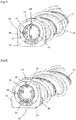
- the locking members 18 are configured to protrude radially from the outer periphery 21 of the stopper body 17 when the locking members 18 occupy the locking position (see figures 9 and 11 ), and are configured to be located set back from or to be substantially flush with the outer periphery 21 of the stopper body 17 when the locking members 18 occupy the release position (see figures 7 and 10 ).
- the locking members 18 and the stopper body 17 are stationary in rotation relative to the receiving housing 9 when the stopper body 17 is locked on the main body 4.
- the closure cap 16 also includes an actuator 22 which is configured to move the locking members 18 between the locked position and the released position.
- the actuator 22 may for example have the general shape of a disc.
- the actuating member 22 is mounted to be movable in rotation relative to the stopper body 17, about an actuation axis which is substantially coaxial with the axis of rotation A of the rotating brush 12, between a first actuation position (see figure 7 ) and a second actuation position (see figure 8 ), and the actuator 22 and the locking members 18 are configured such that a movement of the actuator 22 from the first actuation position to the second actuation position causes a displacement locking members 18 from the release position to the locking position and such that a movement of the actuator 22 from the second actuation position to the first actuation position causes a displacement of the members locking device 18 from the locked position to the released position.
- Such a configuration of the closure cap 16 allows locking / unlocking of the cap body 17 only by moving the actuator 22 between the first and second actuation positions, which ensures easy and ergonomic removal of the rotating brush. 12 outside the reception area 9.
- the actuator 22 comprises at least a cam groove 23, advantageously three cam grooves 23, in each of which is received a lug 24 provided on a respective locking member 18.
- Each cam groove 23 extends transversely to the axis of rotation A of the rotating brush 12.
- each cam groove 23 is curved and has the general shape of an arc of a circle.
- Each cam groove 23 may have a constant radius of curvature or a progressive radius of curvature.
- each cam groove 23 could however be rectilinear.
- Each cam groove 23 has a first cam surface 23.1 which is configured to move the respective locking member 18 from the release position to the locking position when the actuator 22 is rotatably moved from the first position. actuation to the second actuation position, and a second cam surface 23.2 which is configured to move the respective latch member 18 from the latch position to the release position when the actuator 22 is moved in rotation from the second actuation position to the first actuation position.
- each lug 24 is in sliding contact, alternately or simultaneously, on the first and second cam surfaces 23.1, 23.2 formed by the respective cam groove 23 such that when the actuator 22 is moved between the first actuation position and the second actuation position, said lug 24 moves relative to the respective cam groove 23 by sliding on the first and second cam surfaces 23.1, 23.2 and causes displacement of the member respective locking 18 between the release position and the locking position.
- the closure cap 16 further comprises a gripping handle 25 configured to be gripped by a user, for example to allow removal of the rotating brush 12 from the receiving housing 9.
- the gripping handle 25 may for example have a shape semicircular or any other shape.
- the gripping handle 25 is pivotally mounted on the actuator 22 between a rest position (see figure 8 ) and a gripping position (see figure 7 ) around a pivot axis which is substantially perpendicular to the axis of rotation A of the rotating brush 12.
- the gripping handle 25 and the actuating member 22 are more particularly configured to delimit, when the gripping handle 25 occupies the gripping position, a gripping passage suitable for receiving at least one finger of a user.
- the closing cap 16 advantageously the actuator 22, comprises a handle housing 22.1 formed by a cavity of the closing cap 16, advantageously of the actuator 22. , in which the grip handle 25 extends at least partially when the grip handle 25 occupies the rest position.
- the gripping handle 25 in the rest position of the gripping handle 25, is housed in the handle housing 22.1 and is arranged to be substantially flush with or set back from an outer surface of the closure cap 16, for example an outer surface 22.2 of the actuator (see figure 9 ), which surrounds the cavity forming the handle housing 22.1.
- the grip handle 25 may include a grip projection (not shown) which projects out of the grip housing 22.1 when the grip handle 25 occupies the rest position and which is configured to be gripped by a user when the gripping handle 25 occupies the rest position so as to be able to move the gripping handle 25 from the rest position to the gripping position.
- a grip projection (not shown) which projects out of the grip housing 22.1 when the grip handle 25 occupies the rest position and which is configured to be gripped by a user when the gripping handle 25 occupies the rest position so as to be able to move the gripping handle 25 from the rest position to the gripping position.
- the gripping handle 25 is more particularly configured to move the actuating member 22 from the first actuating position to the second actuating position when a first torque is applied to the gripping handle 25 by a user. in a first direction of rotation, and to move the actuator 22 from the second actuation position to the first actuation position when a second torque is applied on the gripping handle 25 by a user in a second direction of rotation opposite to the first direction of rotation.
- the closure cap 16 comprises a fixing cover 26 which is fixed to the stopper body 17.
- the fixing cover 26 and the stopper body 17 define a mounting housing in which is mounted the actuator 22, and are configured to allow only a rotational movement of the actuator 22 relative to the stopper body 17.
- the fixing cover 26 is annular, extends around of the actuator 22 and partially covers the actuator 22.
- the actuator 22 comprises a reading mark 27 and the fixing cover comprises a locking mark 28 and a release mark 29 which are angularly offset with respect to the axis of rotation A of the rotating brush 12.
- the reading mark 27 is configured to be located opposite the release mark 29 when the actuator 22 occupies the first actuation position and to be located opposite the reference mark. locking 28 when the actuator 22 occupies the second actuation position.
- the suction head 2 comprises a foolproofing device 31 configured to impose a relative angular orientation between the closure plug 16 and the main body 4 when inserting the plug body 17 into the passage opening 13.
- the coding device comprises a pair of coding elements 32, such as two coding ribs, provided on the stopper body 17, and the passage opening 13 has a non-circular shape.
- the suction head 2 also comprises a drive device 33 configured to drive the rotating brush 12 in rotation around the axis of rotation A of the latter.
- the drive device 33 more particularly comprises an electric drive motor 34, the output axis of which can be substantially aligned with the axis of rotation A of the rotating brush 12.
- the electric drive motor 34 is housed in the brush body 14 of the rotating brush 12.
- the electric drive motor 34 could be offset with respect to the axis of rotation A of the rotating brush 12.
- the rotating brush 12 comprises a first end portion 12.1 configured to be coupled in rotation to the drive device 33, and a second end portion 12.2 supported by the closure cap 16 and mounted to be movable in rotation by in relation to the closure cap 16.
- the drive device 33 comprises a coupling member 35 which is integral in rotation with the output shaft of the electric drive motor 33 and which is rotatably coupled with the first end portion 12.1 of the rotating brush 12.
- the user moves the gripping handle 25 into the gripping position and applies a rotational torque to the handle. gripping 25 so as to move the actuator 22 into the first actuation position. Such a movement of the actuating member 22 causes a movement of the locking members 18 in the released position. The user can then easily remove the rotating brush 12 from the receiving housing 9 by exerting a pulling force on the gripping handle 25 in order to clean or replace the rotating brush 12.
Landscapes
- Engineering & Computer Science (AREA)
- Mechanical Engineering (AREA)
- Nozzles For Electric Vacuum Cleaners (AREA)
Abstract
L'unité de nettoyage (11) comprend une brosse rotative (12) qui est configurée pour être montée de manière amovible dans un logement de réception d'une tête d'aspiration, et un bouchon de fermeture (16) qui est configuré pour fermer une ouverture de passage (13) à travers laquelle la brosse rotative (12) est apte à être introduite dans et retirée hors du logement de réception, le bouchon de fermeture (16) comportant une poignée de préhension (25) qui est mobile entre une position de repos et une position de préhension dans laquelle la poignée de préhension est configurée pour être saisie par un utilisateur de manière à pouvoir manipuler le bouchon de fermeture.The cleaning unit (11) includes a rotating brush (12) which is configured to be removably mounted in a housing for receiving a suction head, and a closure plug (16) which is configured to close. a passage opening (13) through which the rotating brush (12) is adapted to be introduced into and withdrawn out of the receiving housing, the closure plug (16) having a gripping handle (25) which is movable between a rest position and a gripping position in which the gripping handle is configured to be gripped by a user so as to be able to manipulate the closure cap.
Description
La présente invention concerne le domaine des aspirateurs équipés d'une tête d'aspiration permettant d'aspirer les poussières et les déchets de faible granulométrie présents sur une surface à nettoyer.The present invention relates to the field of vacuum cleaners equipped with a suction head for sucking up dust and small particle size waste present on a surface to be cleaned.
Les aspirateurs équipés d'une tête d'aspiration sont bien connus sur le marché, ceux-ci permettant de nettoyer des surfaces par aspiration pour l'évacuation des poussières et des déchets de faible granulométrie reposant sur celles-ci. La surface à aspirer peut par exemple être du carrelage, du parquet, du stratifié, de la moquette ou un tapis.Vacuum cleaners equipped with a suction head are well known on the market, the latter making it possible to clean surfaces by suction for the removal of dust and small-grain waste based thereon. The surface to be vacuumed can, for example, be tiles, parquet, laminate, carpet or a rug.
Une tête d'aspiration comprend de façon connue un corps principal comportant une semelle munie d'une face inférieure et d'un orifice d'aspiration débouchant dans la face inférieure de la semelle. La face inférieure de la semelle est destinée à être positionnée de manière attenante à la surface à aspirer durant l'utilisation de la tête d'aspiration.A suction head comprises, in a known manner, a main body comprising a sole provided with a lower face and with a suction orifice opening into the lower face of the sole. The underside of the sole is intended to be positioned adjacent to the surface to be vacuumed during use of the vacuum head.
Afin d'améliorer les performances de nettoyage d'une tête d'aspiration, il est connu d'équiper cette dernière d'une unité de nettoyage comprenant :
- une brosse rotative qui est mobile en rotation autour d'un axe de rotation et qui est montée de manière amovible dans un logement de réception délimité par le corps principal de la tête d'aspiration, et
- un bouchon de fermeture qui est configuré pour fermer au moins partiellement une ouverture de passage prévue sur le corps principal et à travers laquelle la brosse rotative est apte à être introduite dans et retirée hors du logement de réception, la brosse rotative étant rotative par rapport au bouchon de fermeture.
- a rotating brush which is movable in rotation about an axis of rotation and which is removably mounted in a receiving housing delimited by the main body of the suction head, and
- a closure plug which is configured to at least partially close a passage opening provided on the main body and through which the rotating brush is adapted to be introduced into and withdrawn out of the receiving housing, the rotating brush being rotatable relative to the closing cap.
Afin de permettre une manipulation du bouchon de fermeture par un utilisateur, notamment lors d'un retrait de la brosse rotative en vue par exemple de son nettoyage, il est connu d'équiper le bouchon de fermeture de deux ailettes de préhension qui sont diamétralement opposées par rapport à l'axe de rotation de la brosse rotative et qui font saillie depuis une surface frontale du bouchon de fermeture.In order to allow manipulation of the closure plug by a user, in particular when the rotating brush is withdrawn for example for cleaning, it is known practice to equip the closure plug with two gripping fins which are diametrically opposed. relative to the axis of rotation of the rotating brush and which protrude from a front surface of the closure cap.
Or, une telle configuration du bouchon de fermeture augmente l'encombrement du bouchon de fermeture et donc de l'unité de nettoyage, et peut induire un déverrouillage intempestif du bouchon de fermeture lors par exemple d'un impact du bouchon de fermeture contre un obstacle.However, such a configuration of the closing cap increases the size of the closing cap and therefore of the cleaning unit, and can induce an untimely unlocking of the closing cap during, for example, an impact of the closing cap against an obstacle. .
Afin de limiter l'encombrement du bouchon de fermeture, il peut être envisagé de diminuer les dimensions des deux ailettes de préhension, ce qui rend cependant malaisé la manipulation du bouchon de fermeture pour certains utilisateurs.In order to limit the size of the closure cap, it can be envisaged to reduce the dimensions of the two gripping fins, which however makes it difficult to handle the closure cap for some users.
La présente invention vise à remédier à tout ou partie de ces inconvénients.The present invention aims to remedy all or part of these drawbacks.
Le problème technique à la base de l'invention consiste notamment à fournir une unité de nettoyage pour tête d'aspiration assurant une manipulation aisée et ergonomique du bouchon de fermeture, tout en assurant un verrouillage fiable du bouchon de fermeture sur le corps principal de la tête d'aspiration.The technical problem underlying the invention consists in particular in providing a cleaning unit for a suction head ensuring easy and ergonomic handling of the closure cap, while ensuring reliable locking of the closure cap on the main body of the device. suction head.
A cet effet, la présente invention concerne une unité de nettoyage pour tête d'aspiration, comprenant :
- une brosse rotative qui est mobile en rotation autour d'un axe de rotation et qui est configurée pour être montée de manière amovible dans un logement de réception délimité par un corps principal de la tête d'aspiration, et
- un bouchon de fermeture qui est configuré pour fermer au moins partiellement une ouverture de passage prévue sur le corps principal et à travers laquelle la brosse rotative est apte à être introduite dans le logement de réception et retirée hors du logement de réception, la brosse rotative étant rotative par rapport au bouchon de fermeture.
- a rotating brush which is movable in rotation about an axis of rotation and which is configured to be removably mounted in a receiving housing delimited by a main body of the suction head, and
- a closure plug which is configured to at least partially close a passage opening provided on the main body and through which the rotating brush is adapted to be introduced into the receiving housing and withdrawn from the receiving housing, the rotating brush being rotatable relative to the closure cap.
Le bouchon de fermeture comporte une poignée de préhension qui est mobile entre une position de repos et une position de préhension dans laquelle la poignée de préhension est configurée pour être saisie par un utilisateur de manière à pouvoir manipuler le bouchon de fermeture, et par exemple de manière à pouvoir retirer la brosse rotative hors du logement de réception lorsque la brosse rotative est montée dans le logement de réception.The closure cap has a grip handle which is movable between a rest position and a grip position in which the grip handle is configured to be gripped by a user so that it can be gripped. manipulate the closure cap, and for example so as to be able to withdraw the rotating brush from the receiving housing when the rotating brush is mounted in the receiving housing.
Une telle configuration de la poignée de préhension assure notamment un retrait aisé et ergonomique de la brosse rotative hors du logement de réception lorsque la poignée de préhension occupe la position de préhension, tout en limitant l'encombrement du bouchon de fermeture et donc de l'unité de nettoyage sur la tête d'aspiration, lorsque la poignée de préhension occupe la position de repos. De plus, une telle configuration de la poignée de préhension, et en particulier le fait que la poignée de préhension occupe la position de repos en conditions normales d'utilisation de la tête d'aspiration, limite considérablement les risques de déverrouillage intempestif du bouchon de fermeture.Such a configuration of the gripping handle ensures in particular an easy and ergonomic removal of the rotating brush from the receiving housing when the gripping handle occupies the gripping position, while limiting the size of the closure cap and therefore of the cleaning unit on the suction head, when the gripping handle is in the rest position. In addition, such a configuration of the gripping handle, and in particular the fact that the gripping handle occupies the rest position in normal conditions of use of the suction head, considerably limits the risks of inadvertent unlocking of the suction head. closing.
L'unité de nettoyage peut en outre présenter une ou plusieurs des caractéristiques suivantes, prises seules ou en combinaison.The cleaning unit may further have one or more of the following characteristics, taken alone or in combination.
Selon un mode de réalisation de l'invention, la poignée de préhension est configurée pour délimiter, lorsque la poignée de préhension occupe la position de préhension, au moins partiellement un passage de préhension apte à recevoir au moins un doigt d'un utilisateur.According to one embodiment of the invention, the gripping handle is configured to delimit, when the gripping handle occupies the gripping position, at least partially a gripping passage capable of receiving at least one finger of a user.
Selon un mode de réalisation de l'invention, la poignée de préhension s'étend sensiblement dans un plan de repos lorsque la poignée de préhension occupe la position de repos, le plan de repos s'étendant transversalement, et par exemple sensiblement perpendiculairement, à l'axe de rotation de la brosse rotative.According to one embodiment of the invention, the gripping handle extends substantially in a rest plane when the gripping handle occupies the rest position, the rest plane extending transversely, and for example substantially perpendicularly, to the axis of rotation of the rotating brush.
Selon un mode de réalisation de l'invention, la poignée de préhension s'étend sensiblement dans un plan de préhension lorsque la poignée de préhension occupe la position de préhension, le plan de préhension s'étendant sensiblement parallèlement à l'axe de rotation de la brosse rotative.According to one embodiment of the invention, the gripping handle extends substantially in a gripping plane when the gripping handle occupies the gripping position, the gripping plane extending substantially parallel to the axis of rotation of the rotating brush.
Selon un mode de réalisation de l'invention, dans la position de repos de la poignée de préhension, la poignée de préhension est logée dans un logement de poigné formé par une cavité du bouchon de fermeture.According to one embodiment of the invention, in the rest position of the gripping handle, the gripping handle is housed in a handle housing formed by a cavity of the closing cap.
Selon un mode de réalisation de l'invention, dans la position de repos de la poignée de préhension, la poignée de préhension est logée dans un logement de poigné formé par une cavité du bouchon de fermeture et est arrangée pour sensiblement affleurer ou être en retrait d'une surface extérieure du bouchon de fermeture. Ladite surface extérieure entoure la cavité du bouchon. En d'autres termes, dans la position de repos la poignée de préhension est logée dans une cavité du bouchon de fermeture et est arrangée pour ne pas faire saillie, ou que très légèrement, au-delà de la surface extérieure du bouchon de fermeture qui entoure la cavité du bouchon de fermeture. En effet, du fait des tolérances d'assemblage et jeux de fonctionnement, dans la position de repos de la poignée de préhension, la poignée de préhension pourrait être légèrement en saillie, de l'ordre de quelques dixièmes de millimètres jusqu'à environ 1 mm, au-delà de la surface extérieure du bouchon de fermeture qui entoure la cavité du bouchon de fermeture. La terminologie « sensiblement affleurante » couvre donc une saillie inférieure à 1mm de la poignée de préhension en position de repos par rapport à la surface extérieure du bouchon de fermeture qui entoure la cavité du bouchon.According to one embodiment of the invention, in the rest position of the gripping handle, the gripping handle is housed in a handle housing formed by a cavity of the closure plug and is arranged to be substantially flush with or recessed. an outer surface of the closure cap. Said outer surface surrounds the cavity of the plug. In other words, in the rest position the grip handle is housed in a cavity of the closure cap and is arranged not to protrude, or only very slightly, beyond the outer surface of the closure cap which surrounds the cavity of the closure cap. Indeed, due to assembly tolerances and operating clearances, in the rest position of the gripping handle, the gripping handle could be slightly protruding, of the order of a few tenths of a millimeter up to approximately 1. mm, beyond the outer surface of the closure cap which surrounds the cavity of the closure cap. The terminology “substantially flush” therefore covers a projection of less than 1 mm from the gripping handle in the rest position relative to the outer surface of the closure cap which surrounds the cavity of the cap.
Ainsi en position de repos, la poignée de préhension est discrète. Cette construction limite le risque d'accrochage inopiné de la poignée lorsque la tête d'aspiration en déplacement sur le sol à aspirer.Thus in the rest position, the gripping handle is discreet. This construction limits the risk of the handle catching unexpectedly when the suction head moving on the floor to be sucked.
Dans une variante au mode de réalisation juste précité, dans la position de repos de la poignée de préhension, la poignée de préhension est logée dans un logement de poigné formé par une cavité du bouchon de fermeture et est arrangée pour sensiblement affleurer ou être en retrait d'une surface extérieure du bouchon de fermeture qui entoure la cavité du bouchon de fermeture, à l'exception d'une saillie de préhension de la poignée de préhension qui est configurée pour être saisie par un utilisateur lorsque la poignée de préhension occupe la position de repos de manière à pourvoir déplacer la poignée de préhension de la position de repos à la position de préhension.In a variant of the embodiment just mentioned above, in the rest position of the gripping handle, the gripping handle is housed in a handle housing formed by a cavity of the closure cap and is arranged to be substantially flush with or recessed. an exterior surface of the closure plug which surrounds the cavity of the closure plug, except for a gripping protrusion of the grip handle which is configured to be gripped by a user when the grip handle occupies the position rest so as to be able to move the gripping handle from the rest position to the gripping position.
Selon un mode de réalisation de l'invention, la poignée de préhension est montée pivotante entre la position de repos et la position de préhension autour d'un axe de pivotement.According to one embodiment of the invention, the gripping handle is pivotally mounted between the rest position and the gripping position about a pivot axis.
Selon un mode de réalisation de l'invention, l'axe de pivotement de la poignée de préhension est sensiblement perpendiculaire à l'axe de rotation de la brosse rotative.According to one embodiment of the invention, the pivot axis of the gripping handle is substantially perpendicular to the axis of rotation of the rotary brush.
Selon un mode de réalisation de l'invention, le bouchon de fermeture comporte un corps de bouchon et des moyens de verrouillage configurés pour verrouiller le corps de bouchon sur le corps principal.According to one embodiment of the invention, the closure cap comprises a cap body and locking means configured to lock the cap body on the main body.
Selon un mode de réalisation de l'invention, les moyens de verrouillage comportent au moins un organe de verrouillage qui est mobile par rapport au corps de bouchon entre une position de verrouillage dans laquelle l'au moins un organe de verrouillage coopère avec au moins un élément de verrouillage prévu sur le corps principal de manière à empêcher un retrait de la brosse rotative hors du logement de réception et une position de libération dans laquelle l'au moins un organe de verrouillage libère l'au moins un élément de verrouillage de manière à autoriser un retrait de la brosse rotative hors du logement de réception.According to one embodiment of the invention, the locking means comprise at least one locking member which is movable relative to the stopper body between a locking position in which the at least one locking member cooperates with at least one locking member provided on the main body so as to prevent a withdrawal of the rotating brush from the receiving housing and a release position in which the at least one locking member releases the at least one locking member so as to allow removal of the rotating brush from the receiving housing.
Une telle configuration du bouchon de fermeture garantit un verrouillage aisé et ergonomique du corps de bouchon sur le corps principal de la tête d'aspiration. En outre, une telle configuration du bouchon de fermeture assure un maintien efficace du corps de bouchon dans l'ouverture de passage et donc de la brosse rotative dans le logement de réception, et limite sensiblement la génération de vibrations par la brosse rotative lors de la rotation de cette dernière. De ce fait, l'unité de nettoyage selon la présente invention limite grandement le transfert de vibrations de la brosse rotative au corps principal de la tête d'aspiration, et assure un confort d'utilisation accru pour un utilisateur.Such a configuration of the closure cap guarantees easy and ergonomic locking of the cap body on the main body of the suction head. In addition, such a configuration of the closure cap ensures effective retention of the cap body in the passage opening and therefore of the rotating brush in the receiving housing, and substantially limits the generation of vibrations by the rotating brush during the rotation of the latter. Therefore, the cleaning unit according to the present invention greatly limits the transfer of vibrations from the rotating brush to the main body of the suction head, and provides increased convenience for a user.
Selon un mode de réalisation de l'invention, l'au moins un organe de verrouillage est mobile par rapport au corps de bouchon selon une direction de déplacement qui s'étend transversalement à l'axe de rotation de la brosse rotative.According to one embodiment of the invention, at least one locking member is movable relative to the stopper body in a direction of movement which extends transversely to the axis of rotation of the rotating brush.
Selon un mode de réalisation de l'invention, la direction de déplacement de l'au moins un organe de verrouillage est sensiblement radiale par rapport à l'axe de rotation de la brosse rotative.According to one embodiment of the invention, the direction of movement of the at least one locking member is substantially radial with respect to the axis of rotation of the rotating brush.
Selon un mode de réalisation de l'invention, la brosse rotative est configurée pour être montée de manière amovible dans un logement de réception selon une direction de montage qui s'étend transversalement, et de préférence perpendiculairement, à une direction de déplacement de la tête d'aspiration.According to one embodiment of the invention, the rotating brush is configured to be removably mounted in a receiving housing in a mounting direction which extends transversely, and preferably perpendicularly, to a direction of movement of the head. suction.
Selon un mode de réalisation de l'invention, l'au moins un organe de verrouillage est un pêne de verrouillage.According to one embodiment of the invention, the at least one locking member is a locking bolt.
Selon un mode de réalisation de l'invention, l'axe de rotation de la brosse rotative est sensiblement confondu avec un axe central de la brosse rotative.According to one embodiment of the invention, the axis of rotation of the rotating brush is substantially coincident with a central axis of the rotating brush.
Selon un mode de réalisation de l'invention, l'au moins un organe de verrouillage est configuré pour faire saillie radialement d'une périphérie externe du corps de bouchon lorsque l'au moins un organe de verrouillage occupe la position de verrouillage.According to one embodiment of the invention, the at least one locking member is configured to protrude radially from an outer periphery of the stopper body when the at least one locking member occupies the locking position.
Selon un mode de réalisation de l'invention, l'au moins un organe de verrouillage est configuré pour être situé en retrait de ou pour sensiblement affleurer la périphérie externe du corps de bouchon lorsque l'au moins un organe de verrouillage occupe la position de libération.According to one embodiment of the invention, the at least one locking member is configured to be situated set back from or to be substantially flush with the outer periphery of the stopper body when the at least one locking member occupies the position of. release.
Selon un mode de réalisation de l'invention, l'au moins un organe de verrouillage est monté coulissant par rapport au corps de bouchon.According to one embodiment of the invention, the at least one locking member is mounted to slide relative to the stopper body.
Selon un mode de réalisation de l'invention, le bouchon de fermeture comporte un organe d'actionnement qui est configuré pour déplacer l'au moins un organe de verrouillage entre la position de verrouillage et la position de libération.According to one embodiment of the invention, the closure cap comprises an actuating member which is configured to move the at least one locking member between the locking position and the release position.
Selon un mode de réalisation de l'invention, l'organe d'actionnement est actionnable manuellement depuis l'extérieur de la tête d'aspiration lorsque le corps de bouchon est verrouillé sur le corps principal.According to one embodiment of the invention, the actuating member can be actuated manually from outside the suction head when the stopper body is locked on the main body.
Selon un mode de réalisation de l'invention, l'organe d'actionnement est monté mobile par rapport au corps de bouchon entre une première position d'actionnement et une deuxième position d'actionnement, l'organe d'actionnement et l'au moins un organe de verrouillage étant configurés de telle sorte qu'un déplacement de l'organe d'actionnement de la première position d'actionnement à la deuxième position d'actionnement entraîne un déplacement de l'au moins un organe de verrouillage de la position de libération à la position de verrouillage et de telle sorte qu'un déplacement de l'organe d'actionnement de la deuxième position d'actionnement à la première position d'actionnement entraîne un déplacement de l'au moins un organe de verrouillage de la position de verrouillage à la position de libération. Une telle configuration du bouchon de fermeture permet un verrouillage/déverrouillage du corps de bouchon uniquement en déplaçant l'organe d'actionnement entre les première et deuxième positions d'actionnement, ce qui assure un retrait aisé et ergonomique de la brosse rotative hors du logement de réception.According to one embodiment of the invention, the actuating member is mounted movably relative to the stopper body between a first actuation position and a second actuation position, the actuation member and the at least one locking member being configured such that a movement of the member d 'actuation from the first actuation position to the second actuation position causes a displacement of the at least one locking member from the release position to the locking position and such that a displacement of the member actuation from the second actuation position to the first actuation position causes a displacement of the at least one locking member from the locking position to the release position. Such a configuration of the closure cap allows locking / unlocking of the cap body only by moving the actuator between the first and second actuation positions, which ensures easy and ergonomic removal of the rotating brush from the housing. reception.
Une telle configuration contribue aussi à assurer un verrouillage fiable indépendant de la force exercée par l'utilisateur pour verrouiller le bouchon de fermeture.Such a configuration also helps to ensure reliable locking independent of the force exerted by the user to lock the closure cap.
Selon un mode de réalisation de l'invention, l'organe d'actionnement est monté mobile en rotation autour d'un axe d'actionnement qui est sensiblement parallèle à l'axe de rotation de la brosse rotative.According to one embodiment of the invention, the actuating member is mounted to be movable in rotation about an actuation axis which is substantially parallel to the axis of rotation of the rotating brush.
Selon un mode de réalisation de l'invention, l'axe d'actionnement est sensiblement coaxial avec l'axe de rotation.According to one embodiment of the invention, the actuation axis is substantially coaxial with the axis of rotation.
Selon un mode de réalisation de l'invention, l'organe d'actionnement a une forme générale de disque.According to one embodiment of the invention, the actuating member has the general shape of a disc.
Selon un mode de réalisation de l'invention, l'organe d'actionnement comporte au moins une surface de came sur laquelle une partie de l'au moins un organe de verrouillage est en contact.According to one embodiment of the invention, the actuating member comprises at least one cam surface on which part of the at least one locking member is in contact.
Selon un mode de réalisation de l'invention, l'organe d'actionnement comporte au moins une rainure de came dans laquelle est formée l'au moins une surface de came, et la partie de l'au moins un organe de verrouillage, qui est en contact sur l'au moins une surface de came, est un ergot qui est prévu sur l'au moins un organe de verrouillage et qui est reçu dans l'au moins une rainure de came.According to one embodiment of the invention, the actuating member comprises at least one cam groove in which the at least one cam surface is formed, and the part of the at least one locking member, which is in contact on at least a cam surface, is a lug which is provided on the at least one locking member and which is received in the at least one cam groove.
Avantageusement, l'ergot est en contact glissant sur l'au moins une surface de came de telle sorte que, lorsque l'organe d'actionnement est déplacé entre la première position d'actionnement et la deuxième position d'actionnement, l'ergot se déplace par rapport à l'au moins une rainure de came en glissant sur l'au moins une surface de came et entraîne un déplacement de l'au moins un organe de verrouillage entre la position de libération et la position de verrouillage.Advantageously, the lug is in sliding contact on the at least one cam surface such that, when the actuator member is moved between the first actuation position and the second actuation position, the lug moves relative to the at least one cam groove by sliding over the at least one cam surface and causes movement of the at least one locking member between the released position and the locked position.
Selon un mode de réalisation de l'invention, l'au moins une rainure de came s'étend transversalement à l'axe de rotation de la brosse rotative.According to one embodiment of the invention, the at least one cam groove extends transversely to the axis of rotation of the rotating brush.
Selon un mode de réalisation de l'invention, l'au moins une surface de came, de préférence l'au moins une rainure de came, est courbée. L'au moins une surface de came, de préférence l'au moins une rainure de came, peut par exemple avoir une forme en arc de cercle ou présenter un rayon de courbure progressif.According to one embodiment of the invention, the at least one cam surface, preferably the at least one cam groove, is curved. The at least one cam surface, preferably the at least one cam groove, can for example have the shape of an arc of a circle or have a progressive radius of curvature.
Selon un mode de réalisation de l'invention, l'au moins une surface de came, de préférence l'au moins une rainure de came, est sensiblement rectiligne.According to one embodiment of the invention, the at least one cam surface, preferably the at least one cam groove, is substantially rectilinear.
Selon un mode de réalisation de l'invention, l'au moins une rainure de came comporte une première surface de came qui est configurée pour déplacer l'au moins un organe de verrouillage de la position de libération vers la position de verrouillage lorsque l'organe d'actionnement est déplacé de la première position d'actionnement vers la deuxième position d'actionnement, et une deuxième surface de came qui est configurée pour déplacer l'au moins un organe de verrouillage de la position de verrouillage vers la position de libération lorsque l'organe d'actionnement est déplacé de la deuxième position d'actionnement vers la première position d'actionnement.According to one embodiment of the invention, the at least one cam groove has a first cam surface which is configured to move the at least one locking member from the release position to the locking position when the actuator is moved from the first actuation position to the second actuation position, and a second cam surface which is configured to move the at least one locking member from the locked position to the release position when the actuator is moved from the second actuation position to the first actuation position.
Selon un mode de réalisation de l'invention, la poignée de préhension est montée mobile sur l'organe d'actionnement. Ces dispositions permettent de faciliter le verrouillage/déverrouillage du corps de bouchon sur le corps principal de la tête d'aspiration.According to one embodiment of the invention, the gripping handle is movably mounted on the actuating member. These arrangements make it possible to facilitate the locking / unlocking of the stopper body on the main body of the suction head.
Selon un mode de réalisation de l'invention, la poignée de préhension est configurée pour déplacer l'organe d'actionnement entre la première position d'actionnement et la deuxième position d'actionnement lorsque la poignée de préhension est actionnée par un utilisateur.According to one embodiment of the invention, the gripping handle is configured to move the actuating member between the first actuation position and the second actuation position when the gripping handle is actuated by a user.
Selon un mode de réalisation de l'invention, la poignée de préhension est configurée pour transmettre un couple de rotation à l'organe d'actionnement.According to one embodiment of the invention, the gripping handle is configured to transmit a torque to the actuator.
Selon un mode de réalisation de l'invention, la poignée de préhension est configurée pour déplacer l'organe d'actionnement de la première position d'actionnement vers la deuxième position d'actionnement lorsqu'un premier couple de rotation est appliqué sur la poignée de préhension par un utilisateur dans un premier sens de rotation, et pour déplacer l'organe d'actionnement de la deuxième position d'actionnement vers la première position d'actionnement lorsqu'un deuxième couple de rotation est appliqué sur la poignée de préhension par un utilisateur dans un deuxième sens de rotation opposé au premier sens de rotation.According to one embodiment of the invention, the gripping handle is configured to move the actuator from the first actuation position to the second actuation position when a first torque is applied to the grip. gripping by a user in a first direction of rotation, and for moving the actuator from the second actuation position to the first actuation position when a second torque is applied to the gripping handle by a user in a second direction of rotation opposite to the first direction of rotation.
Selon un mode de réalisation de l'invention, le bouchon de fermeture comporte un capot de fixation qui est fixé au corps de bouchon et qui recouvre partiellement l'organe d'actionnement. Le capot de fixation et le corps de bouchon délimitent avantageusement un logement de montage dans lequel est monté l'organe d'actionnement. Le capot de fixation peut par exemple être annulaire.According to one embodiment of the invention, the closure cap comprises a fixing cover which is fixed to the stopper body and which partially covers the actuating member. The fixing cover and the stopper body advantageously define a mounting housing in which the actuator is mounted. The fixing cover can for example be annular.
Selon un mode de réalisation de l'invention, l'organe d'actionnement comporte un repère de lecture et le bouchon de fermeture comporte un repère de verrouillage et un repère de libération qui sont décalés angulairement par rapport à l'axe de rotation de la brosse rotative et qui sont immobiles en rotation par rapport au corps de bouchon, le repère de lecture étant configuré pour être situé en regard du repère de libération lorsque l'organe d'actionnement occupe la première position d'actionnement et pour être situé en regard du repère de verrouillage lorsque l'organe d'actionnement occupe la deuxième position d'actionnement. De façon avantageuse, le repère de verrouillage et le repère de libération sont prévus sur le capot de fixation.According to one embodiment of the invention, the actuating member comprises a reading mark and the closure cap comprises a locking mark and a release mark which are angularly offset with respect to the axis of rotation of the rotating brush and which are stationary in rotation with respect to the stopper body, the reading mark being configured to be located opposite the release mark when the actuating member occupies the first actuating position and to be located opposite of the locking mark when the actuating member occupies the second actuating position. Advantageously, the locking mark and the release mark are provided on the fixing cover.
Selon un mode de réalisation de l'invention, la brosse rotative comporte un corps de brosse qui est tubulaire. De façon avantageuse, le corps de brosse est cylindrique à section circulaire.According to one embodiment of the invention, the rotating brush comprises a brush body which is tubular. Advantageously, the brush body is cylindrical with a circular section.
Selon un mode de réalisation de l'invention, la brosse rotative est guidée en rotation dans ou autour du corps de bouchon.According to one embodiment of the invention, the rotating brush is guided in rotation in or around the stopper body.
Selon un mode de réalisation de l'invention, la brosse rotative comporte des poils prévus sur la surface externe du corps de brosse. De façon avantageuse, la brosse rotative comporte au moins une rangée de poils prévues sur la surface externe du corps de brosse.According to one embodiment of the invention, the rotating brush comprises bristles provided on the outer surface of the brush body. Advantageously, the rotating brush comprises at least one row of bristles provided on the outer surface of the brush body.
Selon un mode de réalisation de l'invention, les moyens de verrouillage comportent une pluralité d'organes de verrouillage qui sont décalés angulairement les uns des autres par rapport à l'axe de rotation de la brosse rotative.According to one embodiment of the invention, the locking means comprise a plurality of locking members which are angularly offset from each other with respect to the axis of rotation of the rotating brush.
Selon un mode de réalisation de l'invention, les moyens de verrouillage comportent trois organes de verrouillage.According to one embodiment of the invention, the locking means comprise three locking members.
Selon un mode de réalisation de l'invention, les organes de verrouillage sont régulièrement répartis autour de l'axe de rotation de la brosse rotative.According to one embodiment of the invention, the locking members are regularly distributed around the axis of rotation of the rotating brush.
La présente invention concerne en outre une tête d'aspiration comprenant :
- un corps principal comportant un logement de réception débouchant dans une face inférieure du corps principal qui est configurée pour être orientée vers une surface à nettoyer, et une ouverture de passage débouchant dans le logement de réception, et
- une unité de nettoyage selon la présente invention, la brosse rotative étant montée de manière amovible dans le logement de réception et le bouchon de fermeture fermant au moins partiellement l'ouverture de passage.
- a main body comprising a receiving housing opening into a lower face of the main body which is configured to be oriented towards a surface to be cleaned, and a passage opening opening into the receiving housing, and
- a cleaning unit according to the present invention, the rotating brush being removably mounted in the receiving housing and the closure plug at least partially closing the passage opening.
Selon un mode de réalisation de l'invention, l'au moins un élément de verrouillage comporte au moins une rainure de verrouillage dans laquelle l'au moins un organe de verrouillage est configuré pour s'engager lorsque l'au moins un organe de verrouillage occupe la position de verrouillage. De façon avantageuse, l'au moins une rainure de verrouillage s'étend au moins en partie autour de l'ouverture de passage.According to one embodiment of the invention, the at least one locking element comprises at least one locking groove in which the at least one locking member is configured to engage when the at least one locking member occupies the locked position. Advantageously, the at least one locking groove extends at least in part around the passage opening.
Selon un mode de réalisation de l'invention, l'au moins un élément de verrouillage comporte une pluralité de rainures de verrouillage qui sont décalées angulairement les unes des autres par rapport à l'axe de rotation de la brosse rotative et dans chacune desquelles est destiné à être reçu un organe de verrouillage respectif.According to one embodiment of the invention, the at least one locking element comprises a plurality of locking grooves which are angularly offset from each other with respect to the axis of rotation of the rotating brush and in each of which is intended to be received by a respective locking member.
Selon un mode de réalisation de l'invention, l'au moins un organe de verrouillage et le corps de bouchon sont immobiles en rotation par rapport au logement de réception lorsque le corps de bouchon est verrouillé sur le corps principal.According to one embodiment of the invention, the at least one locking member and the stopper body are stationary in rotation with respect to the receiving housing when the stopper body is locked on the main body.
Selon un mode de réalisation de l'invention, la tête d'aspiration comporte un dispositif de détrompage configuré pour imposer une orientation angulaire relative entre le bouchon de fermeture et le corps principal lors d'une insertion du corps de bouchon dans l'ouverture de passage.According to one embodiment of the invention, the suction head comprises a keying device configured to impose a relative angular orientation between the closure cap and the main body during insertion of the cap body in the opening of passage.
Selon un mode de réalisation de l'invention, le dispositif de détrompage comporte au moins un élément de détrompage, tel qu'une nervure de détrompage, prévu sur le bouchon de fermeture, et au moins un organe de détrompage, tel qu'une rainure de détrompage, prévu sur le corps principal.According to one embodiment of the invention, the coding device comprises at least one coding element, such as a coding rib, provided on the closure cap, and at least one coding member, such as a groove keying, provided on the main body.
Selon le mode de réalisation de l'invention, l'ouverture de passage est prévue sur une face latérale du corps principal.According to the embodiment of the invention, the passage opening is provided on a lateral face of the main body.
Selon un mode de réalisation de l'invention, la tête d'aspiration comporte un dispositif d'entraînement configuré pour entraîner en rotation la brosse rotative autour de l'axe de rotation.According to one embodiment of the invention, the suction head comprises a drive device configured to drive the rotating brush in rotation about the axis of rotation.
Selon un mode de réalisation de l'invention, la brosse rotative comporte une première portion d'extrémité configurée pour être couplée en rotation au dispositif d'entraînement, et une deuxième portion d'extrémité supportée par le bouchon de fermeture et montée mobile en rotation par rapport au bouchon de fermeture.According to one embodiment of the invention, the rotating brush comprises a first end portion configured to be coupled in rotation to the drive device, and a second end portion supported by the closure cap and mounted to be movable in rotation. in relation to the closing cap.
Selon un mode de réalisation de l'invention, le dispositif d'entraînement comporte un moteur d'entraînement dont l'axe de sortie peut être sensiblement aligné avec l'axe de rotation de la brosse rotative ou être décalé par rapport l'axe de rotation de la brosse rotative.According to one embodiment of the invention, the drive device comprises a drive motor, the output axis of which can be substantially aligned with the axis of rotation of the rotating brush or be offset from the axis of rotation of the rotating brush.
Selon un mode de réalisation de l'invention, le corps principal comprend une semelle munie de la face inférieure qui est configurée pour être orientée vers la surface à nettoyer, et d'un orifice d'aspiration débouchant dans la face inférieure. De façon avantageuse, le logement de réception débouche dans la face inférieure de la semelle via l'orifice d'aspiration.According to one embodiment of the invention, the main body comprises a sole provided with the lower face which is configured to be oriented towards the surface to be cleaned, and with a suction port opening into the lower face. Advantageously, the receiving housing opens into the underside of the sole via the suction orifice.
Selon un mode de réalisation de l'invention, l'orifice d'aspiration présente une forme allongée et s'étend transversalement, et par exemple perpendiculairement, à la direction de déplacement de la tête d'aspiration.According to one embodiment of the invention, the suction orifice has an elongated shape and extends transversely, and for example perpendicularly, to the direction of movement of the suction head.
L'invention sera bien comprise à l'aide de la description qui suit en référence aux dessins schématiques annexés représentant, à titre d'exemple non limitatif, une forme d'exécution de cette tête d'aspiration .
- [
Fig 1 ] Lafigure 1 est une vue en perspective de dessus d'une tête d'aspiration selon la présente invention. - [
Fig 2 ] Lafigure 2 est une vue en perspective de dessus de la tête d'aspiration de lafigure 1 montrant une unité de nettoyage de la tête d'aspiration partiellement retirée. - [
Fig 3 ] Lafigure 3 est une vue partielle de côté de la tête d'aspiration de lafigure 1 , montrant un bouchon de verrouillage de l'unité de nettoyage en position verrouillée. - [
Fig 4 ] Lafigure 4 est une vue partielle de côté de la tête d'aspiration de lafigure 1 , montrant le bouchon de verrouillage en position déverrouillée. - [
Fig 5 ] Lafigure 5 est une vue en coupe longitudinale de la tête d'aspiration de lafigure 1 . - [
Fig 6 ] Lafigure 6 est une vue éclatée en perspective d'un bouchon de fermeture de l'unité de nettoyage de lafigure 2 . - [
Fig 7 ] Lafigure 7 est une vue en perspective de l'unité de nettoyage, montrant une poignée de préhension dans une position de préhension et des organes de verrouillage dans une position de libération. - [
Fig 8 ] Lafigure 8 est une vue en perspective de l'unité de nettoyage, montrant la poignée de préhension dans une position de repos et les organes de verrouillage dans une position de verrouillage. - [
Fig 9 ] Lafigure 9 est une vue avant en perspective du bouchon de fermeture, montrant les organes de verrouillage dans la position de verrouillage. - [
Fig 10 ] Lafigure 10 est une vue arrière en perspective du bouchon de fermeture, montrant les organes de verrouillage dans la position de libération. - [
Fig 11 ] Lafigure 11 est une vue arrière en perspective du bouchon de fermeture, montrant les organes de verrouillage dans la position de verrouillage.
- [
Fig 1 ] Thefigure 1 is a perspective view from above of a suction head according to the present invention. - [
Fig 2 ] Thefigure 2 is a perspective view from above of the suction head of thefigure 1 showing a partially removed suction head cleaning unit. - [
Fig 3 ] Thefigure 3 is a partial side view of the suction head of thefigure 1 , showing a locking cap of the cleaning unit in the locked position. - [
Fig 4 ] Thefigure 4 is a partial side view of the suction head of thefigure 1 , showing the locking cap in the unlocked position. - [
Fig 5 ] Thefigure 5 is a longitudinal sectional view of the suction head of thefigure 1 . - [
Fig 6 ] Thefigure 6 is an exploded perspective view of a closure cap for the cleaning unit of thefigure 2 . - [
Fig 7 ] Thefigure 7 is a perspective view of the cleaning unit, showing a gripping handle in a gripping position and locking members in a release position. - [
Fig 8 ] Thefigure 8 is a perspective view of the cleaning unit, showing the grip handle in a rest position and the locking members in a locking position. - [
Fig 9 ] Thefigure 9 is a front perspective view of the closure cap, showing the locking members in the locked position. - [
Fig 10 ] Thefigure 10 is a rear perspective view of the closure cap, showing the locking members in the released position. - [
Fig 11 ] Thefigure 11 is a rear perspective view of the closure cap, showing the locking members in the locked position.
Les
La tête d'aspiration 2 comprend un corps principal 4 configuré pour être déplacé sur une surface à nettoyer. Le manchon de raccordement 3 est avantageusement monté en liaison pivot par rapport au corps principal 4 de manière à permettre un pivotement du corps principal 4 vers l'avant et vers l'arrière lors d'un déplacement de la tête d'aspiration 2 selon une direction de déplacement D1.The
Le corps principal 4 comprend une semelle 5 munie d'une face inférieure 6 configurée pour être orientée vers la surface à nettoyer, et d'un orifice d'aspiration 7 débouchant sur la face inférieure 6. L'orifice d'aspiration 7 communique avec le manchon de raccordement 3 par le biais notamment d'un passage de liaison formé au moins en partie par exemple par un conduit de liaison flexible. L'orifice d'aspiration 7 peut par exemple présenter une forme allongée et s'étendre transversalement, et par exemple perpendiculairement, à la direction de déplacement D1 de la tête d'aspiration 2.The
Le corps principal 4 comprend en outre un logement de réception 9 qui débouche dans la face inférieure de la semelle 5 via l'orifice d'aspiration 7, et qui est relié fluidiquement au passage de liaison. Ainsi, selon le mode de réalisation représenté sur les figures, le logement de réception 9 forme une chambre d'aspiration.The
La tête d'aspiration 2 comprend également une unité de nettoyage 11 comportant une brosse rotative 12 qui est montée mobile en rotation dans le logement de réception 9 selon un axe de rotation A qui est sensiblement confondu avec l'axe central de la brosse rotative 12. De façon avantageuse, la brosse rotative 12 est montée de manière amovible dans le logement de réception 9 et configurée pour être introduite dans et retirée hors du logement de réception 9 selon une direction de montage D2. La direction de montage D2 s'étend transversalement, et de préférence perpendiculairement, à la direction de déplacement D1 de la tête d'aspiration 2.The
Selon le mode de réalisation représenté sur les figures, le corps principal 4 comporte une ouverture de passage 13 débouchant dans le logement de réception 9 et à travers laquelle la brosse rotative 12 peut être introduite dans et retirée hors du logement de réception 9. De façon avantageuse, l'ouverture de passage 13 est prévue sur une face latérale du corps principal 4.According to the embodiment shown in the figures, the
Selon le mode de réalisation représenté sur les figures, la brosse rotative 12 comporte un corps de brosse 14 qui est par exemple tubulaire, et des poils 15 prévus sur la surface externe du corps de brosse 14. De façon avantageuse, le corps de brosse 14 est cylindrique à section circulaire, et la brosse rotative 12 comporte une pluralité de rangées de poils s'étendant par exemple hélicoïdalement autour de l'axe central de la brosse rotative 12. Selon une variante de réalisation non représentée sur les figures, les rangées de poils pourraient être remplacées par des lamelles élastiquement déformables ou par un manchon de nettoyage en mousse.According to the embodiment shown in the figures, the rotating
L'unité de nettoyage 11 comporte en outre un bouchon de fermeture 16 qui est configuré pour fermer au moins partiellement l'ouverture de passage 13 lorsque la brosse rotative 12 est montée dans le logement de réception 9.The
Le bouchon de fermeture 16 comporte un corps de bouchon 17 et des moyens de verrouillage configurés pour verrouiller le corps de bouchon 17 sur le corps principal 4.The
Les moyens de verrouillage comportent au moins un organe de verrouillage 18, avantageusement trois organes de verrouillage 18, qui sont montés mobiles, de préférence coulissants, sur le corps de bouchon 17 entre une position de verrouillage dans laquelle les organes de verrouillage 18 coopèrent avec au moins un élément de verrouillage prévu sur le corps principal 4 de manière à empêcher un retrait de la brosse rotative 12 hors du logement de réception 9 et une position de libération dans laquelle les organes de verrouillage 18 libèrent l'au moins un élément de verrouillage de manière à autoriser un retrait de la brosse rotative 12 hors du logement de réception 9. Chaque organe de verrouillage 18 est avantageusement un pêne de verrouillage.The locking means comprise at least one locking
Selon un mode de réalisation de l'invention, l'au moins un élément de verrouillage comporte uniquement une rainure de verrouillage 19 s'étendant au moins en partie autour de l'ouverture de passage 13, et chaque organe de verrouillage 18 est configuré pour s'engager dans la rainure de verrouillage 19 lorsque les organes de verrouillage 18 occupent la position de verrouillage. Selon un autre mode de réalisation de l'invention, l'au moins un élément de verrouillage comporte une pluralité de rainures de verrouillage 19 qui sont décalées angulairement les unes des autres par rapport à l'axe de rotation A de la brosse rotative 12 et dans chacune desquelles est destiné à être reçu un organe de verrouillage 18 respectif.According to one embodiment of the invention, the at least one locking element comprises only one locking
Selon le mode de réalisation représenté sur les figures, les organes de verrouillage 18 sont régulièrement répartis autour de l'axe de rotation A de la brosse rotative 12, et chaque organe de verrouillage 18 est monté mobile par rapport au corps de bouchon 17 selon une direction de déplacement qui s'étend sensiblement radialement à l'axe de rotation A de la brosse rotative 12.According to the embodiment shown in the figures, the locking
Les organes de verrouillage 18 sont configurés pour faire saillie radialement de la périphérie externe 21 du corps de bouchon 17 lorsque les organes de verrouillage 18 occupent la position de verrouillage (voir les
De façon avantageuse, les organes de verrouillage 18 et le corps de bouchon 17 sont immobiles en rotation par rapport au logement de réception 9 lorsque le corps de bouchon 17 est verrouillé sur le corps principal 4.Advantageously, the locking
Le bouchon de fermeture 16 comporte également un organe d'actionnement 22 qui est configuré pour déplacer les organes de verrouillage 18 entre la position de verrouillage et la position de libération. L'organe d'actionnement 22 peut par exemple avoir une forme générale de disque.The
Selon le mode de réalisation représenté sur les figures, l'organe d'actionnement 22 est monté mobile en rotation par rapport au corps de bouchon 17, autour d'un axe d'actionnement qui est sensiblement coaxial avec l'axe de rotation A de la brosse rotative 12, entre une première position d'actionnement (voir la
Comme montré sur les
Selon le mode de réalisation représenté sur les figures, chaque rainure de came 23 est courbée et a une forme générale en arc de cercle. Chaque rainure de came 23 peut présenter un rayon de courbure constant ou un rayon de courbure progressif. Selon une variante de réalisation non représentée sur les figures, chaque rainure de came 23 pourrait toutefois être rectiligne.According to the embodiment shown in the figures, each
Chaque rainure de came 23 comporte une première surface de came 23.1 qui est configurée pour déplacer l'organe de verrouillage 18 respectif de la position de libération vers la position de verrouillage lorsque l'organe d'actionnement 22 est déplacé en rotation de la première position d'actionnement vers la deuxième position d'actionnement, et une deuxième surface de came 23.2 qui est configurée pour déplacer l'organe de verrouillage 18 respectif de la position de verrouillage vers la position de libération lorsque l'organe d'actionnement 22 est déplacé en rotation de la deuxième position d'actionnement vers la première position d'actionnement.Each
De façon avantageuse, chaque ergot 24 est en contact glissant, alternativement ou simultanément, sur les première et deuxième surfaces de came 23.1, 23.2 formée par la rainure de came 23 respective de telle sorte que, lorsque l'organe d'actionnement 22 est déplacé entre la première position d'actionnement et la deuxième position d'actionnement, ledit ergot 24 se déplace par rapport à la rainure de came 23 respective en glissant sur les première et deuxième surfaces de came 23.1, 23.2 et entraîne un déplacement de l'organe de verrouillage 18 respectif entre la position de libération et la position de verrouillage.Advantageously, each
Le bouchon de fermeture 16 comporte en outre une poignée de préhension 25 configurée pour être saisie par un utilisateur, par exemple pour permettre un retrait de la brosse rotative 12 hors du logement de réception 9. La poignée de préhension 25 peut par exemple présenter une forme semi-circulaire ou une toute autre forme.The
De façon avantageuse, la poignée de préhension 25 est montée pivotante sur l'organe d'actionnement 22 entre une position de repos (voir la
Selon le mode de réalisation représenté sur les figures, le bouchon de fermeture 16, avantageusement l'organe d'actionnement 22, comporte un logement de poignée 22.1 formé par une cavité du bouchon de fermeture 16, avantageusement de l'organe d'actionnement 22, dans lequel s'étend au moins partiellement la poignée de préhension 25 lorsque la poignée de préhension 25 occupe la position de repos.According to the embodiment shown in the figures, the
De façon avantageuse, dans la position de repos de la poignée de préhension 25, la poignée de préhension 25 est logée dans le logement de poignée 22.1 et est arrangée pour sensiblement affleurer ou être en retrait d'une surface extérieure du bouchon de fermeture 16, par exemple une surface extérieure 22.2 de l'organe d'actionnement (voir
De façon avantageuse, la poignée de préhension 25 peut comporter une saillie de préhension (non représentée) qui fait saillie hors du logement de poignée 22.1 lorsque la poignée de préhension 25 occupe la position de repos et qui est configurée pour être saisie par un utilisateur lorsque la poignée de préhension 25 occupe la position de repos de manière à pourvoir déplacer la poignée de préhension 25 de la position de repos à la position de préhension.Advantageously, the grip handle 25 may include a grip projection (not shown) which projects out of the grip housing 22.1 when the grip handle 25 occupies the rest position and which is configured to be gripped by a user when the
La poignée de préhension 25 est plus particulièrement configurée pour déplacer l'organe d'actionnement 22 de la première position d'actionnement vers la deuxième position d'actionnement lorsqu'un premier couple de rotation est appliqué sur la poignée de préhension 25 par un utilisateur dans un premier sens de rotation, et pour déplacer l'organe d'actionnement 22 de la deuxième position d'actionnement vers la première position d'actionnement lorsqu'un deuxième couple de rotation est appliqué sur la poignée de préhension 25 par un utilisateur dans un deuxième sens de rotation opposé au premier sens de rotation.The
Selon le mode de réalisation représenté sur les figures, le bouchon de fermeture 16 comporte un capot de fixation 26 qui est fixé au corps de bouchon 17. Le capot de fixation 26 et le corps de bouchon 17 délimitent un logement de montage dans lequel est monté l'organe d'actionnement 22, et sont configurés pour autoriser uniquement un mouvement de rotation de l'organe d'actionnement 22 par rapport au corps de bouchon 17. De façon avantageuse, le capot de fixation 26 est annulaire, s'étend autour de l'organe d'actionnement 22 et recouvre partiellement l'organe d'actionnement 22.According to the embodiment shown in the figures, the
Selon le mode de réalisation représenté sur les figures, l'organe d'actionnement 22 comporte un repère de lecture 27 et le capot de fixation comporte un repère de verrouillage 28 et un repère de libération 29 qui sont décalés angulairement par rapport à l'axe de rotation A de la brosse rotative 12. Le repère de lecture 27 est configuré pour être situé en regard du repère de libération 29 lorsque l'organe d'actionnement 22 occupe la première position d'actionnement et pour être situé en regard du repère de verrouillage 28 lorsque l'organe d'actionnement 22 occupe la deuxième position d'actionnement.According to the embodiment shown in the figures, the
La tête d'aspiration 2 comporte un dispositif de détrompage 31 configuré pour imposer une orientation angulaire relative entre le bouchon de fermeture 16 et le corps principal 4 lors d'une insertion du corps de bouchon 17 dans l'ouverture de passage 13. Selon le mode de réalisation représenté sur les figures, le dispositif de détrompage comporte une paire d'éléments de détrompage 32, tels que deux nervures de détrompage, prévus sur le corps de bouchon 17, et l'ouverture de passage 13 présente une forme non circulaire.The
La tête d'aspiration 2 comporte également un dispositif d'entraînement 33 configuré pour entraîner en rotation la brosse rotative 12 autour de l'axe de rotation A de cette dernière. Le dispositif d'entraînement 33 comprend plus particulièrement un moteur d'entraînement électrique 34 dont l'axe de sortie peut être sensiblement aligné avec l'axe de rotation A de la brosse rotative 12. Selon le mode de réalisation représenté sur les figures, le moteur d'entraînement électrique 34 est logé dans le corps de brosse 14 de la brosse rotative 12. Selon une variante de réalisation non représentée sur les figures, le moteur d'entraînement électrique 34 pourrait être décalé par rapport l'axe de rotation A de la brosse rotative 12.The
De façon avantageuse, la brosse rotative 12 comporte une première portion d'extrémité 12.1 configurée pour être couplée en rotation au dispositif d'entraînement 33, et une deuxième portion d'extrémité 12.2 supportée par le bouchon de fermeture 16 et montée mobile en rotation par rapport au bouchon de fermeture 16. Selon le mode de réalisation représenté sur les figures, le dispositif d'entraînement 33 comporte un organe d'accouplement 35 qui est solidaire en rotation de l'axe de sortie du moteur d'entraînement électrique 33 et qui est couplé en rotation avec la première portion d'extrémité 12.1 de la brosse rotative 12.Advantageously, the rotating
Afin de retirer la brosse rotative 12 hors du logement de réception 9, par exemple pour nettoyer la brosse rotative 12 ou remplacer cette dernière, l'utilisateur déplace la poignée de préhension 25 dans la position de préhension et applique un couple de rotation sur la poignée de préhension 25 de manière à déplacer l'organe d'actionnement 22 dans la première position d'actionnement. Un tel déplacement de l'organe d'actionnement 22 entraîne un déplacement des organes de verrouillage 18 dans la position de libération. L'utilisateur peut alors retirer aisément la brosse rotative 12 hors du logement de réception 9 en exerçant une force de traction sur la poignée de préhension 25 afin de procéder au nettoyage ou au remplacement de la brosse rotative 12.In order to remove the rotating
Lorsque l'utilisateur souhaite repositionner la brosse rotative 12 dans le logement de réception 9, il insère la brosse rotative 12 dans le logement de réception 9 jusqu'à ce que cette dernière s'accouple avec l'organe d'accouplement 18, puis applique un couple de rotation sur la poignée de préhension 25 de manière à déplacer l'organe d'actionnement 22 dans la deuxième position d'actionnement. Un tel déplacement de l'organe d'actionnement 22 entraîne un déplacement des organes de verrouillage 18 dans la position de verrouillage. Enfin, l'utilisateur repositionne la poignée de préhension 25 dans la position de repos.When the user wishes to reposition the rotating
Bien entendu, la présente invention n'est nullement limitée au mode de réalisation décrit et illustré qui n'a été donné qu'à titre d'exemple. Des modifications restent possibles, notamment du point de vue de la constitution des divers éléments ou par substitution d'équivalents techniques, sans sortir pour autant du domaine de protection de l'invention.Of course, the present invention is in no way limited to the embodiment described and illustrated which has been given only by way of example. Modifications remain possible, in particular from the point of view of the constitution of the various elements or by substitution of technical equivalents, without thereby departing from the scope of protection of the invention.
Claims (14)
dans laquelle le bouchon de fermeture (16) comporte une poignée de préhension (25) qui est mobile entre une position de repos et une position de préhension dans laquelle la poignée de préhension (25) est configurée pour être saisie par un utilisateur de manière à pouvoir manipuler le bouchon de fermeture (16), dans laquelle le bouchon de fermeture (16) comporte un corps de bouchon (17) et des moyens de verrouillage configurés pour verrouiller le corps de bouchon (17) sur le corps principal (4), dans laquelle les moyens de verrouillage comportent au moins un organe de verrouillage (18) qui est mobile par rapport au corps de bouchon (17) entre une position de verrouillage dans laquelle l'au moins un organe de verrouillage (18) coopère avec au moins un élément de verrouillage prévu sur le corps principal (4) de manière à empêcher un retrait de la brosse rotative (12) hors du logement de réception (9) et une position de libération dans laquelle l'au moins un organe de verrouillage (18) libère l'au moins un élément de verrouillage de manière à autoriser un retrait de la brosse rotative (12) hors du logement de réception (9), caractérisé en ce que le bouchon de fermeture (16) comporte un organe d'actionnement (22) qui est configuré pour déplacer l'au moins un organe de verrouillage (18) entre la position de verrouillage et la position de libération.
wherein the closure cap (16) has a gripping handle (25) which is movable between a rest position and a gripping position in which the gripping handle (25) is configured to be gripped by a user so as to be able to manipulate the closing cap (16), in which the closing cap (16) comprises a cap body (17) and locking means configured to lock the cap body (17) on the main body (4), in which the locking means comprise at least one locking member (18) which is movable relative to the stopper body (17) between a locking position in which the at least one locking member (18) cooperates with at least a locking member provided on the main body (4) so as to prevent a withdrawal of the rotating brush (12) from the receiving housing (9) and a release position in which the at least one locking member (18) ) lib ere the at least one locking element so as to allow withdrawal of the rotating brush (12) from the receiving housing (9), characterized in that the closure plug (16) comprises an actuator (22) ) which is configured to move the at least one locking member (18) between the locking position and the release position.
Applications Claiming Priority (1)
| Application Number | Priority Date | Filing Date | Title |
|---|---|---|---|
| FR2004038A FR3109516B1 (en) | 2020-04-23 | 2020-04-23 | Suction head cleaning unit |
Publications (2)
| Publication Number | Publication Date |
|---|---|
| EP3900594A1 true EP3900594A1 (en) | 2021-10-27 |
| EP3900594B1 EP3900594B1 (en) | 2023-02-22 |
Family
ID=71094583
Family Applications (1)
| Application Number | Title | Priority Date | Filing Date |
|---|---|---|---|
| EP21169520.0A Active EP3900594B1 (en) | 2020-04-23 | 2021-04-20 | Cleaning unit for suction head |
Country Status (4)
| Country | Link |
|---|---|
| EP (1) | EP3900594B1 (en) |
| CN (1) | CN113545701A (en) |
| ES (1) | ES2940742T3 (en) |
| FR (1) | FR3109516B1 (en) |
Cited By (2)
| Publication number | Priority date | Publication date | Assignee | Title |
|---|---|---|---|---|
| EP4311465A1 (en) * | 2022-07-29 | 2024-01-31 | Seb S.A. | Cleaning unit for a suction head |
| EP4311466A1 (en) * | 2022-07-29 | 2024-01-31 | Seb S.A. | Suction head with a rotating brush with a cleaning blade |
Citations (1)
| Publication number | Priority date | Publication date | Assignee | Title |
|---|---|---|---|---|
| WO2020020862A1 (en) * | 2018-07-24 | 2020-01-30 | Alfred Kärcher SE & Co. KG | Cleaning machine having a roller housing |
-
2020
- 2020-04-23 FR FR2004038A patent/FR3109516B1/en active Active
-
2021
- 2021-04-20 EP EP21169520.0A patent/EP3900594B1/en active Active
- 2021-04-20 ES ES21169520T patent/ES2940742T3/en active Active
- 2021-04-21 CN CN202110430007.7A patent/CN113545701A/en active Pending
Patent Citations (1)
| Publication number | Priority date | Publication date | Assignee | Title |
|---|---|---|---|---|
| WO2020020862A1 (en) * | 2018-07-24 | 2020-01-30 | Alfred Kärcher SE & Co. KG | Cleaning machine having a roller housing |
Cited By (6)
| Publication number | Priority date | Publication date | Assignee | Title |
|---|---|---|---|---|
| EP4311465A1 (en) * | 2022-07-29 | 2024-01-31 | Seb S.A. | Cleaning unit for a suction head |
| EP4311466A1 (en) * | 2022-07-29 | 2024-01-31 | Seb S.A. | Suction head with a rotating brush with a cleaning blade |
| WO2024023449A1 (en) * | 2022-07-29 | 2024-02-01 | Seb S.A. | Suction head equipped with a rotary brush provided with a cleaning blade |
| WO2024023450A1 (en) * | 2022-07-29 | 2024-02-01 | Seb S.A. | Cleaning unit for suction head |
| FR3138288A1 (en) * | 2022-07-29 | 2024-02-02 | Seb S.A. | Cleaning unit for suction head |
| FR3138290A1 (en) * | 2022-07-29 | 2024-02-02 | Seb S.A. | Suction head equipped with a rotating brush fitted with a cleaning blade |
Also Published As
| Publication number | Publication date |
|---|---|
| EP3900594B1 (en) | 2023-02-22 |
| FR3109516A1 (en) | 2021-10-29 |
| FR3109516B1 (en) | 2023-05-12 |
| ES2940742T3 (en) | 2023-05-11 |
| CN113545701A (en) | 2021-10-26 |
Similar Documents
| Publication | Publication Date | Title |
|---|---|---|
| EP3900594B1 (en) | Cleaning unit for suction head | |
| EP3834691B1 (en) | Cleaning head provided with a removable cleaning element | |
| FR2816194A1 (en) | SECONDARY SUCTION DUCT DEVICE FOR VACUUM CLEANER | |
| EP3725203B1 (en) | Suction head | |
| EP3624660B1 (en) | Autonomous vacuum cleaner with rotatable stem | |
| EP3656268B1 (en) | Vacuum cleaner pipe for an upright vacuum cleaner provided with an electric wire | |
| EP3900596B1 (en) | Cleaning unit for suction head | |
| WO2024023450A1 (en) | Cleaning unit for suction head | |
| EP4098163B1 (en) | Accessory for canister vacuum cleaner | |
| EP4098170B1 (en) | Accessory for canister vacuum cleaner provided with a mobile joint cover | |
| EP4356805A1 (en) | Vacuum cleaner suction tube with a hinge device | |
| EP3900595B1 (en) | Cleaning unit for suction head | |
| EP3900597B1 (en) | Rotary brush for suction head | |
| EP4176787B1 (en) | Pivotable suction head | |
| EP3747328B1 (en) | Vacuum cleaner nozzle equipped with a fork and a locking device for locking pivoting of the fork | |
| EP3744222B1 (en) | Vacuum cleaner nozzle equipped with a locking device for locking at least one brush in a lowered position | |
| EP4356806A1 (en) | Vacuum cleaner suction tube with a hinge device | |
| EP4186401A2 (en) | Vacuum cleaner with secondary suction head | |
| EP4098169A1 (en) | Canister vacuum cleaner comprising a gripping handle provided with a remote control | |
| EP4186402A2 (en) | Vacuum cleaner having a suction head movable between retracted and extended positions |
Legal Events
| Date | Code | Title | Description |
|---|---|---|---|
| PUAI | Public reference made under article 153(3) epc to a published international application that has entered the european phase |
Free format text: ORIGINAL CODE: 0009012 |
|
| STAA | Information on the status of an ep patent application or granted ep patent |
Free format text: STATUS: THE APPLICATION HAS BEEN PUBLISHED |
|
| AK | Designated contracting states |
Kind code of ref document: A1 Designated state(s): AL AT BE BG CH CY CZ DE DK EE ES FI FR GB GR HR HU IE IS IT LI LT LU LV MC MK MT NL NO PL PT RO RS SE SI SK SM TR |
|
| B565 | Issuance of search results under rule 164(2) epc |
Effective date: 20210907 |
|
| STAA | Information on the status of an ep patent application or granted ep patent |
Free format text: STATUS: REQUEST FOR EXAMINATION WAS MADE |
|
| 17P | Request for examination filed |
Effective date: 20220419 |
|
| RBV | Designated contracting states (corrected) |
Designated state(s): AL AT BE BG CH CY CZ DE DK EE ES FI FR GB GR HR HU IE IS IT LI LT LU LV MC MK MT NL NO PL PT RO RS SE SI SK SM TR |
|
| GRAP | Despatch of communication of intention to grant a patent |
Free format text: ORIGINAL CODE: EPIDOSNIGR1 |
|
| STAA | Information on the status of an ep patent application or granted ep patent |
Free format text: STATUS: GRANT OF PATENT IS INTENDED |
|
| RIC1 | Information provided on ipc code assigned before grant |
Ipc: A47L 9/04 20060101AFI20220816BHEP |
|
| INTG | Intention to grant announced |
Effective date: 20220914 |
|
| GRAS | Grant fee paid |
Free format text: ORIGINAL CODE: EPIDOSNIGR3 |
|
| GRAA | (expected) grant |
Free format text: ORIGINAL CODE: 0009210 |
|
| STAA | Information on the status of an ep patent application or granted ep patent |
Free format text: STATUS: THE PATENT HAS BEEN GRANTED |
|
| AK | Designated contracting states |
Kind code of ref document: B1 Designated state(s): AL AT BE BG CH CY CZ DE DK EE ES FI FR GB GR HR HU IE IS IT LI LT LU LV MC MK MT NL NO PL PT RO RS SE SI SK SM TR |
|
| REG | Reference to a national code |
Ref country code: GB Ref legal event code: FG4D Free format text: NOT ENGLISH |
|
| REG | Reference to a national code |
Ref country code: CH Ref legal event code: EP |
|
| REG | Reference to a national code |
Ref country code: AT Ref legal event code: REF Ref document number: 1548986 Country of ref document: AT Kind code of ref document: T Effective date: 20230315 Ref country code: IE Ref legal event code: FG4D Free format text: LANGUAGE OF EP DOCUMENT: FRENCH |
|
| REG | Reference to a national code |
Ref country code: DE Ref legal event code: R096 Ref document number: 602021001440 Country of ref document: DE |
|
| REG | Reference to a national code |
Ref country code: ES Ref legal event code: FG2A Ref document number: 2940742 Country of ref document: ES Kind code of ref document: T3 Effective date: 20230511 |
|
| REG | Reference to a national code |
Ref country code: LT Ref legal event code: MG9D |
|
| REG | Reference to a national code |
Ref country code: NL Ref legal event code: MP Effective date: 20230222 |
|
| REG | Reference to a national code |
Ref country code: AT Ref legal event code: MK05 Ref document number: 1548986 Country of ref document: AT Kind code of ref document: T Effective date: 20230222 |
|
| PG25 | Lapsed in a contracting state [announced via postgrant information from national office to epo] |
Ref country code: RS Free format text: LAPSE BECAUSE OF FAILURE TO SUBMIT A TRANSLATION OF THE DESCRIPTION OR TO PAY THE FEE WITHIN THE PRESCRIBED TIME-LIMIT Effective date: 20230222 Ref country code: PT Free format text: LAPSE BECAUSE OF FAILURE TO SUBMIT A TRANSLATION OF THE DESCRIPTION OR TO PAY THE FEE WITHIN THE PRESCRIBED TIME-LIMIT Effective date: 20230622 Ref country code: NO Free format text: LAPSE BECAUSE OF FAILURE TO SUBMIT A TRANSLATION OF THE DESCRIPTION OR TO PAY THE FEE WITHIN THE PRESCRIBED TIME-LIMIT Effective date: 20230522 Ref country code: NL Free format text: LAPSE BECAUSE OF FAILURE TO SUBMIT A TRANSLATION OF THE DESCRIPTION OR TO PAY THE FEE WITHIN THE PRESCRIBED TIME-LIMIT Effective date: 20230222 Ref country code: LV Free format text: LAPSE BECAUSE OF FAILURE TO SUBMIT A TRANSLATION OF THE DESCRIPTION OR TO PAY THE FEE WITHIN THE PRESCRIBED TIME-LIMIT Effective date: 20230222 Ref country code: LT Free format text: LAPSE BECAUSE OF FAILURE TO SUBMIT A TRANSLATION OF THE DESCRIPTION OR TO PAY THE FEE WITHIN THE PRESCRIBED TIME-LIMIT Effective date: 20230222 Ref country code: HR Free format text: LAPSE BECAUSE OF FAILURE TO SUBMIT A TRANSLATION OF THE DESCRIPTION OR TO PAY THE FEE WITHIN THE PRESCRIBED TIME-LIMIT Effective date: 20230222 Ref country code: AT Free format text: LAPSE BECAUSE OF FAILURE TO SUBMIT A TRANSLATION OF THE DESCRIPTION OR TO PAY THE FEE WITHIN THE PRESCRIBED TIME-LIMIT Effective date: 20230222 |
|
| PG25 | Lapsed in a contracting state [announced via postgrant information from national office to epo] |
Ref country code: SE Free format text: LAPSE BECAUSE OF FAILURE TO SUBMIT A TRANSLATION OF THE DESCRIPTION OR TO PAY THE FEE WITHIN THE PRESCRIBED TIME-LIMIT Effective date: 20230222 Ref country code: PL Free format text: LAPSE BECAUSE OF FAILURE TO SUBMIT A TRANSLATION OF THE DESCRIPTION OR TO PAY THE FEE WITHIN THE PRESCRIBED TIME-LIMIT Effective date: 20230222 Ref country code: IS Free format text: LAPSE BECAUSE OF FAILURE TO SUBMIT A TRANSLATION OF THE DESCRIPTION OR TO PAY THE FEE WITHIN THE PRESCRIBED TIME-LIMIT Effective date: 20230622 Ref country code: GR Free format text: LAPSE BECAUSE OF FAILURE TO SUBMIT A TRANSLATION OF THE DESCRIPTION OR TO PAY THE FEE WITHIN THE PRESCRIBED TIME-LIMIT Effective date: 20230523 Ref country code: FI Free format text: LAPSE BECAUSE OF FAILURE TO SUBMIT A TRANSLATION OF THE DESCRIPTION OR TO PAY THE FEE WITHIN THE PRESCRIBED TIME-LIMIT Effective date: 20230222 |
|
| PG25 | Lapsed in a contracting state [announced via postgrant information from national office to epo] |
Ref country code: SM Free format text: LAPSE BECAUSE OF FAILURE TO SUBMIT A TRANSLATION OF THE DESCRIPTION OR TO PAY THE FEE WITHIN THE PRESCRIBED TIME-LIMIT Effective date: 20230222 Ref country code: RO Free format text: LAPSE BECAUSE OF FAILURE TO SUBMIT A TRANSLATION OF THE DESCRIPTION OR TO PAY THE FEE WITHIN THE PRESCRIBED TIME-LIMIT Effective date: 20230222 Ref country code: EE Free format text: LAPSE BECAUSE OF FAILURE TO SUBMIT A TRANSLATION OF THE DESCRIPTION OR TO PAY THE FEE WITHIN THE PRESCRIBED TIME-LIMIT Effective date: 20230222 Ref country code: DK Free format text: LAPSE BECAUSE OF FAILURE TO SUBMIT A TRANSLATION OF THE DESCRIPTION OR TO PAY THE FEE WITHIN THE PRESCRIBED TIME-LIMIT Effective date: 20230222 Ref country code: CZ Free format text: LAPSE BECAUSE OF FAILURE TO SUBMIT A TRANSLATION OF THE DESCRIPTION OR TO PAY THE FEE WITHIN THE PRESCRIBED TIME-LIMIT Effective date: 20230222 |
|
| REG | Reference to a national code |
Ref country code: DE Ref legal event code: R097 Ref document number: 602021001440 Country of ref document: DE |
|
| PG25 | Lapsed in a contracting state [announced via postgrant information from national office to epo] |
Ref country code: SK Free format text: LAPSE BECAUSE OF FAILURE TO SUBMIT A TRANSLATION OF THE DESCRIPTION OR TO PAY THE FEE WITHIN THE PRESCRIBED TIME-LIMIT Effective date: 20230222 |
|
| PG25 | Lapsed in a contracting state [announced via postgrant information from national office to epo] |
Ref country code: LU Free format text: LAPSE BECAUSE OF NON-PAYMENT OF DUE FEES Effective date: 20230420 |
|
| PLBE | No opposition filed within time limit |
Free format text: ORIGINAL CODE: 0009261 |
|
| STAA | Information on the status of an ep patent application or granted ep patent |
Free format text: STATUS: NO OPPOSITION FILED WITHIN TIME LIMIT |
|
| REG | Reference to a national code |
Ref country code: BE Ref legal event code: MM Effective date: 20230430 |
|
| PG25 | Lapsed in a contracting state [announced via postgrant information from national office to epo] |
Ref country code: MC Free format text: LAPSE BECAUSE OF FAILURE TO SUBMIT A TRANSLATION OF THE DESCRIPTION OR TO PAY THE FEE WITHIN THE PRESCRIBED TIME-LIMIT Effective date: 20230222 |
|
| 26N | No opposition filed |
Effective date: 20231123 |
|
| PG25 | Lapsed in a contracting state [announced via postgrant information from national office to epo] |
Ref country code: SI Free format text: LAPSE BECAUSE OF FAILURE TO SUBMIT A TRANSLATION OF THE DESCRIPTION OR TO PAY THE FEE WITHIN THE PRESCRIBED TIME-LIMIT Effective date: 20230222 Ref country code: MC Free format text: LAPSE BECAUSE OF FAILURE TO SUBMIT A TRANSLATION OF THE DESCRIPTION OR TO PAY THE FEE WITHIN THE PRESCRIBED TIME-LIMIT Effective date: 20230222 |
|
| REG | Reference to a national code |
Ref country code: IE Ref legal event code: MM4A |
|
| PG25 | Lapsed in a contracting state [announced via postgrant information from national office to epo] |
Ref country code: BE Free format text: LAPSE BECAUSE OF NON-PAYMENT OF DUE FEES Effective date: 20230430 |
|
| PG25 | Lapsed in a contracting state [announced via postgrant information from national office to epo] |
Ref country code: IE Free format text: LAPSE BECAUSE OF NON-PAYMENT OF DUE FEES Effective date: 20230420 |
|
| PG25 | Lapsed in a contracting state [announced via postgrant information from national office to epo] |
Ref country code: IE Free format text: LAPSE BECAUSE OF NON-PAYMENT OF DUE FEES Effective date: 20230420 |
|
| PGFP | Annual fee paid to national office [announced via postgrant information from national office to epo] |
Ref country code: DE Payment date: 20240409 Year of fee payment: 4 |
|
| PGFP | Annual fee paid to national office [announced via postgrant information from national office to epo] |
Ref country code: ES Payment date: 20240506 Year of fee payment: 4 |
|
| PGFP | Annual fee paid to national office [announced via postgrant information from national office to epo] |
Ref country code: IT Payment date: 20240430 Year of fee payment: 4 Ref country code: FR Payment date: 20240423 Year of fee payment: 4 |