EP3899445B1 - Thermischer massendurchflusssensor - Google Patents
Thermischer massendurchflusssensor Download PDFInfo
- Publication number
- EP3899445B1 EP3899445B1 EP19836322.8A EP19836322A EP3899445B1 EP 3899445 B1 EP3899445 B1 EP 3899445B1 EP 19836322 A EP19836322 A EP 19836322A EP 3899445 B1 EP3899445 B1 EP 3899445B1
- Authority
- EP
- European Patent Office
- Prior art keywords
- temperature
- flow
- flow probe
- heating element
- liquid
- Prior art date
- Legal status (The legal status is an assumption and is not a legal conclusion. Google has not performed a legal analysis and makes no representation as to the accuracy of the status listed.)
- Active
Links
Images


Classifications
-
- G—PHYSICS
- G01—MEASURING; TESTING
- G01F—MEASURING VOLUME, VOLUME FLOW, MASS FLOW OR LIQUID LEVEL; METERING BY VOLUME
- G01F1/00—Measuring the volume flow or mass flow of fluid or fluent solid material wherein the fluid passes through a meter in a continuous flow
- G01F1/68—Measuring the volume flow or mass flow of fluid or fluent solid material wherein the fluid passes through a meter in a continuous flow by using thermal effects
- G01F1/684—Structural arrangements; Mounting of elements, e.g. in relation to fluid flow
- G01F1/688—Structural arrangements; Mounting of elements, e.g. in relation to fluid flow using a particular type of heating, cooling or sensing element
-
- A—HUMAN NECESSITIES
- A61—MEDICAL OR VETERINARY SCIENCE; HYGIENE
- A61M—DEVICES FOR INTRODUCING MEDIA INTO, OR ONTO, THE BODY; DEVICES FOR TRANSDUCING BODY MEDIA OR FOR TAKING MEDIA FROM THE BODY; DEVICES FOR PRODUCING OR ENDING SLEEP OR STUPOR
- A61M5/00—Devices for bringing media into the body in a subcutaneous, intra-vascular or intramuscular way; Accessories therefor, e.g. filling or cleaning devices, arm-rests
- A61M5/14—Infusion devices, e.g. infusing by gravity; Blood infusion; Accessories therefor
- A61M5/168—Means for controlling media flow to the body or for metering media to the body, e.g. drip meters, counters ; Monitoring media flow to the body
- A61M5/16886—Means for controlling media flow to the body or for metering media to the body, e.g. drip meters, counters ; Monitoring media flow to the body for measuring fluid flow rate, i.e. flowmeters
-
- G—PHYSICS
- G01—MEASURING; TESTING
- G01F—MEASURING VOLUME, VOLUME FLOW, MASS FLOW OR LIQUID LEVEL; METERING BY VOLUME
- G01F1/00—Measuring the volume flow or mass flow of fluid or fluent solid material wherein the fluid passes through a meter in a continuous flow
- G01F1/68—Measuring the volume flow or mass flow of fluid or fluent solid material wherein the fluid passes through a meter in a continuous flow by using thermal effects
- G01F1/684—Structural arrangements; Mounting of elements, e.g. in relation to fluid flow
- G01F1/6845—Micromachined devices
-
- G—PHYSICS
- G01—MEASURING; TESTING
- G01F—MEASURING VOLUME, VOLUME FLOW, MASS FLOW OR LIQUID LEVEL; METERING BY VOLUME
- G01F1/00—Measuring the volume flow or mass flow of fluid or fluent solid material wherein the fluid passes through a meter in a continuous flow
- G01F1/68—Measuring the volume flow or mass flow of fluid or fluent solid material wherein the fluid passes through a meter in a continuous flow by using thermal effects
- G01F1/684—Structural arrangements; Mounting of elements, e.g. in relation to fluid flow
- G01F1/6847—Structural arrangements; Mounting of elements, e.g. in relation to fluid flow where sensing or heating elements are not disturbing the fluid flow, e.g. elements mounted outside the flow duct
-
- G—PHYSICS
- G01—MEASURING; TESTING
- G01F—MEASURING VOLUME, VOLUME FLOW, MASS FLOW OR LIQUID LEVEL; METERING BY VOLUME
- G01F1/00—Measuring the volume flow or mass flow of fluid or fluent solid material wherein the fluid passes through a meter in a continuous flow
- G01F1/68—Measuring the volume flow or mass flow of fluid or fluent solid material wherein the fluid passes through a meter in a continuous flow by using thermal effects
- G01F1/696—Circuits therefor, e.g. constant-current flow meters
- G01F1/6965—Circuits therefor, e.g. constant-current flow meters comprising means to store calibration data for flow signal calculation or correction
-
- G—PHYSICS
- G01—MEASURING; TESTING
- G01F—MEASURING VOLUME, VOLUME FLOW, MASS FLOW OR LIQUID LEVEL; METERING BY VOLUME
- G01F1/00—Measuring the volume flow or mass flow of fluid or fluent solid material wherein the fluid passes through a meter in a continuous flow
- G01F1/68—Measuring the volume flow or mass flow of fluid or fluent solid material wherein the fluid passes through a meter in a continuous flow by using thermal effects
- G01F1/696—Circuits therefor, e.g. constant-current flow meters
- G01F1/698—Feedback or rebalancing circuits, e.g. self heated constant temperature flowmeters
Definitions
- the present disclosure generally relates to a thermal mass fluid flow sensor for measuring fluid flow via thermal mass transport.
- Fluid boluses can be used in the fluid management of patients.
- a principle behind using fluid challenges is that by giving a small amount of fluid in a short period of time (e.g., a fluid bolus), the clinician can assess whether the patient has a preload reserve that can be used to increase the stroke volume with further fluids.
- Continuous cardiac output can be used to monitor a patient's response to a fluid challenge.
- Therapy guided by determining patients' responses to fluid challenges can lead to reduced hospital stays and fewer post-operative complications.
- Flow probes can facilitate the tracking of fluids delivered to the patient and can make the overall fluid management of the patient easier and more manageable.
- US 4,384,578 discloses a bio-medical flow sensor including a packageable unit of a bottle, tubing and hypodermic needle which can be pre-sterilized and is disposable.
- the tubing has spaced apart tubular metal segments.
- the temperature of the metal segments and fluid flow therein is sensed by thermistors, and at a downstream location heat is input by a resistor to the metal segment by control electronics.
- the fluid flow and the electrical power required of the resistor to maintain a constant temperature differential between the tubular metal segments is described as a measurable function of fluid flow through the tubing.
- the differential temperature measurement is made in a control electronics and used to control a flow control valve or pump on the tubing to maintain a constant flow in the tubing and to shut off the tubing when air is present in the tubing.
- US 5,339,687 describes a flow meter that includes a body located in thermal contact with a fluid, the flow rate of which is to be measured, a heater in thermal contact with the body, a first temperature sensor for measuring the temperature of the body, and a second temperature sensor for measuring the temperature of the fluid.
- the flow meter also includes mechanisms for calculating the differential temperature between the fluid and the body, for supplying power to the heater, for measuring the rate at which power is supplied to the heater, for setting a predetermined target differential temperature, and predetermined maximum and minimum differential temperatures, and for comparing the calculated differential temperature with the predetermined target, maximum and minimum differential temperatures.
- the flow meter further includes mechanisms for controlling the rate that power is supplied to the heater and for calculating the flow rate from the measured rate of power supply and the difference between the temperatures of the body and the fluid.
- flow of a fluid at low flow rates is measured in a flow sensing assembly and controlled without introducing measuring devices into the fluid flow path.
- the flow sensing assembly is enclosed in a housing to lessen ambient and fluid temperature change effects on the measurements obtained.
- the tubing As the fluid is flowing through tubing in the flow sensing assembly, the tubing is heated to impart heat to the fluid.
- Heat sensors are attached at spaced positions from each other along the tubing in the direction of fluid flow to sense temperatures.
- the amount of heat applied to the tubing is controlled to maintain an established temperature differential between the heat sensors.
- the amount of heat applied is measured to provide an accurate and proportional indication of the fluid flow rate.
- US 7,387,022 Bl describes a thermal mass flow transducer that includes first and second constant current sources, a first temperature sensitive element, a second temperature sensitive element, a heater element, and a control circuit.
- the control circuit is coupled to the heater element and is further coupled to receive temperature signals from the first and second temperature sensitive element.
- the control circuit is responsive to the temperature signals to determine a temperature difference between the first and second temperature sensitive elements, to generate a pulse width modulation (PWM) current based on the determined temperature difference, and to supply the current to the heater element at a current magnitude sufficient to maintain the temperature difference at a predetermined value.
- PWM pulse width modulation
- a flow probe according to the present invention is defined in claim 1, and embodiments thereof in claims 2 to 11.
- a method for determining liquid flow rate using a flow probe device is defined in claim 12, and embodiments thereof in claims 13 to 15.
- the present disclosure relates to a flow probe that includes a housing with walls forming a conduit to allow a liquid to flow therethrough.
- the flow probe also includes a thermally-conductive material secured to a portion of the walls so that the thermally-conductive material is in thermal contact with a liquid flowing through the conduit.
- the flow probe also includes a heating element in thermal contact with the thermally-conductive material so that the heating element is not exposed to the conduit.
- the flow probe also includes a proximal temperature sensor upstream of the heating element, the proximal temperature sensor in thermal contact with the thermally-conductive material so that the proximal temperature sensor is not exposed to the conduit.
- the flow probe also includes a distal temperature sensor downstream of the heating element, the distal temperature sensor in thermal contact with the thermally-conductive material so that the distal temperature sensor is not exposed to the conduit.
- the flow probe also includes a controller in communication with the heating element, the proximal temperature sensor, and the distal temperature sensor.
- the controller is configured to control the heating element to apply heat to the thermally-conductive material; determine an upstream temperature based at least in part on signals received from the proximal temperature sensor; determine a downstream temperature based at least in part on signals received from the distal temperature sensor; adjust a power to the heating element based at least in part on a determined temperature differential between the downstream temperature and the upstream temperature, the adjustment to the power being configured to achieve a targeted temperature differential; and when the targeted temperature differential has been achieved, determine a liquid flow rate based on the adjusted heater power provided to the heating element, and the achieved temperature differential between the downstream temperature and the upstream temperature.
- the flow probe further includes system electronics in communication with the proximal and distal temperature sensors, the controller, and the heating element.
- the system electronics includes large-scale electronics configured to withstand electron beam or gamma-ray sterilization.
- the system electronics are not semi-conductor based.
- the system electronics include discrete electronic components and MEMS-based fabrication techniques.
- the flow probe is shuntless.
- the housing further includes a conformal coating of waterproof, biocompatible material on an inner side of the thermally-conductive film.
- the flow probe includes luer lock connectors on a proximal end and a distal end of the housing. In some embodiments, the flow probe is configured for use in an intravenous line.
- the proximal temperature sensor is positioned between 25 mm and 50 mm from a proximal end of the conduit. In some embodiments, the distal temperature sensor is positioned less than or equal to 5 mm from a distal end of the heating element. In some embodiments, the proximal temperature sensor is a thin-film thermocouple. In some embodiments, the proximal temperature sensor is a thermistor. In some embodiments, the heating element is a thin-film heating element. In some embodiments, the flow probe is configured for use with liquids in a temperature range greater than or equal to 5 C and less than or equal to 50 C.
- the flow probe is configured for use with liquids with flow rates in a range greater than or equal to 0 mL/min and less than or equal to 180 mL/min. In some embodiments, the flow probe is configured to be responsive to changes in flow rate in less than 1 second.
- the controller implements a proportional-integral-derivative control scheme to control the heating element.
- the distal temperature sensor is integrated with the heating element.
- the controller determines liquid flow rate using a lookup table that associates heater power to flow rate.
- Flow probes can be used to measure the fluid flow rate from a fluid source, like an IV bag, to a patient.
- a flow probe can be in a number of different configurations with respect to the fluid source such as, for example, a flow probe can be in line between the fluid source and the patient meaning that the flow of fluids passes through the flow probe, a flow probe can be attached to the conduit carrying the fluid, or a flow probe can be positioned (at least partially) within the conduit carrying the fluid.
- Flow probes in these configurations are different from systems that measure fluid flow or fluid delivery using other means such as by monitoring the weight of the fluid in the fluid source, measuring the level of fluid in the fluid source, measuring fluid at the patient end (e.g., fluid suctioned into a collection container), tracking movement of a piston or similar component in a pump, and the like.
- Flow probes can provide instantaneous measurements of fluid flow rate by measuring fluid flow in the conduit. Measurements from a flow probe can be used to track fluid boluses to aid in the fluid management of the patient as well as track maintenance fluid administrations, where maintenance fluids can be fluids that are continuously administered at a relatively slow flow rate over a long period of time.
- a thermal mass flow probe is a particular species of a flow probe.
- Thermal mass flow probes or sensors typically determine a flow rate of a fluid or liquid by measuring thermal characteristics of the fluid and sensor. The thermal characteristics, such as temperature and heat, are related to the flow rate of the fluid. Thus, by measuring a temperature profile of a flowing fluid or tracking an amount of heat applied to a heater, a flow probe can determine an estimate of the fluid flow rate.
- thermal mass flow probe is a calorimetric flow probe.
- This class of flow probe is based on two temperature sensors in close contact with the fluid but thermally insulated from each other. A heater is used near the downstream sensor and is constantly heated. The cooling effect of the flowing fluid is used to determine the flowrate. In a stationary (no flow) fluid condition there is a constant temperature difference between the two temperature sensors. When the fluid flow increases, heat energy is drawn from the heated sensor and the temperature difference between the sensors are reduced. The reduction is proportional to the flow rate of the fluid.
- calorimetric systems measure the asymmetry of a temperature profile modulated by the fluid flow by using two different heat sensors surrounding a heating element.
- thermal mass flow probe is a hot-wire or anemometric flow probe.
- This class of flow probe measures the effect of a flowing fluid on a resistive element that is also used as a heat sensor.
- Certain implementations of a hot-wire flow probe include an electrically heated, fine-wire element. When placed in a moving fluid, the wire cools and the rate of cooling corresponds to the mass flow rate.
- the flow probe typically operates in one of two modes: a constant power mode or a constant temperature mode. In the constant power mode, the flow probe applies a constant heater power and measures the change in resistance to the heating element to determine the corresponding cooling flow rate. In the constant temperature mode, the flow probe measures the change in heating power required to maintain a constant heater temperature.
- the constant-temperature flow probe maintains a constant temperature differential between a heated sensor and a reference sensor. The amount of power required to maintain the differential is measured as an indication of the mass flow rate.
- thermal mass flow probes that combine calorimetric and anemometric (e.g., hot-wire) elements to provide a hybrid approach to determining flow rate of a liquid.
- the disclosed devices and methods are configured to use a heater to apply heat to a metal foil in contact with the flowing liquid, to measure a temperature of the incoming liquid, to measure a temperature of the metal foil at the heater, to adjust power to the heater to achieve a targeted temperature difference between the measured temperatures, and to determine a flow rate based at least in part on the power supplied to the heater and the measured temperatures.
- This hybrid approach provides flow rate due at least in part to the liquid cooling the metal foil proportionate to flow rate with non-linear effects.
- the disclosed devices and methods advantageously provide accurate readings of flow rates of liquids delivered through an IV to a patient.
- This approach can advantageously provide a high-frequency response with a relatively low level of electronic noise, and relatively low power.
- the hybrid flow probes and methods described herein combine calorimetric methods with anemometric methods.
- the calorimetric aspect of the described devices and methods measures the asymmetry of the temperature profile caused by fluid flow using two temperature sensors surrounding a heating element.
- the anemometric aspect of the described devices and methods measures the change in heating power required to maintain a targeted heater temperature, or, more specifically, a targeted temperature difference between the temperature sensors and the heater.
- the described flow probes use a thin-film heater in conjunction with a thermally-conducting material that is in thermal contact with a liquid that flows through a conduit of the flow probe.
- the thermally-conducting material can be in physical contact as well as in thermal contact with the liquid, such as when the thermally-conducting material lines a portion of an interior portion of the conduit.
- the thermally-conducting material is not in direct physical contact with the liquid but is still in thermal contact with it.
- the thermally-conducting material can be on an outer portion of the wall forming the conduit, at least partially embedded in the wall, or covered with a layer of material (e.g., a coating) that inhibits the thermally-conducting material from being in physical contact with the liquid but which still allows the material to be in thermal contact with it.
- a layer of material e.g., a coating
- the temperature sensors are configured to measure the temperature of the thermally-conducting material rather than the liquid.
- these disclosed flow probes provide improved sensitivity relative to flow probes that directly measure the temperature of the liquid. In addition, by physically isolating the sensors and heater from the liquid, there is no need to waterproof these and related components, resulting in more options being available for components for the flow probe.
- the disclosed flow probes are configured to maintain a targeted temperature differential between heated and unheated probes by varying heater power over time.
- the heater power can be varied continuously, periodically, or intermittently.
- the flow probes can include an online or integrated controller that is configured to dynamically adjust the power provided to the heater element to maintain the targeted temperature differential.
- the controller can use proportional-integral-derivative (PID) control algorithms to dynamically adjust the power.
- PID proportional-integral-derivative
- the flow rate can be determined based on the power supplied to the heater.
- the controller can be configured to account for non-linear effects in such a system to correlate the amount of power supplied to liquid flow rates.
- the disclosed devices and methods include a flow probe with a control system for measuring liquid flow via thermal mass transport.
- the control system can be implemented directly in the flow probe using dedicated hardware and/or software installed on an integrated control unit.
- Liquid flow rate is measured by providing a known quantity of heat to the system (e.g., the sensor and liquid moving through the sensor) via a heating unit, then measuring the amount of heat carried away from the sensor by the moving liquid. For any given liquid, an increase in flow rate results in heat being drawn away from the heater at a higher rate.
- an online (e.g., real-time) controller scales the amount of heat delivered in response to changes in the flow rate. This can improve sensitivity and reduce or prevent overheating of the sensors and liquid.
- the disclosed flow probes include one or more of the following features in any suitable combination: (1) the device is not a semiconductor-based product (e.g., not a CMOS product), (2) the device is shuntless (e.g., the device includes a single, continuous passage for the entire volume of liquid), (3) the device includes a thin film of thermally-conductive material in thermal contact with the liquid stream and measures the temperature of the material rather than directly measuring the temperature of the liquid, (4) the device is designed to withstand electron beam or gamma-ray sterilization by using discrete or large-scale electronic components, (5) the device uses an integrated controller to regulate heater power, and (6) the device is specifically designed for tracking fluid flow in an IV line.
- some embodiments of the disclosed flow probes are not semiconductor-based (e.g., CMOS). Rather, the disclosed flow probes are manufactured using discrete electronic components (e.g., thermistors, polyimide, wire heater mats, etc.) and/or MEMS-based fabrication techniques (excluding silicon-based techniques).
- CMOS complementary metal-oxide-semiconductor
- MEMS-based fabrication techniques excluding silicon-based techniques.
- some embodiments of the disclosed flow probes are shuntless (e.g., there is no secondary passageway or lumen for a portion of the liquid to flow through for measurement purposes).
- the entire volume of liquid to be measured flows through a single, continuous passage for the length of the flow probe.
- some embodiments of the disclosed flow probes include a thin film of thermally-conductive material in thermal contact with the liquid flowing through the sensor. The probes work by measuring the temperature of the film which is then correlated to the temperature of the liquid.
- a conformal coating of waterproof, biocompatible material may be applied to the inside of the flow probe to further isolate the electronics and/or the thermally-conducting material of the flow probe.
- some embodiments of the disclosed flow probes may be capable of better withstanding electron beam or gamma-ray sterilization than existing thermal mass flow meters, especially those implemented on semiconductor substrates. Radiation-based sterilization of medical equipment is faster than traditional chemical-based sterilization. However, these sterilization techniques frequently cause damage to electronics. By fabricating the flow probe using discrete components and/or slightly larger-scale electronic components, the sensor can survive radioactive sterilization.
- the disclosed flow probes can also include shielding of the electronics to reduce damage caused by e-beam sterilization.
- some embodiments of the disclosed flow probes use an online controller to regulate heater power.
- the online controller is included on the flow probe and is configured to provide real-time control of power to a heater. Regulation of the heater power is correlated to flow rates.
- some embodiments of the disclosed flow probes are designed for the precise application of tracking fluid flow in an IV line.
- the custom design for such an application includes the scale of the fluid probe, the use of biocompatible materials, a flexible design allowing for direct integration with an IV extension set, the choice of thermal mass flow sensing with particular consideration given to the ability to measure flow over a relatively wide range of flow rates, and/or limitations on heating the liquid in the IV line.
- the disclosed flow probes are configured to apply heat to a thermally-conducting material rather than to the liquid directly to limit or prevent over-heating and damaging the liquid. This also advantageously reduces energy requirements for the disclosed flow probes.
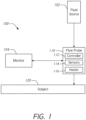
- FIG. 1 illustrates an example embodiment of a subject monitoring system 100 that includes a flow probe 110 that senses a liquid flow rate (e.g., volume flow or mass flow) delivered to a subject or patient 120. Based at least in part on the sensed flow rate, the flow probe 110 provides flow-related data that the system 100 can use to derive a volume of fluid being delivered.
- the fluid can be delivered from a fluid source 102 that can include an IV bag, another in-line port, or a combination of the two.
- the system 100 can include a monitor 104 that can receive the flow-related data from the flow probe 110 and can display this information.
- the monitor 104 can be configured to determine when a fluid bolus is being delivered based on flow rate data received from the flow probe 110 and can differentiate this from fluid maintenance flow rates. In some embodiments, the monitor 104 and/or the flow probe 110 can be configured to display the determined flow rate. A clinician can use this information to gain an understanding of the volume of fluid/mass the subject 120 has received. The system 100 finds particular applicability in determining and tracking the amount of liquid delivered to the subject 120.
- the flow probe 110 (which may also be referred to as a "mass flow sensor” or a “flow rate sensor”) is configured to be in line between the fluid source 102 and the subject 120. This means that the flow of liquid passes through the flow probe 110, that the flow probe 110 is attached to the conduit carrying the fluid, or that the flow probe 110 is positioned (at least partially) within the conduit carrying the liquid.
- Such systems can be differentiated from systems that measure fluid flow or fluid delivery using other means such as by weight of the fluid in the fluid source, the level of fluid in the fluid source, a measure of fluid at the patient end (e.g., fluid suctioned into a collection container), movement of a piston or similar component in a pump, and the like.
- the flow probe 110 can be configured to determine a flow rate using a combination of calorimetric and anemometric techniques (e.g., combining temperature measurements with heater power data).
- the flow probe 110 includes an integrated controller 112, a plurality of temperature sensors 114, and a heater 116.
- the flow probe 110 is configured to apply heat to the liquid flowing through the flow probe by providing power to the heater which in turn heats a thermally-conductive material in contact with the liquid.
- At least one of the temperature sensors 114 measures the temperature of the thermally-conductive material upstream of the heater 116 and at least one other sensor of the temperature sensors 114 measures the temperature of the thermally-conductive material at the heater 116 and/or downstream of the heater 116.
- the controller receives the temperature measurements from the sensors 114 and determines the difference between the upstream temperature and the temperature at the heater 116.
- the controller 112 determines an adjustment to the power to deliver to the heater 116 to achieve a targeted temperature difference based at least in part on the determined temperature difference.
- the controller 112 dynamically updates the power delivered to the heater 116 to achieve the targeted temperature based on updated temperature measurements received from the sensors 114.
- the controller 112 can be part of the monitor 104 or at least a portion of the controller can be part of the monitor 104.
- the monitor 104 can be configured to determine or receive an indication of the power provided to the heater 116 and the temperatures measured by the sensors 114.
- the monitor 104 can be configured to display the received parameters and/or to display additional data determined based on the received parameters.
- the flow probe data can be used to present flow-related data on the monitor 104 or another display via numerical, textual, or pictorial information. This can be displayed or presented in addition to hemodynamic data.
- the information can include a dynamic mass flow rate and/or a mass flow rate history.
- the information can also include one or more recommendations as to fluid administration protocols.
- the monitor 104 provides a user interface to allow a user to adjust characteristics of the flow probe 110.
- the monitor 104 provides a user interface that provides diagnostic data, calibration data, status information, or other information related to the flow probe 110.
- Embodiments of the flow probe 110 can provide dynamic, continuous, intermittent, or on-demand flow rate data in the form of analog or digital signals for use by the monitor 104 or a healthcare provider.
- the flow probe 110 can be cooperatively engaged with a flow controller and controlled by an algorithm.
- the flow probe 110 and a flow controller can be used in an open-loop or closed-loop feedback system to control liquid flow (e.g., from the fluid source 102) based at least in part on measured flow-related data.
- the system 100 includes one or more physiological sensors that provide physiological data to the monitor 104.
- the physiological sensors can include a hemodynamic sensor, for example.
- the hemodynamic sensor can be the FLOTRAC ® sensor, in certain implementations.
- the physiological sensor can be configured to provide information capable of being transformed into one or more forms of heart output data.
- an oximetry device can be used as part of the physiological sensor.
- the oximetry device can be a finger cuff device that is integrated with the system 100, system electronics, and/or the monitor 104.
- the system 100 can utilize the physiological data in an algorithm to determine how the subject 120 responds to administered fluid volumes.
- the algorithm can determine the response of the subject 120, provide information (e.g., a recommendation) to the clinician regarding subsequent bolus administration, and/or control the amount and rate of volume of fluid delivered to the subject 120, e.g., using a flow controller.
- information e.g., a recommendation
- the algorithm can determine the response of the subject 120, provide information (e.g., a recommendation) to the clinician regarding subsequent bolus administration, and/or control the amount and rate of volume of fluid delivered to the subject 120, e.g., using a flow controller.
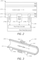
- FIG. 2 illustrates a block diagram of an example flow probe 210 that is configured to determine liquid flow rates based on a hybrid measurement approach.
- the flow probe includes a housing with walls 211 that form a conduit 213 through the flow probe 210 to allow liquid to flow therethrough.
- the flow probe 210 includes thermally-conductive material 215, such as a metal foil or film, attached to the walls 211 along a portion of the walls 211.
- the flow probe 210 includes flow probe electronics 218 that include a flow probe controller 212, temperature sensors 214a, 214b, and a heating element 216.
- the flow probe electronics 218 can also include a power supply, such as a battery, wireless and/or wired communication systems and ports, one or more data stores to store measurement data, calibration data, algorithms, computer-executable instructions, and the like.
- the flow probe 210 is configured to measure fluid flow via thermal mass transport.
- the flow probe 210 includes a shuntless design wherein the entire volume of fluid to be measured flows through the conduit 213, which is a single, continuous passage.
- the flow probe 210 includes a film 215 of thermally-conductive material.
- the flow probe 210 is configured to measure the temperature of the film 215 rather than directly measuring the temperature of the liquid in the conduit 213.
- the controller 212 regulates the heater power to the heating element 216. Based on the heater power delivered and the temperatures measured, the flow rate can be determined by the flow probe controller 212.
- the flow probe 210 is not a semiconductor-based product (e.g., not a complementary metal oxide semiconductor or CMOS). That is, the flow probe electronics 218 are not implemented on a substrate as with typical printed circuit boards.
- the flow probe electronics 218 can be manufactured using discrete electronic components (e.g., thermistors, polyimide, wire heater mats, etc.) and/or MEMS-based fabrication techniques (excluding silicon-based techniques).
- the flow probe electronics 218 use larger-sized components. This is done, in part, to increase the robustness of the flow probe 210 to sterilization techniques that employ radiation that can damage or destroy semi-conductor-based electronics boards.
- the flow probe electronics 218 can include larger-scale electronics to withstand electron beam or gamma-ray sterilization.
- the flow probe electronics 218 can use slightly larger-scale electronic components so that the flow probe 210 survives radioactive sterilization.
- the disclosed flow probes can also include shielding of the electronics to reduce damage caused by e-beam sterilization.
- the flow probe 210 can be configured specifically for tracking liquid flow through an intravenous line.
- the walls 211 of the flow probe 210 can include luer lock connectors on proximal and distal ends to facilitate insertion of the flow probe 210 in an IV line.
- Other connectors can be included on the proximal and/or distal ends of the housing to create a continuous conduit from an insertion line to an out-flow line.
- the flow probe 210 is configured to apply heat to the film 215 (e.g., a metal foil) using the heating element 216.
- the flowing liquid cools the film 215 in a way that is related to the flow rate where the relationship includes non-linear effects.
- the flow probe 210 measures the temperature of the incoming liquid with a proximal or upstream temperature sensor 214a and measures the temperature of the heating element 216 or the film 215 downstream of the heating element using a distal or downstream temperature sensor 214b.
- the controller 212 uses an algorithm based on the measured temperatures to dynamically vary power to the heating element 216 to maintain a constant or targeted temperature difference between the incoming liquid and the film 215.
- the controller 212 is a proportional-integral-derivative controller (or PID).
- PID proportional-integral-derivative controller
- the flow probe 210 can be configured to adjust or to control the electronic system (e.g., the temperature sensors 214a, 214b and heating element 216) to tune PID control parameters.
- the flow probe 210 can be configured to tailor the targeted temperature difference for suitable or desirable results in the range of flow rates and liquid temperatures expected in an IV line.
- the flow probe 210 can be tailored or optimized to operate in a temperature range of at least about 5° C and/or less than or equal to about 50° C, at least about 15° C and/or less than or equal to about 45° C, at least about 20° C and/or less than or equal to about 40° C, or at least about 22° C and/or less than or equal to about 38° C.
- the flow probe 210 can be tailored or optimized to operate in a flow rate range of at least about 0 mL/min (e.g., no flow) and/or less than or equal to about 180 mL/min, at least about 5 mL/min and/or less than or equal to about 170 mL/min, at least about 10 mL/min and/or less than or equal to about 100 mL/min, or at least about 15 mL/min and/or less than or equal to about 70 mL/min.
- the flow probe 210 can be configured to have a sensor response time with a 90% response within at least about 15 seconds, within at least about 10 seconds, within at least about 7 seconds, within at least about 5 seconds, within at least about 2 seconds, or within at least about 1 second.
- the flow probe controller 212 can be configured to relate temperature sensor measurements (e.g., thermistor response signals) to input power provided to the heating element 216.
- the controller 212 can be configured to account for linear and non-linear behavior as well as time lag.
- An advantageous aspect of this design is that there is no need for a full mathematical model of the flow probe.
- the heating element 216 can include wound resistive wire (e.g., Constantan 0.025”), a thin-film heater, or the like.
- induction heating is avoided due at least in part to the high power requirements, making it undesirable in a low-temperature heating application that is the case for measuring liquid flow rates in an IV line.
- the flow probe electronics 218 include a precision power regulator.
- a 14-bit digital-to-analog converter DAC
- Other DACs e.g., 12-bit DAC, 16-bit DAC
- the power regulator can be on-board the probe with continuously controllable and precision power regulation to the heating element 216. In some embodiments, the power regulator can have a relatively fast response time.
- the response time can be less than about 500 ⁇ s, less than about 1 ms, less than about 10 ms, less than about 25 ms, less than about 50 ms, or less than about 100 ms.
- the power regulator can include a DAC in conjunction with pulse-width-modulation (PWM) to emulate a power regulator with a relatively fast response time (e.g., less than about 500 ⁇ s, less than about 1 ms, less than about 10 ms, less than about 25 ms, less than about 50 ms, or less than about 100 ms).
- PWM pulse-width-modulation
- the response time of the power regulator can be configured to ensure that the sensor provides a targeted response time of less than about 15 s, less than about 10 s, less than about 7 s, less than about 5 s, less than about 2 s, or less than about 1 s.
- one or more of the temperature sensors 214a, 214b can be integrated into the heating element 216.
- a heating element temperature sensor combination can be provided using micro-electro-mechanical system (MEMS) technology.
- MEMS micro-electro-mechanical system
- the temperature sensors 214a, 214b can be thermistors.
- the flow probe controller 212 can be configured to account for calibration temperature when characterizing the flow probe system 210.
- the temperature sensors 214a, 214b can be configured to be in contact with the film 215 rather than the liquid in the conduit 213.
- the heating element 216 is configured to directly heat the film 215 rather than the liquid in the conduit 213.
- the temperature sensors 214a, 214b and/or the heating element 216 is secured to the film 215 or foil using thermally-conductive bonding material to ensure contact with the film 215 and accurate temperature measurements.
- the temperature sensors 214a, 214b can be thermistors encapsulated in a glass bead that are bonded to the metal foil or film 215 using, for example, a thermal paste and/or an adhesive resin.
- Flexible circuitry thermistors, thermocouples, thin-film thermocouples, or resistance temperature detectors (RTDs) may also be used for one or more of the temperature sensors 214a, 214b.
- the heating element 216 includes bi-wound lead wires to reduce or eliminate self-generated electromagnetic interference.
- the heating element 216 may also be a wrapped metal core with electrically-insulating, thermally-conductive pads.
- the heating element 216 is a thin metal element or thin film heater that is thermally coupled to the film or metal foil 215.
- the flow probe 210 can be configured to measure the temperature of the heating element 216 away from the heating zone (e.g., using the downstream temperature sensor 214b or a dedicated temperature sensor with the heating element 216).
- the heating element 216 and the temperature sensors 214a, 214b are not in physical contact with the liquid, this advantageously improves sensitivity, reduces energy input, reduces the amount of heating of the IV fluid, improves biocompatibility, and eliminates the need to waterproof thermistors.
- the positioning of the thermistors can be tuned so that the upstream temperature sensor 214a measures temperature in a laminar flow region of the conduit 213.
- the downstream temperature sensor 214b can be positioned distally of the heating element so that it is away from the heating zone but near the heating element 216 to accurately measure its temperature.
- the flow probe 210 can include a characterization of the transfer of heat to the liquid as a function of power input to the heating element 216.
- the flow probe 210 can be configured to maintain a targeted or constant temperature differential between the heated and unheated probes, or the downstream temperature sensor 214b and the upstream temperature sensor 214a, by continuously, intermittently, or periodically varying heater power. The flow rate can be inferred from the power provided to the heating element 216 to maintain this targeted temperature difference.
- FIG. 3 illustrates an example embodiment of a flow probe 310 that is similar to the flow probe 210 described herein with reference to FIG. 2 .
- the flow probe 310 includes a housing that has walls 311 that form a conduit 313 therethrough for a liquid to flow.
- the flow probe 310 includes a metal foil 315 secured to the walls 311 for at least a portion of the path through the conduit 313.
- the flow probe 310 includes a heating element 316 that is configured to provide heat to the metal foil 315.
- the flow probe 310 also includes a proximal thermistor 314a and a distal thermistor 314b on either side of the heating element 316 and in contact with the metal foil 315 outside of the conduit 313.
- the proximal thermistor 314a is configured to measure a temperature of the metal foil 315 upstream of the heating element 316. This temperature measurement is indicative of the temperature of the liquid in the conduit 313.
- the distal thermistor 314b is configured to measure a temperature of the metal foil 315 downstream of the heating element 316. This temperature measurement is indicative of the temperature of the heating element 316 and/or the metal foil 315 downstream of the heating element 316.
- the flow probe 310 includes other electronics, similar to the flow probe electronics 218 of FIG. 2 , that are integrated with the flow probe 310 and can be housed within the housing of the flow probe 310.
- the flow probe 310 is designed so that there is laminar flow at the proximal thermistor 314a.
- the proximal thermistor 314a can be placed at least 25 mm and/or less than or equal to about 50 mm from a proximal end of the conduit 313.
- the proximal thermistor 314a can be placed less than or equal to about 30 mm from a proximal end of the conduit 313, less than or equal to about 35 mm from a proximal end of the conduit 313, less than or equal to about 40 mm from a proximal end of the conduit 313, less than or equal to about 45 mm from a proximal end of the conduit 313, less than or equal to about 50 mm from a proximal end of the conduit 313, or less than or equal to about 55 mm from a proximal end of the conduit 313.
- the distal thermistor 314b is positioned downstream of the heating element 316 a tailored distance to capture an accurate measurement of the temperature of the heated liquid before it has cooled too much. This may be useful because flow rate differences are more distinguishable the closer to the heating element 316 the temperature measurement is acquired. The farther from the heating element 316 the temperature measurement is acquired, the smaller the differences in temperatures are for differing flow rates.
- the distal thermistor 314b can be placed at least 2 mm from the distal end of the heating element 316 and/or less than or equal to about 5 mm from the distal end of the heating element 316, at least 1 mm from the distal end of the heating element 316 and/or less than or equal to about 8 mm from the distal end of the heating element 316, or less than or equal to about 10 mm from the distal end of the heating element 316.
- the precise placement may be tailored or optimized to provide a beneficial balance between stability and sensitivity.
- the distance from the end of the heating element 316 to the distal thermistor 314b can be as small as operably feasible to reduce or minimize heater power requirements due at least in part to the temperature fall off with distance from the heating element 316.
- the heating element 316 can extend laterally to increase the distance along which the metal foil 315, and therefore the liquid in the conduit 313, is heated. A longer or larger heating element 316 facilitates quicker heat transfer to the metal foil 315 and the liquid. Larger or longer heaters also may cause heat to be transferred further away from the boundary at the wall 311 resulting in liquid further from the wall being heated.
- FIG. 4 illustrates a block diagram of another example flow probe 410 that integrates a downstream temperature sensor 414b with the heating element 416.
- the flow probe 410 is similar to the flow probe 210 described herein with reference to FIG. 2 .
- the flow probe 410 may be able to provide a more accurate measurement of the film 415 at the heating element 416, which may improve the accuracy and stability of flow rate calculations.
- this design enables other temperature sensor technologies to be used such as thin-film thermocouples that can be used with thin-film heating elements.
- Elements that are common between the flow probes 210 and 410 retain their respective callouts and a description of these common components will not be repeated here for the sake of clarity and conciseness.
- FIG. 5 illustrates another example flow probe 510, where the flow probe 510 is an embodiment of the flow probe 410 described herein with reference to FIG. 4 .
- the flow probe 510 is also similar to the flow probe 310 described herein with reference to FIG. 3 with a difference being that the distal thermistor 514b is integrated with, or bonded to, the heating element 516.
- this design enables other temperature sensor technologies to be used such as thin-film thermocouples that can be used with thin-film heating elements.
- Elements that are common between the flow probes 310 and 510 retain their respective callouts and a description of these common components will not be repeated here for the sake of clarity and conciseness.
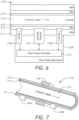
- FIG. 6 illustrates a block diagram of another example flow probe 610 that includes an inner layer 617 between the thermally-conducting film 215 and the conduit 213.
- the flow probe 610 is similar to the flow probe 210 described herein with reference to FIG. 2 .
- the inner layer 617 can be a coating, a portion of the wall 211, or other similar material or feature that prevents physical contact between a liquid flowing through the conduit 213 and the film 215 but that still allows thermal contact between the liquid and the film 215.
- Elements that are common between the flow probes 210 and 610 retain their respective callouts and a description of these common components will not be repeated here for the sake of clarity and conciseness.
- FIG. 7 illustrates another example flow probe 710, where the flow probe 710 is an embodiment of the flow probe 610 described herein with reference to FIG. 6 .
- the flow probe 710 is also similar to the flow probe 310 described herein with reference to FIG. 3 with a difference being the inclusion of an inner layer 717 that prevents or inhibits physical contact while allowing thermal contact between a liquid flowing through the conduit 313 and the film 315.
- the wall 311 can be formed with a cavity that allows the thermally-conducting material 315 to be deposited therein so that a portion of the 311 wall forms the inner layer 717 that is between the liquid and the thermally-conducting material 315.
- a conformal coating of waterproof, biocompatible material can be the inner layer 717.
- FIG. 8 illustrates an example of a flow probe system 830 that is configured to determine flow rates of a liquid flowing through a conduit of an associated flow probe.
- the associated flow probe can be any of the flow probes described herein with reference to FIGS. 1-7 .
- the flow probe system 830 can be integrated as a part of any of those flow probes, such as part of the flow probe electronics 218 described herein with reference to FIG. 2 .
- the flow probe system 830 can employ any method described herein for determining a liquid flow rate, such as the example method 900 described herein with reference to FIG. 9 .
- the flow probe system 830 receives measurement data from temperature sensors 814.
- the temperature sensors 814 can be any of the temperature sensors of the flow probes described herein with reference to FIGS. 1-7 .
- the sensors 814 can include a proximal and a distal temperature sensor (e.g., thermistors) configured to provide upstream and downstream temperature measurements of a thermally-conducting material in thermal contact with the liquid flowing through the flow probe, as described in greater detail herein.
- the flow probe system 830 controls an amount of electrical power provided to a heater 816.
- the heater 816 can be any of the heaters or heating elements described herein.
- the heater 816 can be a thin-film heater coupled to a thermally-conducting material in thermal contact with the liquid flowing through the flow probe, as described in greater detail herein.
- the flow probe system 830 provides electrical power to the heater 816, the heater generates heat that is transferred to the liquid through the thermally-conducting material, thereby raising the temperature of the liquid (or a small band of the liquid in close proximity to the heater 816). This temperature difference is detected and determined by the flow probe system 830 based on the signals indicative of measured temperatures received from the sensors 814.
- the flow probe system 830 can include hardware, software, and/or firmware components for communicating with the sensors 814, controlling the heater 816, and determining a liquid flow rate through an associated flow probe.
- the flow probe system 830 can include one or more processors 832, a data store 833, a temperature module 834, a flow rate module 835, a heater power module 836, and a power regulator 837.
- Components of the flow probe system 830 can communicate with one another, with external systems, and with other components of a subject monitoring system or a network using communication bus 838.
- the flow probe system 830 includes the temperature module 834.
- the temperature module 834 is configured to receive signals from the sensors 814, the signals being indicative of measured temperatures.
- the temperature module 834 converts these signals to temperatures and/or to numbers or signals suitable for further processing in the flow probe system 830 to calculate flow rate and/or to use in determining an output power for the heater 816.
- the temperature module 834 can be configured to determine an upstream or proximal temperature of the thermally-conductive material upstream of the heater 816.
- the temperature module 834 can also be configured to determine a downstream or distal temperature of the thermally-conductive material at the heater 816 or downstream of the heater 816.
- the temperature module 834 can also be configured to determine the temperature difference between the proximal and distal sensors 814.
- the determined temperatures and/or temperature differences can be sent to the flow rate module 835 for determining the flow rate and/or to the heater power module 836 for determining the power to be provided to the heater 816, as described in greater detail herein.
- the flow probe system 830 includes the heater power module 836.
- the heater power module 836 is configured to determine a power to deliver to the heater 816 to maintain a targeted temperature differential as calculated by the temperature module 834. In response to determining that the temperature differential is too large (e.g., greater than a targeted temperature differential), the heater power module 836 can reduce the amount of power for delivery to the heater 816. Similarly, in response to determining that the temperature differential is too small (e.g., less than a targeted temperature differential), the heater power module 836 can increase the amount of power for delivery to the heater 816.
- the heater power module 836 is configured to continuously, intermittently, or periodically determine an updated heater power for delivery to the heater 816 based on updated measurements or calculations received from the temperature module 834.
- the heater power module 836 can dynamically adjust the heater power based on a control scheme, such as a PID control scheme.
- Control parameters e.g., PID parameters
- PID parameters can be stored in the data store 833 for use by the heater power module 836.
- the heater power module 836 can update control parameters based on feedback from the temperature module 834, the flow rate module 835, the power regulator 837, and/or user input.
- the heater power module 836 can communicate the output power to the power regulator 837 and to the flow rate module 835.
- the flow probe system 830 includes the power regulator 837.
- the power regulator 837 receives a power setting from the heater power module 836, regulates a power received from a power supply, and delivers the regulated power to the heater 816.
- the power supply can be internal to the flow probe system 830, such as a battery, or it can be external to the flow probe system 830 where an electrical cable enables transfer of power, such as from a wall outlet, a patient monitor, or other external system or device.
- the power regulator 837 can be a precision power regulator to provide targeted incremental and decremental changes to the heater power to achieve a targeted temperature profile, as described herein.
- the power regulator 837 can control a 14-bit DAC that can be used to provide sub-millivolt resolution over a range of about 15 V.
- the power regulator can have a relatively high temporal resolution or it can include a DAC in conjunction with pulse-width-modulation (PWM) to emulate a relatively high temporal resolution where the temporal resolution of the power regulator is configured to provide a targeted response time of less than about 15 s, less than about 10 s, less than about 7 s, less than about 5 s, less than about 2 s, or less than about 1 s.
- PWM pulse-width-modulation
- the flow probe system 830 includes the flow rate module 835.
- the flow rate module 835 is configured to receive the temperature calculations from the temperature module 834 and the heater power from the heater power module 836 and to determine a liquid flow rate based on these values.
- the flow rate module 835 is configured to determine flow rate by associating the power supplied to the heater 816 to a flow rate based on a targeted temperature differential.
- the flow rate module 835 is configured to compare the measured temperature differential to the targeted temperature differential. In response to determining that the measured differential is outside of an acceptable threshold range of the targeted differential, the flow rate module 835 can eschew calculation of the liquid flow rate and send an indication to the heater power module 836 to adjust the heater power based on the comparison of the measured and target temperature differentials.
- the flow rate module 835 is configured to determine a liquid flow rate based at least in part on a measured temperature differential and a supplied heater power, regardless if it is within a threshold range of a targeted temperature differential. This measurement can be reported with an associated warning or information indicating it is based on a temperature differential that is outside the targeted range.
- the flow rate module 835 accesses a lookup table in the data store 833 that associates temperature differentials and heater power to liquid flow rates.
- the lookup table can be generated at a time when the associated flow probe was calibrated and characterized to accurately associate temperature differential and targeted temperature differentials with liquid flow rates.
- the lookup table can be generated on-site (e.g., at a hospital, in an operating room, or the like) or at the time of manufacture.
- the data store 833 can include a library of calibrations associated with different liquids and/or operating conditions.
- the lookup table can be calibrated for different liquid types (e.g., saline, colloid, crystalloid). This enables a single flow probe to accurately measure flow rates for a variety of IV fluids, for example.
- the flow probe system 830 is in communication with a patient monitor, such as the patient monitor 104 described herein with reference to FIG. 1 .
- user input can be received through the flow probe system 830 (e.g., via the patient monitor or through a user interface associated with the flow probe system 830).
- the user input can be used to inform the flow probe system 830 the type of liquid being used to ensure an appropriate lookup table is used.
- the user input can also be used to respond to prompts from the flow probe system 830 and/or to control operating parameters of the flow probe system 830.
- an algorithm can be implemented to detect a major discontinuity in the baseline flow rate (e.g., a slow, steady flow) and prompt a clinician to confirm that fluid type has not changed.
- the prompt can be provided over the patient monitor, for example.
- the algorithm can be configured to detect a break in the flow of liquids (e.g., no flow) for a period of time, which may indicate that an IV bag is being changed.
- the flow probe system 830 can request confirmation that the fluid type has not been changed.
- the prompt can be provided over the patient monitor, for example.
- a lack of response or if no response is received within a designated time window the flow probe system 830 can resume operation assuming no change in liquid type has occurred.
- the algorithm can be used to determine the fluid type. For example, after a no-flow condition has been determined, the algorithm can be used to calculate thermal dissipation properties after flow begins again and can determine the type of liquid based on these calculated properties. This determination can then be used to select an appropriate calibration lookup table.
- the algorithm can be implemented onboard the flow probe system 830, it can be implemented on the patient monitor, or it can be implemented on a combination of the flow probe system 830 and the patient monitor.
- the flow probe system 830 includes one or more processors 832 that are configured to control operation of the modules 834, 835, 836, the power regulator 837, and the data store 833.
- the one or more processors 832 implement and utilize the software modules, hardware components, and/or firmware elements configured to determine liquid flow rates in an associated flow probe.
- the one or more processors 832 can include any suitable computer processors, application-specific integrated circuits (ASICs), field programmable gate array (FPGAs), or other suitable microprocessors.
- ASICs application-specific integrated circuits
- FPGAs field programmable gate array
- the one or more processors 832 can include other computing components configured to interface with the various modules and data stores of the flow probe system 830.
- the flow probe system 830 includes the data store 833 configured to store configuration data, calibration data, device data, measurement data, lookup tables (e.g., heater power to flow rate, temperature difference to flow rate, heater power and temperature difference to flow rate, etc.) databases, data tables, algorithms, executable instructions (e.g., instructions for the one or more processors 832), and the like.
- the data store 833 can be any suitable data storage device or combination of devices that include, for example and without limitation, random access memory, read-only memory, solid-state disks, hard drives, flash drives, bubble memory, and the like.
- the hardware components of the flow probe system 830 can be discrete components or large-scale electronics. The components can be selected so that flow probe system 830 survives electron-beam (or e-beam) sterilization (e.g., remains operable after the sterilization process).
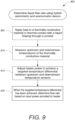
- FIG. 9 illustrates a flow chart of an example method 900 for determining liquid flow rates using a hybrid calorimetric and anemometric device.
- the method 900 can be performed by any of the flow probes described herein with reference to FIGS. 1-7 and/or the flow probe system described herein with reference to FIG. 8 .
- the method 900 will be described as being performed by a flow probe. However, this should not be understood to limit the scope of the disclosure. Rather, any step or portion of the method 900 can be performed by any component or combination of components of the systems described herein.
- the flow probe applies heat to a thermally-conductive material in thermal contact with a liquid flowing through a conduit.
- the flow probe provides power to a heater that is in thermal contact with the thermally-conductive material.
- the heat generated by the heater is transferred to the liquid through the thermally-conductive material.
- the flow probe measures an upstream and a downstream temperature of the thermally-conductive material.
- the upstream temperature measurement is indicative of the temperature of the liquid upstream of the heater or upstream of where heat is being applied to the thermally-conductive material.
- the downstream temperature measurement is indicative of the temperature of the liquid downstream of the heater or downstream of where heat is being applied to the thermally-conductive material.
- the upstream and downstream temperatures can be measured by any suitable temperature sensor, as described herein.
- the flow probe adjusts power to the heater to achieve a targeted temperature differential between the upstream and downstream temperature sensors.
- the targeted temperature differential can be determined prior to operating the flow probe.
- the targeted temperature differential is adjustable, in particular by a user or by the flow probe itself based on temperature measurements and/or heater power calculations.
- the flow probe determines a flow rate of the liquid based at least in part on the measured temperature differential and the power provided to the heater. Where the targeted temperature differential is achieved, the flow probe can determine the flow rate based on the power provided to the heater.
- subject and patient are used interchangeably herein and relate to mammals, inclusive of warm-blooded animals (domesticated and non-domesticated animals), and humans.
- patient and “patient” are used interchangeably herein.
- the term "sensor” as used herein relates to a device, component, or region of a device capable of detecting and/or quantifying and/or qualifying a physiological parameter of a subject.
- the phrase "system” as used herein relates to a device, or combination of devices operating at least in part in a cooperative manner, that is inclusive of the "sensor.”
- Sensors generally include those that continually measure the physiological parameter without user initiation and/or interaction (“continuous sensing device” or “continuous sensor”).
- Continuous sensors include devices and monitoring processes wherein data gaps can and/or do exist, for example, when a continuous pressure sensor is temporarily not providing data, monitoring, or detecting.
- Sensors also generally include those that intermittently measure the physiological parameter with or without user initiation and/or interaction (“intermittent sensing device” or “intermittent sensor”).
- sensors, continuous sensing devices, and/or intermittent sensing devices relate to devices, components, or regions of devices capable of detecting and/or quantifying and/or qualifying a physiological hemodynamic parameter of a subject.
- physiological data include without limitation, parameters directly or indirectly related to providing or calculating blood pressure (BP), stroke volume (SV), cardiac output (CO), end-diastolic volume, ejection fraction, stroke volume variation (SVV), pulse pressure variation (PPV), systolic pressure variations (SPV), extravascular lung water index (ELWI), pulmonary vascular permeability index (PVPI), global end-diastolic index (GEDI), global ejection fraction (GEF), systolic volume index (SVI), arterial blood pressure (ABP), cardiac index (CI), systemic vascular resistance index (SVRI), peripheral resistance (PR), central venous saturation (ScvO2), and plethysmographic variability index (PVI).
- Hemodynamic parameters are inclusive of the absolute value of such parameters, a percentage change or variation in the parameters since an event was recorded, and an absolute percentage change within a previous time segment.
- Electrodes are in electrical connection with (e.g., electrically connected to) the electronic circuitry of a device.
- electronics relate to electronics operatively coupled to the sensor and configured to measure, process, receive, and/or transmit data associated with a sensor, and/or electronics configured to communicate with a monitor or a data acquisition device.
- operatively connected relate to one or more components linked to one or more other components, such that a function is enabled.
- the terms can refer to a mechanical connection, an electrical connection, or any connection that allows transmission of signals between the components.
- one or more transducers can be used to detect pressure and to convert that information into a signal; the signal can then be transmitted to a circuit.
- the transducer is “operably linked” to the electronic circuitry.
- operatively connected,” “operatively linked,” “operably connected,” and “operably linked” include wired and wireless connections.
- controller relates to components and the like designed to perform arithmetic or logic operations using logic circuitry that responds to and processes basic instructions, for example, instructions that drive a computer and/or perform calculations of numbers or their representation (e.g., binary numbers).
- substantially and “substantially” as used herein relate to a sufficient amount that provides a desired function. For example, an amount greater than 50 percent, an amount greater than 60 percent, an amount greater than 70 percent, an amount greater than 80 percent, or an amount greater than 90 percent.
- the term "or” is used in its inclusive sense (and not in its exclusive sense) so that when used, for example, to connect a list of elements, the term “or” means one, some, or all of the elements in the list.
- Conjunctive language such as the phrase "at least one of X, Y and Z," unless specifically stated otherwise, is understood with the context as used in general to convey that an item, term, element, etc. may be either X, Y or Z. Thus, such conjunctive language is not generally intended to imply that certain embodiments require at least one of X, at least one of Y and at least one of Z to each be present.
- Computer software can comprise computer executable code stored in a computer readable medium (e.g., non-transitory computer readable medium) that, when executed, performs the functions described herein.
- computer-executable code is executed by one or more general purpose computer processors.
- any feature or function that can be implemented using software to be executed on a general-purpose computer can also be implemented using a different combination of hardware, software, or firmware.
- such a module can be implemented completely in hardware using a combination of integrated circuits.
- such a feature or function can be implemented completely or partially using specialized computers designed to perform the particular functions described herein rather than by general purpose computers.
- distributed computing devices can be substituted for any one computing device described herein.
- the functions of the one computing device are distributed (e.g., over a network) such that some functions are performed on each of the distributed computing devices.
- equations, algorithms, and/or flowchart illustrations may be implemented using computer program instructions executable on one or more computers. These methods may also be implemented as computer program products either separately, or as a component of an apparatus or system.
- each equation, algorithm, block, or step of a flowchart, and combinations thereof may be implemented by hardware, firmware, and/or software including one or more computer program instructions embodied in computer-readable program code logic.
- any such computer program instructions may be loaded onto one or more computers, including without limitation a general purpose computer or special purpose computer, or other programmable processing apparatus to produce a machine, such that the computer program instructions which execute on the computer(s) or other programmable processing device(s) implement the functions specified in the equations, algorithms, and/or flowcharts. It will also be understood that each equation, algorithm, and/or block in flowchart illustrations, and combinations thereof, may be implemented by special purpose hardware-based computer systems which perform the specified functions or steps, or combinations of special purpose hardware and computer-readable program code logic means.
- computer program instructions such as embodied in computer-readable program code logic, may also be stored in a computer readable memory (e.g., a non-transitory computer readable medium) that can direct one or more computers or other programmable processing devices to function in a particular manner, such that the instructions stored in the computer-readable memory implement the function(s) specified in the block(s) of the flowchart(s).
- a computer readable memory e.g., a non-transitory computer readable medium
- the computer program instructions may also be loaded onto one or more computers or other programmable computing devices to cause a series of operational steps to be performed on the one or more computers or other programmable computing devices to produce a computer-implemented process such that the instructions which execute on the computer or other programmable processing apparatus provide steps for implementing the functions specified in the equation(s), algorithm(s), and/or block(s) of the flowchart(s).
- the computer system may, in some cases, include multiple distinct computers or computing devices (e.g., physical servers, workstations, storage arrays, etc.) that communicate and interoperate over a network to perform the described functions.
- Each such computing device typically includes a processor (or multiple processors) that executes program instructions or modules stored in a memory or other non-transitory computer-readable storage medium or device.
- the various functions disclosed herein may be embodied in such program instructions, although some or all of the disclosed functions may alternatively be implemented in application-specific circuitry (e.g., ASICs or FPGAs) of the computer system. Where the computer system includes multiple computing devices, these devices may, but need not, be co-located.
- the results of the disclosed methods and tasks may be persistently stored by transforming physical storage devices, such as solid-state memory chips and/or magnetic disks, into a different state.
Landscapes
- Physics & Mathematics (AREA)
- Fluid Mechanics (AREA)
- General Physics & Mathematics (AREA)
- Health & Medical Sciences (AREA)
- Vascular Medicine (AREA)
- Engineering & Computer Science (AREA)
- Anesthesiology (AREA)
- Biomedical Technology (AREA)
- Heart & Thoracic Surgery (AREA)
- Hematology (AREA)
- Life Sciences & Earth Sciences (AREA)
- Animal Behavior & Ethology (AREA)
- General Health & Medical Sciences (AREA)
- Public Health (AREA)
- Veterinary Medicine (AREA)
- Measuring Volume Flow (AREA)
- Measuring Pulse, Heart Rate, Blood Pressure Or Blood Flow (AREA)
Claims (15)
- Durchflusssonde (210, 310, 410, 510, 610, 710), umfassend:ein Gehäuse mit Wänden (211), die eine Rohrleitung (213) bilden, damit eine Flüssigkeit dort hindurch fließen kann;ein wärmeleitfähiges Material (215), das an einem Abschnitt der Wände (211) befestigt ist, so dass das wärmeleitfähige Material in thermischem Kontakt mit einer durch die Rohrleitung (213) fließenden Flüssigkeit ist;ein Heizelement (216) in thermischem Kontakt mit dem wärmeleitfähigen Material (215), so dass das Heizelement der Rohrleitung (213) nicht ausgesetzt ist;einen proximalen Temperatursensor (214a) stromaufwärts von dem Heizelement (216), wobei der proximale Temperatursensor in thermischem Kontakt mit dem wärmeleitfähigen Material (215) ist, so dass der proximale Temperatursensor der Rohrleitung (213) nicht ausgesetzt ist;einen distalen Temperatursensor (214b) stromabwärts von dem Heizelement (216), wobei der distale Temperatursensor in thermischem Kontakt mit dem wärmeleitfähigen Material ist, so dass der distale Temperatursensor der Rohrleitung (213) nicht ausgesetzt ist; undeine Steuerung (212) in Kommunikation mit dem Heizelement (216), dem proximalen Temperatursensor (214a) und dem distalen Temperatursensor (214b), wobei die Steuerung (212) ausgestaltet ist zum:Steuern des Heizelements (216), um Wärme auf das wärmeleitfähige Material (215) anzuwenden;Bestimmen einer stromaufwärtigen Temperatur basierend mindestens teilweise auf Signalen, die von dem proximalen Temperatursensor (214a) empfangen wurden;Bestimmen einer stromabwärtigen Temperatur basierend mindestens teilweise auf Signalen, die von dem distalen Temperatursensor (214b) empfangen wurden;Anpassen einer Heizerleistung, die dem Heizelement (216) bereitgestellt wird, basierend mindestens teilweise auf einer bestimmten Temperaturdifferenz zwischen der stromabwärtigen Temperatur und der stromaufwärtigen Temperatur, wobei die Anpassung an die Heizerleistung so ausgestaltet ist, dass eine anpassbare Zieltemperaturdifferenz erreicht wird;
undwenn die Zieltemperaturdifferenz erreicht worden ist, Bestimmen einer Flüssigkeitsdurchflussrate unter Verwendung der angepassten Heizerleistung, die dem Heizelement bereitgestellt wird, und der erreichten Temperaturdifferenz zwischen der stromabwärtigen Temperatur und der stromaufwärtigen Temperatur. - Durchflusssonde nach Anspruch 1, des Weiteren umfassend Systemelektronik (218) in Kommunikation mit dem proximalen und dem distalen Temperatursensor (214a, 214b), der Steuerung (212) und dem Heizelement (216), wobei die Systemelektronik (218) Elektronik im Großmaßstab einschließt, die ausgestaltet ist, um Elektronenstrahl- oder Gammastrahlensterilisation zu widerstehen.
- Durchflusssonde nach einem der Ansprüche 1 oder 2, wobei die Systemelektronik (218) nicht auf Halbleiterbasis ist und diskrete elektronische Komponenten oder Komponenten auf MEMS-Basis einschließt.
- Durchflusssonde (610) nach einem der Ansprüche 1 bis 3, wobei das Gehäuse des Weiteren eine konforme Beschichtung (617) aus wasserfestem biokompatiblem Material auf einer Innenseite des wärmeleitfähigen Films einschließt.
- Durchflusssonde (410) nach einem der Ansprüche 1 bis 4, wobei die Durchflusssonde ausgestaltet ist, um in einer intravenösen Leitung verwendet zu werden, und wobei der proximale Temperatursensor (214a) zwischen 25 mm und 50 mm von einem proximalen Ende der Rohrleitung positioniert ist, und der distale Temperatursensor (214b) weniger als oder gleich 5 mm von einem distalen Ende des Heizelements (216) positioniert ist, oder wobei der distale Temperatursensor (414b) in das Heizelement (416) integriert ist.
- Durchflusssonde nach einem der Ansprüche 1 bis 5, wobei das Heizelement (216) ein Dünnfilm-Heizelement ist.
- Durchflusssonde nach einem der Ansprüche 1 bis 6, wobei die Steuerung (212) ein Proportional-Integral-Differential-Steuerschema zum Steuern des Heizelements implementiert.
- Durchflusssonde nach einem der Ansprüche 1 bis 7, wobei die Durchflusssonde zur Verwendung mit Flüssigkeiten in einem Temperaturbereich größer als oder gleich 5 °C und kleiner als oder gleich 50 °C ausgestaltet ist.
- Durchflusssonde nach einem der Ansprüche 1 bis 8, wobei die Durchflusssonde zur Verwendung mit Flüssigkeiten mit Durchflussraten in einem Bereich größer als oder gleich 0 Millilitern pro Minute und kleiner als 180 Millilitern pro Minute ausgestaltet ist.
- Durchflusssonde nach einem der Ansprüche 1 bis 9, wobei die Steuerung (212) ausgestaltet ist, um die Flüssigkeitsdurchflussrate unter Verwendung einer Nachschlagtabelle zu bestimmen, die basierend auf einer Zieltemperaturdifferenz die Temperaturdifferenzen zwischen der stromabwärtigen Temperatur und der stromaufwärtigen Temperatur und die bereitgestellte Heizerleistung den Flüssigkeitsdurchflussraten zuordnet.
- Durchflusssonde nach Anspruch 10, wobei die Durchflusssonde ausgestaltet ist, um Anpassung der Zieltemperaturdifferenz zwischen der stromaufwärtigen Temperatur und der stromabwärtigen Temperatur durch einen Benutzer zuzulassen, oder die Zieltemperaturdifferenz zwischen der stromaufwärtigen Temperatur und der stromabwärtigen Temperatur basierend auf Temperaturmessungen oder Heizerleistungsberechnungen anzupassen.
- Verfahren (900) zum Bestimmen der Flüssigkeitsdurchflussrate unter Verwendung einer Durchflusssondenvorrichtung (210), wobei das Verfahren umfasst:Anwenden (905) von Wärme auf ein wärmeleitfähiges Material (215) in thermischem Kontakt mit einer Flüssigkeit, die durch eine Rohrleitung (213) der Durchflusssondenvorrichtung fließt;Messen (910) einer stromaufwärtigen Temperatur stromaufwärts von einem Heizelement (216) der Durchflusssondenvorrichtung;Messen (910) einer stromabwärtigen Temperatur stromabwärts von dem Heizelement (216);Anpassen (915) der Heizerleistung, die dem Heizelement bereitgestellt wird, um eine anpassbare Zieltemperaturdifferenz zwischen der stromaufwärtigen Temperatur und der stromabwärtigen Temperatur zu erreichen; undwenn die Zieltemperaturdifferenz erreicht worden ist, Bestimmen (920) einer Flüssigkeitsdurchflussrate unter Verwendung der angepassten Heizerleistung, die dem Heizelement (216) bereitgestellt wird, und der erreichten Temperaturdifferenz zwischen der stromabwärtigen Temperatur und der stromaufwärtigen Temperatur.
- Verfahren nach Anspruch 12, wobei Messen der stromaufwärtigen Temperatur Messen einer Temperatur des wärmeleitfähigen Materials einschließt, und Messen der stromabwärtigen Temperatur Messen einer Temperatur des wärmeleitfähigen Materials an dem Heizelement (216) einschließt.
- Verfahren nach Anspruch 12 oder 13, wobei Bestimmen der Flüssigkeitsdurchflussrate Verwenden einer Nachschlagtabelle umfasst, die basierend auf einer Zieltemperaturdifferenz die Temperaturdifferenzen zwischen der stromabwärtigen Temperatur und der stromaufwärtigen Temperatur und die bereitgestellte Heizerleistung den Flüssigkeitsdurchflussraten zuordnet.
- Verfahren nach einem der Ansprüche 12 bis 14, des Weiteren umfassend Anpassen der Zieltemperaturdifferenz zwischen der stromaufwärtigen Temperatur und der stromabwärtigen Temperatur.
Applications Claiming Priority (2)
| Application Number | Priority Date | Filing Date | Title |
|---|---|---|---|
| US201862782597P | 2018-12-20 | 2018-12-20 | |
| PCT/US2019/065917 WO2020131557A1 (en) | 2018-12-20 | 2019-12-12 | Thermal mass fluid flow sensor |
Publications (3)
| Publication Number | Publication Date |
|---|---|
| EP3899445A1 EP3899445A1 (de) | 2021-10-27 |
| EP3899445B1 true EP3899445B1 (de) | 2024-12-25 |
| EP3899445C0 EP3899445C0 (de) | 2024-12-25 |
Family
ID=69160342
Family Applications (1)
| Application Number | Title | Priority Date | Filing Date |
|---|---|---|---|
| EP19836322.8A Active EP3899445B1 (de) | 2018-12-20 | 2019-12-12 | Thermischer massendurchflusssensor |
Country Status (4)
| Country | Link |
|---|---|
| US (1) | US12399050B2 (de) |
| EP (1) | EP3899445B1 (de) |
| CN (1) | CN113366285A (de) |
| WO (1) | WO2020131557A1 (de) |
Families Citing this family (15)
| Publication number | Priority date | Publication date | Assignee | Title |
|---|---|---|---|---|
| JP7634201B2 (ja) * | 2021-03-12 | 2025-02-21 | パナソニックIpマネジメント株式会社 | 流量計 |
| CN114366859B (zh) * | 2021-10-29 | 2024-09-13 | 首都医科大学宣武医院 | 一种脑脊液引流及脑温自动监测装置 |
| EP4392746B1 (de) | 2021-11-28 | 2025-05-07 | Nvention Ltd | Durchflussmessvorrichtung und -verfahren |
| US20240044684A1 (en) * | 2022-04-22 | 2024-02-08 | Carilion Clinic | Device for measuring rate of body fluid flow through a tube |
| CN115177820A (zh) * | 2022-06-15 | 2022-10-14 | 谢玉花 | 输液加温测速控制系统及控制方法 |
| CN115177819A (zh) * | 2022-06-15 | 2022-10-14 | 中国人民解放军海军军医大学第一附属医院 | 用于输液加温测速的控制系统及控制方法 |
| US12385770B2 (en) * | 2022-12-13 | 2025-08-12 | Halliburton Energy Services, Inc. | System and method of determining reservoir fluid flow condition and composition downhole |
| CN116429194B (zh) * | 2022-12-26 | 2026-02-24 | 上海矽睿科技股份有限公司 | 流量传感器模块及流量计 |
| US20240255332A1 (en) * | 2023-01-30 | 2024-08-01 | Advanced Energy Industries, Inc. | Compact fluid flow sensor |
| KR102894301B1 (ko) * | 2023-05-17 | 2025-12-02 | (주)시큐어포인트 | 온도 마킹 방식의 링거액 유량측정 장치 |
| US20250020496A1 (en) * | 2023-07-11 | 2025-01-16 | Tech4Imaging Llc | Multidimensional capacitance multiphase flow meter |
| WO2025186626A1 (en) * | 2024-03-07 | 2025-09-12 | Abb Schweiz Ag | A flowmeter for a conduit |
| NL2037975B1 (en) * | 2024-06-18 | 2026-01-12 | Sencilia B V | Microflow sensor |
| CN119701134B (zh) * | 2025-02-06 | 2025-10-10 | 中国人民解放军海军军医大学第一附属医院 | 输液袋用输液辅助装置及温压控制模型的构建方法 |
| CN120467460A (zh) * | 2025-07-11 | 2025-08-12 | 安徽皖仪科技股份有限公司 | 一种基于纳升流量传感器的流量检测电路 |
Citations (3)
| Publication number | Priority date | Publication date | Assignee | Title |
|---|---|---|---|---|
| US5339687A (en) * | 1989-02-18 | 1994-08-23 | Endress & Hauser Limited | Flowmeter |
| US20040173019A1 (en) * | 2002-05-28 | 2004-09-09 | Mcmillan Robert M. | High accuracy measuring and control of low fluid flow rates |
| US7387022B1 (en) * | 2007-05-02 | 2008-06-17 | Honeywell International Inc. | Thermal mass flow transducer including PWM-type heater current driver |
Family Cites Families (37)
| Publication number | Priority date | Publication date | Assignee | Title |
|---|---|---|---|---|
| US1156638A (en) * | 1914-01-13 | 1915-10-12 | Gen Electric | Flow-meter. |
| US2583561A (en) * | 1946-10-23 | 1952-01-29 | General Joseph | Electronic air flow indicator |
| US4384578A (en) * | 1981-04-16 | 1983-05-24 | The United States Of America As Represented By The Administrator Of The National Aeronautics And Space Administration | Bio-medical flow sensor |
| US4548078A (en) * | 1982-09-30 | 1985-10-22 | Honeywell Inc. | Integral flow sensor and channel assembly |
| US4651564A (en) * | 1982-09-30 | 1987-03-24 | Honeywell Inc. | Semiconductor device |
| US4713970A (en) * | 1984-08-29 | 1987-12-22 | General Motors Corporation | Thermal diffusion fluid flow sensor |
| US4813280A (en) | 1987-04-01 | 1989-03-21 | The Dow Chemical Company | Thermal pulse flow meter with disposable cell |
| DE4219551C2 (de) | 1991-06-13 | 1996-04-18 | Mks Japan Inc | Massenströmungssensor |
| JP3175887B2 (ja) * | 1992-10-27 | 2001-06-11 | 株式会社半導体エネルギー研究所 | 測定装置 |
| ATE222354T1 (de) | 1997-12-30 | 2002-08-15 | Qualiflow S A | Verfahren zu herstellung von einem sensor für einen thermischen massendurchflussmesser |
| JP2000227354A (ja) | 1998-12-01 | 2000-08-15 | Nippon M K S Kk | 流量センサ |
| US6361206B1 (en) * | 1999-01-28 | 2002-03-26 | Honeywell International Inc. | Microsensor housing |
| NL1014797C2 (nl) * | 2000-03-30 | 2001-10-02 | Berkin Bv | Massadebietmeter. |
| US20030130625A1 (en) * | 2002-01-07 | 2003-07-10 | Jacobson James D. | Infusion system |
| EP1365216B1 (de) * | 2002-05-10 | 2018-01-17 | Azbil Corporation | Durchflusssensor und Verfahren zu dessen Herstellung |
| US6736005B2 (en) * | 2002-05-28 | 2004-05-18 | Mcmillan Company | High accuracy measuring and control of low fluid flow rates |
| US6883370B2 (en) | 2002-06-28 | 2005-04-26 | Heetronix | Mass flow meter with chip-type sensors |
| US7107835B2 (en) * | 2004-09-08 | 2006-09-19 | Honeywell International Inc. | Thermal mass flow sensor |
| US7857506B2 (en) | 2005-12-05 | 2010-12-28 | Sencal Llc | Disposable, pre-calibrated, pre-validated sensors for use in bio-processing applications |
| US9575087B2 (en) | 2012-09-06 | 2017-02-21 | Parker-Hannifin Corporation | Risk-managed, single-use, pre-calibrated, pre-sterilized sensors for use in bio-processing applications |
| JP4962489B2 (ja) | 2006-03-28 | 2012-06-27 | 株式会社島津製作所 | 熱式質量流量計 |
| US20110009720A1 (en) * | 2006-11-02 | 2011-01-13 | Kislaya Kunjan | Continuous whole blood glucose monitor |
| CA2721214A1 (en) | 2008-04-10 | 2009-10-15 | Abbott Diabetes Care Inc. | Method and system for sterilizing an analyte sensor |
| JP2010057898A (ja) | 2008-08-08 | 2010-03-18 | Ricoh Co Ltd | 薬液注入量調整装置及び薬液注入量調整方法、並びに薬液注入システム |
| US8186332B2 (en) | 2009-07-20 | 2012-05-29 | Mann & Hummel Gmbh | Fluid filter with integrated temperature regulation |
| WO2011011814A1 (en) * | 2009-07-30 | 2011-02-03 | Acu Rate Pty Limited | An administration set flow condition monitor |
| US8887477B2 (en) * | 2009-11-16 | 2014-11-18 | Cordis Corporation | E beam sterilization of medical devices comprising bioactive coating |
| IL205084A (en) * | 2010-04-14 | 2017-08-31 | Vasa Applied Tech Ltd | Probe learned flow |
| US9186457B2 (en) | 2011-04-27 | 2015-11-17 | Freddie Eng Hwee Lee | Intravenous infusion monitoring apparatus, system and method |
| US20120291540A1 (en) | 2011-05-20 | 2012-11-22 | Cooke Dominic J | Infusion Apparatus With Flow Detector |
| DE102013108099A1 (de) | 2012-10-19 | 2014-04-24 | Endress + Hauser Flowtec Ag | Thermisches Durchflussmessgerät |
| SG2012080636A (en) | 2012-10-31 | 2014-05-29 | Eng Hwee Freddie Lee | Intravenous (iv) infusion monitoring method and system |
| EP2954293A4 (de) * | 2013-02-08 | 2017-03-15 | Provtagaren AB | Verbesserte differentielle wärmemassendurchflussmessanordnung und verfahren zur messung eines massendurchflusses unter verwendung der besagten massendurchflussmessanordnung |
| CN103369748B (zh) * | 2013-07-25 | 2016-09-07 | 吴让攀 | 一种用于加热液体的电热管 |
| JP6369379B2 (ja) * | 2014-06-03 | 2018-08-08 | 株式会社デンソー | 質量流量計および速度計 |
| WO2017075004A1 (en) | 2015-10-27 | 2017-05-04 | Memsic, Inc. | Removable high flow impedance module in flow sensor bypass circuit |
| DE102016115403A1 (de) * | 2016-08-19 | 2018-02-22 | Hamilton Bonaduz Ag | Autonome Vorrichtung zum Erfassen von Eigenschaften eines Messmediums und Verfahren dafür |
-
2019
- 2019-12-12 WO PCT/US2019/065917 patent/WO2020131557A1/en not_active Ceased
- 2019-12-12 CN CN201980090377.1A patent/CN113366285A/zh active Pending
- 2019-12-12 EP EP19836322.8A patent/EP3899445B1/de active Active
-
2021
- 2021-06-18 US US17/352,240 patent/US12399050B2/en active Active
Patent Citations (3)
| Publication number | Priority date | Publication date | Assignee | Title |
|---|---|---|---|---|
| US5339687A (en) * | 1989-02-18 | 1994-08-23 | Endress & Hauser Limited | Flowmeter |
| US20040173019A1 (en) * | 2002-05-28 | 2004-09-09 | Mcmillan Robert M. | High accuracy measuring and control of low fluid flow rates |
| US7387022B1 (en) * | 2007-05-02 | 2008-06-17 | Honeywell International Inc. | Thermal mass flow transducer including PWM-type heater current driver |
Also Published As
| Publication number | Publication date |
|---|---|
| WO2020131557A1 (en) | 2020-06-25 |
| CN113366285A (zh) | 2021-09-07 |
| US20210310840A1 (en) | 2021-10-07 |
| US12399050B2 (en) | 2025-08-26 |
| EP3899445A1 (de) | 2021-10-27 |
| EP3899445C0 (de) | 2024-12-25 |
Similar Documents
| Publication | Publication Date | Title |
|---|---|---|
| EP3899445B1 (de) | Thermischer massendurchflusssensor | |
| US12491357B2 (en) | Systems and methods for determining a blood volume flow through a cardiac support system and vascular support system | |
| CN110121291B (zh) | 用于确定温度的贴片 | |
| USRE47403E1 (en) | Calibration of sensors or measuring systems | |
| US5509424A (en) | Continuous cardiac output monitoring system | |
| JP3557211B2 (ja) | 連続血流量を低電力で測定する方法および装置 | |
| US5588438A (en) | System and method for controlling the temperature of a catheter-mounted heater | |
| JP5590600B2 (ja) | 金属製導管を電気で加熱することにより流体流を加熱する装置 | |
| JP5558463B2 (ja) | 流れ制御のためのセンサ及び制御ユニット、並びに流体の制御送達のための方法 | |
| RU2562229C2 (ru) | Устройство для мониторинга положения дистального конца трубки относительно кровеносного сосуда | |
| EP0558713A1 (de) | Temperaturregeleinrichtung und kalibrierverfahren | |
| US20220378993A1 (en) | Balancing Method and Balancing Unit Being Independent of Temperature Disturbance | |
| US4627840A (en) | Flow monitoring device | |
| Mimoun et al. | Thermal flow sensors on flexible substrates for minimally invasive medical instruments | |
| US20180200432A1 (en) | Device for administering drug solution | |
| US5954659A (en) | Method and apparatus for invasively measuring cardiac output by detecting temperature differences of blood heated by radiation | |
| CA2129751C (en) | System and method for controlling the temperature of a catheter-mounted heater | |
| US9599521B2 (en) | Interface between vital-signs sensors and patient monitor | |
| JPWO2020025337A5 (de) | ||
| NL2037975B1 (en) | Microflow sensor | |
| WO2019027895A1 (en) | METHOD AND DEVICE FOR CALIBRATING CAPILLARY BLOOD FLOWMETER | |
| US20180243491A1 (en) | Pump for conveying fluids, and method for determining a flow rate | |
| Hjertaker et al. | A thermometry system for quality assurance and documentation of whole body hyperthermia procedures | |
| CN121606774A (zh) | 一种输液方法和系统 | |
| Difallah et al. | Nonlinearity Issues in Respiratory Flow Measurement in Constant Temperature Mode |
Legal Events
| Date | Code | Title | Description |
|---|---|---|---|
| STAA | Information on the status of an ep patent application or granted ep patent |
Free format text: STATUS: UNKNOWN |
|
| STAA | Information on the status of an ep patent application or granted ep patent |
Free format text: STATUS: THE INTERNATIONAL PUBLICATION HAS BEEN MADE |
|
| PUAI | Public reference made under article 153(3) epc to a published international application that has entered the european phase |
Free format text: ORIGINAL CODE: 0009012 |
|
| STAA | Information on the status of an ep patent application or granted ep patent |
Free format text: STATUS: REQUEST FOR EXAMINATION WAS MADE |
|
| 17P | Request for examination filed |
Effective date: 20210720 |
|
| AK | Designated contracting states |
Kind code of ref document: A1 Designated state(s): AL AT BE BG CH CY CZ DE DK EE ES FI FR GB GR HR HU IE IS IT LI LT LU LV MC MK MT NL NO PL PT RO RS SE SI SK SM TR |
|
| RIN1 | Information on inventor provided before grant (corrected) |
Inventor name: CAO, HENGCHU Inventor name: AL HATIB, FERAS Inventor name: HIPSZER, BRIAN, R. Inventor name: TRIPATHY, SAKYASINGH Inventor name: FEAGLER, COLE, EMERSON |
|
| DAV | Request for validation of the european patent (deleted) | ||
| DAX | Request for extension of the european patent (deleted) | ||
| STAA | Information on the status of an ep patent application or granted ep patent |
Free format text: STATUS: EXAMINATION IS IN PROGRESS |
|
| 17Q | First examination report despatched |
Effective date: 20221221 |
|
| P01 | Opt-out of the competence of the unified patent court (upc) registered |
Effective date: 20230905 |
|
| GRAP | Despatch of communication of intention to grant a patent |
Free format text: ORIGINAL CODE: EPIDOSNIGR1 |
|
| STAA | Information on the status of an ep patent application or granted ep patent |
Free format text: STATUS: GRANT OF PATENT IS INTENDED |
|
| RIC1 | Information provided on ipc code assigned before grant |
Ipc: G01F 1/698 20060101ALI20240531BHEP Ipc: G01F 1/696 20060101ALI20240531BHEP Ipc: A61M 5/168 20060101ALI20240531BHEP Ipc: G01F 1/684 20060101AFI20240531BHEP |
|
| INTG | Intention to grant announced |
Effective date: 20240624 |
|
| GRAS | Grant fee paid |
Free format text: ORIGINAL CODE: EPIDOSNIGR3 |
|
| GRAA | (expected) grant |
Free format text: ORIGINAL CODE: 0009210 |
|
| STAA | Information on the status of an ep patent application or granted ep patent |
Free format text: STATUS: THE PATENT HAS BEEN GRANTED |
|
| RAP1 | Party data changed (applicant data changed or rights of an application transferred) |
Owner name: BECTON, DICKINSON AND COMPANY |
|
| AK | Designated contracting states |
Kind code of ref document: B1 Designated state(s): AL AT BE BG CH CY CZ DE DK EE ES FI FR GB GR HR HU IE IS IT LI LT LU LV MC MK MT NL NO PL PT RO RS SE SI SK SM TR |
|
| REG | Reference to a national code |
Ref country code: GB Ref legal event code: FG4D |
|
| REG | Reference to a national code |
Ref country code: CH Ref legal event code: EP |
|
| REG | Reference to a national code |
Ref country code: DE Ref legal event code: R096 Ref document number: 602019064039 Country of ref document: DE |
|
| REG | Reference to a national code |
Ref country code: IE Ref legal event code: FG4D |
|
| U01 | Request for unitary effect filed |
Effective date: 20250122 |
|
| U07 | Unitary effect registered |
Designated state(s): AT BE BG DE DK EE FI FR IT LT LU LV MT NL PT RO SE SI Effective date: 20250128 |
|
| P04 | Withdrawal of opt-out of the competence of the unified patent court (upc) registered |
Free format text: CASE NUMBER: APP_3893/2025 Effective date: 20250124 |
|
| PG25 | Lapsed in a contracting state [announced via postgrant information from national office to epo] |
Ref country code: HR Free format text: LAPSE BECAUSE OF FAILURE TO SUBMIT A TRANSLATION OF THE DESCRIPTION OR TO PAY THE FEE WITHIN THE PRESCRIBED TIME-LIMIT Effective date: 20241225 |
|
| PG25 | Lapsed in a contracting state [announced via postgrant information from national office to epo] |
Ref country code: NO Free format text: LAPSE BECAUSE OF FAILURE TO SUBMIT A TRANSLATION OF THE DESCRIPTION OR TO PAY THE FEE WITHIN THE PRESCRIBED TIME-LIMIT Effective date: 20250325 |
|
| PG25 | Lapsed in a contracting state [announced via postgrant information from national office to epo] |
Ref country code: GR Free format text: LAPSE BECAUSE OF FAILURE TO SUBMIT A TRANSLATION OF THE DESCRIPTION OR TO PAY THE FEE WITHIN THE PRESCRIBED TIME-LIMIT Effective date: 20250326 |
|
| PG25 | Lapsed in a contracting state [announced via postgrant information from national office to epo] |
Ref country code: RS Free format text: LAPSE BECAUSE OF FAILURE TO SUBMIT A TRANSLATION OF THE DESCRIPTION OR TO PAY THE FEE WITHIN THE PRESCRIBED TIME-LIMIT Effective date: 20250325 |
|
| PG25 | Lapsed in a contracting state [announced via postgrant information from national office to epo] |
Ref country code: SM Free format text: LAPSE BECAUSE OF FAILURE TO SUBMIT A TRANSLATION OF THE DESCRIPTION OR TO PAY THE FEE WITHIN THE PRESCRIBED TIME-LIMIT Effective date: 20241225 |
|
| PG25 | Lapsed in a contracting state [announced via postgrant information from national office to epo] |
Ref country code: PL Free format text: LAPSE BECAUSE OF FAILURE TO SUBMIT A TRANSLATION OF THE DESCRIPTION OR TO PAY THE FEE WITHIN THE PRESCRIBED TIME-LIMIT Effective date: 20241225 |
|
| PG25 | Lapsed in a contracting state [announced via postgrant information from national office to epo] |
Ref country code: ES Free format text: LAPSE BECAUSE OF FAILURE TO SUBMIT A TRANSLATION OF THE DESCRIPTION OR TO PAY THE FEE WITHIN THE PRESCRIBED TIME-LIMIT Effective date: 20241225 |
|
| PG25 | Lapsed in a contracting state [announced via postgrant information from national office to epo] |
Ref country code: IS Free format text: LAPSE BECAUSE OF FAILURE TO SUBMIT A TRANSLATION OF THE DESCRIPTION OR TO PAY THE FEE WITHIN THE PRESCRIBED TIME-LIMIT Effective date: 20250425 |
|
| PG25 | Lapsed in a contracting state [announced via postgrant information from national office to epo] |
Ref country code: SK Free format text: LAPSE BECAUSE OF FAILURE TO SUBMIT A TRANSLATION OF THE DESCRIPTION OR TO PAY THE FEE WITHIN THE PRESCRIBED TIME-LIMIT Effective date: 20241225 |
|
| PG25 | Lapsed in a contracting state [announced via postgrant information from national office to epo] |
Ref country code: CZ Free format text: LAPSE BECAUSE OF FAILURE TO SUBMIT A TRANSLATION OF THE DESCRIPTION OR TO PAY THE FEE WITHIN THE PRESCRIBED TIME-LIMIT Effective date: 20241225 |
|
| PLBE | No opposition filed within time limit |
Free format text: ORIGINAL CODE: 0009261 |
|
| STAA | Information on the status of an ep patent application or granted ep patent |
Free format text: STATUS: NO OPPOSITION FILED WITHIN TIME LIMIT |
|
| 26N | No opposition filed |
Effective date: 20250926 |
|
| U20 | Renewal fee for the european patent with unitary effect paid |
Year of fee payment: 7 Effective date: 20251119 |
|
| PGFP | Annual fee paid to national office [announced via postgrant information from national office to epo] |
Ref country code: GB Payment date: 20251119 Year of fee payment: 7 |